EP2864778B1 - Cadre de colonne de chromatographie et procédé d'entretien et de remplissage de colonne de chromatographie - Google Patents
Cadre de colonne de chromatographie et procédé d'entretien et de remplissage de colonne de chromatographie Download PDFInfo
- Publication number
- EP2864778B1 EP2864778B1 EP13807156.8A EP13807156A EP2864778B1 EP 2864778 B1 EP2864778 B1 EP 2864778B1 EP 13807156 A EP13807156 A EP 13807156A EP 2864778 B1 EP2864778 B1 EP 2864778B1
- Authority
- EP
- European Patent Office
- Prior art keywords
- adaptor
- frame
- end unit
- rod
- tubular housing
- Prior art date
- Legal status (The legal status is an assumption and is not a legal conclusion. Google has not performed a legal analysis and makes no representation as to the accuracy of the status listed.)
- Active
Links
Images


Classifications
-
- G—PHYSICS
- G01—MEASURING; TESTING
- G01N—INVESTIGATING OR ANALYSING MATERIALS BY DETERMINING THEIR CHEMICAL OR PHYSICAL PROPERTIES
- G01N30/00—Investigating or analysing materials by separation into components using adsorption, absorption or similar phenomena or using ion-exchange, e.g. chromatography or field flow fractionation
- G01N30/02—Column chromatography
- G01N30/60—Construction of the column
- G01N30/6047—Construction of the column with supporting means; Holders
-
- B—PERFORMING OPERATIONS; TRANSPORTING
- B01—PHYSICAL OR CHEMICAL PROCESSES OR APPARATUS IN GENERAL
- B01D—SEPARATION
- B01D15/00—Separating processes involving the treatment of liquids with solid sorbents; Apparatus therefor
- B01D15/08—Selective adsorption, e.g. chromatography
- B01D15/10—Selective adsorption, e.g. chromatography characterised by constructional or operational features
-
- B—PERFORMING OPERATIONS; TRANSPORTING
- B01—PHYSICAL OR CHEMICAL PROCESSES OR APPARATUS IN GENERAL
- B01D—SEPARATION
- B01D15/00—Separating processes involving the treatment of liquids with solid sorbents; Apparatus therefor
- B01D15/08—Selective adsorption, e.g. chromatography
- B01D15/10—Selective adsorption, e.g. chromatography characterised by constructional or operational features
- B01D15/20—Selective adsorption, e.g. chromatography characterised by constructional or operational features relating to the conditioning of the sorbent material
- B01D15/206—Packing or coating
-
- B—PERFORMING OPERATIONS; TRANSPORTING
- B01—PHYSICAL OR CHEMICAL PROCESSES OR APPARATUS IN GENERAL
- B01D—SEPARATION
- B01D15/00—Separating processes involving the treatment of liquids with solid sorbents; Apparatus therefor
- B01D15/08—Selective adsorption, e.g. chromatography
- B01D15/10—Selective adsorption, e.g. chromatography characterised by constructional or operational features
- B01D15/22—Selective adsorption, e.g. chromatography characterised by constructional or operational features relating to the construction of the column
-
- G—PHYSICS
- G01—MEASURING; TESTING
- G01N—INVESTIGATING OR ANALYSING MATERIALS BY DETERMINING THEIR CHEMICAL OR PHYSICAL PROPERTIES
- G01N30/00—Investigating or analysing materials by separation into components using adsorption, absorption or similar phenomena or using ion-exchange, e.g. chromatography or field flow fractionation
- G01N30/02—Column chromatography
- G01N30/50—Conditioning of the sorbent material or stationary liquid
- G01N30/56—Packing methods or coating methods
-
- G—PHYSICS
- G01—MEASURING; TESTING
- G01N—INVESTIGATING OR ANALYSING MATERIALS BY DETERMINING THEIR CHEMICAL OR PHYSICAL PROPERTIES
- G01N30/00—Investigating or analysing materials by separation into components using adsorption, absorption or similar phenomena or using ion-exchange, e.g. chromatography or field flow fractionation
- G01N30/02—Column chromatography
- G01N30/60—Construction of the column
- G01N30/6004—Construction of the column end pieces
- G01N30/6017—Fluid distributors
-
- G—PHYSICS
- G01—MEASURING; TESTING
- G01N—INVESTIGATING OR ANALYSING MATERIALS BY DETERMINING THEIR CHEMICAL OR PHYSICAL PROPERTIES
- G01N30/00—Investigating or analysing materials by separation into components using adsorption, absorption or similar phenomena or using ion-exchange, e.g. chromatography or field flow fractionation
- G01N30/02—Column chromatography
- G01N30/60—Construction of the column
- G01N30/6004—Construction of the column end pieces
- G01N30/6021—Adjustable pistons
-
- G—PHYSICS
- G01—MEASURING; TESTING
- G01N—INVESTIGATING OR ANALYSING MATERIALS BY DETERMINING THEIR CHEMICAL OR PHYSICAL PROPERTIES
- G01N30/00—Investigating or analysing materials by separation into components using adsorption, absorption or similar phenomena or using ion-exchange, e.g. chromatography or field flow fractionation
- G01N30/02—Column chromatography
- G01N30/50—Conditioning of the sorbent material or stationary liquid
- G01N30/56—Packing methods or coating methods
- G01N2030/562—Packing methods or coating methods packing
-
- Y—GENERAL TAGGING OF NEW TECHNOLOGICAL DEVELOPMENTS; GENERAL TAGGING OF CROSS-SECTIONAL TECHNOLOGIES SPANNING OVER SEVERAL SECTIONS OF THE IPC; TECHNICAL SUBJECTS COVERED BY FORMER USPC CROSS-REFERENCE ART COLLECTIONS [XRACs] AND DIGESTS
- Y10—TECHNICAL SUBJECTS COVERED BY FORMER USPC
- Y10T—TECHNICAL SUBJECTS COVERED BY FORMER US CLASSIFICATION
- Y10T29/00—Metal working
- Y10T29/49—Method of mechanical manufacture
- Y10T29/49718—Repairing
- Y10T29/49721—Repairing with disassembling
Definitions
- the present invention relates to a chromatography column frame according to claim 1 and a method of conducting maintenance on and packing of a chromatography column according to claim 11.
- Performing maintenance on chromatography columns, especially columns in industrial-scale chromatography, is necessary for cleaning and replacing bed supports, distributor plates and sliding rings.
- Heavy lifting equipment such as hoists or cranes to dismantle the columns has an influence on safety and time efficiency when performing maintenance.
- heavy lifting equipment such as hoists or cranes are often necessary.
- the invention is concerned with efficient and safer methods for performing maintenance on and packing of such columns.
- the chromatography technique is widely used in different forms for separating chemical and biological substances and there are many applications in compound preparation, purification and analysis. Liquid chromatography is of particular importance in the pharmaceutical and biological industries for the preparation, purification and analysis of proteins, peptides and nucleic acids.
- Columns used in liquid chromatography typically comprise a tubular body enclosing the porous chromatography medium through which the carrier liquid or mobile phase flows, with separation of substances or analytes taking place between the mobile phase and solid phase of the porous medium.
- the porous medium is enclosed in the column as a packed bed, generally formed by consolidating a suspension of discrete particles, known as slurry that is pumped or poured into the column when the uppermost, first end unit and the adaptor assembly have been removed. The production of a stable, even bed is often critical to the final separation process.
- Conventional distribution systems for use in liquid chromatography comprise a distributor plate attached to the net.
- the distributor plate comprises channels arranged in a pattern to substantially uniform distribute the fluid over the plate.
- the distributor plate is perforated with holes or openings which lead the fluid from the channels and uniformly into the packed bed.
- the packed bed may be damaged and fines may occur in the column. After several chromatography cycles the fines may clog the net or nets in the column, which may result in higher back pressure and lower process efficiency. Therefore, maintenance of the chromatography columns must be conducted frequently and the nets or filters must be replaced after a number of cycles.
- Document US 2004/0164012 A1 discloses a chromatography column that removes the longitudinal load from the column tube altogether and transfer it to a yoke and stanchion arrangement situated around but external to the column tube.
- a central adjuster can be used to move the top and end into and out of the housing.
- the yoke and stanchion allow for complete removal of the end from the tube and provides a place to retain the end while the tube is being filed emptied, cleaned or repaired.
- the chromatography column in US 2004/0164012 A1 has significant disadvantages associated with it by virtue of its design. As can be seen from US 2004/0164012 A1 the end is always connected to the yoke and the rest of the column and may therefore not be handled on separate places. Also, in order to remove the end from the interior of the column, the operator must lift the yoke and the end part to the retained state. As industrial columns typically have diameters ranging from about 200 mm to 2000 millimeters, this means that heavy lifts sometimes have to be performed.
- US2006091052 A1 discloses a maintenance frame according to the preamble of claim 1.
- An objective problem to be solved by the present invention is to reduce cost when conducting maintenance on and packing of chromatography columns.
- Another objective problem to be solved by the present invention is to reduce time when conducting maintenance on and packing of chromatography columns.
- Still another objective problem to be solved by the present invention is to increase safety when conducting maintenance on and packing of chromatography columns.
- Still another objective problem to be solved by the present invention is to reduce complexity when conducting maintenance and packing of on chromatography columns.
- the chromatography column frame and the method according to the invention eliminates the need for heavy lifting gear such as a crane or hoist with surrounding equipment which increases the cost when conducting maintenance on and packing of chromatography columns. Also, the frame and the method provides for easier and less time consuming maintenance on chromatography columns because a number operation steps can be eliminated in comparison with known maintenance methods. Therefore, the efficiency when conducting maintenance on and packing of such column increases. The demand for a large floor space when dismantle the column is also eliminated by the frame and the method. The elimination of heavy lifting equipment, such as separate hoists or cranes to dismantle the column, increase safety to equipment and maintenance personnel when conducting maintenance on and packing of such columns.
- the invention accordingly comprises the method of maintenance, the method of packing, the features of construction, combination of elements, and arrangement of parts that will be exemplified in the description set forth hereinafter and the scope of the invention will be indicated in the claims.
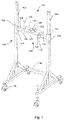
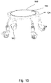
- Fig. 1 shows a chromatography column frame 101 comprising at least two legs 102, which are substantially vertical and arranged in parallel.
- a support arrangement 104 is connected to the legs 102 and a holder means 106 is connected to the support arrangement 104.
- the disclosed embodiment of the frame 101 in fig. 1 is constructed of elongated steel tubes which have a square cross section. It is however also possible to design the frame 101 in other materials having other cross sections, for example a circular cross section.
- the support arrangement 104 comprises two substantially identical brackets 108 provided with a first and second connection means 112.
- the first connection means 110 is arranged to connect the bracket 108 with one of the legs 102 of the frame 101, and the second connection means 112 is arranged to be connected to the holder means 106.
- the support arrangement 104 is adjustable along said legs 102, so that the frame 101 may be adapted for chromatography columns of different sizes. Therefore, the first connection means 110 of the support arrangement 104 is releasably connected to the leg 102 by means of fastening elements 114. Wheels 116 are arranged on the frame 101, so that the frame 101 may be easily moved to and from the position of the chromatography column 128. The wheels 116 are lockable, so that the frame 101 is prohibited from moving on the floor surface when the wheels 116 are locked. A cross bar 118 is arranged between the legs 102 in order to increase the stabilisation of the frame 101.
- the holder means 106 comprises at least one support plate 120 provided with a recess 122 and a bearing surface 124.
- a support plate 120 provided with a recess 122 and a bearing surface 124.
- two support plates 120 are arranged on the support arrangement 104, each plate is provided with a recess 122, which recesses 122 together define a substantially circular opening and a circular bearing surface 124 around the opening.
- At least one of the support plates 120 is removably connected to the second connection means 112 of the support arrangement 104 by means of fasteners 126, such as bolts or the like.
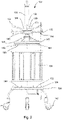
- Fig. 2 shows a side view of a chromatography column 128 with parts demounted and arranged at a distance from each others.
- the chromatography column 128 comprises a tubular housing 130, a first end unit 132 and a second end unit 134, when secured together to form a fluid tight seal by means of tension bolts 136.
- the first and second end units 132, 134 are removably connected to the tubular housing 130 by means of the tension bolts 136.
- the tubular housing 130 and end units 132, 134 are typically composed of stainless steel or a high-strength plastic material such as polypropylene.
- the material is biologically inert such that it does not elicit an immune response in humans in accordance with United States Pharmacopia (USP) ⁇ 88> class VI.
- An adaptor rod 138 extends through an opening 140 in the first end unit 132 and into the tubular housing 130.
- the column 128 is arranged on supporting wheels 142, so that the column 128 may be easily moved to a suitable position on a floor. Instead of arranging the supporting wheels 142 directly on the second end unit 134 it is possible to provide a support trolley (not disclosed) with wheels in a position under the column 128.
- An adaptor 141 which is connected to the adaptor rod 138, has a substantially circular shape provided with a sealing ring 144 on a peripheral outer surface 146, which is arranged to seal against the inner surface of the tubular housing 130 of the chromatography column 128.
- an operating means 148 When lowering the adaptor 141 by means of an operating means 148, the packing material within the tubular housing 130 will be compressed and packed.
- the adaptor rod 138 is provided with an external thread 150 and the operating means 148 is a threaded collar 152 provided with handles 154 for manually pivoting of the collar 152.
- the adaptor rod 138 When pivoting the collar 152 the adaptor rod 138 will be displaced by means of the external thread 150 on the rod 138 and the internal thread 153 of the collar 152.
- the compression force and downward movement of the adaptor 141 in the tubular housing 130 is thus achieved by forcing the adaptor rod 138 downward by pivoting the collar 152.
- a distributor plate 158 and a chromatography column filter 160 are mounted on the adaptor 141 and on the second end unit 134.
- the chromatography column filter 160 comprising, a porous, perforated net element through which fluid and particles up to a predetermined size are allowed to pass. Maintenance and cleaning of the filter 160 and the distributor plate 158 are necessary and therefore the filter 160 and the distributor plate 158 are preferably removably fixated to the adaptor 141 and to the second end unit 134.
- Fig. 3 shows a schematic section view of the chromatography column 128 in fig. 1 .
- the tubular housing 130, the second end unit 134 and the adaptor 141 form a bed space 162, which space is fluid tight and capable of withstanding high operating pressures.
- a wide range of column capacities is possible, typically ranging from 0.1 to 2000 liters.
- the bed space 162 is filled with a bed 164 of packing material, which is usually particulate in nature and consists of a porous medium.
- a liquid mobile phase is arranged to enter through an inlet 166 at the end of the adaptor rod 138 and flows through a central channel 168 in the adaptor rod 138 and further to the adaptor 141.
- the liquid mobile phase thereafter moves through the bed 164 of packing material and is finally removed via an outlet 170 in the second end unit 134.
- the porous medium enclosed in the column 128 as a packed bed 164 is generally formed by consolidating a suspension of discrete particles, known as slurry that is pumped or poured into the column 128 when the first end unit 132 and the adaptor have been removed from the tubular housing 130.
- the bed 164 of packed particulate medium is obtained by the downward movement of the adaptor 141 to compress the bed 164 between the adaptor 141 and the second end unit 134.
- the compression force and downward movement of the adaptor 141 is achieved by forcing the adaptor rod 138 downward by using an operating means 148, which may be manually, electrically, hydraulically or pneumatically operated.
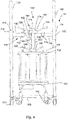
- Fig. 4 shows a side view of a chromatography column 128 arranged in the frame 101 according to the invention.
- the holder means 106 is arranged to releasably hold the adaptor rod 138 of the chromatography column 128, so that the adaptor rod 138 is prevented to move in a horizontal direction and so the adaptor rod 138 is allowed to move in a vertical direction.
- This is achieved by the circular recess 122 formed by the two support plates 120 of the holder means 106.
- the recess 122 defines an opening for the adaptor rod 138 and the opening therefore has a larger dimension than the dimension of the adaptor rod 138.
- At least one of the support plates 120 is removably connected to the support arrangement 104 by means of fasteners 126, such as bolts or the like. Therefore, one of the support plates 120 is dismounted from the brackets 108 of the support arrangement 104 when positioning the column 128 into the frame 101.
- the support plate 120 is mounted on the brackets 108 of the support arrangement 104 and the adaptor rod 138 of the column 128 is horizontally fixed by means of the support plates 120.
- the support plates 120 are provided with a bearing surface 124 for a driving means 172 arranged on the adaptor rod 138.
- the driving means 172 is a threaded sleeve 174 provided with handles 176 arranged to interact with the threads 150 on the adaptor rod 138, so that the adaptor rod 138 moves in the vertical direction when pivoting the sleeve 174.
- a stopper means 178 is arranged on the support arrangement 104, which stopper means 178 is adapted to interact with an axial groove 180 in the adaptor rod 138, so that the adaptor rod 138 is prevented from pivoting in said holder means 106 when the sleeve 174 is pivoted.
- the stopper means 178 is arranged on one of the support plates 120.
- the method of conducting maintenance on and packing of a chromatography column 128 according to the invention comprises the steps of providing a chromatography column 128 and the frame 101 according to the invention. Thereafter, the first end unit 132 or the second end unit 134 is disconnected from the tubular housing 130 depending on the type of maintenance which should be performed or if the column 128 should be filed with packing material. The disconnection is achieved by removing the tension bolts 160 which connect the end units 132, 134 to the tubular housing 130.
- the adaptor rod 138 is positioned in the holder means 106, so that the adaptor rod 138 is prevented from moving in a horizontal direction and so the adaptor rod 138 is allowed to move in a vertical direction.
- the driving means 172 is arranged on the adaptor rod 138 and the driving means 172 is activated, so that the adaptor rod 138 together with the first end unit 132 and the adaptor assembly 141 move vertically upwards , thereby separating the first end unit 132 and the adaptor assembly 141 from the tubular housing 130 or separating the first end unit 132, the adaptor assembly 141 and the tubular housing 130 from the second end unit 134 depending on the type of maintenance which should be performed or if the column 128 should be filed with packing material.
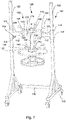
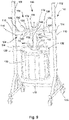
- the first end unit 132 and the adaptor assembly 141 have been lifted vertically upwards from the tubular housing 130 by means of the threaded sleeve 174. Since the tubular housing 130 together with the second end unit 134 rest on supporting wheels 142 it is easy to withdraw the tubular housing 130 and the second end unit 134 from the frame 101. Alternatively, the frame 101 may be withdrawn from the tubular housing 130 and the second end unit 134 by means of the wheels 116 on the frame 101. The tubular housing 130 and the second end unit 134 may thereafter be displaced to a maintenance area for replacing or cleaning the filter. Alternatively, the first end unit 132 and the adaptor assembly 141 may be displaced to a maintenance area for replacing or cleaning the filter.
- the tubular housing 130 together with the second end unit 134 resting on supporting wheels 142 are disclosed.
- packing material may be supplied into the tubular housing 130.
- the tubular housing 130 together with the second end unit 134 rest are moved on the supporting wheels 142 back to the frame 101 and the driving means 172 is activated, so that the adaptor rod 138 together with the first end unit 132 and the adaptor assembly 141 move vertically downwards for positioning the first end unit 132 and the adaptor assembly 141 to and into the tubular housing 130.
- the first end unit 132 is connected to the tubular housing 130 and the packing material is compressed in the column 128 by means of the operating means 148 on the adaptor assembly 141.
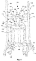
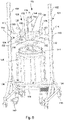
- Fig. 9 shows how the first end unit 132, the adaptor assembly 141 and also the tubular housing 130 have been lifted vertically upwards from the second end unit 134. Since the second end unit rests on supporting wheels 142 it is easy to withdraw the second end unit 134 from the frame 101. The second end unit 134 may thereafter be displaced to a maintenance area for replacing or cleaning the filter. Before the tubular housing 130 have been lifted vertically upwards from the second end unit 134, the tension bolts 160 which connect the second end 134 unit to the tubular housing 130 are removed.
- parts and surfaces being in contact with a process fluid are suitably selected from materials that are in accordance with typical material requirements in (bio- )pharmaceutical manufacturing or food grade quality.
- materials are suitably in compliance with USP Class VI and 21 CFR 177. Furthermore they are suitably of animal-free origin and compliance to EMEA/41 O/01. Features and components of the different embodiments above may be combined within the scope of the claims.
Landscapes
- Chemical & Material Sciences (AREA)
- Analytical Chemistry (AREA)
- Physics & Mathematics (AREA)
- Health & Medical Sciences (AREA)
- Life Sciences & Earth Sciences (AREA)
- Biochemistry (AREA)
- General Health & Medical Sciences (AREA)
- General Physics & Mathematics (AREA)
- Immunology (AREA)
- Pathology (AREA)
- Chemical Kinetics & Catalysis (AREA)
- Treatment Of Liquids With Adsorbents In General (AREA)
Claims (15)
- Cadre de maintenance (101), adapté pour lever au moins une unité d'extrémité (132) d'une colonne de chromatographie (128) par l'intermédiaire d'une tige adaptatrice (138) de la colonne (128), le cadre comprenant :au moins deux pieds (102) ;un agencement de support (104) connecté auxdits au moins deux pieds (102) ;un moyen de maintien (106) connecté audit agencement de support (104) ;dans lequel ledit moyen de maintien (106) est agencé pour maintenir de manière amovible la tige adaptatrice (138) de la colonne de chromatographie (128), de sorte que la tige adaptatrice (138) est empêchée de se déplacer dans une direction horizontale et ainsi la tige adaptatrice (138) est autorisée à se déplacer dans une direction verticale pour ledit levage ; et dans lequel :
un moyen de butée (178) est agencé sur l'agencement de support (104), caractérisé en ce que le moyen de butée (178) est adapté pour interagir avec une rainure axiale (180) dans la tige adaptatrice (138), de sorte que la tige adaptatrice (138) est empêchée de pivoter dans ledit moyen de maintien (106). - Cadre (101) selon la revendication 1, caractérisé en ce que le moyen de maintien (106) comprend au moins une plaque de support (120) pourvue d'un évidement (122) pour la tige adaptatrice (138).
- Cadre (101) selon la revendication 2,
caractérisé en ce que l'au moins une plaque de support (120) est pourvue d'une surface d'appui (124) pour un moyen d'entraînement (172) agencé sur la tige adaptatrice (138). - Cadre (101) selon la revendication 3, caractérisé en ce que le moyen d'entraînement (172) est un manchon fileté (174) agencé pour interagir avec des filetages (150) sur la tige adaptatrice (138), de sorte que la tige adaptatrice (138) se déplace dans la direction verticale lors du pivotement du manchon (174).
- Cadre (101) selon l'une quelconque des revendications 2-4, caractérisé en ce que deux plaques de support (120) sont agencées sur l'agencement de support (104), chaque plaque (120) est pourvue d'un évidement (122), lesquels évidements (122) définissent conjointement une ouverture pour la tige adaptatrice (138).
- Cadre (101) selon la revendication 5, caractérisé en ce qu'au moins une des plaques de support (120) est connectée de manière amovible à l'agencement de support (104).
- Cadre (101) selon l'une quelconque des revendications précédentes, caractérisé en outre par une barre transversale (118) agencée entre les pieds (102).
- Cadre (101) selon l'une quelconque des revendications précédentes, caractérisé en ce que l'agencement de support (104) est ajustable le long desdits pieds (102), de sorte que le cadre (101) peut être adapté pour des colonnes de chromatographie (128) de différentes tailles.
- Cadre (101) selon l'une quelconque des revendications précédentes, caractérisé en ce que des roues (116) sont agencées sur le cadre (101), de sorte que le cadre (101) peut être déplacé vers et depuis la position de la colonne de chromatographie (128).
- Cadre (101) selon la revendication 5,
ou toute revendication lorsqu'elle en dépend, caractérisé en outre en ce que le moyen de butée (178) est agencé sur l'une des plaques de support (120). - Procédé de réalisation de maintenance et de garnissage d'une colonne de chromatographie (128) comprenant les étapes consistant à :a) fournir une colonne de chromatographie (128) comprenant ;un boîtier tubulaire (130) ;une première unité d'extrémité (132) connectée de manière amovible à une première extrémité du boîtier tubulaire (130) ;une seconde unité d'extrémité (134) connectée de manière amovible à une seconde extrémité du boîtier tubulaire (130) ;un ensemble adaptateur (141) pouvant être déplacé au sein dudit boîtier tubulaire (130) ;une tige adaptatrice (138) connectée audit ensemble adaptateur (141), laquelle tige adaptatrice (138) est agencée pour s'étendre à travers une ouverture (140) dans la première unité d'extrémité (132) ;b) fournir un cadre de maintenance (101) selon l'une quelconque des revendications précédentes ;c) déconnecter la première unité d'extrémité (132) ou la seconde unité d'extrémité (134) du boîtier tubulaire (130) ;d) positionner la tige adaptatrice (138) dans ledit moyen de maintien (106), de sorte que la tige adaptatrice (138) est empêchée de se déplacer dans une direction horizontale et ainsi la tige adaptatrice (138) est autorisée à se déplacer dans une direction verticale ;e) agencer un moyen d'entraînement (172) sur la tige adaptatrice (138) ;f) actionner le moyen d'entraînement (172), de sorte que la tige adaptatrice (138) conjointement avec la première unité d'extrémité (132) et l'ensemble adaptateur (141) se déplacent verticalement vers le haut, séparant ainsi la première unité d'extrémité (132) et l'ensemble adaptateur (141) du boîtier tubulaire (130) ou séparant la première unité d'extrémité (132), l'ensemble adaptateur (141) et le boîtier tubulaire (130) de la seconde unité d'extrémité (134).
- Procédé selon la revendication 11, caractérisé par l'étape supplémentaire consistant à :
g) réaliser la maintenance de la colonne de chromatographie (128). - Procédé selon l'une quelconque des revendications 11 ou 12, caractérisé par l'étape supplémentaire consistant à :
h) fournir un matériau de garnissage dans le boîtier tubulaire (130), lorsque le boîtier tubulaire (130) est connecté à la seconde unité d'extrémité (134). - Procédé selon la revendication 13, caractérisé par l'étape supplémentaire consistant à :i) actionner le moyen d'entraînement (172), de sorte que la tige adaptatrice (138) conjointement avec la première unité d'extrémité (132) et l'ensemble adaptateur (141) se déplacent verticalement vers le bas pour positionner la première unité d'extrémité (132) et l'ensemble adaptateur (141) vers et dans le boîtier tubulaire (130) ;j) connecter la première unité d'extrémité (132) au boîtier tubulaire (130) ;k) comprimer le matériau de garnissage dans la colonne (128) au moyen de l'ensemble adaptateur (141).
- Procédé selon l'une quelconque des revendications 11-14, caractérisé par l'étape supplémentaire consistant à :
l) fournir au moins une roue de support (170) dans une position sous la colonne (128).
Applications Claiming Priority (2)
| Application Number | Priority Date | Filing Date | Title |
|---|---|---|---|
| CN201210236219.2A CN103505909B (zh) | 2012-06-21 | 2012-06-21 | 层析柱框架和对层析柱进行维护和填充的方法 |
| PCT/SE2013/050744 WO2013191641A1 (fr) | 2012-06-21 | 2013-06-20 | Cadre de colonne de chromatographie et procédé d'entretien et de remplissage de colonne de chromatographie |
Publications (3)
| Publication Number | Publication Date |
|---|---|
| EP2864778A1 EP2864778A1 (fr) | 2015-04-29 |
| EP2864778A4 EP2864778A4 (fr) | 2016-06-08 |
| EP2864778B1 true EP2864778B1 (fr) | 2023-01-18 |
Family
ID=49769113
Family Applications (1)
| Application Number | Title | Priority Date | Filing Date |
|---|---|---|---|
| EP13807156.8A Active EP2864778B1 (fr) | 2012-06-21 | 2013-06-20 | Cadre de colonne de chromatographie et procédé d'entretien et de remplissage de colonne de chromatographie |
Country Status (5)
| Country | Link |
|---|---|
| US (2) | US9566538B2 (fr) |
| EP (1) | EP2864778B1 (fr) |
| JP (1) | JP6224702B2 (fr) |
| CN (1) | CN103505909B (fr) |
| WO (1) | WO2013191641A1 (fr) |
Families Citing this family (14)
| Publication number | Priority date | Publication date | Assignee | Title |
|---|---|---|---|---|
| CN103505909B (zh) | 2012-06-21 | 2018-02-13 | 通用电气健康护理生物科学股份公司 | 层析柱框架和对层析柱进行维护和填充的方法 |
| JP6540696B2 (ja) | 2013-07-09 | 2019-07-17 | ジーイー・ヘルスケア・バイオサイエンス・アクチボラグ | カラム用構成物、かかるカラム用構成物において管状ハウジングを交換する方法 |
| CN104436757B (zh) * | 2014-11-26 | 2017-10-27 | 源创精科生物科技(长沙)有限公司 | 压力耦合式层析柱流体分配器 |
| DE102016123457B4 (de) * | 2016-12-05 | 2026-02-19 | Dionex Softron Gmbh | Basis zum Umschalten eines Geräts zwischen einem verschiebbaren und einem nicht verschiebbaren Zustand |
| EP3381530A1 (fr) * | 2017-03-29 | 2018-10-03 | EMD Millipore Corporation | Installation de traitement de liquide biologique |
| CN106984066A (zh) * | 2017-06-06 | 2017-07-28 | 利穗科技(苏州)有限公司 | 一种层析柱维护柱架 |
| CN107982961A (zh) * | 2018-01-08 | 2018-05-04 | 湖南科众源创科技有限公司 | 动梁式全自动层析柱 |
| US11745119B2 (en) * | 2018-04-16 | 2023-09-05 | Asahi Kasei Bioprocess America, Inc. | Chromatography and synthesis column apparatus and method of assembly |
| CN110393947B (zh) * | 2019-09-04 | 2024-03-26 | 广东省生物工程研究所(广州甘蔗糖业研究所) | 一种层析柱装置和层析柱的制备方法 |
| CN111569468A (zh) * | 2020-06-15 | 2020-08-25 | 江苏汉邦科技有限公司 | 一种层析柱维护装置 |
| GB202018386D0 (en) * | 2020-11-23 | 2021-01-06 | Cytiva Sweden Ab | Apparatus for bio-product processing |
| FR3132446A1 (fr) * | 2022-02-08 | 2023-08-11 | L'air Liquide Societe Anonyme Pour L'etude Et L'exploitation Des Procedes Georges Claude | Dispositif d’insertion d’un tronçon de garnissage |
| CN114768302B (zh) * | 2022-06-14 | 2022-09-16 | 山东惠民中联生物科技有限公司 | 一种膏剂驱鸟剂制备过程中层析装置 |
| CN115445243B (zh) * | 2022-10-08 | 2023-08-01 | 苏州博进生物技术有限公司 | 用于层析柱的高密封性密封结构 |
Citations (4)
| Publication number | Priority date | Publication date | Assignee | Title |
|---|---|---|---|---|
| US5667675A (en) * | 1996-02-29 | 1997-09-16 | Varian Associate, Inc. | Collapsible apparatus for compressing packing material in liquid chromatography columns and methods of use |
| EP1481241A1 (fr) * | 2002-03-04 | 2004-12-01 | Millipore Corporation | Modele ameliore de colonne chromatographique |
| US20060091052A1 (en) * | 2004-11-02 | 2006-05-04 | Per Uselius | Chromatography column |
| EP2324898A2 (fr) * | 2009-11-23 | 2011-05-25 | Agilent Technologies, Inc. | Appareil et procédés pour conditionner les colonnes de chromatographie |
Family Cites Families (24)
| Publication number | Priority date | Publication date | Assignee | Title |
|---|---|---|---|---|
| DE3833300A1 (de) * | 1988-09-30 | 1990-04-05 | Claude Marchand | Chromatographiesaeulen-abschlusseinrichtung |
| GB2248028A (en) * | 1990-09-19 | 1992-03-25 | Amicon Ltd | Improved chromatography column. |
| US5213683A (en) * | 1991-08-08 | 1993-05-25 | Chromaflow, Inc. | Apparatus for charging and discharging of chromatography column bed |
| US5462659A (en) * | 1993-06-15 | 1995-10-31 | Sepragen Corporation | Chromatography column |
| DE69729828T2 (de) * | 1996-02-29 | 2005-07-14 | Varian, Inc., Palo Alto | Zusammenschiebbare vorrichtung zur kompression von packungsmaterial in flüssigkeitschromatographiekolonnen und verfahren zu ihrer benutzung |
| GB2325418B (en) * | 1997-05-23 | 2001-04-11 | Millipore Corp | Chromatographic column and valve |
| US5951873A (en) * | 1997-12-23 | 1999-09-14 | Modcol Corporation | Chromatographic device with piston locking mechanism and method of packing same |
| US6139732A (en) * | 1998-03-16 | 2000-10-31 | Hodge Bioseparation, Ltd. | Chromatography column |
| US6736974B1 (en) * | 2001-11-02 | 2004-05-18 | Mann Welding Company | Chromatography column and method of operation |
| WO2003074526A2 (fr) * | 2002-02-28 | 2003-09-12 | Mallinckrodt Inc. | Procede et systeme de separation et de purification d'au moins un alcaloide narcotique au moyen d'une chromatographie preparative en phase inversee |
| US7041216B2 (en) | 2003-02-24 | 2006-05-09 | Millipore Corporation | Chromatography column |
| GB0328674D0 (en) * | 2003-12-10 | 2004-01-14 | Euroflow Uk Ltd | Chromatography columns and their operation |
| US7238282B2 (en) * | 2005-03-04 | 2007-07-03 | Millipore Corporation | System for automated compression of chromatography columns |
| CA2670542C (fr) * | 2006-12-13 | 2014-08-26 | Bio-Rad Laboratories, Inc. | Structures de support pour des colonnes de chromatographie preparative |
| US7780853B2 (en) * | 2007-06-15 | 2010-08-24 | Ge Healthcare Bio-Sciences Ab | Method for conducting maintenance on a chromatography column |
| US7785473B2 (en) * | 2007-06-15 | 2010-08-31 | Ge Healthcare Bio-Sciences Ab | Chromatography column and method of maintenance |
| US7708891B2 (en) * | 2007-06-15 | 2010-05-04 | Ge Healthcare Bio-Sciences Ab | Chromatography column and method of maintenance |
| EP2245449B1 (fr) * | 2008-02-21 | 2015-12-02 | All-Tech Associates Inc. | Appareil de remplissage de colonne et procédé de réalisation et d'utilisation de celui-ci |
| US8246833B2 (en) | 2009-12-17 | 2012-08-21 | Ge Healthcare Bio-Sciences Ab | Chromatography column and maintenance method |
| EP2585186B1 (fr) * | 2010-06-23 | 2017-01-18 | GE Healthcare Bio-Sciences AB | Procédé permettant d'effectuer l'entretien sur une colonne de chromatographie |
| GB2485837A (en) * | 2010-11-29 | 2012-05-30 | Ge Healthcare Bio Sciences Ab | Securing a distributor plate of a chromatography column by generating a vacuum |
| US8663477B2 (en) * | 2012-06-21 | 2014-03-04 | Ge Healthcare Bio-Sciences Ab | Chromatography column stand |
| CN103505909B (zh) | 2012-06-21 | 2018-02-13 | 通用电气健康护理生物科学股份公司 | 层析柱框架和对层析柱进行维护和填充的方法 |
| US10393709B2 (en) * | 2014-04-12 | 2019-08-27 | Ge Healthcare Bio-Sciences Ab | Hoisting and holding system for chromatography column |
-
2012
- 2012-06-21 CN CN201210236219.2A patent/CN103505909B/zh active Active
-
2013
- 2013-06-20 EP EP13807156.8A patent/EP2864778B1/fr active Active
- 2013-06-20 WO PCT/SE2013/050744 patent/WO2013191641A1/fr not_active Ceased
- 2013-06-20 JP JP2015518379A patent/JP6224702B2/ja active Active
- 2013-06-21 US US14/409,446 patent/US9566538B2/en active Active
-
2017
- 2017-01-16 US US15/407,238 patent/US10184923B2/en active Active
Patent Citations (4)
| Publication number | Priority date | Publication date | Assignee | Title |
|---|---|---|---|---|
| US5667675A (en) * | 1996-02-29 | 1997-09-16 | Varian Associate, Inc. | Collapsible apparatus for compressing packing material in liquid chromatography columns and methods of use |
| EP1481241A1 (fr) * | 2002-03-04 | 2004-12-01 | Millipore Corporation | Modele ameliore de colonne chromatographique |
| US20060091052A1 (en) * | 2004-11-02 | 2006-05-04 | Per Uselius | Chromatography column |
| EP2324898A2 (fr) * | 2009-11-23 | 2011-05-25 | Agilent Technologies, Inc. | Appareil et procédés pour conditionner les colonnes de chromatographie |
Also Published As
| Publication number | Publication date |
|---|---|
| US10184923B2 (en) | 2019-01-22 |
| WO2013191641A1 (fr) | 2013-12-27 |
| US9566538B2 (en) | 2017-02-14 |
| CN103505909A (zh) | 2014-01-15 |
| EP2864778A1 (fr) | 2015-04-29 |
| EP2864778A4 (fr) | 2016-06-08 |
| JP6224702B2 (ja) | 2017-11-01 |
| US20170122919A1 (en) | 2017-05-04 |
| JP2015526706A (ja) | 2015-09-10 |
| US20150198568A1 (en) | 2015-07-16 |
| CN103505909B (zh) | 2018-02-13 |
Similar Documents
| Publication | Publication Date | Title |
|---|---|---|
| US10184923B2 (en) | Chromatography column frame and method of conducting maintenance on and packing of a chromatography column | |
| JP5164475B2 (ja) | クロマトグラフィーカラムの保守を行うための方法 | |
| US10307692B2 (en) | Chromatography column and method of conducting maintenance on a chromatography column | |
| CA2690663C (fr) | Colonne de chromatographie et procede de maintenance | |
| US8394276B2 (en) | Chromatography column and maintenance method | |
| US7708891B2 (en) | Chromatography column and method of maintenance | |
| US7785473B2 (en) | Chromatography column and method of maintenance | |
| CA2597448A1 (fr) | Colonne chromatographique et methode de maintenance | |
| CA2592247C (fr) | Colonne chromatographique et methode de maintenance |
Legal Events
| Date | Code | Title | Description |
|---|---|---|---|
| PUAI | Public reference made under article 153(3) epc to a published international application that has entered the european phase |
Free format text: ORIGINAL CODE: 0009012 |
|
| 17P | Request for examination filed |
Effective date: 20150116 |
|
| AK | Designated contracting states |
Kind code of ref document: A1 Designated state(s): AL AT BE BG CH CY CZ DE DK EE ES FI FR GB GR HR HU IE IS IT LI LT LU LV MC MK MT NL NO PL PT RO RS SE SI SK SM TR |
|
| AX | Request for extension of the european patent |
Extension state: BA ME |
|
| DAX | Request for extension of the european patent (deleted) | ||
| RIC1 | Information provided on ipc code assigned before grant |
Ipc: B01D 15/22 20060101ALI20160107BHEP Ipc: B01D 15/20 20060101ALI20160107BHEP Ipc: G01N 30/56 20060101ALI20160107BHEP Ipc: G01N 30/60 20060101AFI20160107BHEP |
|
| RA4 | Supplementary search report drawn up and despatched (corrected) |
Effective date: 20160511 |
|
| RIC1 | Information provided on ipc code assigned before grant |
Ipc: G01N 30/56 20060101ALI20160504BHEP Ipc: G01N 30/60 20060101AFI20160504BHEP Ipc: B01D 15/22 20060101ALI20160504BHEP Ipc: B01D 15/20 20060101ALI20160504BHEP |
|
| RAP1 | Party data changed (applicant data changed or rights of an application transferred) |
Owner name: CYTIVA SWEDEN AB |
|
| STAA | Information on the status of an ep patent application or granted ep patent |
Free format text: STATUS: EXAMINATION IS IN PROGRESS |
|
| 17Q | First examination report despatched |
Effective date: 20200827 |
|
| GRAP | Despatch of communication of intention to grant a patent |
Free format text: ORIGINAL CODE: EPIDOSNIGR1 |
|
| STAA | Information on the status of an ep patent application or granted ep patent |
Free format text: STATUS: GRANT OF PATENT IS INTENDED |
|
| RIC1 | Information provided on ipc code assigned before grant |
Ipc: B01D 15/22 20060101ALI20220819BHEP Ipc: B01D 15/20 20060101ALI20220819BHEP Ipc: B01D 15/10 20060101ALI20220819BHEP Ipc: G01N 30/56 20060101ALI20220819BHEP Ipc: G01N 30/60 20060101AFI20220819BHEP |
|
| INTG | Intention to grant announced |
Effective date: 20220926 |
|
| GRAS | Grant fee paid |
Free format text: ORIGINAL CODE: EPIDOSNIGR3 |
|
| GRAA | (expected) grant |
Free format text: ORIGINAL CODE: 0009210 |
|
| STAA | Information on the status of an ep patent application or granted ep patent |
Free format text: STATUS: THE PATENT HAS BEEN GRANTED |
|
| AK | Designated contracting states |
Kind code of ref document: B1 Designated state(s): AL AT BE BG CH CY CZ DE DK EE ES FI FR GB GR HR HU IE IS IT LI LT LU LV MC MK MT NL NO PL PT RO RS SE SI SK SM TR |
|
| REG | Reference to a national code |
Ref country code: GB Ref legal event code: FG4D |
|
| REG | Reference to a national code |
Ref country code: CH Ref legal event code: EP |
|
| REG | Reference to a national code |
Ref country code: DE Ref legal event code: R096 Ref document number: 602013083237 Country of ref document: DE |
|
| REG | Reference to a national code |
Ref country code: AT Ref legal event code: REF Ref document number: 1544976 Country of ref document: AT Kind code of ref document: T Effective date: 20230215 Ref country code: IE Ref legal event code: FG4D |
|
| REG | Reference to a national code |
Ref country code: LT Ref legal event code: MG9D |
|
| REG | Reference to a national code |
Ref country code: NL Ref legal event code: MP Effective date: 20230118 |
|
| REG | Reference to a national code |
Ref country code: AT Ref legal event code: MK05 Ref document number: 1544976 Country of ref document: AT Kind code of ref document: T Effective date: 20230118 |
|
| PG25 | Lapsed in a contracting state [announced via postgrant information from national office to epo] |
Ref country code: NL Free format text: LAPSE BECAUSE OF FAILURE TO SUBMIT A TRANSLATION OF THE DESCRIPTION OR TO PAY THE FEE WITHIN THE PRESCRIBED TIME-LIMIT Effective date: 20230118 |
|
| P01 | Opt-out of the competence of the unified patent court (upc) registered |
Effective date: 20230526 |
|
| PG25 | Lapsed in a contracting state [announced via postgrant information from national office to epo] |
Ref country code: RS Free format text: LAPSE BECAUSE OF FAILURE TO SUBMIT A TRANSLATION OF THE DESCRIPTION OR TO PAY THE FEE WITHIN THE PRESCRIBED TIME-LIMIT Effective date: 20230118 Ref country code: PT Free format text: LAPSE BECAUSE OF FAILURE TO SUBMIT A TRANSLATION OF THE DESCRIPTION OR TO PAY THE FEE WITHIN THE PRESCRIBED TIME-LIMIT Effective date: 20230518 Ref country code: NO Free format text: LAPSE BECAUSE OF FAILURE TO SUBMIT A TRANSLATION OF THE DESCRIPTION OR TO PAY THE FEE WITHIN THE PRESCRIBED TIME-LIMIT Effective date: 20230418 Ref country code: LV Free format text: LAPSE BECAUSE OF FAILURE TO SUBMIT A TRANSLATION OF THE DESCRIPTION OR TO PAY THE FEE WITHIN THE PRESCRIBED TIME-LIMIT Effective date: 20230118 Ref country code: LT Free format text: LAPSE BECAUSE OF FAILURE TO SUBMIT A TRANSLATION OF THE DESCRIPTION OR TO PAY THE FEE WITHIN THE PRESCRIBED TIME-LIMIT Effective date: 20230118 Ref country code: HR Free format text: LAPSE BECAUSE OF FAILURE TO SUBMIT A TRANSLATION OF THE DESCRIPTION OR TO PAY THE FEE WITHIN THE PRESCRIBED TIME-LIMIT Effective date: 20230118 Ref country code: ES Free format text: LAPSE BECAUSE OF FAILURE TO SUBMIT A TRANSLATION OF THE DESCRIPTION OR TO PAY THE FEE WITHIN THE PRESCRIBED TIME-LIMIT Effective date: 20230118 Ref country code: AT Free format text: LAPSE BECAUSE OF FAILURE TO SUBMIT A TRANSLATION OF THE DESCRIPTION OR TO PAY THE FEE WITHIN THE PRESCRIBED TIME-LIMIT Effective date: 20230118 |
|
| PG25 | Lapsed in a contracting state [announced via postgrant information from national office to epo] |
Ref country code: SE Free format text: LAPSE BECAUSE OF FAILURE TO SUBMIT A TRANSLATION OF THE DESCRIPTION OR TO PAY THE FEE WITHIN THE PRESCRIBED TIME-LIMIT Effective date: 20230118 Ref country code: PL Free format text: LAPSE BECAUSE OF FAILURE TO SUBMIT A TRANSLATION OF THE DESCRIPTION OR TO PAY THE FEE WITHIN THE PRESCRIBED TIME-LIMIT Effective date: 20230118 Ref country code: IS Free format text: LAPSE BECAUSE OF FAILURE TO SUBMIT A TRANSLATION OF THE DESCRIPTION OR TO PAY THE FEE WITHIN THE PRESCRIBED TIME-LIMIT Effective date: 20230518 Ref country code: GR Free format text: LAPSE BECAUSE OF FAILURE TO SUBMIT A TRANSLATION OF THE DESCRIPTION OR TO PAY THE FEE WITHIN THE PRESCRIBED TIME-LIMIT Effective date: 20230419 Ref country code: FI Free format text: LAPSE BECAUSE OF FAILURE TO SUBMIT A TRANSLATION OF THE DESCRIPTION OR TO PAY THE FEE WITHIN THE PRESCRIBED TIME-LIMIT Effective date: 20230118 |
|
| REG | Reference to a national code |
Ref country code: DE Ref legal event code: R097 Ref document number: 602013083237 Country of ref document: DE |
|
| PG25 | Lapsed in a contracting state [announced via postgrant information from national office to epo] |
Ref country code: SM Free format text: LAPSE BECAUSE OF FAILURE TO SUBMIT A TRANSLATION OF THE DESCRIPTION OR TO PAY THE FEE WITHIN THE PRESCRIBED TIME-LIMIT Effective date: 20230118 Ref country code: RO Free format text: LAPSE BECAUSE OF FAILURE TO SUBMIT A TRANSLATION OF THE DESCRIPTION OR TO PAY THE FEE WITHIN THE PRESCRIBED TIME-LIMIT Effective date: 20230118 Ref country code: EE Free format text: LAPSE BECAUSE OF FAILURE TO SUBMIT A TRANSLATION OF THE DESCRIPTION OR TO PAY THE FEE WITHIN THE PRESCRIBED TIME-LIMIT Effective date: 20230118 Ref country code: DK Free format text: LAPSE BECAUSE OF FAILURE TO SUBMIT A TRANSLATION OF THE DESCRIPTION OR TO PAY THE FEE WITHIN THE PRESCRIBED TIME-LIMIT Effective date: 20230118 Ref country code: CZ Free format text: LAPSE BECAUSE OF FAILURE TO SUBMIT A TRANSLATION OF THE DESCRIPTION OR TO PAY THE FEE WITHIN THE PRESCRIBED TIME-LIMIT Effective date: 20230118 |
|
| PLBE | No opposition filed within time limit |
Free format text: ORIGINAL CODE: 0009261 |
|
| STAA | Information on the status of an ep patent application or granted ep patent |
Free format text: STATUS: NO OPPOSITION FILED WITHIN TIME LIMIT |
|
| PG25 | Lapsed in a contracting state [announced via postgrant information from national office to epo] |
Ref country code: SK Free format text: LAPSE BECAUSE OF FAILURE TO SUBMIT A TRANSLATION OF THE DESCRIPTION OR TO PAY THE FEE WITHIN THE PRESCRIBED TIME-LIMIT Effective date: 20230118 |
|
| 26N | No opposition filed |
Effective date: 20231019 |
|
| PG25 | Lapsed in a contracting state [announced via postgrant information from national office to epo] |
Ref country code: MC Free format text: LAPSE BECAUSE OF FAILURE TO SUBMIT A TRANSLATION OF THE DESCRIPTION OR TO PAY THE FEE WITHIN THE PRESCRIBED TIME-LIMIT Effective date: 20230118 |
|
| PG25 | Lapsed in a contracting state [announced via postgrant information from national office to epo] |
Ref country code: SI Free format text: LAPSE BECAUSE OF FAILURE TO SUBMIT A TRANSLATION OF THE DESCRIPTION OR TO PAY THE FEE WITHIN THE PRESCRIBED TIME-LIMIT Effective date: 20230118 Ref country code: MC Free format text: LAPSE BECAUSE OF FAILURE TO SUBMIT A TRANSLATION OF THE DESCRIPTION OR TO PAY THE FEE WITHIN THE PRESCRIBED TIME-LIMIT Effective date: 20230118 |
|
| REG | Reference to a national code |
Ref country code: CH Ref legal event code: PL |
|
| REG | Reference to a national code |
Ref country code: BE Ref legal event code: MM Effective date: 20230630 |
|
| PG25 | Lapsed in a contracting state [announced via postgrant information from national office to epo] |
Ref country code: LU Free format text: LAPSE BECAUSE OF NON-PAYMENT OF DUE FEES Effective date: 20230620 |
|
| REG | Reference to a national code |
Ref country code: IE Ref legal event code: MM4A |
|
| PG25 | Lapsed in a contracting state [announced via postgrant information from national office to epo] |
Ref country code: LU Free format text: LAPSE BECAUSE OF NON-PAYMENT OF DUE FEES Effective date: 20230620 |
|
| PG25 | Lapsed in a contracting state [announced via postgrant information from national office to epo] |
Ref country code: IE Free format text: LAPSE BECAUSE OF NON-PAYMENT OF DUE FEES Effective date: 20230620 |
|
| PG25 | Lapsed in a contracting state [announced via postgrant information from national office to epo] |
Ref country code: IE Free format text: LAPSE BECAUSE OF NON-PAYMENT OF DUE FEES Effective date: 20230620 Ref country code: CH Free format text: LAPSE BECAUSE OF NON-PAYMENT OF DUE FEES Effective date: 20230630 |
|
| PG25 | Lapsed in a contracting state [announced via postgrant information from national office to epo] |
Ref country code: IT Free format text: LAPSE BECAUSE OF FAILURE TO SUBMIT A TRANSLATION OF THE DESCRIPTION OR TO PAY THE FEE WITHIN THE PRESCRIBED TIME-LIMIT Effective date: 20230118 Ref country code: BE Free format text: LAPSE BECAUSE OF NON-PAYMENT OF DUE FEES Effective date: 20230630 |
|
| PG25 | Lapsed in a contracting state [announced via postgrant information from national office to epo] |
Ref country code: BG Free format text: LAPSE BECAUSE OF FAILURE TO SUBMIT A TRANSLATION OF THE DESCRIPTION OR TO PAY THE FEE WITHIN THE PRESCRIBED TIME-LIMIT Effective date: 20230118 |
|
| PG25 | Lapsed in a contracting state [announced via postgrant information from national office to epo] |
Ref country code: BG Free format text: LAPSE BECAUSE OF FAILURE TO SUBMIT A TRANSLATION OF THE DESCRIPTION OR TO PAY THE FEE WITHIN THE PRESCRIBED TIME-LIMIT Effective date: 20230118 |
|
| PGFP | Annual fee paid to national office [announced via postgrant information from national office to epo] |
Ref country code: DE Payment date: 20250626 Year of fee payment: 13 |
|
| PGFP | Annual fee paid to national office [announced via postgrant information from national office to epo] |
Ref country code: GB Payment date: 20250617 Year of fee payment: 13 |
|
| PGFP | Annual fee paid to national office [announced via postgrant information from national office to epo] |
Ref country code: FR Payment date: 20250624 Year of fee payment: 13 |
|
| PG25 | Lapsed in a contracting state [announced via postgrant information from national office to epo] |
Ref country code: CY Free format text: LAPSE BECAUSE OF FAILURE TO SUBMIT A TRANSLATION OF THE DESCRIPTION OR TO PAY THE FEE WITHIN THE PRESCRIBED TIME-LIMIT; INVALID AB INITIO Effective date: 20130620 |
|
| PG25 | Lapsed in a contracting state [announced via postgrant information from national office to epo] |
Ref country code: HU Free format text: LAPSE BECAUSE OF FAILURE TO SUBMIT A TRANSLATION OF THE DESCRIPTION OR TO PAY THE FEE WITHIN THE PRESCRIBED TIME-LIMIT; INVALID AB INITIO Effective date: 20130620 |
|
| PG25 | Lapsed in a contracting state [announced via postgrant information from national office to epo] |
Ref country code: TR Free format text: LAPSE BECAUSE OF FAILURE TO SUBMIT A TRANSLATION OF THE DESCRIPTION OR TO PAY THE FEE WITHIN THE PRESCRIBED TIME-LIMIT Effective date: 20230118 |