EP2864965B1 - Procédé d'élaboration, basée sur un modèle, de jeux de données d'essai pour le contrôle d'algorithmes de traitement d'image - Google Patents
Procédé d'élaboration, basée sur un modèle, de jeux de données d'essai pour le contrôle d'algorithmes de traitement d'image Download PDFInfo
- Publication number
- EP2864965B1 EP2864965B1 EP13709298.7A EP13709298A EP2864965B1 EP 2864965 B1 EP2864965 B1 EP 2864965B1 EP 13709298 A EP13709298 A EP 13709298A EP 2864965 B1 EP2864965 B1 EP 2864965B1
- Authority
- EP
- European Patent Office
- Prior art keywords
- image processing
- characterisation
- scene
- image
- vectors
- Prior art date
- Legal status (The legal status is an assumption and is not a legal conclusion. Google has not performed a legal analysis and makes no representation as to the accuracy of the status listed.)
- Not-in-force
Links
Images



Classifications
-
- G—PHYSICS
- G06—COMPUTING OR CALCULATING; COUNTING
- G06T—IMAGE DATA PROCESSING OR GENERATION, IN GENERAL
- G06T17/00—Three-dimensional [3D] modelling for computer graphics
-
- G—PHYSICS
- G06—COMPUTING OR CALCULATING; COUNTING
- G06T—IMAGE DATA PROCESSING OR GENERATION, IN GENERAL
- G06T15/00—Three-dimensional [3D] image rendering
- G06T15/10—Geometric effects
- G06T15/20—Perspective computation
-
- G—PHYSICS
- G06—COMPUTING OR CALCULATING; COUNTING
- G06T—IMAGE DATA PROCESSING OR GENERATION, IN GENERAL
- G06T7/00—Image analysis
- G06T7/0002—Inspection of images, e.g. flaw detection
- G06T7/0004—Industrial image inspection
- G06T7/001—Industrial image inspection using an image reference approach
Definitions
- the invention relates to a method for testing an image processing method by means of artificially generated test data sets.
- the invention is advantageously used in the field of analysis of image processing methods which extract certain features from existing digital images.
- An inventive method is advantageously used in the field of quality assurance and certification of image processing methods, especially in autonomous systems.
- test images are stored together with the expected comparison results, which are sometimes referred to as "ground truth", in common test data sets.
- the stored test images are fed to the image processing method to be validated.
- the results of the respective image processing method are compared after processing with the comparison results.
- Such a comparison of the results provided by the image processing method with the comparison results is performed for a plurality of test data sets.
- various image processing methods can be checked based on the same test data sets and the agreement with the respective comparison results are used as a measure of the quality of the respective image processing method.
- test data records In addition to the manual creation of test data sets, it is also possible to automatically generate test data records. With automatically generated test data sets, however, there is the problem of creating a number of test scenarios that ensure as complete a check as possible of the respective method. Nonnemaker and Baird use interpolated data in "Using Synthetic Data Safely in Classification" to create larger test data sets. Here it is shown that test records obtained in this way did not give worse results. However, it can often be required that critical situations, which occur only in very rare cases, are to be checked particularly intensively. In an automatic generation of test data sets such critical test data sets are often not taken into account, so that a test based on the automatically generated test data sets does not have much significance over the image processing method used in each case. It should be noted, however, that the manual creation of test data for critical situations is often not possible as it would be associated with endangering human life or public safety. Automated approaches avoid this risk in principle.
- test data sets Another disadvantage of automatically generated test data sets is that often redundant test data sets are generated whose evaluation has only little significance for the behavior of the image processing method used in each case.
- a very large number of data sets would have to be generated, of which a large number of largely identical requirements for the image processing method, with only very few critical situations being examined overall.
- image processing methods which solve tasks through the analysis of images and which form an important clue for the control of autonomous systems.
- One possible application of an image processing method is, for example, counting persons entering an area, identifying potentially dangerous contents in baggage, or automatically monitoring compliance with a selected lane.
- Another problem is to certify an image processing method for certain security requirements. Due to the above-mentioned problems, in particular the enormous number of potentially possible images to be processed, an exhaustive check of image processing methods is not feasible.
- test data records with low redundancy, whereby test images that are as diverse as possible are generated in order to be able to subject the image processing method to as complete a check as possible.
- the invention solves this problem in a method of the type mentioned above with the features of claim 1.
- the image processing method and / or the image processing algorithm is executed by a sensor, wherein the sensor, in particular continuously, detects digital images and the Provides image processing methods and / or image processing algorithms as sensor-internal representations, and the sensor provides results values of the image processing method and / or image processing algorithm as result values.
- the test of an image processing method is advantageously carried out such that the image processing method is applied to the created digital images, wherein the image processing method derives a number of result values from the digital images and the result values are compared with the comparison values stored together with the respective digital image the image processing method is detected as erroneous in case of deviations between the result value and the comparison value.
- deviations are considered to be faulty only if the deviations exceed a predetermined threshold.
- the transmission of data to a sensor can be performed by the digital images are transmitted by means of a test input interface as input for the image processing method and / or the image processing algorithm and / or that the digital images, especially in the absence of test input interface, via a the input part of the sensor screen as input for the image processing method and / or the image processing algorithm.
- the acceptance of results of the sensor can take place by providing the result values by means of a test output interface and / or by deriving the result values, in particular in the absence of a test output interface, by means of a conversion method from the results of the image processing method and / or the image processing algorithm Results are provided via the output part of the sensor for the conversion process.
- a surface model of the scene is created, the scene being defined by a number of spatial points connected to each other by surface elements, in particular by polygons, preferably in the form of triangles are.
- each of the associated determined characterization vector and the respective assigned comparison value is stored, and that in particular the image stored together with its associated characterization vector and its associated comparison value in a common logical record which were determined on the basis of the same scene.
- a distance metric for characterization vectors is given, which preferably corresponds to the Euclidean distance of the characterization vectors.
- the parameters transmitted to the domain model are modified in order to achieve sufficient coverage of the space of the characterization vectors, and that the creation of a scene with the modified set of parameters is performed again, this process being repeated until equal distribution of the determined characterization vectors in the vector space of the characterization vectors is achieved so that each further set of parameters would result in a characterization vector is not so far removed from any of the previously selected characterization vectors according to the selected distance metric that it would not be discarded according to methods, the parameters being chosen in particular such that critical constellations or criticalities or phenomena, such as reflections or periodic patterns, for the target application, which can reduce the output quality of image processing methods. As a result, the widest possible test of the image processing method is ensured.
- Fig. 1 schematically shows the sequence of a particular embodiment of the invention.
- Fig. 2 schematically shows the sequence of the test of the image processing method with the inventively obtained records.
- Fig. 3 shows a typical virtual three-dimensional scene that has been created with a domain model.
- Fig. 4 shows the image of the in Fig. 3 represented scene from the point of view of in Fig. 3 represented viewer.
- Fig. 5 shows a section of the image Fig. 4 and the characterization points distributed on the surface.
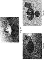
- Fig. 6a -c show an example with a test image and derived comparison values.
- Fig. 7 shows an alternative embodiment of the invention, wherein the image processing method is performed by a sensor.
- test data records 50 (FIG. Fig. 1 ), which is used to check whether a robot in kitchens can detect certain objects 102, 103, 104, 105 with the aid of color camera images.
- Objects to be recognized shown in Fig. 3 , For example, glass bottles 105, cups 104 or kitchen furnishings such as table 102 may be.
- an image processing method 80 (FIG. Fig. 2 ), which, based on camera images taken by a camera of the robot, detects the environment of that robot, in particular objects 102, 103, 104, 105 in the immediate vicinity of the robot.
- the image processing method 80 provides information about the number, location, and location of the respective items 102, 103, 104, 105, which information is used to control the robot.
- test data sets 50 are automatically generated in the form of images 5 and associated comparison values 4. It should both be possible to specify a measure 8 for the reliability of the respective image processing method 80 and to achieve this goal with the smallest possible number of test data sets 50 collected as test database 70.
- the method 90 which determines the dimension 8 by comparing the results 7 of the image processing method 80 with the comparison values 4 (expected results, result results, ground truth), is not part of the patent.
- a domain model 1 is defined for the image processing method 80 to be tested; in the present exemplary embodiment, this is a model of specific kitchen spaces and / or objects, their arrangements and lighting, with which scenes 2 of a kitchen can be created are.
- the amount of objects 102, 103, 104, 105 located in the respective scene 2 and the environment, for example in the form of an interior 101 are defined for the generation of test data sets 50.
- a number of possible internal spaces 101 are given for possible kitchens in which a kitchen robot typically moves.
- Interiors for kitchens can be varied and different, so that a variety of different possible interiors 101 comes into consideration.
- different objects 102, 103, 104, 105 can be found, which are typically found in a kitchen, for example bottles 105, glasses cups 104, fruit, kitchen cabinets, chairs and tables 102.
- the arrangement of the objects 102, 103, 104, 105 with respect to the interior 101 and the objects 102, 103, 104, 105 to each other is typically subject to certain regularities.
- objects 102, 103, 104, 105 may not float in the air, but lie on other objects or on the ground, respectively.
- the domain model specifies constraints that must be observed when creating a scene.
- the shape of the interior 101 is subject to certain restrictions.
- the domain model 1 could prescribe exclusively rectangular interiors 101 in which a table 102 is necessarily located, wherein on the table 102 certain household items such as cups 104 and bottles 105 are located.
- the model 1 it is further determined which objects 102, 103, 104, 105 can be located in the scene 2 at all.
- parameters 6 the size, appearance and optionally the number of articles 102, 103, 104, 105 can be determined.
- the described domain model 1 offers the possibility of creating 6 three-dimensional scenes 2 by specifying parameters.
- a set of specified parameters 6 concretely defines a scene 2. For example, it is determined how many objects 102, 103, 104, 105 of a certain type are contained in the scene 2, how they are aligned and where the objects 102, 103, 104, 105 are located. Further, by parameter 6, the shape of the inner space 101 can be set. Other parameters 6 serve to determine the exact position and direction of view of the observer 120. The determination of the individual parameters 6 results in that a concrete scene 2 is selected from the set of all possible scenes 2 that can be created within the framework of the domain model 1, and that a viewer 120 is arranged in the respective scene 2.
- a three-dimensional scene 2 in which a viewer 120 is arranged, is created by means of the instantiation model 10 with the domain model 1.
- rendering algorithms 40 it is determined by the Parameter 6 and the creation of the scene 2 possible to image the scene 2 and create a virtual image 5 of the scene 2.
- Domain Model 1 provides a surface model of the scene when parameter 6 is specified, as in FIG Fig. 5 represented by polygons 201.
- the entire surface of the scene 2 can thus be described, for example, by polygons 201 in the form of triangles, which abut each other in the form of a grid.
- the parameters 6 of the domain model 1 are provided in the course of the Instantutation 10 with specific values, the domain model 1 provides on the basis of these parameters 6 a concrete scene 2.
- a parameter 6 as already mentioned above, the position of the viewer 120 and the viewing direction of the observer 120 counted.
- a concrete room size and room shape of the interior 101 as well as a concrete arrangement of the objects 102, 103, 104, 105 are determined in the instantiation 10, for example an interior 101 with a base area of 2m x 3m, wherein in the middle of the round table 102 stands.
- the bottle 105 and the cup 104 On the table 102 are the bottle 105 and the cup 104 whose number, position and position are given by the parameters 6 as follows: On the north side of the table top 103 of the table 102 is a cup 104 and on the western side a glass bottle 105.
- the position of the observer 120 is opposite to the table 102 so that it completely sees the tabletop 103 of the table 102 and also the objects 104, 105 located on the tabletop 103.
- characterization points 202 are distributed on some points of the surfaces. These characterization points 202 serve as sampling points and are intended to be statistically evaluated in later method steps 20 allow the visibility of the respective object 102, 103, 104, 105 in a rendered image 5 of the respective scene 2.
- individual characterization points 202 are selected among the vertices of the triangles 201 of the surface model.
- a vertex of a triangle 201 is preferably selected as the characterization point 202 when it is on an edge of an object 102, 103, 104, 105.
- points can be chosen where the surface has a strong curvature.
- characterization points 202 may be selected at locations having significant contrast edges in the texture, eg, in the range of grains or floor patterns.
- characterization points 202 can also be arranged on homogeneous surfaces, with the characterization points 202 distributed over the surface such that the visible surface portion of the respective article 102, 103, 104, 105 is proportional to the number of visible characterization points 202. Ways of distributing characterization points 202 in this way on a surface are described, for example, in US Pat. Jiri Matousek; "Geometric Discrepancy: An Illustrated Guide (Algorithms and Combinatorics)"; Springer 2010; ISBN: 3642039413 ]. Depending on their nature, characterization points 202 are each assigned an attribute.
- the characterization points 202 located on the table 102 are each assigned an attribute "table”, the characterization points 202 on the bottle 105 are assigned the attribute "bottle”, etc.
- the following three method steps 20, 30, 40 are carried out independently of each other.
- the order of these method steps 20, 30, 40 can be set arbitrarily and it is also possible that these method steps 20, 30, 40 are executed in parallel.
- All three method steps 20, 30, 40 require as input value only the three-dimensional scene 2 created by the instant utterance 10.
- These method steps involve the creation of an image 5 of the scene 2 by a rendering method 40, the formation of a comparison value 4 (FIG. After the creation, all the results determined with these method steps, namely the image 5, the comparison value 4 and the characterization vector, are linked to one another, for example stored in a common (logical) test data set 50.
- the image 5 of the scene 2 is created by means of a rendering method 40 and kept available for further processing by the image processing method 80.
- a virtual projection of the scene 2 is generated and the behavior of a digital sensor is simulated, which depicts the respective scene 2.
- the image 5 of the scene 2 is in the form of a digital image.
- a target result 4 for the method to be checked also called ground truth value.
- This comparison value 4 provides approximately a so-called depth image, in which the distance to the object visible in this pixel is specified per pixel (pixel), or a so-called segmentation, in which all relevant objects are characterized by their own color.
- Fig. 6a -c show an example:
- a test image 5 taken with a camera is shown in FIG Fig. 6b is shown a comparison value 4, in which increasing distance is represented by increasing brightness, and in Fig. 6c a comparison value 4 is shown, in which relevant objects are identified by different colors.
- the comparison value provides the relative position of the bottle 105 or the cup 104 relative to the viewer 120 and also provides the result to be achieved for a test of the image processing method 80. Does the result value 7 determined by the image processing method 80 deviate Fig. 2 ) strongly from the respective comparison value 4 or by more than a predetermined threshold value, it can be assumed that the image processing method 80 does not function sufficiently well at least for the present test case.
- a characterization vector 3 is created for each scene 2, an example of which is described below. If the characterization vectors 3 of two scenes 2 are very similar, in particular the Euclidean distance between the characterization vectors 3 of two scenes 2 is very small, then it can be assumed that the two scenes 2 are very similar overall, so that one of the two scenes 2 is not used for testing the scene 2 Image processing method 80 is required, since both scenes cover 2 as it were the same test case.
- characterization vector 3 In order to determine the characterization vector 3 in a method step 20, based on the three-dimensional scene 2 it is determined how many characterization points 202 on an object 102, 103, 104, 105 are visible to the viewer 120 and consequently also depicted in the image 5 of the scene 2 are.
- the characterization points 202 may be assigned to a particular category. Thus, all characterization points 202 to which the attribute "table” is assigned belong to the category "table", etc. All characterization points 202 visible in image 5 of scene 2 are determined and, depending on the category, for example interior 101, table 102, cup 104, Glass bottle 105 to which these belong. For each category, the proportion of visible characterization points 202, as measured by the total number of characterization points 202 of the respective category, is determined. For example, in the present image ( Fig. 4 ) 15% of those characterization points 202, which are arranged on the interior 101 associated triangles 201 of the scene 2.
- characterization points 202 are visible, which are arranged on the table 102 associated triangles 201. Furthermore, 75% of all characterization points 202 are visible, which are arranged on the glass bottle 105 associated triangles 201, and 50% of all characterization points 202, which are arranged on the cup 104 associated triangles 201. Overall, these values give a characterization vector (0.15, 0.5, 0.75, 0.5).
- the image 5, the comparison value 4 and the characterization vector 3 are stored together in a data record 50, the data record 50 is stored in a database 70. Only the logical but not the physical connection of this data is required.
- the characterization vector 3 is compared with the already created characterization vectors 3 of preceding data sets 50, the difference being with these characterization vectors 3 - for example in the form of a Euclidean norm Difference of the characterization vectors 3 - is determined. If two characterization vectors 3 are too similar, ie if two characterization vectors 3 have a difference that falls below a predefined threshold value, then one of the two data sets 50 can be discarded. Alternatively, at the end of building the test database 70, instead of discarding test records 50, all may initially be collected and within the characterization vector space, a selection of representative test data according to the distance norms may be selected.
- the characterization vectors 3 are summarized in accumulation heaps with the aim of requiring as few heaps with half the threshold value as a radius.
- the test data, whose characterization vectors are closest to the centers of gravity of these aggregate clusters in the characterization vector space, are finally used as representative test data.
- the characterization vectors 202 have the values (0.1, 0.4, 0.7, 0.3), (0.2, 0.5, 0.4, 0.6) and (0.1, 0.2, 0.6, 0.1).
- the respective Euclidean distance of all characterization vectors 202 to the new characterization vector 202 is greater than the predetermined, selected threshold value of 0.001, so that the data record 50 is not discarded and kept available for the examination of the image processing method 80.
- the presently preferred embodiment of the invention provides a feedback step 60 which, based on the obtained characterization vector 3, modifies the parameters 6 for the creation of a new data record 50 such that a new data record 50 with an image 5, a comparison value 4 and a characterization vector 3 is created is, with the characterization vector 3 of the new data set 50 is as different as possible to the previously determined characterization vectors 3, and is ensured due to the application of the changed parameters 6 by instantiation 10 to the domain model, so that a further domain-relevant scene is created.
- the mutual distance of all previously achieved characterization vectors 3 is relatively low and is in the range between 0.1 and 0.2.
- the observer 120 is moved to another position and the viewing angle is changed so that a large area of the interior space 101 can be seen.
- the viewer 120 may look straight down, with the floor below the viewer 120 and the legs of the table 102 being imaged.
- the table 102 can be removed from the scene 2 or set to another location within the scene 2, so that the largest possible part of the interior 101 visible in the image 5 is visible.
- the feedback step 60 assigns the Euclidean distances of the characterization vectors 3 to the distances of the corresponding points in this parameter space and determines therefrom a point in the parameter space which with high probability achieves the desired (large) distance of the associated characterization vector 3 from the previous ones.
- Fig. 7 a detail of an alternative embodiment of the invention is shown in more detail. This is on the in Fig. 2 illustrated embodiment, wherein in Fig. 7 an alternative of in Fig. 2 dashed bounded area is shown.
- a sensor 91 is used in the present embodiment of the invention, to which the created digital images 5 are supplied.
- the sensor 91 which implements the image processing method or the image processing algorithm 80, is checked.
- the sensor 91 has an input part 94, which is designed in particular as a digital camera.
- the digital images 5 are displayed with a screen 51, which is assigned to the input part 94 or the camera.
- the sensor 91 continuously receives the digital images 5 produced by the screen 51 via the input part 94.
- the digital images 5 are supplied to the image processing algorithm 80 and / or method 80.
- test data in the form of digital images 5 it is also possible for the image processing algorithm 80 or method 80 to be supplied with digital images 5 by means of a test input interface 93.
- the digital images 5 are provided in a local memory as internal representations 92 of the digital images for the image processing algorithm 80 or the image processing method 80, based on the internal representation 92 for each of the digital images 5 and / or for each group of digital images 5 each an internal result 97 determined.
- the sensor 91 holds the internal result 97 as a result 98 at its output interface 96 and its output part 96, respectively.
- the result 98 and the comparison value 4 ( Fig. 2 ) are not determined according to the same criteria, so that a direct comparison between the result 98 and the comparison value 4 is not possible. This may be the case, for example, if another analog or digital coding was used in the formation of the internal result or if another calculation rule was used. In this case, it may be necessary for the result 98 of the sensor 91 to be converted by means of a conversion method 99 into a form comparable to the comparison value 4.
- the sensor 91 has a test output interface 95, which directly determines the result value 7 from the result 97, which is formed according to the same proviso as the result value.
- the result 97 is made available as a result value 7 via a test output interface 95 for further processing steps.
Landscapes
- Engineering & Computer Science (AREA)
- Physics & Mathematics (AREA)
- Theoretical Computer Science (AREA)
- General Physics & Mathematics (AREA)
- Geometry (AREA)
- Computer Graphics (AREA)
- Software Systems (AREA)
- Quality & Reliability (AREA)
- Computer Vision & Pattern Recognition (AREA)
- Computing Systems (AREA)
- Image Analysis (AREA)
- Image Processing (AREA)
- Testing, Inspecting, Measuring Of Stereoscopic Televisions And Televisions (AREA)
Claims (9)
- Procédé pour établir des jeux de données d'essai (50) pour vérifier si un algorithme et/ou un procédé de traitement d'image (80) conviennent à une certaine utilisation (domaine), le procédé de traitement d'image à étudier et/ou l'algorithme de traitement d'image à étudier (80) étant conçus pour déterminer des valeurs de résultat (7) à partir d'images numériques, dans lequela) on spécifie un modèle de domaine (1), avec lequel, à l'aide d'un certain nombre de paramètres prédéfinissables (6), il est possible de spécifier des scènes tridimensionnelles (2) typiques de l'utilisation cible,b) par spécification de paramètres (6) du modèle de domaine (1), on établit des scènes tridimensionnelles (2), auquel cas, pour chacune des scènes, la position et la direction du regard d'un observateur (120) représentent, par rapport à la scène tridimensionnelle (2) considérée, un paramètre supplémentaire (6), qui conjointement aux autres paramètres (6) est spécifié pour la scène considérée (2),c) à l'aide d'un procédé de rendu (40), à partir de la position et de l'orientation de l'observateur (120), on établit une image numérique (5) de chaque scène (2),d) à partir de la scène (2), en particulier des paramètres (6) qui caractérisent la scène (2), on détermine ou on déduit des valeurs comparatives (4),e) on stocke les valeurs de mesure (4), conjointement aux images numériques (5), en tant que jeu de données commun (50),
caractérisé en ce quef) des points contenus dans la scène tridimensionnelle (2), en particulier les sommets des éléments de surface (201), sont sélectionnés en tant que points de caractérisation (202),g) on détermine si et/ou où les points de caractérisation (202) se trouvent dans le champ de vision de l'observateur (120), et on établit un vecteur de caractérisation (3), qui contient pour chacune d'un certain nombre de catégories une valeur qui indique combien, ou quelle proportion des points de caractérisation (202) affectés à la catégorie considérée, sont visibles par l'observateur (120),h) pour chaque image (5), on stocke le vecteur de caractérisation déterminé correspondant (3) et la valeur comparative affectée (4), et en ce qu'en particulier l'image (5) est, conjointement au vecteur de caractérisation qui lui est affecté (3) et à la valeur comparative qui lui est affectée (4), stockées dans un jeu de données logique commun (50), qui ont été déterminées sur la base de la même scène (2),i) deux images (5) stockées dans les jeux de données logiques (50) sont considérées comme d'autant plus semblables qu'est plus petite la distance entre les vecteurs de caractérisation (3) qui se trouvent dans le même jeu de données logiques (50), auquel cas, pour la détermination de la similitude de deux images (5), on prédéfinit une métrique de distance pour les vecteurs de caractérisation (3), qui de préférence correspond à la distance euclidienne entre les vecteurs de caractérisation (3),j) dans un groupe de jeux de données logiques (50) ayant des vecteurs de caractérisation semblables (3), on sélectionne le vecteur de caractérisation (50) dont la distance aux autres vecteurs de caractérisation (3) est la plus faible, et on rejette les autres vecteurs de caractérisation (3),k) sur la base du vecteur de caractérisation déterminé (3), on modifie les paramètres (6) transmis au modèle de domaine (1), pour réaliser une couverture suffisante de l'espace des vecteurs de caractérisation (3), et en ce que l'établissement d'une scène (2) est de nouveau mis en oeuvre avec le jeu modifié de paramètres (6), ce processus étant répété jusqu'à ce que l'on atteigne une répartition des vecteurs de caractérisation déterminés (3) dans l'espace vectoriel des vecteurs de caractérisation (3), de telle sorte que chaque jeu supplémentaire de paramètres (6) conduise à un vecteur de caractérisation (3) qui ne soit , d'une manière correspondant à la métrique de distance sélectionnée, éloigné des vecteurs de caractérisation jusqu'à maintenant sélectionnés au point qu'il ne serait pas rejeté selon l'étape j). - Procédé selon la revendication 1, caractérisé en ce que le procédé de traitement d'image (80) et/ou l'algorithme de traitement d'image (80) sont utilisés sur les images numériques établies (5), le procédé de traitement d'image (80) et/ou l'algorithme de traitement d'image (80) déduisant des images numériques (5) un certain nombre de valeurs de résultat (7), et les valeurs de résultat (7) étant comparées aux valeurs de résultat (4) stockées conjointement à l'image numérique correspondante (5), le procédé de traitement d'image (80) et/ou l'algorithme de traitement d'image (80) étant, en cas d'écart entre la valeur de résultat (7) et la valeur comparative (4), détectés comme étant défectueux.
- Procédé selon la revendication 2 pour la vérification d'un capteur (91), caractérisé en ce que le procédé de traitement d'image (80) et/ou l'algorithme de traitement d'image (80) sont mis en oeuvre par un capteur (91),- le capteur (91) saisissant, en particulier en continu, des images numériques (5), et les mettant à la disposition du procédé de traitement d'image (80) et/ou de l'algorithme de traitement d'image (80) en tant que représentations (92) internes au capteur, et- le capteur (91) mettant à disposition, en tant que valeurs de résultat (7), des valeurs de résultat (97) du procédé de traitement d'image (80) et/ou de l'algorithme de traitement d'image (80).
- Procédé selon la revendication 3, caractérisé en ce que les images numériques (5) sont transmises à l'aide d'une interface d'entrée d'essai (93) en tant qu'entrée pour le procédé de traitement d'image (80) et/ou l'algorithme de traitement d'image (80), et/ou,
en ce que les images numériques (5), en particulier en l'absence d'interface d'entrée d'essai (93), sont par l'intermédiaire d'un écran (51), dirigé vers la partie d'entrée (94) du capteur (91), transmises en tant qu'entrée pour le procédé de traitement d'image (80) et/ou l'algorithme de traitement d'image (80). - Procédé selon la revendication 3 ou 4, caractérisé en ce que les valeurs de résultat (7) sont mises à disposition à l'aide d'une interface de sortie d'essai (95), et/ou en ce que les valeurs de résultat (7), en particulier en l'absence d'interface de sortie d'essai (95), sont à l'aide d'un procédé de conversion (99) déduites des résultats (98) du procédé de traitement d'image (80) et/ou de l'algorithme de traitement d'image (80), les résultats (97) étant tenus en réserve, par la partie sortie (96) du capteur (91), pour le procédé de conversion (99).
- Procédé selon l'une des revendications précédentes, caractérisé en ce qu'au cours de la spécification de la scène (2) est établi un modèle de surface de la scène (2), la scène (2) étant spécifiée par un certain nombre de points spat sélectionnés iaux, qui sont reliés les uns aux autres par des éléments de surface, en particulier par des polygones (201), de préférence sous forme de triangles.
- Procédé selon l'une des revendications précédentes, caractérisé en ce que- aux points de caractérisation (202) sont ajoutés des attributs qui indiquent la nature de l'objet (102, 103, 104, 105) sur lequel se trouve le point de caractérisation considéré (202).
- Procédé selon l'une des revendications précédentes, caractérisé en ce que les paramètres (6) sont choisis de telle sorte que soient couverts les configurations ou criticités ou phénomènes critiques pour l'utilisation cible, tels que par exemple des reflets ou des motifs périodiques, qui peuvent réduire la qualité de sortie des algorithmes de traitement d'image.
- Support de données sur lequel est stocké un programme informatique destiné à la mise en oeuvre d'un procédé selon l'une des revendications 1 à 9.
Applications Claiming Priority (2)
| Application Number | Priority Date | Filing Date | Title |
|---|---|---|---|
| ATA238/2012A AT512549A2 (de) | 2012-02-24 | 2012-02-24 | Verfahren zur modellbasierten Erstellung von Testdatensätzen zur Prüfung von Bildverarbeitungsalgorithmen |
| PCT/AT2013/050046 WO2013123545A2 (fr) | 2012-02-24 | 2013-02-25 | Procédé d'élaboration, basée sur un modèle, de jeux de données d'essai pour le contrôle d'algorithmes de traitement d'image |
Publications (2)
| Publication Number | Publication Date |
|---|---|
| EP2864965A2 EP2864965A2 (fr) | 2015-04-29 |
| EP2864965B1 true EP2864965B1 (fr) | 2017-11-01 |
Family
ID=47884091
Family Applications (1)
| Application Number | Title | Priority Date | Filing Date |
|---|---|---|---|
| EP13709298.7A Not-in-force EP2864965B1 (fr) | 2012-02-24 | 2013-02-25 | Procédé d'élaboration, basée sur un modèle, de jeux de données d'essai pour le contrôle d'algorithmes de traitement d'image |
Country Status (3)
| Country | Link |
|---|---|
| EP (1) | EP2864965B1 (fr) |
| AT (1) | AT512549A2 (fr) |
| WO (1) | WO2013123545A2 (fr) |
Families Citing this family (1)
| Publication number | Priority date | Publication date | Assignee | Title |
|---|---|---|---|---|
| CN115827480B (zh) * | 2022-12-20 | 2023-05-12 | 中船重工奥蓝托无锡软件技术有限公司 | 用于船舶性能预报app的自动化测试方法、装置及系统 |
-
2012
- 2012-02-24 AT ATA238/2012A patent/AT512549A2/de not_active Application Discontinuation
-
2013
- 2013-02-25 EP EP13709298.7A patent/EP2864965B1/fr not_active Not-in-force
- 2013-02-25 WO PCT/AT2013/050046 patent/WO2013123545A2/fr not_active Ceased
Non-Patent Citations (3)
| Title |
|---|
| GRIBKOV I V ET AL: "PICASSO - edge detectors evaluation system based on the comprehensive set of artificial images", PROCEEDINGS 6TH WORLD MULTICONFERENCE ON SYSTEMICS, CYBERNETICS AND INFORMATICS : JULY 14 - 18, 2002, ORLANDO, FLORIDA, USA, IIIS, ORLANDO, FL, USA, vol. 9, 1 January 2002 (2002-01-01), pages 88 - 93, XP008182232, ISBN: 978-980-07-8150-0 * |
| JEAN NONNEMAKER, HENRY S. BAIRD: "Using Synthetic Data Safely in Classifcation", 2009, XP002764186, Retrieved from the Internet <URL:http://www.lehigh.edu/~jen2/jeanspaper.pdf> [retrieved on 20161111] * |
| RANDY S ROBERTS ET AL: "Design of benchmark imagery for validating facility annotation algorithms", GEOSCIENCE AND REMOTE SENSING SYMPOSIUM (IGARSS), 2011 IEEE INTERNATIONAL, IEEE, 24 July 2011 (2011-07-24), pages 1453 - 1456, XP032061138, ISBN: 978-1-4577-1003-2, DOI: 10.1109/IGARSS.2011.6049340 * |
Also Published As
| Publication number | Publication date |
|---|---|
| AT512549A2 (de) | 2013-09-15 |
| EP2864965A2 (fr) | 2015-04-29 |
| WO2013123545A2 (fr) | 2013-08-29 |
| WO2013123545A3 (fr) | 2015-10-08 |
Similar Documents
| Publication | Publication Date | Title |
|---|---|---|
| DE69226512T2 (de) | Verfahren zur Bildverarbeitung | |
| EP2275989B1 (fr) | Caméra 3D stéréoscopique | |
| DE69020780T2 (de) | Vielfache Tiefenpuffer für Graphik und Festkörpermodellierung. | |
| DE102018102688A1 (de) | Bildverarbeitungsvorrichtung, Bildverarbeitungsprogramm und Bildverarbeitungssystem | |
| DE112012001984T5 (de) | Integrieren von Video-Metadaten in 3D-Modelle | |
| EP2528042A1 (fr) | Procédé et dispositif de remaillage de modèles de polygones en 3D | |
| DE112023000151T5 (de) | Inspektionsunterstützungssystem, inspektionsunterstützungsverfahren und inspektionsunterstützungsprogramm | |
| DE202013012443U1 (de) | Zusammenführung dreidimensionaler Modelle auf Basis des Konfidenzmaßes | |
| EP3853816A1 (fr) | Procédé mis en oeuvre par ordinateur pour la compression de données de mesure provenant d'une mesure d'un volume de mesure | |
| EP2864965A2 (fr) | Procédé d'élaboration, basée sur un modèle, de jeux de données d'essai pour le contrôle d'algorithmes de traitement d'image | |
| EP4121897A1 (fr) | Procédé et systèmes pour fournir des ensembles de données d'apprentissage marqués synthétiques et leurs applications | |
| DE102009056467A1 (de) | Verfahren zur Bestimmung von Oberflächen in Voxeldaten | |
| DE102018218611A1 (de) | Verfahren und Recheneinrichtung zum Erzeugen eines dreidimensionalen CAD-Modells | |
| EP4523055A1 (fr) | Procédé de détermination de groupes de points visibles ou non visibles à partir d'un point de vue spécifié | |
| EP1820160A1 (fr) | Procede pour realiser des dessins techniques a partir de modeles tridimensionnels comportant au moins deux elements tridimensionnels en collision | |
| DE102011075335A1 (de) | Verfahren zur rechnergestützten Lageschätzung eines Objekts | |
| DE102024117721B3 (de) | Arbeits- und Trainings-Verfahren für ein künstliches neuronales Generatornetzwerk für das Bestimmen eines Untersuchungsbereiches einer Materialoberfläche | |
| DE102005010225A1 (de) | Verfahren zum Vergleich eines realen Gegenstandes mit einem digitalen Modell | |
| DE102023102837B3 (de) | Verfahren zur Definition einer räumlichen Begrenzung eines Schutzbereichs | |
| DE102019220364A1 (de) | Kalibriereinrichtung und Verfahren zum Kalibrieren einer Vorrichtung | |
| DE102007056835A1 (de) | Bildverarbeitunsmodul zur Schätzung einer Objektposition eines Überwachungsobjekts, Verfahren zur Bestimmung einer Objektposition eines Überwachungsobjekts sowie Computerprogramm | |
| EP4660574A1 (fr) | Procédé de génération de données synthétiques d'objets, de préférence de produits | |
| DE69911780T2 (de) | Verfahren zur modellierung von gegenständen oder dreidimensionalen szenen | |
| DE102022123848A1 (de) | Bestimmung von Oberflächendaten eines Gegenstands | |
| DE102023102196A1 (de) | Computer-implementiertes verfahren und vorrichtung zum prüfen einer korrektheit eines zusammenbaus |
Legal Events
| Date | Code | Title | Description |
|---|---|---|---|
| PUAI | Public reference made under article 153(3) epc to a published international application that has entered the european phase |
Free format text: ORIGINAL CODE: 0009012 |
|
| 17P | Request for examination filed |
Effective date: 20140819 |
|
| AK | Designated contracting states |
Kind code of ref document: A2 Designated state(s): AL AT BE BG CH CY CZ DE DK EE ES FI FR GB GR HR HU IE IS IT LI LT LU LV MC MK MT NL NO PL PT RO RS SE SI SK SM TR |
|
| AX | Request for extension of the european patent |
Extension state: BA ME |
|
| DAX | Request for extension of the european patent (deleted) | ||
| R17D | Deferred search report published (corrected) |
Effective date: 20151008 |
|
| STAA | Information on the status of an ep patent application or granted ep patent |
Free format text: STATUS: EXAMINATION IS IN PROGRESS |
|
| PUAG | Search results despatched under rule 164(2) epc together with communication from examining division |
Free format text: ORIGINAL CODE: 0009017 |
|
| 17Q | First examination report despatched |
Effective date: 20161122 |
|
| B565 | Issuance of search results under rule 164(2) epc |
Effective date: 20161122 |
|
| GRAP | Despatch of communication of intention to grant a patent |
Free format text: ORIGINAL CODE: EPIDOSNIGR1 |
|
| STAA | Information on the status of an ep patent application or granted ep patent |
Free format text: STATUS: GRANT OF PATENT IS INTENDED |
|
| RIC1 | Information provided on ipc code assigned before grant |
Ipc: G06T 15/20 20110101ALI20170505BHEP Ipc: G06T 7/00 20170101ALI20170505BHEP Ipc: G06T 17/00 20060101AFI20170505BHEP |
|
| INTG | Intention to grant announced |
Effective date: 20170524 |
|
| GRAS | Grant fee paid |
Free format text: ORIGINAL CODE: EPIDOSNIGR3 |
|
| GRAA | (expected) grant |
Free format text: ORIGINAL CODE: 0009210 |
|
| STAA | Information on the status of an ep patent application or granted ep patent |
Free format text: STATUS: THE PATENT HAS BEEN GRANTED |
|
| AK | Designated contracting states |
Kind code of ref document: B1 Designated state(s): AL AT BE BG CH CY CZ DE DK EE ES FI FR GB GR HR HU IE IS IT LI LT LU LV MC MK MT NL NO PL PT RO RS SE SI SK SM TR |
|
| REG | Reference to a national code |
Ref country code: GB Ref legal event code: FG4D Free format text: NOT ENGLISH |
|
| REG | Reference to a national code |
Ref country code: CH Ref legal event code: EP Ref country code: AT Ref legal event code: REF Ref document number: 942735 Country of ref document: AT Kind code of ref document: T Effective date: 20171115 |
|
| REG | Reference to a national code |
Ref country code: IE Ref legal event code: FG4D Free format text: LANGUAGE OF EP DOCUMENT: GERMAN |
|
| REG | Reference to a national code |
Ref country code: DE Ref legal event code: R096 Ref document number: 502013008706 Country of ref document: DE |
|
| REG | Reference to a national code |
Ref country code: NL Ref legal event code: MP Effective date: 20171101 |
|
| REG | Reference to a national code |
Ref country code: LT Ref legal event code: MG4D |
|
| PG25 | Lapsed in a contracting state [announced via postgrant information from national office to epo] |
Ref country code: NO Free format text: LAPSE BECAUSE OF FAILURE TO SUBMIT A TRANSLATION OF THE DESCRIPTION OR TO PAY THE FEE WITHIN THE PRESCRIBED TIME-LIMIT Effective date: 20180201 Ref country code: ES Free format text: LAPSE BECAUSE OF FAILURE TO SUBMIT A TRANSLATION OF THE DESCRIPTION OR TO PAY THE FEE WITHIN THE PRESCRIBED TIME-LIMIT Effective date: 20171101 Ref country code: NL Free format text: LAPSE BECAUSE OF FAILURE TO SUBMIT A TRANSLATION OF THE DESCRIPTION OR TO PAY THE FEE WITHIN THE PRESCRIBED TIME-LIMIT Effective date: 20171101 Ref country code: SE Free format text: LAPSE BECAUSE OF FAILURE TO SUBMIT A TRANSLATION OF THE DESCRIPTION OR TO PAY THE FEE WITHIN THE PRESCRIBED TIME-LIMIT Effective date: 20171101 Ref country code: LT Free format text: LAPSE BECAUSE OF FAILURE TO SUBMIT A TRANSLATION OF THE DESCRIPTION OR TO PAY THE FEE WITHIN THE PRESCRIBED TIME-LIMIT Effective date: 20171101 Ref country code: FI Free format text: LAPSE BECAUSE OF FAILURE TO SUBMIT A TRANSLATION OF THE DESCRIPTION OR TO PAY THE FEE WITHIN THE PRESCRIBED TIME-LIMIT Effective date: 20171101 |
|
| PG25 | Lapsed in a contracting state [announced via postgrant information from national office to epo] |
Ref country code: GR Free format text: LAPSE BECAUSE OF FAILURE TO SUBMIT A TRANSLATION OF THE DESCRIPTION OR TO PAY THE FEE WITHIN THE PRESCRIBED TIME-LIMIT Effective date: 20180202 Ref country code: IS Free format text: LAPSE BECAUSE OF FAILURE TO SUBMIT A TRANSLATION OF THE DESCRIPTION OR TO PAY THE FEE WITHIN THE PRESCRIBED TIME-LIMIT Effective date: 20180301 Ref country code: BG Free format text: LAPSE BECAUSE OF FAILURE TO SUBMIT A TRANSLATION OF THE DESCRIPTION OR TO PAY THE FEE WITHIN THE PRESCRIBED TIME-LIMIT Effective date: 20180201 Ref country code: RS Free format text: LAPSE BECAUSE OF FAILURE TO SUBMIT A TRANSLATION OF THE DESCRIPTION OR TO PAY THE FEE WITHIN THE PRESCRIBED TIME-LIMIT Effective date: 20171101 Ref country code: HR Free format text: LAPSE BECAUSE OF FAILURE TO SUBMIT A TRANSLATION OF THE DESCRIPTION OR TO PAY THE FEE WITHIN THE PRESCRIBED TIME-LIMIT Effective date: 20171101 Ref country code: LV Free format text: LAPSE BECAUSE OF FAILURE TO SUBMIT A TRANSLATION OF THE DESCRIPTION OR TO PAY THE FEE WITHIN THE PRESCRIBED TIME-LIMIT Effective date: 20171101 |
|
| PG25 | Lapsed in a contracting state [announced via postgrant information from national office to epo] |
Ref country code: DK Free format text: LAPSE BECAUSE OF FAILURE TO SUBMIT A TRANSLATION OF THE DESCRIPTION OR TO PAY THE FEE WITHIN THE PRESCRIBED TIME-LIMIT Effective date: 20171101 Ref country code: SK Free format text: LAPSE BECAUSE OF FAILURE TO SUBMIT A TRANSLATION OF THE DESCRIPTION OR TO PAY THE FEE WITHIN THE PRESCRIBED TIME-LIMIT Effective date: 20171101 Ref country code: CZ Free format text: LAPSE BECAUSE OF FAILURE TO SUBMIT A TRANSLATION OF THE DESCRIPTION OR TO PAY THE FEE WITHIN THE PRESCRIBED TIME-LIMIT Effective date: 20171101 Ref country code: EE Free format text: LAPSE BECAUSE OF FAILURE TO SUBMIT A TRANSLATION OF THE DESCRIPTION OR TO PAY THE FEE WITHIN THE PRESCRIBED TIME-LIMIT Effective date: 20171101 Ref country code: CY Free format text: LAPSE BECAUSE OF FAILURE TO SUBMIT A TRANSLATION OF THE DESCRIPTION OR TO PAY THE FEE WITHIN THE PRESCRIBED TIME-LIMIT Effective date: 20171101 |
|
| REG | Reference to a national code |
Ref country code: DE Ref legal event code: R097 Ref document number: 502013008706 Country of ref document: DE |
|
| PG25 | Lapsed in a contracting state [announced via postgrant information from national office to epo] |
Ref country code: PL Free format text: LAPSE BECAUSE OF FAILURE TO SUBMIT A TRANSLATION OF THE DESCRIPTION OR TO PAY THE FEE WITHIN THE PRESCRIBED TIME-LIMIT Effective date: 20171101 Ref country code: RO Free format text: LAPSE BECAUSE OF FAILURE TO SUBMIT A TRANSLATION OF THE DESCRIPTION OR TO PAY THE FEE WITHIN THE PRESCRIBED TIME-LIMIT Effective date: 20171101 Ref country code: IT Free format text: LAPSE BECAUSE OF FAILURE TO SUBMIT A TRANSLATION OF THE DESCRIPTION OR TO PAY THE FEE WITHIN THE PRESCRIBED TIME-LIMIT Effective date: 20171101 Ref country code: SM Free format text: LAPSE BECAUSE OF FAILURE TO SUBMIT A TRANSLATION OF THE DESCRIPTION OR TO PAY THE FEE WITHIN THE PRESCRIBED TIME-LIMIT Effective date: 20171101 |
|
| PLBE | No opposition filed within time limit |
Free format text: ORIGINAL CODE: 0009261 |
|
| STAA | Information on the status of an ep patent application or granted ep patent |
Free format text: STATUS: NO OPPOSITION FILED WITHIN TIME LIMIT |
|
| REG | Reference to a national code |
Ref country code: CH Ref legal event code: PL |
|
| PG25 | Lapsed in a contracting state [announced via postgrant information from national office to epo] |
Ref country code: MC Free format text: LAPSE BECAUSE OF FAILURE TO SUBMIT A TRANSLATION OF THE DESCRIPTION OR TO PAY THE FEE WITHIN THE PRESCRIBED TIME-LIMIT Effective date: 20171101 Ref country code: MT Free format text: LAPSE BECAUSE OF FAILURE TO SUBMIT A TRANSLATION OF THE DESCRIPTION OR TO PAY THE FEE WITHIN THE PRESCRIBED TIME-LIMIT Effective date: 20171101 |
|
| 26N | No opposition filed |
Effective date: 20180802 |
|
| GBPC | Gb: european patent ceased through non-payment of renewal fee |
Effective date: 20180225 |
|
| REG | Reference to a national code |
Ref country code: IE Ref legal event code: MM4A |
|
| REG | Reference to a national code |
Ref country code: BE Ref legal event code: MM Effective date: 20180228 |
|
| PG25 | Lapsed in a contracting state [announced via postgrant information from national office to epo] |
Ref country code: SI Free format text: LAPSE BECAUSE OF FAILURE TO SUBMIT A TRANSLATION OF THE DESCRIPTION OR TO PAY THE FEE WITHIN THE PRESCRIBED TIME-LIMIT Effective date: 20171101 Ref country code: LI Free format text: LAPSE BECAUSE OF NON-PAYMENT OF DUE FEES Effective date: 20180228 Ref country code: CH Free format text: LAPSE BECAUSE OF NON-PAYMENT OF DUE FEES Effective date: 20180228 Ref country code: LU Free format text: LAPSE BECAUSE OF NON-PAYMENT OF DUE FEES Effective date: 20180225 |
|
| REG | Reference to a national code |
Ref country code: FR Ref legal event code: ST Effective date: 20181031 |
|
| PG25 | Lapsed in a contracting state [announced via postgrant information from national office to epo] |
Ref country code: IE Free format text: LAPSE BECAUSE OF NON-PAYMENT OF DUE FEES Effective date: 20180225 |
|
| PG25 | Lapsed in a contracting state [announced via postgrant information from national office to epo] |
Ref country code: FR Free format text: LAPSE BECAUSE OF NON-PAYMENT OF DUE FEES Effective date: 20180228 Ref country code: GB Free format text: LAPSE BECAUSE OF NON-PAYMENT OF DUE FEES Effective date: 20180225 Ref country code: BE Free format text: LAPSE BECAUSE OF NON-PAYMENT OF DUE FEES Effective date: 20180228 |
|
| PG25 | Lapsed in a contracting state [announced via postgrant information from national office to epo] |
Ref country code: TR Free format text: LAPSE BECAUSE OF FAILURE TO SUBMIT A TRANSLATION OF THE DESCRIPTION OR TO PAY THE FEE WITHIN THE PRESCRIBED TIME-LIMIT Effective date: 20171101 |
|
| PG25 | Lapsed in a contracting state [announced via postgrant information from national office to epo] |
Ref country code: PT Free format text: LAPSE BECAUSE OF FAILURE TO SUBMIT A TRANSLATION OF THE DESCRIPTION OR TO PAY THE FEE WITHIN THE PRESCRIBED TIME-LIMIT Effective date: 20171101 |
|
| PG25 | Lapsed in a contracting state [announced via postgrant information from national office to epo] |
Ref country code: MK Free format text: LAPSE BECAUSE OF NON-PAYMENT OF DUE FEES Effective date: 20171101 Ref country code: HU Free format text: LAPSE BECAUSE OF FAILURE TO SUBMIT A TRANSLATION OF THE DESCRIPTION OR TO PAY THE FEE WITHIN THE PRESCRIBED TIME-LIMIT; INVALID AB INITIO Effective date: 20130225 |
|
| PG25 | Lapsed in a contracting state [announced via postgrant information from national office to epo] |
Ref country code: AL Free format text: LAPSE BECAUSE OF FAILURE TO SUBMIT A TRANSLATION OF THE DESCRIPTION OR TO PAY THE FEE WITHIN THE PRESCRIBED TIME-LIMIT Effective date: 20171101 |
|
| PGFP | Annual fee paid to national office [announced via postgrant information from national office to epo] |
Ref country code: DE Payment date: 20220217 Year of fee payment: 10 Ref country code: AT Payment date: 20220208 Year of fee payment: 10 |
|
| REG | Reference to a national code |
Ref country code: DE Ref legal event code: R119 Ref document number: 502013008706 Country of ref document: DE |
|
| REG | Reference to a national code |
Ref country code: AT Ref legal event code: MM01 Ref document number: 942735 Country of ref document: AT Kind code of ref document: T Effective date: 20230225 |
|
| PG25 | Lapsed in a contracting state [announced via postgrant information from national office to epo] |
Ref country code: AT Free format text: LAPSE BECAUSE OF NON-PAYMENT OF DUE FEES Effective date: 20230225 |
|
| PG25 | Lapsed in a contracting state [announced via postgrant information from national office to epo] |
Ref country code: DE Free format text: LAPSE BECAUSE OF NON-PAYMENT OF DUE FEES Effective date: 20230901 |