EP2865174B1 - Module de caméra pour un véhicule et procédé pour sa fabrication - Google Patents
Module de caméra pour un véhicule et procédé pour sa fabrication Download PDFInfo
- Publication number
- EP2865174B1 EP2865174B1 EP13719106.0A EP13719106A EP2865174B1 EP 2865174 B1 EP2865174 B1 EP 2865174B1 EP 13719106 A EP13719106 A EP 13719106A EP 2865174 B1 EP2865174 B1 EP 2865174B1
- Authority
- EP
- European Patent Office
- Prior art keywords
- objective
- carrier device
- camera module
- housing portion
- image sensor
- Prior art date
- Legal status (The legal status is an assumption and is not a legal conclusion. Google has not performed a legal analysis and makes no representation as to the accuracy of the status listed.)
- Active
Links
- 238000004519 manufacturing process Methods 0.000 title claims description 8
- 230000003287 optical effect Effects 0.000 claims description 24
- 238000007789 sealing Methods 0.000 claims description 11
- 239000004020 conductor Substances 0.000 claims description 6
- 238000005516 engineering process Methods 0.000 claims description 5
- 238000006073 displacement reaction Methods 0.000 claims description 4
- 238000011156 evaluation Methods 0.000 claims description 2
- 239000004033 plastic Substances 0.000 claims description 2
- 230000000717 retained effect Effects 0.000 claims 2
- 238000004873 anchoring Methods 0.000 claims 1
- 239000000463 material Substances 0.000 claims 1
- 238000004026 adhesive bonding Methods 0.000 description 5
- 238000001514 detection method Methods 0.000 description 4
- 230000013011 mating Effects 0.000 description 4
- 239000010410 layer Substances 0.000 description 3
- 229910052751 metal Inorganic materials 0.000 description 3
- 239000002184 metal Substances 0.000 description 3
- 230000005855 radiation Effects 0.000 description 3
- 125000006850 spacer group Chemical group 0.000 description 3
- 238000003466 welding Methods 0.000 description 3
- 239000000853 adhesive Substances 0.000 description 2
- 230000001070 adhesive effect Effects 0.000 description 2
- 229910052782 aluminium Inorganic materials 0.000 description 2
- XAGFODPZIPBFFR-UHFFFAOYSA-N aluminium Chemical compound [Al] XAGFODPZIPBFFR-UHFFFAOYSA-N 0.000 description 2
- 239000000969 carrier Substances 0.000 description 2
- 230000003750 conditioning effect Effects 0.000 description 2
- 238000003384 imaging method Methods 0.000 description 2
- 238000000034 method Methods 0.000 description 2
- 238000012360 testing method Methods 0.000 description 2
- 238000012549 training Methods 0.000 description 2
- 230000000007 visual effect Effects 0.000 description 2
- 238000010521 absorption reaction Methods 0.000 description 1
- 239000012790 adhesive layer Substances 0.000 description 1
- 230000015572 biosynthetic process Effects 0.000 description 1
- 150000001875 compounds Chemical class 0.000 description 1
- 238000010276 construction Methods 0.000 description 1
- 238000013461 design Methods 0.000 description 1
- 238000004512 die casting Methods 0.000 description 1
- 238000003754 machining Methods 0.000 description 1
- 230000005226 mechanical processes and functions Effects 0.000 description 1
- 239000002991 molded plastic Substances 0.000 description 1
- 238000012544 monitoring process Methods 0.000 description 1
- 238000012805 post-processing Methods 0.000 description 1
- 238000012545 processing Methods 0.000 description 1
- 239000002356 single layer Substances 0.000 description 1
- 239000000758 substrate Substances 0.000 description 1
Images
Classifications
-
- B—PERFORMING OPERATIONS; TRANSPORTING
- B60—VEHICLES IN GENERAL
- B60R—VEHICLES, VEHICLE FITTINGS, OR VEHICLE PARTS, NOT OTHERWISE PROVIDED FOR
- B60R11/00—Arrangements for holding or mounting articles, not otherwise provided for
- B60R11/04—Mounting of cameras operative during drive; Arrangement of controls thereof relative to the vehicle
-
- H—ELECTRICITY
- H04—ELECTRIC COMMUNICATION TECHNIQUE
- H04N—PICTORIAL COMMUNICATION, e.g. TELEVISION
- H04N23/00—Cameras or camera modules comprising electronic image sensors; Control thereof
- H04N23/50—Constructional details
- H04N23/51—Housings
-
- H—ELECTRICITY
- H04—ELECTRIC COMMUNICATION TECHNIQUE
- H04N—PICTORIAL COMMUNICATION, e.g. TELEVISION
- H04N23/00—Cameras or camera modules comprising electronic image sensors; Control thereof
- H04N23/50—Constructional details
- H04N23/54—Mounting of pick-up tubes, electronic image sensors, deviation or focusing coils
-
- H—ELECTRICITY
- H04—ELECTRIC COMMUNICATION TECHNIQUE
- H04N—PICTORIAL COMMUNICATION, e.g. TELEVISION
- H04N23/00—Cameras or camera modules comprising electronic image sensors; Control thereof
- H04N23/57—Mechanical or electrical details of cameras or camera modules specially adapted for being embedded in other devices
-
- B—PERFORMING OPERATIONS; TRANSPORTING
- B60—VEHICLES IN GENERAL
- B60R—VEHICLES, VEHICLE FITTINGS, OR VEHICLE PARTS, NOT OTHERWISE PROVIDED FOR
- B60R11/00—Arrangements for holding or mounting articles, not otherwise provided for
- B60R2011/0001—Arrangements for holding or mounting articles, not otherwise provided for characterised by position
- B60R2011/0003—Arrangements for holding or mounting articles, not otherwise provided for characterised by position inside the vehicle
- B60R2011/0026—Windows, e.g. windscreen
-
- Y—GENERAL TAGGING OF NEW TECHNOLOGICAL DEVELOPMENTS; GENERAL TAGGING OF CROSS-SECTIONAL TECHNOLOGIES SPANNING OVER SEVERAL SECTIONS OF THE IPC; TECHNICAL SUBJECTS COVERED BY FORMER USPC CROSS-REFERENCE ART COLLECTIONS [XRACs] AND DIGESTS
- Y10—TECHNICAL SUBJECTS COVERED BY FORMER USPC
- Y10T—TECHNICAL SUBJECTS COVERED BY FORMER US CLASSIFICATION
- Y10T29/00—Metal working
- Y10T29/49—Method of mechanical manufacture
- Y10T29/49826—Assembling or joining
Definitions
- Camera modules for vehicles generally include a lens having a lens frame and at least one lens, an image sensor, and a support on which the image sensor is mounted and contacted.
- the support device is z. B. formed as a printed circuit board.
- the lens is recorded longitudinally adjustable in a lens mount (lens holder, lens holder) to allow an adjustment.
- the lens mount is generally attached to the support means.
- the adjustment is done by z. B. a test pattern is detected in a relevant subject matter and the image signals of the image sensor are evaluated to determine a longitudinal position of the lens with the best possible contrast and adjust, so that the image sensor is in the image plane. Subsequently, the lens is fixed to the lens mount. Then, the assembly of support means with image sensor and fixed to the carrier device lens, which is generally referred to as an imager module, installed in a camera body, which serves to protect against external influences and for mounting in the vehicle.
- an imager module installed in a camera body, which serves to protect against external influences and for mounting in the vehicle.
- the electrical connection of the image sensor should be as free of force as possible in order to minimize the influence on the positional stability in the image plane.
- the assembly formed by the image sensor and the objective defines the optical axis and should preferably be mountable in the camera housing in such a way that the central visual axis, ie the axis of symmetry of the detection range or opening angle, can be precisely defined.
- the DE 10 2009 027 514 A1 shows such a camera module, in which the lens is fixed to the lens mount (lens holder) by a curing under UV radiation adhesive.
- the US Pat. No. 6,507,700 B1 shows the construction of a waterproof camera, which includes a lens, a housing and an image sensor.
- the WO 2007/107392 A1 shows a camera module in which the image sensor from the back of the optics can be attached and fixed.
- the DE 10 2010 003955 A1 shows a multi-part camera housing for a vehicle, in which an image sensor and an optical holder with a lens, and a circuit substrate are accommodated for receiving a plug connection.
- the WO 2006/087284 A1 discloses a method for optical adjustment of a Schmgebeoptik with at least one optical sensor medium, wherein a plastically deformable Justageelement is plastically deformed by the action of a force.
- the US 2005/035421 A1 shows a compact imaging module, wherein the imaging sensor is mounted on an electrical support layer.
- the DE 10 2005 000655 A1 shows an image detection device with a board arranged on a circuit arrangement and an image sensor, wherein on the image sensor supporting board at least one shielding layer is arranged and this shielding layer is electrically connected to the housing leads of the board and to the housing.
- Disadvantages are generally the complex production of a plurality of components with corresponding tolerances and the problem of fixing the visual axis with respect to the camera body.
- the lens is connected to the camera body. With this connection, the lens is supported by the camera body.
- the carrier device according to different embodiments, be attached to the lens and / or on the first housing part and is thereby held.
- the lens is thus not held and / or carried by the carrier device, which in turn is then carried by the camera body, but the camera housing, in particular a first housing part, already serves to receive and hold the objective.
- corresponding fitting surfaces on the lens, z. B. the outside of the lens frame, and the first housing part of the camera body.
- the compound can be directly, i. be formed by direct investment of fitting surfaces, or indirectly by interposed intermediate means, such as spacers.
- the carrier device is mounted with mounted image sensor.
- the lens is thus first placed in the first housing part, followed by the adjustment and / or focusing, in which the carrier device is mounted together with mounted image sensor relative to the lens, in particular by longitudinal adjustment along an axis of symmetry of the lens , which thus forms the optical axis.
- the carrier device is mounted together with mounted image sensor relative to the lens, in particular by longitudinal adjustment along an axis of symmetry of the lens , which thus forms the optical axis.
- the first housing part can be used in particular as a die-cast part made of metal, for. As aluminum, to allow high dimensional stability, stability and accuracy of positioning of the attached lens.
- the first housing part can preferably be post-processed in its contact surface for receiving the objective.
- MID components metallic conductor tracks for electrical connections are located directly on z.
- an additional lens holder (lens holder), which is to be attached to the support device, omitted, so that also the number of parts and the tolerances occurring can be reduced.
- the training allows the Support device in MID technology suitable shapes for guiding and positioning on the lens and for sealing and / or for attachment to the first housing part.
- the support means can be fixed in the fixation after focusing instead of the lens on the lens housing rigidly connected to the first housing part, which can be done differently according to different embodiments by the free designability of the first housing part and the support means in many areas, to tightness, high stability and process technology easy attachment by z. B. to ensure bonding.
- the three-dimensional, one-piece (MID) design of the carrier device enables particular advantages in combination with the direct connection of the objective to the first housing part.
- the second housing part can, for. B. also be formed as a metal die-cast part.
- the optical properties including adjustment, positioning of the image sensor and alignment of the viewing direction of the imager module in the camera housing, preferably also the inclusion of a main circuit carrier for the further active and passive components of the camera module and possibly also the attachment of a camera holder, only the first housing part is relevant and the second housing part thus only serves to complete the camera housing and the seal.
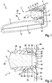
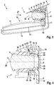
- the camera module 1 of Fig. 1, 2 and 3 is in each case behind a vehicle window 2, in particular windscreen or rear window, mounted a (not shown in detail) vehicle 6. Radiation 27, in particular light in the visible range or also in the IR range, is received by the camera module 1. The radiation 27 can in particular pass through the vehicle window 2, ie come from the outside, and / or from the vehicle interior to the interior monitoring; Furthermore, in a sensor of the disc outer surface and z. B. light is coupled into the vehicle window 2 and subsequently sensed by the camera module 1.
- the camera module 1 has: a lens 3 having a lens frame 5 and at least one lens 4 received in the lens frame 5, an image sensor 8, a carrier device 9 and a camera body 10. Furthermore, z. B. a camera holder for attachment of the camera body 10 may be provided on the vehicle window 2.
- the image sensor 8 for detecting and converting optical signals into electrical signals S1 may in particular be an imager chip.
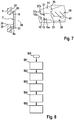
- the image sensor 8 and the objective 3 define an optical axis 28 Fig. 7 be removed can, the image sensor 8, a photosensitive sensor surface 7 and signal lines 30 and Mixier vom 31, which are contacted via contacting means 29, in particular Stud bumps 29, with conductor tracks 32 of the support means 9.
- the image sensor 8 is preferably mounted in flip-chip technology, so that both the photosensitive sensor surface 7 and the signal lines 30 and contact surfaces 31 are arranged on its front side 8a (upper side).
- a recess 35 is provided for the passage of light.
- the carrier device 9 is designed as a MID (Molded Interconnect Device) carrier device 9 made of a plastic and contoured three-dimensionally. In addition to the image sensor 8, it can also accommodate a part of the signal conditioning circuitry of the image signal S1, i. it may be additionally attached to the carrier device 9 passive components 36 for signal conditioning, one of which is indicated.
- the conductor tracks 30 are mounted on a rear side 9b of the carrier device 9 and preferably form a single-layer wiring plane; As shown, they can extend to a side edge of the carrier device 9 for better contacting.
- the front side 9a of the support device 9 is more contoured.
- the carrier device 9 has, on its front side 9a, lens-receiving means 18, 19 for receiving and / or sealing the objective 3, which are designed differently according to the embodiments and respectively a displacement of the objective 3 in the direction of the optical axis 28 for focusing the camera module 1 allow, so that positioning of the image sensor 8 in the respective image plane upon detection z.
- the lens receiving means 18, 19 are formed differently according to the embodiments; In this case, in each case an inner sealing ring 19 is provided in these embodiments, which engages in a groove 20 of the lens frame 5.
- the camera body 10 is composed of a first housing part 11 for receiving the lens 3 and the support means 9 and a second housing part 12 for closing the first housing part 11.
- the housing parts 11 and 12 are preferably each made as metal die-cast parts and in particular as aluminum die-cast parts.
- the first housing part 11 is the upper housing part and is closed by the lower second housing part 12 to the rear and bottom.
- the camera body 10 may have further components; However, the embodiments shown allow complete absorption of the components at low production costs, since the housing parts 11, 12 have no Hintergreifept.
- the first housing part 11 has a first housing-fitting surface 37, with which it bears against a first lens-fitting surface 16 (directly or indirectly).
- a first lens-fitting surface 16 directly or indirectly.
- the first lens-fitting surface 16 over partial surfaces 16a and 16b, wherein the partial surface 16a is a cylindrical outer surface of the lens frame 5 and the partial surface 16b is formed on the back of a shoulder 38 and as a stop when inserting the lens 3 in the housing part. 3 serves.
- the first housing-fitting surface 37 of the first housing part 11 is formed by the partial surfaces 37a and 37b, of which the partial surface 37a is cylindrical and the partial surface 37b z. B. perpendicular to this and serves to rest on the partial surface 16b.
- the first housing-fitting surface 37 is precisely formed for accurate recording, preferably by machine post-processing of the housing part 11 produced by die-casting, in particular by machining. It thus serves as the first fitting section for the fit of the objective 3 in the first housing part 11.
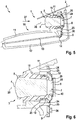
- FIGS. 1 to 6 differ in particular with respect to the attachment of the MID carrier device 9 and the formation of the mating surfaces.
- the MID carrier 9 is attached only to the lens 3 or its lens frame 5.
- the MID carrier device 9 in addition to the engaging in the groove 20 inner sealing ring 19 on an outer support ring 18 which rests with a fitting surface 41 on a cylindrical second lens-fitting surface 39, so that the longitudinal displacement along the optical axis 38 for focusing is possible.
- the second lens-fitting surface 39 thus serves as a second fitting portion of the lens 3 for the fit of the lens 3 to the support means 9.
- the two lens-fitting surfaces 16 and 39 are thus cylindrical and thus precisely formed and lie in the direction of the optical axis 38 in a row.
- the inner sealing ring 19 can be without a supporting function and only serve for guiding and / or sealing.
- the carrier device 9 is connected via its interconnects 32 and a data connection 14, z.
- a main circuit carrier for. B. a printed circuit board 13, which ensures the full functionality of the camera module 1 and thus active and passive components 42 for receiving and processing the image signal S1, preferably also for contacting, in the vehicle 6 having.
- a step St1 For mounting and / or production of the camera module 1 of Fig. 1, 2 is according to Fig. 8 after a start in step St0, in a step St1, firstly the objective 3 formed from lens mount 5 and lens 4 is moved from the front side, ie, into Fig. 1, 2 from the left, placed in the first housing part 11, so that the surfaces 16 and 37 come to rest, that is to stop the shoulder 38 of the lens frame 5 on the first housing part 11.
- an adhesive can be used, or z , As a H Jardinverstemmung or welding done.
- a second step St2 the support means 9 with already mounted and contacted image sensor 8 from the right, i. the back, attached to the lens frame 5, so that the inner support ring 19 engages in the groove 20 and the outer support ring 18 abuts the lens-fitting surface 39.
- a longitudinal displacement of the carrier device 9 takes place along the optical axis 28 with detection of a test pattern and evaluation of the image signals S1 until an adjustment is achieved by reaching an optimum image.
- step St3 the support means 9 is then fixed to the lens frame 5, e.g. by gluing the inner support ring 19 in the groove 20 and / or by passing or welding the mating surface 41 of the outer support ring 18 to the second lens mating surface 39.
- step St4 the carrier device 9 is contacted via the data line 14 with the circuit board 13, wherein the circuit board 13 z. B. is already fixed to the first housing part 11 by gluing.
- this contacting of the step St4 can also have been effected beforehand, so that the circuit board 13 with its components is already used for evaluating the image signals S1.
- step St5 the camera body 10 is closed by attaching the lower second housing part 12 to the first housing part 11, e.g. As by caulking, gluing, welding or other industrially applicable types of fastening.
- the lens 3 has only the first lens fitting surface 16 as a fitting portion, which ensures the seat of the lens 3 in the first housing part 11, but not the second lens-fitting surface 41 of Fig. 1, 2 ,
- step St3 takes place in the second embodiment on the first housing part 11, here z. B. via an end-side, annular contact surface (mating surface) 22 of the outer support ring 18 and a corresponding annular second housing fitting surface 26, z. B. by gluing, in particular with an adhesive layer 23, the z. B. is introduced from the outside and fills a gap between the surfaces 22, 26.
- the second embodiment offers additional degrees of freedom as a tolerance compensation for the positioning of the support device 9, with which certain deviations of the lens 3, in particular Jardinebenenverkoppept, or the support means 9, in particular a lateral offset of the image sensor 8, are compensated for an active adjustment to a certain extent can.
- the groove 20 for the inner sealing ring 19 can preferably be designed to be larger than in Fig. 1 to support this tolerance compensation.
- the fixing of the support means 9 carrying the image sensor 8 is likewise effected on the first housing part 11;
- the carrier device 9 as in Fig. 6 shown one or more receptacles 24 (recesses, through holes), in which a corresponding number of preferably parallel to the optical axis 28 extending anchor elements 25 of the first housing part 11 engages. This connection can in turn be made by gluing.
- At least three receptacles 24 in the support means 9 and anchor members 25 of the first housing part 11 are provided, for. B. in a symmetrical arrangement, in particular 120 °. Due to the multiple point connections a high mechanical stability is achieved.
Landscapes
- Engineering & Computer Science (AREA)
- Multimedia (AREA)
- Signal Processing (AREA)
- Mechanical Engineering (AREA)
- Lens Barrels (AREA)
- Studio Devices (AREA)
Claims (11)
- Module de caméra (1), dans lequel le module de caméra (1) comporte au moins :un objectif (3) avec une monture de lentille (5) et au moins une lentille (4), un capteur d'image (8) pour saisir et convertir des signaux optiques en signaux d'image électriques (S1), un dispositif de support (9),sur lequel le capteur d'image (8) est monté et mis en contact, etun boîtier de caméra (10) pour accueillir l'objectif (3) et le dispositif de support (9), dans lequel le boîtier de caméra (10) comporte une première partie de boîtier (11) et l'objectif (3) est raccordé à la première partie de boîtier (11) et porté par la première partie de boîtier (11),caractérisé en ce que- le dispositif de support (9) est fixé et maintenu sur l'objectif (3) et en ce que l'objectif (3) comporte une première surface d'adaptation d'objectif (37) afin de le solidariser à la première partie de boîtier (11) et une deuxième surface d'adaptation d'objectif (29) cylindrique décalée de celle-ci le long de l'axe optique (28) pour solidariser le dispositif de support (9), ou- en ce que le dispositif de support (9) est fixé et maintenu sur la première partie de boîtier (11) et- en ce que le dispositif de support (9) comporte un anneau porteur (18) essentiellement parallèle à l'axe optique (28), lequel est fixé frontalement sur la première partie de boîtier (11) ; ou- en ce que le dispositif de support (9) comporte des emplacements (24), à l'intérieur desquels des éléments d'ancrage (25) de la première partie de boîtier (11) sont amarrés.
- Module de caméra (1) selon la revendication 1, caractérisé en ce qu'une première surface d'adaptation de boîtier (37) est réalisée sur la première partie de boîtier (11), et
l'objectif (3) comporte une première surface d'adaptation d'objectif (16), dans lequel la première surface d'adaptation de boîtier (37) et la première surface d'adaptation d'objectif (16) sont raccordées l'une à l'autre directement ou par le biais d'un intercalaire. - Module de caméra (1) selon la revendication 2, caractérisé en ce que la première surface d'adaptation de boîtier (37) et la première surface d'adaptation d'objectif (16) sont réalisées au moins en partie de manière cylindrique, et
une butée (38) est réalisée sur l'objectif et/ou sur la première partie de boîtier (11) pour fixer la position de l'objectif (3) dans la première partie de boîtier (11) . - Module de caméra (1) selon la revendication 1, caractérisé en ce que le dispositif de support (9) est réalisé comme support de circuit à contour tridimensionnel, lequel comporte au moins une bande conductrice (32) créant un contact avec le capteur d'image (8) et des moyens d'accueil d'objectif (18, 19) pour accueillir et/ou joindre l'objectif (3) de façon étanche.
- Module de caméra (1) selon la revendication 4, caractérisé en ce que les moyens d'accueil d'objectif (18, 19) sont réalisés sur une face avant (9a) du dispositif de support (9) faisant face à l'objectif (3) et l'au moins une bande conductrice (32) est réalisée comme plan de câblage sur la face arrière (9b) du dispositif de support (9).
- Module de caméra (1) selon la revendication 4 ou 5, caractérisé en ce que le dispositif de support (9) comporte dans la zone de l'axe optique (28) une échancrure (35) et le capteur d'image (8) est monté sur la face arrière du dispositif de support (9) de telle façon que sa surface de capteur photosensible (7) est orientée vers l'objectif (3) au travers de l'échancrure (35), de préférence selon la technique des puces à protubérances (Flip-Chip).
- Module de caméra (1) selon la revendication 6, caractérisé en ce que les fils de signaux (8), les surfaces de contact (31) et la surface de capteur photosensible (7) du capteur d'image (8) sont réalisées sur la face avant (8a) du capteur d'image (8), dans lequel les surfaces de contact (31) entre en contact avec l'au moins une bande conductrice (32) du dispositif de support (9) par le biais de moyens de contact.
- Module de caméra (1) selon l'une des revendications 4 à 7, caractérisé en ce que le dispositif de support (9) est réalisé comme support de circuit d'une pièce en plastique, en particulier comme support de circuit (9) moulé par injection, et les moyens d'accueil d'objectif (18, 19) sont réalisés comme profilages saillant dans la direction des axes optiques (28).
- Module de caméra (1) selon la revendication 8, caractérisé en ce que les moyens d'accueil d'objectif (18, 19) comportent un moyen d'étanchéité (18), lequel entre en prise dans une rainure (20) ou une dépression de l'objectif (3) et peut coulisser longitudinalement dans la rainure (20) ou la dépression en direction de l'axe optique (28) pour une mise au point du capteur d'image (8) relativement à l'objectif (3).
- Module de caméra (1) selon l'une des revendications 1 à 9, caractérisé en ce que le dispositif de support (9) entre en contact avec un premier support de circuit principal (13) accueilli sur la première partie de boîtier (11).
- Procédé de fabrication d'un module de caméra (1) selon l'une des revendications 1 à 10, avec au moins les étapes suivantes :solidarisation d'un objectif (3) à une première partie de boîtier (11) (St1),application sur l'objectif (3) d'un dispositif de support (9), sur lequel le capteur d'image (8) est monté et mis en contact, et ajustement par coulissement longitudinal du dispositif de support (9) le long d'un axe optique (28) de l'objectif (3) en exploitant les signaux d'image (S1) du capteur d'image (8) (St2),fixation du dispositif de support (9) sur l'objectif (3) et/ou la première partie de boîtier (11) (St3), etfermeture de la première partie de boîtier (11) par au moins une deuxième partie de boîtier (12) pour réaliser un boîtier de caméra (10), à l'intérieur duquel l'objectif (3) et le dispositif de support (9) sont accueillis (St5).
Applications Claiming Priority (2)
| Application Number | Priority Date | Filing Date | Title |
|---|---|---|---|
| DE102012210818.1A DE102012210818A1 (de) | 2012-06-26 | 2012-06-26 | Kameramodul für ein Fahrzeug und Verfahren zu dessen Herstellung |
| PCT/EP2013/058842 WO2014000914A1 (fr) | 2012-06-26 | 2013-04-29 | Module de caméra pour un véhicule et procédé pour sa fabrication |
Publications (2)
| Publication Number | Publication Date |
|---|---|
| EP2865174A1 EP2865174A1 (fr) | 2015-04-29 |
| EP2865174B1 true EP2865174B1 (fr) | 2019-08-28 |
Family
ID=48190981
Family Applications (1)
| Application Number | Title | Priority Date | Filing Date |
|---|---|---|---|
| EP13719106.0A Active EP2865174B1 (fr) | 2012-06-26 | 2013-04-29 | Module de caméra pour un véhicule et procédé pour sa fabrication |
Country Status (6)
| Country | Link |
|---|---|
| US (1) | US9832356B2 (fr) |
| EP (1) | EP2865174B1 (fr) |
| JP (1) | JP6086978B2 (fr) |
| CN (1) | CN104412572B (fr) |
| DE (1) | DE102012210818A1 (fr) |
| WO (1) | WO2014000914A1 (fr) |
Families Citing this family (21)
| Publication number | Priority date | Publication date | Assignee | Title |
|---|---|---|---|---|
| JP6413754B2 (ja) * | 2014-03-10 | 2018-10-31 | 株式会社デンソー | 撮像装置および撮像装置を備えた車載装置 |
| DE102014205708B4 (de) * | 2014-03-27 | 2024-08-01 | Continental Autonomous Mobility Germany GmbH | Kamerasystem eines Fahrassistenzsystems sowie Verfahren zur Herstellung eines solchen |
| DE102014208487B4 (de) * | 2014-05-07 | 2025-01-02 | Continental Autonomous Mobility Germany GmbH | Kamera eines Assistenzsystems eines Kraftfahrzeugs sowie Verfahren zur Herstellung eines derartigen Assistenzsystems |
| DE102014220561A1 (de) * | 2014-10-10 | 2016-04-14 | Conti Temic Microelectronic Gmbh | Umfeldkamera und Verfahren zur Herstellung einer Umfeldkamera |
| KR101724299B1 (ko) | 2015-02-04 | 2017-04-07 | 엘지전자 주식회사 | 트리플 카메라 |
| CN106476716B (zh) * | 2015-08-27 | 2019-04-19 | 日本电产艾莱希斯株式会社 | 车辆的制造方法 |
| US10230875B2 (en) * | 2016-04-14 | 2019-03-12 | Magna Electronics Inc. | Camera for vehicle vision system |
| DE102016102904A1 (de) * | 2016-02-19 | 2017-08-24 | Valeo Schalter Und Sensoren Gmbh | Fahrzeugkamerasystem, Objektivmodul eines Fahrzeugkamerasystems und Verfahren zur Herstellung eines Fahrzeugkamerasystems |
| US11150448B2 (en) | 2016-11-06 | 2021-10-19 | Denso Corporation | Vehicle windshield mounted camera module |
| EP3379331B1 (fr) * | 2017-03-20 | 2020-10-14 | Veoneer Sweden AB | Système d'imagerie pour véhicule à moteur |
| DE102017007176A1 (de) * | 2017-08-01 | 2019-02-07 | Fagus-Grecon Greten Gmbh & Co. Kg | Optische Detektorvorrichtung |
| DE102018202205A1 (de) * | 2018-02-13 | 2019-08-14 | Conti Temic Microelectronic Gmbh | Telekamera für ein Fahrzeug sowie Befestigung einer Telekamera am Fahrzeug |
| US10179550B1 (en) * | 2018-02-15 | 2019-01-15 | GM Global Technology Operations LLC | Flush-mount sensor lens assembly |
| CN210062890U (zh) * | 2018-04-20 | 2020-02-14 | 株式会社小糸制作所 | 传感器模块 |
| CN109719739A (zh) * | 2018-12-28 | 2019-05-07 | 深圳市奇信智能科技有限公司 | 易于装配麦克风盘的机器人 |
| CN110198403A (zh) * | 2019-06-18 | 2019-09-03 | 广州驰享汽车用品有限公司 | 一种倒车摄像头 |
| EP3879807B1 (fr) * | 2020-03-11 | 2023-12-20 | Ficosa Adas, S.L.U. | Ensemble caméra pour véhicules à moteur et son procédé d'assemblage |
| DE102021118728A1 (de) | 2021-07-20 | 2023-01-26 | Valeo Schalter Und Sensoren Gmbh | Kameragehäuseanordnung für eine Kraftfahrzeugkamera und Verfahren zum Zusammenbauen einer Kamera |
| DE102022104773A1 (de) | 2022-03-01 | 2023-09-07 | Valeo Schalter Und Sensoren Gmbh | Kameravorrichtung für ein fahrzeug, fahrzeug und verfahren zurherstellung einer kameravorrichtung |
| JP2025034533A (ja) * | 2023-08-31 | 2025-03-13 | マクセル株式会社 | レンズユニット、カメラモジュール、撮像システムおよび移動体 |
| DE102023131640A1 (de) | 2023-11-14 | 2025-05-15 | Bayerische Motoren Werke Aktiengesellschaft | Personenkraftwagen mit einer an einer Heckscheibe angebrachten Rückfahrkamera |
Family Cites Families (17)
| Publication number | Priority date | Publication date | Assignee | Title |
|---|---|---|---|---|
| JP2002090603A (ja) | 2000-07-10 | 2002-03-27 | Matsushita Electric Ind Co Ltd | 防水カメラ |
| JP2005006769A (ja) | 2003-06-17 | 2005-01-13 | Olympus Corp | カプセル内視鏡 |
| JP4441211B2 (ja) * | 2003-08-13 | 2010-03-31 | シチズン電子株式会社 | 小型撮像モジュール |
| DE102005000655A1 (de) * | 2005-01-04 | 2006-07-13 | Robert Bosch Gmbh | Bilderfassungseinrichtung |
| DE102005006755A1 (de) * | 2005-02-15 | 2006-08-17 | Robert Bosch Gmbh | Verfahren zur optischen Justage einer Kamera |
| JP4233536B2 (ja) * | 2005-03-31 | 2009-03-04 | シャープ株式会社 | 光学装置用モジュール |
| JP4652149B2 (ja) * | 2005-06-27 | 2011-03-16 | 京セラ株式会社 | カメラモジュール |
| JP2007225991A (ja) | 2006-02-24 | 2007-09-06 | Auto Network Gijutsu Kenkyusho:Kk | 車載カメラのレンズ取付構造 |
| DE102006013164A1 (de) * | 2006-03-22 | 2007-09-27 | Robert Bosch Gmbh | Verfahren zur Montage eines Kameramoduls und Kameramodul |
| JP2008046169A (ja) | 2006-08-10 | 2008-02-28 | Nidec Nissin Corp | レンズユニット |
| KR100896645B1 (ko) * | 2007-10-29 | 2009-05-08 | 삼성전기주식회사 | 카메라 모듈 패키지 |
| JP5333250B2 (ja) * | 2009-01-23 | 2013-11-06 | 株式会社ニコン | 撮像装置 |
| DE102009027514B4 (de) | 2009-07-08 | 2018-06-28 | Robert Bosch Gmbh | Kameramodul und Verfahren zu dessen Herstellung |
| KR20110028767A (ko) * | 2009-09-14 | 2011-03-22 | 삼성전기주식회사 | 차량용 카메라 모듈 |
| JP5771901B2 (ja) | 2010-03-29 | 2015-09-02 | 株式会社リコー | 撮像装置 |
| DE102010003955A1 (de) * | 2010-04-14 | 2011-10-20 | Robert Bosch Gmbh | Kamera für ein Fahrzeug |
| DE102012222905A1 (de) * | 2012-12-12 | 2014-06-12 | Robert Bosch Gmbh | Kameraanordnung und Verfahren zu deren Herstellung |
-
2012
- 2012-06-26 DE DE102012210818.1A patent/DE102012210818A1/de not_active Ceased
-
2013
- 2013-04-29 EP EP13719106.0A patent/EP2865174B1/fr active Active
- 2013-04-29 CN CN201380034517.6A patent/CN104412572B/zh not_active Expired - Fee Related
- 2013-04-29 JP JP2015517644A patent/JP6086978B2/ja not_active Expired - Fee Related
- 2013-04-29 WO PCT/EP2013/058842 patent/WO2014000914A1/fr not_active Ceased
- 2013-04-29 US US14/410,682 patent/US9832356B2/en not_active Expired - Fee Related
Non-Patent Citations (1)
| Title |
|---|
| None * |
Also Published As
| Publication number | Publication date |
|---|---|
| US20150207967A1 (en) | 2015-07-23 |
| DE102012210818A1 (de) | 2014-01-02 |
| JP2015524084A (ja) | 2015-08-20 |
| WO2014000914A1 (fr) | 2014-01-03 |
| US9832356B2 (en) | 2017-11-28 |
| JP6086978B2 (ja) | 2017-03-01 |
| EP2865174A1 (fr) | 2015-04-29 |
| CN104412572A (zh) | 2015-03-11 |
| CN104412572B (zh) | 2019-08-16 |
Similar Documents
| Publication | Publication Date | Title |
|---|---|---|
| EP2865174B1 (fr) | Module de caméra pour un véhicule et procédé pour sa fabrication | |
| WO2014090466A1 (fr) | Système de caméra et procédé pour le fabriquer | |
| DE102017203364B4 (de) | Kameravorrichtung und kameramodul | |
| DE102010003666A1 (de) | Kamera für ein Fahrzeug | |
| WO2007107392A1 (fr) | Procede pour le montage d'un module de camera et module de camera | |
| DE102008047277A1 (de) | Optische Einrichtung, insbesondere Bilderfassungskamera zur Anwendung in einem Kraftfahrzeug | |
| WO2013160107A2 (fr) | Module de caméra destiné en particulier à un véhicule | |
| WO2008046565A1 (fr) | Système de caméra pour la surveillance d'une zone d'espace | |
| WO2015197343A1 (fr) | Caméra, pouvant être utilisé en particulier dans un véhicule, et procédé de fabrication d'une telle caméra | |
| DE102014211879A1 (de) | Verfahren zum Herstellen einer Kamera und Kamera für ein Fahrzeug | |
| DE102014208487B4 (de) | Kamera eines Assistenzsystems eines Kraftfahrzeugs sowie Verfahren zur Herstellung eines derartigen Assistenzsystems | |
| WO2011131164A1 (fr) | Dispositif optique et procédé de positionnement d'un élément optique au-dessus d'un élément capteur d'images | |
| DE102018202205A1 (de) | Telekamera für ein Fahrzeug sowie Befestigung einer Telekamera am Fahrzeug | |
| DE102011110167B4 (de) | Bildaufnahmevorrichtung mit einem Abstandskompensationselement sowie Kamera und Fahrzeug mit einer Bildaufnahmevorrichtung | |
| DE102004044503B4 (de) | Verfahren zur Montage des Objektivs einer Kamera | |
| WO2013056700A1 (fr) | Dispositif optique pour un véhicule | |
| WO2014146863A1 (fr) | Système de caméra, en particulier pour un véhicule, et procédé pour le fabriquer | |
| DE102014224416A1 (de) | Anordnung für ein optisches Sensorsystem für ein Fahrzeug sowie Verfahren zur deren Herstellung | |
| EP2560038B1 (fr) | Monture pour élément optique et procédé de montage | |
| EP2530351A1 (fr) | Support optique | |
| DE102018207297A1 (de) | LIDAR Messsystem und Verfahren zur Montage eines LIDAR Messsystems | |
| DE102010010405A1 (de) | Optische Vorrichtung und Verfahren zur Ausrichtung und Fixierung der optischen Vorrichtung | |
| DE102016107037A1 (de) | Kamera für ein Kraftfahrzeug mit einem einstückigen Gehäuseoberteil mit einer inneren Befestigungseinrichtung für ein Linsenmodul, sowie Kraftfahrzeug und Verfahren zum Herstellen einer Kamera für ein Kraftfahrzeug | |
| DE102022208782A1 (de) | Kameramodul und Verfahren zur Herstellung eines Kameramoduls | |
| DE102016008631A1 (de) | Oberflächenprüfsystem für rotationssymmetrische Prüfteile mit verzahnter Oberflächenstruktur |
Legal Events
| Date | Code | Title | Description |
|---|---|---|---|
| PUAI | Public reference made under article 153(3) epc to a published international application that has entered the european phase |
Free format text: ORIGINAL CODE: 0009012 |
|
| 17P | Request for examination filed |
Effective date: 20150126 |
|
| AK | Designated contracting states |
Kind code of ref document: A1 Designated state(s): AL AT BE BG CH CY CZ DE DK EE ES FI FR GB GR HR HU IE IS IT LI LT LU LV MC MK MT NL NO PL PT RO RS SE SI SK SM TR |
|
| AX | Request for extension of the european patent |
Extension state: BA ME |
|
| DAX | Request for extension of the european patent (deleted) | ||
| STAA | Information on the status of an ep patent application or granted ep patent |
Free format text: STATUS: EXAMINATION IS IN PROGRESS |
|
| 17Q | First examination report despatched |
Effective date: 20170403 |
|
| GRAP | Despatch of communication of intention to grant a patent |
Free format text: ORIGINAL CODE: EPIDOSNIGR1 |
|
| STAA | Information on the status of an ep patent application or granted ep patent |
Free format text: STATUS: GRANT OF PATENT IS INTENDED |
|
| RIC1 | Information provided on ipc code assigned before grant |
Ipc: B60R 11/00 20060101ALI20190108BHEP Ipc: H04N 5/225 20060101AFI20190108BHEP Ipc: B60R 11/04 20060101ALI20190108BHEP |
|
| INTG | Intention to grant announced |
Effective date: 20190131 |
|
| GRAJ | Information related to disapproval of communication of intention to grant by the applicant or resumption of examination proceedings by the epo deleted |
Free format text: ORIGINAL CODE: EPIDOSDIGR1 |
|
| STAA | Information on the status of an ep patent application or granted ep patent |
Free format text: STATUS: EXAMINATION IS IN PROGRESS |
|
| GRAP | Despatch of communication of intention to grant a patent |
Free format text: ORIGINAL CODE: EPIDOSNIGR1 |
|
| STAA | Information on the status of an ep patent application or granted ep patent |
Free format text: STATUS: GRANT OF PATENT IS INTENDED |
|
| INTC | Intention to grant announced (deleted) | ||
| INTG | Intention to grant announced |
Effective date: 20190410 |
|
| GRAS | Grant fee paid |
Free format text: ORIGINAL CODE: EPIDOSNIGR3 |
|
| GRAA | (expected) grant |
Free format text: ORIGINAL CODE: 0009210 |
|
| STAA | Information on the status of an ep patent application or granted ep patent |
Free format text: STATUS: THE PATENT HAS BEEN GRANTED |
|
| AK | Designated contracting states |
Kind code of ref document: B1 Designated state(s): AL AT BE BG CH CY CZ DE DK EE ES FI FR GB GR HR HU IE IS IT LI LT LU LV MC MK MT NL NO PL PT RO RS SE SI SK SM TR |
|
| REG | Reference to a national code |
Ref country code: GB Ref legal event code: FG4D Free format text: NOT ENGLISH |
|
| REG | Reference to a national code |
Ref country code: CH Ref legal event code: EP |
|
| REG | Reference to a national code |
Ref country code: AT Ref legal event code: REF Ref document number: 1173882 Country of ref document: AT Kind code of ref document: T Effective date: 20190915 |
|
| REG | Reference to a national code |
Ref country code: IE Ref legal event code: FG4D Free format text: LANGUAGE OF EP DOCUMENT: GERMAN |
|
| REG | Reference to a national code |
Ref country code: DE Ref legal event code: R096 Ref document number: 502013013463 Country of ref document: DE |
|
| REG | Reference to a national code |
Ref country code: NL Ref legal event code: MP Effective date: 20190828 |
|
| REG | Reference to a national code |
Ref country code: LT Ref legal event code: MG4D |
|
| PG25 | Lapsed in a contracting state [announced via postgrant information from national office to epo] |
Ref country code: NO Free format text: LAPSE BECAUSE OF FAILURE TO SUBMIT A TRANSLATION OF THE DESCRIPTION OR TO PAY THE FEE WITHIN THE PRESCRIBED TIME-LIMIT Effective date: 20191128 Ref country code: PT Free format text: LAPSE BECAUSE OF FAILURE TO SUBMIT A TRANSLATION OF THE DESCRIPTION OR TO PAY THE FEE WITHIN THE PRESCRIBED TIME-LIMIT Effective date: 20191230 Ref country code: FI Free format text: LAPSE BECAUSE OF FAILURE TO SUBMIT A TRANSLATION OF THE DESCRIPTION OR TO PAY THE FEE WITHIN THE PRESCRIBED TIME-LIMIT Effective date: 20190828 Ref country code: NL Free format text: LAPSE BECAUSE OF FAILURE TO SUBMIT A TRANSLATION OF THE DESCRIPTION OR TO PAY THE FEE WITHIN THE PRESCRIBED TIME-LIMIT Effective date: 20190828 Ref country code: SE Free format text: LAPSE BECAUSE OF FAILURE TO SUBMIT A TRANSLATION OF THE DESCRIPTION OR TO PAY THE FEE WITHIN THE PRESCRIBED TIME-LIMIT Effective date: 20190828 Ref country code: BG Free format text: LAPSE BECAUSE OF FAILURE TO SUBMIT A TRANSLATION OF THE DESCRIPTION OR TO PAY THE FEE WITHIN THE PRESCRIBED TIME-LIMIT Effective date: 20191128 Ref country code: HR Free format text: LAPSE BECAUSE OF FAILURE TO SUBMIT A TRANSLATION OF THE DESCRIPTION OR TO PAY THE FEE WITHIN THE PRESCRIBED TIME-LIMIT Effective date: 20190828 Ref country code: LT Free format text: LAPSE BECAUSE OF FAILURE TO SUBMIT A TRANSLATION OF THE DESCRIPTION OR TO PAY THE FEE WITHIN THE PRESCRIBED TIME-LIMIT Effective date: 20190828 |
|
| PG25 | Lapsed in a contracting state [announced via postgrant information from national office to epo] |
Ref country code: AL Free format text: LAPSE BECAUSE OF FAILURE TO SUBMIT A TRANSLATION OF THE DESCRIPTION OR TO PAY THE FEE WITHIN THE PRESCRIBED TIME-LIMIT Effective date: 20190828 Ref country code: LV Free format text: LAPSE BECAUSE OF FAILURE TO SUBMIT A TRANSLATION OF THE DESCRIPTION OR TO PAY THE FEE WITHIN THE PRESCRIBED TIME-LIMIT Effective date: 20190828 Ref country code: IS Free format text: LAPSE BECAUSE OF FAILURE TO SUBMIT A TRANSLATION OF THE DESCRIPTION OR TO PAY THE FEE WITHIN THE PRESCRIBED TIME-LIMIT Effective date: 20191228 Ref country code: GR Free format text: LAPSE BECAUSE OF FAILURE TO SUBMIT A TRANSLATION OF THE DESCRIPTION OR TO PAY THE FEE WITHIN THE PRESCRIBED TIME-LIMIT Effective date: 20191129 Ref country code: ES Free format text: LAPSE BECAUSE OF FAILURE TO SUBMIT A TRANSLATION OF THE DESCRIPTION OR TO PAY THE FEE WITHIN THE PRESCRIBED TIME-LIMIT Effective date: 20190828 Ref country code: RS Free format text: LAPSE BECAUSE OF FAILURE TO SUBMIT A TRANSLATION OF THE DESCRIPTION OR TO PAY THE FEE WITHIN THE PRESCRIBED TIME-LIMIT Effective date: 20190828 |
|
| PG25 | Lapsed in a contracting state [announced via postgrant information from national office to epo] |
Ref country code: TR Free format text: LAPSE BECAUSE OF FAILURE TO SUBMIT A TRANSLATION OF THE DESCRIPTION OR TO PAY THE FEE WITHIN THE PRESCRIBED TIME-LIMIT Effective date: 20190828 |
|
| RAP2 | Party data changed (patent owner data changed or rights of a patent transferred) |
Owner name: ROBERT BOSCH GMBH |
|
| PG25 | Lapsed in a contracting state [announced via postgrant information from national office to epo] |
Ref country code: RO Free format text: LAPSE BECAUSE OF FAILURE TO SUBMIT A TRANSLATION OF THE DESCRIPTION OR TO PAY THE FEE WITHIN THE PRESCRIBED TIME-LIMIT Effective date: 20190828 Ref country code: PL Free format text: LAPSE BECAUSE OF FAILURE TO SUBMIT A TRANSLATION OF THE DESCRIPTION OR TO PAY THE FEE WITHIN THE PRESCRIBED TIME-LIMIT Effective date: 20190828 Ref country code: EE Free format text: LAPSE BECAUSE OF FAILURE TO SUBMIT A TRANSLATION OF THE DESCRIPTION OR TO PAY THE FEE WITHIN THE PRESCRIBED TIME-LIMIT Effective date: 20190828 Ref country code: DK Free format text: LAPSE BECAUSE OF FAILURE TO SUBMIT A TRANSLATION OF THE DESCRIPTION OR TO PAY THE FEE WITHIN THE PRESCRIBED TIME-LIMIT Effective date: 20190828 Ref country code: IT Free format text: LAPSE BECAUSE OF FAILURE TO SUBMIT A TRANSLATION OF THE DESCRIPTION OR TO PAY THE FEE WITHIN THE PRESCRIBED TIME-LIMIT Effective date: 20190828 |
|
| PG25 | Lapsed in a contracting state [announced via postgrant information from national office to epo] |
Ref country code: CZ Free format text: LAPSE BECAUSE OF FAILURE TO SUBMIT A TRANSLATION OF THE DESCRIPTION OR TO PAY THE FEE WITHIN THE PRESCRIBED TIME-LIMIT Effective date: 20190828 Ref country code: SM Free format text: LAPSE BECAUSE OF FAILURE TO SUBMIT A TRANSLATION OF THE DESCRIPTION OR TO PAY THE FEE WITHIN THE PRESCRIBED TIME-LIMIT Effective date: 20190828 Ref country code: IS Free format text: LAPSE BECAUSE OF FAILURE TO SUBMIT A TRANSLATION OF THE DESCRIPTION OR TO PAY THE FEE WITHIN THE PRESCRIBED TIME-LIMIT Effective date: 20200224 Ref country code: SK Free format text: LAPSE BECAUSE OF FAILURE TO SUBMIT A TRANSLATION OF THE DESCRIPTION OR TO PAY THE FEE WITHIN THE PRESCRIBED TIME-LIMIT Effective date: 20190828 |
|
| REG | Reference to a national code |
Ref country code: DE Ref legal event code: R097 Ref document number: 502013013463 Country of ref document: DE |
|
| PLBE | No opposition filed within time limit |
Free format text: ORIGINAL CODE: 0009261 |
|
| STAA | Information on the status of an ep patent application or granted ep patent |
Free format text: STATUS: NO OPPOSITION FILED WITHIN TIME LIMIT |
|
| PG2D | Information on lapse in contracting state deleted |
Ref country code: IS |
|
| PGFP | Annual fee paid to national office [announced via postgrant information from national office to epo] |
Ref country code: FR Payment date: 20200421 Year of fee payment: 8 |
|
| 26N | No opposition filed |
Effective date: 20200603 |
|
| PG25 | Lapsed in a contracting state [announced via postgrant information from national office to epo] |
Ref country code: SI Free format text: LAPSE BECAUSE OF FAILURE TO SUBMIT A TRANSLATION OF THE DESCRIPTION OR TO PAY THE FEE WITHIN THE PRESCRIBED TIME-LIMIT Effective date: 20190828 |
|
| PGFP | Annual fee paid to national office [announced via postgrant information from national office to epo] |
Ref country code: GB Payment date: 20200423 Year of fee payment: 8 |
|
| PG25 | Lapsed in a contracting state [announced via postgrant information from national office to epo] |
Ref country code: MC Free format text: LAPSE BECAUSE OF FAILURE TO SUBMIT A TRANSLATION OF THE DESCRIPTION OR TO PAY THE FEE WITHIN THE PRESCRIBED TIME-LIMIT Effective date: 20190828 |
|
| REG | Reference to a national code |
Ref country code: CH Ref legal event code: PL |
|
| PG25 | Lapsed in a contracting state [announced via postgrant information from national office to epo] |
Ref country code: LI Free format text: LAPSE BECAUSE OF NON-PAYMENT OF DUE FEES Effective date: 20200430 Ref country code: CH Free format text: LAPSE BECAUSE OF NON-PAYMENT OF DUE FEES Effective date: 20200430 Ref country code: LU Free format text: LAPSE BECAUSE OF NON-PAYMENT OF DUE FEES Effective date: 20200429 |
|
| REG | Reference to a national code |
Ref country code: BE Ref legal event code: MM Effective date: 20200430 |
|
| PG25 | Lapsed in a contracting state [announced via postgrant information from national office to epo] |
Ref country code: BE Free format text: LAPSE BECAUSE OF NON-PAYMENT OF DUE FEES Effective date: 20200430 |
|
| PG25 | Lapsed in a contracting state [announced via postgrant information from national office to epo] |
Ref country code: IE Free format text: LAPSE BECAUSE OF NON-PAYMENT OF DUE FEES Effective date: 20200429 |
|
| REG | Reference to a national code |
Ref country code: AT Ref legal event code: MM01 Ref document number: 1173882 Country of ref document: AT Kind code of ref document: T Effective date: 20200429 |
|
| PGFP | Annual fee paid to national office [announced via postgrant information from national office to epo] |
Ref country code: DE Payment date: 20210624 Year of fee payment: 9 |
|
| PG25 | Lapsed in a contracting state [announced via postgrant information from national office to epo] |
Ref country code: AT Free format text: LAPSE BECAUSE OF NON-PAYMENT OF DUE FEES Effective date: 20200429 |
|
| GBPC | Gb: european patent ceased through non-payment of renewal fee |
Effective date: 20210429 |
|
| PG25 | Lapsed in a contracting state [announced via postgrant information from national office to epo] |
Ref country code: FR Free format text: LAPSE BECAUSE OF NON-PAYMENT OF DUE FEES Effective date: 20210430 Ref country code: GB Free format text: LAPSE BECAUSE OF NON-PAYMENT OF DUE FEES Effective date: 20210429 |
|
| PG25 | Lapsed in a contracting state [announced via postgrant information from national office to epo] |
Ref country code: MT Free format text: LAPSE BECAUSE OF FAILURE TO SUBMIT A TRANSLATION OF THE DESCRIPTION OR TO PAY THE FEE WITHIN THE PRESCRIBED TIME-LIMIT Effective date: 20190828 Ref country code: CY Free format text: LAPSE BECAUSE OF FAILURE TO SUBMIT A TRANSLATION OF THE DESCRIPTION OR TO PAY THE FEE WITHIN THE PRESCRIBED TIME-LIMIT Effective date: 20190828 |
|
| PG25 | Lapsed in a contracting state [announced via postgrant information from national office to epo] |
Ref country code: MK Free format text: LAPSE BECAUSE OF FAILURE TO SUBMIT A TRANSLATION OF THE DESCRIPTION OR TO PAY THE FEE WITHIN THE PRESCRIBED TIME-LIMIT Effective date: 20190828 |
|
| REG | Reference to a national code |
Ref country code: DE Ref legal event code: R119 Ref document number: 502013013463 Country of ref document: DE |
|
| REG | Reference to a national code |
Ref country code: DE Ref legal event code: R079 Ref document number: 502013013463 Country of ref document: DE Free format text: PREVIOUS MAIN CLASS: H04N0005225000 Ipc: H04N0023000000 |
|
| PG25 | Lapsed in a contracting state [announced via postgrant information from national office to epo] |
Ref country code: DE Free format text: LAPSE BECAUSE OF NON-PAYMENT OF DUE FEES Effective date: 20221103 |