EP2865255A1 - Landwirtschaftliche Maschine - Google Patents
Landwirtschaftliche Maschine Download PDFInfo
- Publication number
- EP2865255A1 EP2865255A1 EP20140189854 EP14189854A EP2865255A1 EP 2865255 A1 EP2865255 A1 EP 2865255A1 EP 20140189854 EP20140189854 EP 20140189854 EP 14189854 A EP14189854 A EP 14189854A EP 2865255 A1 EP2865255 A1 EP 2865255A1
- Authority
- EP
- European Patent Office
- Prior art keywords
- frame part
- plate
- agricultural machine
- bearing disc
- supply line
- Prior art date
- Legal status (The legal status is an assumption and is not a legal conclusion. Google has not performed a legal analysis and makes no representation as to the accuracy of the status listed.)
- Granted
Links
- 238000011161 development Methods 0.000 description 2
- 230000018109 developmental process Effects 0.000 description 2
- 238000003971 tillage Methods 0.000 description 2
- 238000010276 construction Methods 0.000 description 1
- 230000008878 coupling Effects 0.000 description 1
- 238000010168 coupling process Methods 0.000 description 1
- 238000005859 coupling reaction Methods 0.000 description 1
- 230000001419 dependent effect Effects 0.000 description 1
- 239000003337 fertilizer Substances 0.000 description 1
- 239000012530 fluid Substances 0.000 description 1
- 238000009434 installation Methods 0.000 description 1
- 238000012423 maintenance Methods 0.000 description 1
- 238000004519 manufacturing process Methods 0.000 description 1
- 238000012986 modification Methods 0.000 description 1
- 230000004048 modification Effects 0.000 description 1
- 238000010899 nucleation Methods 0.000 description 1
Images


Classifications
-
- A—HUMAN NECESSITIES
- A01—AGRICULTURE; FORESTRY; ANIMAL HUSBANDRY; HUNTING; TRAPPING; FISHING
- A01B—SOIL WORKING IN AGRICULTURE OR FORESTRY; PARTS, DETAILS, OR ACCESSORIES OF AGRICULTURAL MACHINES OR IMPLEMENTS, IN GENERAL
- A01B73/00—Means or arrangements to facilitate transportation of agricultural machines or implements, e.g. folding frames to reduce overall width
- A01B73/02—Folding frames
- A01B73/06—Folding frames foldable about a vertical axis
Definitions
- the invention relates to an agricultural machine, comprising a first frame part and a second frame part arranged pivotably about a vertical axis relative to the first frame part, having at least one first supply line extending along the first frame part, and at least one second supply line extending along the first frame part second frame part extends, wherein a connecting device is provided, by means of which the at least first and at least second supply line are interconnected.
- Agricultural machines are known, in particular seed drills or tillage implements, which have a frame construction in which a first frame part is provided, on which a second frame part is mounted so as to be axially pivotable.
- the first frame part may comprise a transport frame, wherein the second frame part comprises a support frame. Seeding units, planting units, tillage equipment, etc. may be grown on the support frame.
- the agricultural machine has, in an operating position in which the support frame extends transversely to the transport frame, a width which projects beyond an approved transport width and must be brought to a suitable transport position for transport on the road.
- the support frame can first be raised vertically and then pivoted by 90 ° about a vertical axis relative to the transport frame, whereby the width of the agricultural machine is reduced by a multiple.
- the transport frame and the support frame extend supply lines, such as hydraulic and / or pneumatic hoses, which provide a hydraulic or pneumatic supply for the arranged on the support frame units or Ensure equipment or actuators.
- supply lines such as hydraulic and / or pneumatic hoses, which provide a hydraulic or pneumatic supply for the arranged on the support frame units or Ensure equipment or actuators.
- hose ends of the supply hoses are combined on the transport frame side and carrier frame side on a connecting device, which on the one hand represents an interface for maintenance purposes and on the other hand serves for fastening and holding the supply lines.
- the object underlying the invention is seen to provide an agricultural machine of the type mentioned, by which the aforementioned problems are overcome.
- an agricultural machine of the type mentioned above comprises a connecting device with a holder, at least a rigid hose connection for connecting the first and second supply line is arranged, wherein the hose connection comprises two axially aligned connecting ends between which a bearing disc is clamped, wherein the bearing disc is rotatably mounted on the holder in its circumferential direction.
- the supply lines can be hydraulic and / or pneumatic and / or gas-filled supply lines.
- the holder may comprise a plate extending radially to the bearing plate, wherein the connection ends of the tube connection each extend perpendicular to one side of the plate and wherein the bearing plate is framed in a hole formed in the plate play.
- the storage of the bearing disc in the bore of a plate or the like is an inexpensive and easy to assemble variant and completely avoids the use of rotatable hose connectors.
- the bearing disk can be enclosed in a simple manner by retaining disks arranged on both sides of the disk, which radially span a diameter of the bore, the bearing disk being clamped between the retaining disks.
- Both the bearing disc and the retaining discs are circular and can be covered with play in the bore, so that a rotation of the bearing plate and thus a rotation of the hose ends of the supply lines in the circumferential direction is made possible.
- the retaining disks clamp the bearing disk and span the diameter of the bore in such a way that the bearing disk is held axially secured to the disk.
- the bearing disc is slightly thicker than the plate, whereby a certain axial clearance between retaining disks and plate is created.
- a shoulder and a thread can be formed between the connecting ends, wherein the retaining washers and the bearing disc between a simple thread-guided on the threaded nut and the paragraph are clamped.
- a plurality of juxtaposed bores may be formed, in each of which a hose connection is arranged by means of a bearing disc enclosed in the respective bore.
- a plurality of hose connections can be rotatably mounted on the plate or on the holder of a common connection device.
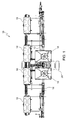
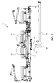
- an agricultural machine 10 is shown in the form of a drill.
- the seeder comprises a first frame part 12 and a second frame part 14.
- the first frame part 12 is designed as a transport frame and the second frame part 14 as a support frame.
- the second Frame part 14 is pivotally mounted about a vertical axis 16 disposed on the first frame part 12, wherein the second frame part 14 is mounted at the same time adjustable in height in the axial direction of the axis 16.
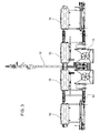
- the carrier frame mounted on the transport frame 12 can be moved from a transport position (according to FIG FIG. 1 and FIG. 2 ) into an operating position (according to FIG. 3 ) are pivoted and lowered.
- Row saw units (not shown) mounted in association with seed and / or fertilizer tanks 18 are mounted on the support frame.
- first hydraulic supply lines 20 and second hydraulic supply lines 22 are arranged on the carrier frame.
- the first hydraulic supply lines 20 can be connected to a hydraulic source arranged on a towing vehicle (not shown), for example an agricultural tractor.
- the first hydraulic supply lines 20 extend from a coupling device 24 on the transport frame 12 of the agricultural machine 10 to a arranged on the transport frame 12 connecting means 26.
- the second hydraulic supply lines 22 extending from the connecting means 26 along the support frame 14 to the respective hydraulic Consumers, in particular the hydraulic cylinders (not shown).
- the connecting device 26 is preferably arranged on the transport frame. However, it is also possible to arrange these on the support frame.
- the transport frame 12 is supported by means of wheels 28 from the ground.
- the connection device 26 comprises a holder 30 (FIG. FIG. 4 ) with a plate 32 ( Figures 5 and 6 ).
- a plurality of rigid hose connections 34 are mounted, which serve to connect the first and second hydraulic supply lines 20, 22.
- the hose connections 34 each have two oppositely disposed and axially aligned connection ends 36, 38, on which connection sockets 40, 42 of the hydraulic supply lines 20, 22 are plugged, wherein the hose connections 34 are mounted parallel to the axis 16 aligned.
- the bearing disc 44 is formed as a circular disc, with a centrally formed through-hole 46 through which the hose connection 34 extends (see FIG. 6 ).
- a thread 50 is formed on which a threaded nut 52 is guided.
- a holding disc 54, 56 arranged, which is in each case designed as a circular disc, and is also provided with a centrally formed through hole 58 and 60, through which the hose connection 34 extends.
- the bearing plate 44 is enclosed between the retaining disks 54 and 56 and the retaining disks 54, 56 are clamped between the shoulder 48 and the threaded nut 52, wherein a retaining washer 54 on the shoulder 48 and the other retaining washer 56 on the threaded nut 52 to Plant comes.
- the outer diameter of the retaining disks 54, 56 are dimensioned such that they each project beyond the outer diameter of the bearing disk 44.
- the plate 32 is provided with a plurality of holes 62, to each of which one of the hose connections 34 is mounted, wherein the holes 62 are formed as through holes.
- One of the holes 62 and a corresponding mounting a hose connection 34 is exemplified in detail in FIG. 6 shown.
- the plate 32 is arranged such that the connecting ends 36, 38 of the hose connection 34 each extend perpendicular to one side of the plate 32, wherein a bearing plate 44 is bordered play in their respective formed in the plate 32 bore 62.
- the thickness of the bearing plate 44 is formed larger than the thickness of the plate 32 and the diameter of the bearing plate 44 is less than the diameter of the bore 32.
- the diameter of the retaining disks 54, 56 chosen larger than the diameter of the bore 32, so that the Halteterion 54, 56 on the one hand, the bearing plate 44 and on the other hand, the bore 62 of the plate 32 project beyond. This results in a playful enclosure of the bearing plate 44, wherein between an edge of the bore 62 and an edge of the bearing plate 44, a radial movement gap 64 and between the retaining disks 54, 56 and the plate 32 each have an axial movement gap 66 is formed.
- the bearing plate 44 is rotatably supported in its circumferential direction on the holder 30, wherein the plate 32 as shown extends radially to the bearing plate 44 and a freedom of movement of the hose connection 34 is limited in the axial direction by the retaining disks 54, 56 and in the radial direction through the bore 62 ,
- connection device 26 for hydraulic supply lines 20, 22 is made possible by simple means that by using conventional rigid hose connections 34 a certain rotational connection for the hydraulic supply lines 20, 22 is provided without having to resort to the conventional rotatable hose connector.
- FIG. 5 is shown as an example, in the above embodiment, a holder with ten formed in the plate 32 holes 62 for mounting ten rigid hose connections 34 and for connecting ten hydraulic supply lines 20 on the first frame member 12 with ten hydraulic supply lines 22 on the second frame member 14 is proposed , This can of course vary and can be changed as desired to a higher or lower number.
- an analog connection device 26 may also be provided for pneumatic or other supply lines filled with a fluid or gas.
Landscapes
- Life Sciences & Earth Sciences (AREA)
- Engineering & Computer Science (AREA)
- Mechanical Engineering (AREA)
- Soil Sciences (AREA)
- Environmental Sciences (AREA)
- Fertilizing (AREA)
- Clamps And Clips (AREA)
Abstract
Description
- Die Erfindung betrifft eine landwirtschaftliche Maschine, mit einem ersten Rahmenteil und einem gegenüber dem ersten Rahmenteil um eine vertikale Achse verschwenkbar angeordneten zweiten Rahmenteil, mit wenigstens einer ersten Versorgungsleitung, die sich entlang des ersten Rahmenteils erstreckt, und wenigstens einer zweiten Versorgungsleitung, die sich entlang des zweiten Rahmenteils erstreckt, wobei eine Verbindungseinrichtung vorgesehen ist, mittels welcher die wenigstens erste und wenigstens zweite Versorgungsleitung miteinander verbunden sind.
- Es sind landwirtschaftliche Maschinen bekannt, insbesondere Sämaschinen oder Bodenbearbeitungsgeräte, die über eine Rahmenkonstruktion verfügen, bei der ein erster Rahmenteil vorgesehen ist, an welchem ein zweiter Rahmenteil axial verschwenkbar gelagert ist. Der erste Rahmenteil kann dabei einen Transportrahmen umfassen, wobei der zweite Rahmenteil einen Trägerrahmen umfasst. An dem Trägerrahmen können Säeinheiten, Pflanzeinheiten, Bodenbearbeitungsgeräte etc. angebaut sein. Die landwirtschaftliche Maschine weist in einer Betriebsstellung, in der sich der Trägerrahmen quer zum Transportrahmen erstreckt, eine Breite auf, die eine zugelassene Transportbreite überragt und muss für den Transport auf der Straße in eine entsprechende Transportstellung gebracht werden. Dazu kann der Trägerrahmen zunächst vertikal angehoben und dann um 90° um eine vertikale Achse gegenüber dem Transportrahmen verschwenkt werden, wobei sich die Breite der landwirtschaftlichen Maschine um ein Vielfaches reduziert. Am Transportrahmen und am Trägerrahmen erstrecken sich Versorgungsleitungen, beispielsweise Hydraulik- und/oder Pneumatikschläuche, die eine hydraulische oder pneumatische Versorgung für die am Trägerrahmen angeordneten Einheiten bzw. Geräte oder Aktuatoren sicherstellen. Üblicherweise werden Schlauchenden der Versorgungsschläuche transportrahmenseitig und trägerrahmenseitig an einer Verbindungseinrichtung, die zum einen eine Schnittstelle zu Wartungszwecken darstellt und zum anderen zur Befestigung und Halterung der Versorgungsleitungen dient, zusammengeführt. Beim Anheben und Verschwenken der Rahmenteile aus der Transportstellung in die Betriebsstellung und umgekehrt werden die Versorgungsleitungen im Bereich der Verbindungseinrichtung, entsprechend verdreht und gebogen und damit sowohl radial als auch axial beansprucht. Insbesondere kann dies zu einem Verwinden der Versorgungsschläuche führen, also einem Verdrehen der Versorgungsschläuche um ihre Längsachse. Ein derartiges Verwinden kann die Lebensdauer der Versorgungsschläuche nachhaltig reduzieren und sollte vermieden werden. Es sind Maßnahmen bekannt, die den Einsatz von drehbaren Schlauchverbindern vorsehen, so dass Schlauchenden von Verbindungsleitungen am Transportrahmen sowie Schlauchenden von Verbindungsleitungen am Trägerrahmen drehbar an einer Verbindungseinrichtung befestigt sind. Derartige drehbare Schlauchverbinder sind jedoch kostspielig. Insbesondere bei einer hohen Anzahl von hydraulischen Versorgungsleitungen an der landwirtschaftlichen Maschine kann dies erhebliche Auswirkungen auf die Gesamtherstellungskosten haben.
- Die der Erfindung zugrunde liegende Aufgabe wird darin gesehen, eine landwirtschaftliche Maschine der eingangs genannten Art anzugeben, durch welches die vorgenannten Probleme überwunden werden.
- Die Aufgabe wird erfindungsgemäß durch die Lehre des Patentanspruchs 1 gelöst. Weitere vorteilhafte Ausgestaltungen und Weiterbildungen der Erfindung gehen aus den Unteransprüchen hervor.
- Erfindungsgemäß umfasst eine landwirtschaftliche Maschine der eingangs genannten Art eine Verbindungseinrichtung mit einer Halterung, an der wenigstes eine starre Schlauchverbindung zur Verbindung der ersten und zweiten Versorgungsleitung angeordnet ist, wobei die Schlauchverbindung zwei axial zueinander ausgerichtete Verbindungsenden umfasst zwischen denen eine Lagerscheibe eingespannt ist, wobei die Lagerscheibe in ihrer Umfangsrichtung verdrehbar an der Halterung gelagert ist. Bei den Versorgungsleitungen kann es sich um hydraulische und/oder pneumatische und/oder gasbefüllte Versorgungsleitungen handeln. Durch das Einspannen einer Lagerscheibe zwischen den Enden einer kostengünstigen starren Schlauchverbindung und die drehbare Lagerung der Lagerscheibe an einer Halterung kann eine kostengünstige und einfache Bauweise einer Verbindungseinrichtung für beispielsweise hydraulische Versorgungsschläuche geschaffen werden, mit der ein Verwinden der Verbindungsleitungen effektiv verhindert oder zumindest reduziert werden kann.
- Die Halterung kann eine sich radial zur Lagerscheibe erstreckende Platte umfassen wobei die Verbindungsenden der Schlauchverbindung sich jeweils senkrecht zu einer Seite der Platte erstrecken und wobei die Lagerscheibe in einer in der Platte ausgebildeten Bohrung spielbehaftet eingefasst ist. Insbesondere die Lagerung der Lagerscheibe in der Bohrung einer Platte oder dergleichen stellt eine kostengünstige und einfach zusammenbaubare Variante dar und vermeidet gänzlich die Verwendung von drehbaren Schlauchverbindern.
- Die Lagerscheibe kann auf einfache Weise durch beidseitig der Platte angeordnete Haltescheiben, die einen Durchmesser der Bohrung radial überspannen, eingefasst sein, wobei die Lagerscheibe zwischen den Haltescheiben eingespannt ist. Sowohl die Lagerscheibe als auch die Haltescheiben sind kreisrund ausgebildet und können spielbehaftet in der Bohrung eingefasst sein, so dass ein Verdrehen der Lagerscheibe und damit auch ein Verdrehen der Schlauchenden der Versorgungsleitungen in Umfangsrichtung ermöglicht wird. Die Haltescheiben spannen die Lagerscheibe ein und überspannen den Durchmesser der Bohrung derart, dass die Lagerscheibe axial gesichert an der Platte gehalten wird. Dabei ist die Lagerscheibe geringfügig dicker ausgebildet als die Platte, wodurch ein gewisses axiales Spiel zwischen Haltescheiben und Platte geschaffen wird.
- An der Schlauchverbindung kann zwischen den Verbindungsenden ein Absatz und ein Gewinde ausgebildet sein, wobei die Haltescheiben und die Lagerscheibe zwischen einer einfachen auf dem Gewinde geführten Gewindemutter und dem Absatz eingespannt werden. Hierdurch wird eine besonders einfache Montage der Verbindungsleitungen an die Halterung geschaffen.
- An der Platte können mehrere nebeneinander angeordnete Bohrungen ausgebildet sein, in denen jeweils eine Schlauchverbindung mittels einer in der jeweiligen Bohrung eingefassten Lagerscheibe angeordnet ist. Damit können eine Vielzahl von Schlauchverbindungen drehbar an der Platte bzw. an der Halterung einer gemeinsamen Verbindungseinrichtung befestigt werden.
- Anhand der Zeichnung, die ein Ausführungsbeispiel der Erfindung zeigt, werden nachfolgend die Erfindung sowie weitere Vorteile und vorteilhafte Weiterbildungen und Ausgestaltungen der Erfindung näher beschrieben und erläutert.
- Es zeigt:
- Fig. 1
- eine schematische Draufsicht einer Sämaschine in einer Transportstellung,
- Fig. 2
- eine schematische Seitenansicht der Sämaschine aus
Figur 1 in der Transportstellung, - Fig. 3
- eine schematische Draufsicht der Sämaschine aus
Figur 1 in einer Betriebsstellung, - Fig. 4
- eine schematische perspektivische Ansicht eines ersten Rahmenteils der Sämaschine aus
Figur 1 , - Fig. 5
- eine vergrößerte schematische perspektivische Ansicht einer Platte einer an dem ersten Rahmenteil ausgebildeten Halterung und
- Fig. 6
- eine vergrößerte schematische Seitenansicht einer in der Platte gemäß
Figur 5 angeordneten Schlauchverbindung. - In den
Figuren 1 bis 3 ist eine landwirtschaftliche Maschine 10 in Form einer Sämaschine dargestellt. Die Sämaschine umfasst einen ersten Rahmenteil 12 und einen zweiten Rahmenteil 14. Der erste Rahmenteil 12 ist als Transportrahmen und der zweite Rahmenteil 14 als Trägerrahmen ausgebildet. Der zweite Rahmenteil 14 ist schwenkbar um eine am ersten Rahmenteil 12 angeordnete vertikale Achse 16 gelagert, wobei der zweite Rahmenteil 14 zugleich in Achsrichtung der Achse 16 höhenverstellbar montiert ist. Auf diese Weise kann der an dem Transportrahmen 12 gelagerte Trägerrahmen von einer Transportstellung (gemäßFigur 1 undFigur 2 ) in eine Betriebsstellung (gemäßFigur 3 ) verschwenkt und abgesenkt werden. Auf dem Trägerrahmen sind Reihensäeinheiten (nicht gezeigt) montiert, die in Verbindung mit Saatgut- und/oder Düngertanks 18 stehen. Zur hydraulischen Versorgung der Sämaschine, insbesondere zur Betätigung von Hydraulikzylindern (nicht gezeigt) am Trägerrahmen, sind am Transportrahmen erste hydraulische Versorgungsleitungen 20 und am Trägerrahmen zweite hydraulische Versorgungsleitungen 22 angeordnet. Die ersten hydraulischen Versorgungsleitungen 20 sind an eine an einem Zugfahrzeug (nicht gezeigt), beispielsweise einem landwirtschaftlichen Schlepper, angeordnete Hydraulikquelle anschließbar. Die ersten hydraulischen Versorgungsleitungen 20 erstrecken sich ausgehend von einer Kupplungseinrichtung 24 am Transportrahmen 12 der landwirtschaftlichen Maschine 10 bis hin zu einer am Transportrahmen 12 angeordneten Verbindungseinrichtung 26. Die zweiten hydraulischen Versorgungsleitungen 22 erstrecken sich ausgehend von der Verbindungseinrichtung 26 entlang des Trägerrahmens 14 zu den jeweiligen hydraulischen Verbrauchern, insbesondere den Hydraulikzylindern (nicht gezeigt). Die Verbindungseinrichtung 26 ist vorzugsweise am Transportrahmen angeordnet. Es ist jedoch auch möglich, diese am Trägerrahmen anzuordnen. Der Transportrahmen 12 stützt sich mittels Räder 28 vom Boden ab. Die Verbindungseinrichtung 26 umfasst eine Halterung 30 (Figur 4 ) mit einer Platte 32 (Figuren 5 und6 ). An der Halterung 30 sind mehrere in sich starre Schlauchverbindungen 34 montiert, die zur Verbindung der ersten und zweiten hydraulischen Versorgungsleitungen 20, 22 dienen. Die Schlauchverbindungen 34 weisen jeweils zwei gegenüber angeordnete und axial zueinander ausgerichtete Verbindungsenden 36, 38 auf, an denen Verbindungsbuchsen 40, 42 der hydraulischen Versorgungsleitungen 20, 22 aufgesteckt sind, wobei die Schlauchverbindungen 34 parallel zur Achse 16 ausgerichtet montiert sind. - Zwischen den Verbindungsenden 36, 38 einer jeden Schlauchverbindung 34 ist eine Lagerscheibe 44 eingespannt. Die Lagerscheibe 44 ist als kreisrunde Scheibe ausgebildet, mit einer zentrisch ausgebildeten Durchgangsöffnung 46, durch welche sich die Schlauchverbindung 34 erstreckt (siehe
Figur 6 ). Zum Einspannen der Lagerscheibe 44 ist an der Schlauchverbindung 34 zwischen den Verbindungsenden einerseits der Lagerscheibe 44 ein Absatz 48 und andererseits der Lagerscheibe 44 ein Gewinde 50 ausgebildet, auf dem eine Gewindemutter 52 geführt ist. Ferner sind beidseitig der Lagerscheibe 44 jeweils eine Haltescheibe 54, 56 angeordnet, die jeweils als kreisrunde Scheibe ausgebildet ist, und ebenfalls mit einer zentrisch ausgebildeten Durchgangsöffnung 58 bzw. 60 versehen ist, durch welche sich die Schlauchverbindung 34 erstreckt. Wie derFigur 6 zu entnehmen ist, ist die Lagerscheibe 44 zwischen den Haltescheiben 54 und 56 eingefasst und die Haltescheiben 54, 56 sind zwischen dem Absatz 48 und der Gewindemutter 52 eingespannt, wobei eine Haltescheibe 54 an dem Absatz 48 und die andere Haltescheibe 56 an der Gewindemutter 52 zu Anlage kommt. Die Außendurchmesser der Haltescheiben 54, 56 sind derart bemessen, dass sie jeweils den Außendurchmesser der Lagerscheibe 44 überragen. - Die Platte 32 ist mit mehreren Bohrungen 62 versehen, an denen jeweils eine der Schlauchverbindungen 34 montiert ist, wobei die Bohrungen 62 als Durchgangsbohrungen ausgebildet sind. Eine der Bohrungen 62 sowie eine entsprechende Montage einer Schlauchverbindung 34 ist exemplarisch detailliert in
Figur 6 dargestellt. Die Platte 32 ist derart angeordnet, dass die Verbindungsenden 36, 38 der Schlauchverbindung 34 sich jeweils senkrecht zu einer Seite der Platte 32 erstrecken, wobei eine Lagerscheibe 44 in ihrer jeweiligen in der Platte 32 ausgebildeten Bohrung 62 spielbehaftet eingefasst ist. Dazu ist die Dicke der Lagerscheibe 44 größer ausgebildet als die Dicke der Platte 32 und der Durchmesser der Lagerscheibe 44 geringer als der Durchmesser der Bohrung 32. Zudem sind die Durchmesser der Haltescheiben 54, 56 größer gewählt als der Durchmesser der Bohrung 32, so dass die Haltescheiben 54, 56 zum einen die Lagerscheibe 44 und zum anderen auch die Bohrung 62 der Platte 32 überragen. Damit ergibt sich eine spielbehaftete Einfassung der Lagerscheibe 44, wobei zwischen einem Rand der Bohrung 62 und einem Rand der Lagerscheibe 44 eine radialer Bewegungsspalt 64 und zwischen den Haltescheiben 54, 56 und der Platte 32 jeweils ein axialer Bewegungsspalt 66 ausgebildet ist. Damit ist die Lagerscheibe 44 in ihrer Umfangsrichtung verdrehbar an der Halterung 30 gelagert, wobei sich die Platte 32 wie dargestellt radial zur Lagerscheibe 44 erstreckt und eine Bewegungsfreiheit der Schlauchverbindung 34 in Axialrichtung durch die Haltescheiben 54, 56 und in Radialrichtung durch die Bohrung 62 beschränkt wird. - Mit der oben ausgeführten Verbindungseinrichtung 26 für hydraulische Versorgungsleitungen 20, 22 wird mit einfachen Mitteln ermöglicht, dass durch Verwendung konventioneller starrer Schlauchverbindungen 34 eine gewisse Drehverbindung für die hydraulischen Versorgungsleitungen 20, 22 bereitgestellt wird, ohne auf die herkömmlichen drehbaren Schlauchverbinder zurückgreifen zu müssen. Wie in
Figur 5 exemplarisch dargestellt ist, wird in dem obigen Ausführungsbeispiel eine Halterung mit zehn in der Platte 32 ausgebildeten Bohrungen 62 zur Montage von zehn starren Schlauchverbindungen 34 bzw. zur Verbindung von zehn hydraulischen Versorgungsleitungen 20 am ersten Rahmenteil 12 mit zehn hydraulischen Versorgungsleitungen 22 am zweiten Rahmenteil 14 vorgeschlagen. Dies kann selbstverständlich variieren und ist beliebig auf eine höhere oder niedrigere Anzahl veränderbar. Durch die spielbehaftete Lagerung der Lagerplatten 44 und damit der Schlauchverbindungen 34 wird eine radiale Bewegungsfreiheit der hydraulischen Versorgungsleitungen 20, 22 derart verbessert bzw. erweitert, dass ein Verwinden der hydraulischen Leitungen 20, 22 beim Verschwenken des ersten Rahmenteils 12 (Transportrahmen) gegenüber dem zweiten Rahmenteil 14 (Trägerrahmen) aus einer Transportstellung in eine Betriebsstellung vermieden wird. Dadurch wird die Beanspruchung der hydraulischen Versorgungsleitungen 20, 22 hinsichtlich Torsion (Verdrehen) deutlich reduziert und die Lebensdauer erhöht. - Auch wenn die Erfindung lediglich anhand eines Ausführungsbeispiels beschrieben wurde, erschließen sich für den Fachmann im Lichte der vorstehenden Beschreibung sowie der Zeichnung viele verschiedenartige Alternativen, Modifikationen und Varianten, die unter die vorliegende Erfindung fallen. So kann beispielsweise eine analoge Verbindungseinrichtung 26 auch für pneumatische oder andere mit einem Fluid oder Gas befüllte Versorgungsleitungen vorgesehen sein.
Claims (5)
- Landwirtschaftliche Maschine (10), mit einem ersten Rahmenteil (12) und einem gegenüber dem ersten Rahmenteil (12) um eine vertikale Achse (16) verschwenkbar angeordneten zweiten Rahmenteil (14), mit wenigstens einer ersten Versorgungsleitung (20), die sich entlang des ersten Rahmenteils (12) erstreckt, und wenigstens einer zweiten Versorgungsleitung (22), die sich entlang des zweiten Rahmenteils (14) erstreckt, wobei eine Verbindungseinrichtung (26) vorgesehen ist, mittels welcher die wenigstens erste und wenigstens zweite Versorgungsleitung (20, 22) miteinander verbunden sind, dadurch gekennzeichnet, dass die Verbindungseinrichtung (26) eine Halterung (30) umfasst, an der wenigstes eine starre Schlauchverbindung (34) zur Verbindung der ersten und zweiten Versorgungsleitung (20, 22) angeordnet ist, wobei die Schlauchverbindung (34) zwei axial zueinander ausgerichtete Verbindungsenden (36, 38) umfasst zwischen denen eine Lagerscheibe (44) eingespannt ist, wobei die Lagerscheibe (44) in ihrer Umfangsrichtung verdrehbar an der Halterung (30) gelagert ist.
- Landwirtschaftliche Maschine (10) nach Anspruch 1, dadurch gekennzeichnet, dass die Halterung (30) eine sich radial zur Lagerscheibe (44) erstreckende Platte (32) umfasst und die Verbindungsenden (36, 38) der Schlauchverbindung (34) sich jeweils senkrecht zu einer Seite der Platte (32) erstrecken, wobei die Lagerscheibe (44) in einer in der Platte ausgebildeten Bohrung (62) spielbehaftet eingefasst ist.
- Landwirtschaftliche Maschine (10) nach Anspruch 2, dadurch gekennzeichnet, dass die Lagerscheibe (44) durch beidseitig der Platte (32) angeordnete Haltescheiben (54, 56), die einen Durchmesser der Bohrung (62) radial überspannen, eingefasst ist, wobei die Lagerscheibe (44) zwischen den Haltescheiben (54, 56) eingespannt ist.
- Landwirtschaftliche Maschine (10) nach Anspruch 3, dadurch gekennzeichnet, dass an der Schlauchverbindung (34) zwischen den Verbindungsenden (36, 38) ein Absatz (48) und ein Gewinde (50) ausgebildet ist, wobei die Haltescheiben (54, 56) und die Lagerscheibe (44) zwischen einer auf dem Gewinde (50) geführten Gewindemutter (52) und dem Absatz (48) eingespannt sind.
- Landwirtschaftliche Maschine (10) nach einem der Ansprüche 2 bis 4, dadurch gekennzeichnet, dass an der Platte (32) mehrere nebeneinander angeordnete Bohrungen (62) ausgebildet sind in denen jeweils eine Schlauchverbindung (34) mittels einer in der jeweiligen Bohrung (62) eingefassten Lagerscheibe (44) angeordnet ist.
Applications Claiming Priority (1)
| Application Number | Priority Date | Filing Date | Title |
|---|---|---|---|
| DE201310221606 DE102013221606A1 (de) | 2013-10-24 | 2013-10-24 | Landwirtschaftliche Maschine |
Publications (2)
| Publication Number | Publication Date |
|---|---|
| EP2865255A1 true EP2865255A1 (de) | 2015-04-29 |
| EP2865255B1 EP2865255B1 (de) | 2018-03-28 |
Family
ID=51752035
Family Applications (1)
| Application Number | Title | Priority Date | Filing Date |
|---|---|---|---|
| EP14189854.4A Active EP2865255B1 (de) | 2013-10-24 | 2014-10-22 | Landwirtschaftliche Maschine |
Country Status (4)
| Country | Link |
|---|---|
| EP (1) | EP2865255B1 (de) |
| AR (1) | AR098174A1 (de) |
| DE (1) | DE102013221606A1 (de) |
| EA (1) | EA201401000A1 (de) |
Cited By (2)
| Publication number | Priority date | Publication date | Assignee | Title |
|---|---|---|---|---|
| EP3827651A1 (de) * | 2019-11-29 | 2021-06-02 | CNH Industrial Sweden AB | Rahmen für landwirtschaftliche geräte |
| EP3827650A1 (de) * | 2019-11-29 | 2021-06-02 | CNH Industrial Sweden AB | Rahmen für landwirtschaftliche geräte |
Citations (2)
| Publication number | Priority date | Publication date | Assignee | Title |
|---|---|---|---|---|
| EP0836043A1 (de) * | 1996-10-14 | 1998-04-15 | Karl-Heinz Prange | Verbindungselement zum Verbinden von Schlauch- und Rohrleitungsabschnitten |
| US20090229501A1 (en) * | 2008-03-14 | 2009-09-17 | Cnh America Llc | Planter with direct hydraulic seed drive |
Family Cites Families (4)
| Publication number | Priority date | Publication date | Assignee | Title |
|---|---|---|---|---|
| CH129967A (de) * | 1927-09-09 | 1929-01-02 | Hans Burkhardt | Einrichtung zur gelenkigen Verbindung von Leitungen, insbesondere von Leitungen zwischen zusammengekuppelten Fahrzeugen. |
| AT377897B (de) * | 1983-08-24 | 1985-05-10 | Roehren Und Pumpemwerk Rudolf | Auslegerstativ |
| DE102011053800A1 (de) * | 2011-09-20 | 2013-03-21 | Invite GmbH | Haltegestell für eine Multikupplung zum Befüllen und/oder Entleeren eines Chemieanlagencontainers |
| DE202012101628U1 (de) * | 2012-05-03 | 2012-06-21 | Ibs Gmbh Schlauch- Und Armaturentechnik | Verteiler zur Verbindung einer Hauptrohrleitung mit weiterführenden Leitungen |
-
2013
- 2013-10-24 DE DE201310221606 patent/DE102013221606A1/de not_active Withdrawn
-
2014
- 2014-10-09 EA EA201401000A patent/EA201401000A1/ru unknown
- 2014-10-22 EP EP14189854.4A patent/EP2865255B1/de active Active
- 2014-10-23 AR ARP140103991A patent/AR098174A1/es active IP Right Grant
Patent Citations (2)
| Publication number | Priority date | Publication date | Assignee | Title |
|---|---|---|---|---|
| EP0836043A1 (de) * | 1996-10-14 | 1998-04-15 | Karl-Heinz Prange | Verbindungselement zum Verbinden von Schlauch- und Rohrleitungsabschnitten |
| US20090229501A1 (en) * | 2008-03-14 | 2009-09-17 | Cnh America Llc | Planter with direct hydraulic seed drive |
Cited By (2)
| Publication number | Priority date | Publication date | Assignee | Title |
|---|---|---|---|---|
| EP3827651A1 (de) * | 2019-11-29 | 2021-06-02 | CNH Industrial Sweden AB | Rahmen für landwirtschaftliche geräte |
| EP3827650A1 (de) * | 2019-11-29 | 2021-06-02 | CNH Industrial Sweden AB | Rahmen für landwirtschaftliche geräte |
Also Published As
| Publication number | Publication date |
|---|---|
| AR098174A1 (es) | 2016-05-04 |
| DE102013221606A1 (de) | 2015-04-30 |
| EA201401000A1 (ru) | 2015-04-30 |
| EP2865255B1 (de) | 2018-03-28 |
Similar Documents
| Publication | Publication Date | Title |
|---|---|---|
| EP1541003B1 (de) | Überlastsicherung, insbesondere für ein Bodenbearbeitungswerkzeug | |
| EP2865255B1 (de) | Landwirtschaftliche Maschine | |
| DE112009002681T5 (de) | Stabilisator und Abstandsmittel | |
| DE102004060591A1 (de) | Tank für kryogene Medien sowie Verfahren und Vorrichtung zu dessen Zusammenbau | |
| DE102012005027A1 (de) | Bodenbearbeitungsgerät und Federzinkenlagerelement | |
| DE102014201519B4 (de) | Mähgerat | |
| DE202020004233U1 (de) | Zusatzradverstellvorrichtung | |
| DE102010000620A1 (de) | Achslenker für eine luftgefederte Fahrzeugachse | |
| EP3831176B1 (de) | Aufhängungsvorrichtung | |
| DE60315831T2 (de) | Landmaschine | |
| EP4104655A1 (de) | Bodenbearbeitungsgerät | |
| DE102017105403A1 (de) | Packerwalze zur Bodenbearbeitung | |
| EP2965602A1 (de) | Sämaschine | |
| EP1961285A1 (de) | Sämaschine | |
| EP1500322A1 (de) | Vorrichtung zur Bodenbearbeitung | |
| DE102011080461B4 (de) | Landwirtschaftliche Maschine | |
| DE202012012861U1 (de) | Roderechen | |
| DE63028C (de) | Gelenkscheibenegge mit umstell- j baren Scheibensätzen | |
| DE102018206308A1 (de) | Lagerelement und Lageranordnung einer landwirtschaftlichen Maschine | |
| EP3603366B1 (de) | Arretiervorrichtung für ein zugpendel | |
| EP2173149A1 (de) | Scheibensystem für eine scheibenegge | |
| EP3437447B1 (de) | Aufhängungsvorrichtung | |
| EP3367775A1 (de) | Landwirtschaftlicher maschinenrahmen | |
| DE69211168T2 (de) | Bodenbearbeitungsmaschine | |
| DE102014020151B4 (de) | Mähgerät |
Legal Events
| Date | Code | Title | Description |
|---|---|---|---|
| PUAI | Public reference made under article 153(3) epc to a published international application that has entered the european phase |
Free format text: ORIGINAL CODE: 0009012 |
|
| 17P | Request for examination filed |
Effective date: 20141022 |
|
| AK | Designated contracting states |
Kind code of ref document: A1 Designated state(s): AL AT BE BG CH CY CZ DE DK EE ES FI FR GB GR HR HU IE IS IT LI LT LU LV MC MK MT NL NO PL PT RO RS SE SI SK SM TR |
|
| AX | Request for extension of the european patent |
Extension state: BA ME |
|
| R17P | Request for examination filed (corrected) |
Effective date: 20151029 |
|
| RBV | Designated contracting states (corrected) |
Designated state(s): AL AT BE BG CH CY CZ DE DK EE ES FI FR GB GR HR HU IE IS IT LI LT LU LV MC MK MT NL NO PL PT RO RS SE SI SK SM TR |
|
| RIC1 | Information provided on ipc code assigned before grant |
Ipc: A01B 73/06 20060101AFI20170831BHEP |
|
| GRAP | Despatch of communication of intention to grant a patent |
Free format text: ORIGINAL CODE: EPIDOSNIGR1 |
|
| INTG | Intention to grant announced |
Effective date: 20171020 |
|
| GRAS | Grant fee paid |
Free format text: ORIGINAL CODE: EPIDOSNIGR3 |
|
| GRAA | (expected) grant |
Free format text: ORIGINAL CODE: 0009210 |
|
| AK | Designated contracting states |
Kind code of ref document: B1 Designated state(s): AL AT BE BG CH CY CZ DE DK EE ES FI FR GB GR HR HU IE IS IT LI LT LU LV MC MK MT NL NO PL PT RO RS SE SI SK SM TR |
|
| REG | Reference to a national code |
Ref country code: GB Ref legal event code: FG4D Free format text: NOT ENGLISH |
|
| REG | Reference to a national code |
Ref country code: CH Ref legal event code: EP |
|
| REG | Reference to a national code |
Ref country code: AT Ref legal event code: REF Ref document number: 982504 Country of ref document: AT Kind code of ref document: T Effective date: 20180415 |
|
| REG | Reference to a national code |
Ref country code: IE Ref legal event code: FG4D Free format text: LANGUAGE OF EP DOCUMENT: GERMAN |
|
| REG | Reference to a national code |
Ref country code: DE Ref legal event code: R096 Ref document number: 502014007745 Country of ref document: DE |
|
| PG25 | Lapsed in a contracting state [announced via postgrant information from national office to epo] |
Ref country code: LT Free format text: LAPSE BECAUSE OF FAILURE TO SUBMIT A TRANSLATION OF THE DESCRIPTION OR TO PAY THE FEE WITHIN THE PRESCRIBED TIME-LIMIT Effective date: 20180328 Ref country code: HR Free format text: LAPSE BECAUSE OF FAILURE TO SUBMIT A TRANSLATION OF THE DESCRIPTION OR TO PAY THE FEE WITHIN THE PRESCRIBED TIME-LIMIT Effective date: 20180328 Ref country code: NO Free format text: LAPSE BECAUSE OF FAILURE TO SUBMIT A TRANSLATION OF THE DESCRIPTION OR TO PAY THE FEE WITHIN THE PRESCRIBED TIME-LIMIT Effective date: 20180628 Ref country code: FI Free format text: LAPSE BECAUSE OF FAILURE TO SUBMIT A TRANSLATION OF THE DESCRIPTION OR TO PAY THE FEE WITHIN THE PRESCRIBED TIME-LIMIT Effective date: 20180328 |
|
| REG | Reference to a national code |
Ref country code: NL Ref legal event code: MP Effective date: 20180328 |
|
| REG | Reference to a national code |
Ref country code: LT Ref legal event code: MG4D |
|
| PG25 | Lapsed in a contracting state [announced via postgrant information from national office to epo] |
Ref country code: RS Free format text: LAPSE BECAUSE OF FAILURE TO SUBMIT A TRANSLATION OF THE DESCRIPTION OR TO PAY THE FEE WITHIN THE PRESCRIBED TIME-LIMIT Effective date: 20180328 Ref country code: SE Free format text: LAPSE BECAUSE OF FAILURE TO SUBMIT A TRANSLATION OF THE DESCRIPTION OR TO PAY THE FEE WITHIN THE PRESCRIBED TIME-LIMIT Effective date: 20180328 Ref country code: LV Free format text: LAPSE BECAUSE OF FAILURE TO SUBMIT A TRANSLATION OF THE DESCRIPTION OR TO PAY THE FEE WITHIN THE PRESCRIBED TIME-LIMIT Effective date: 20180328 Ref country code: GR Free format text: LAPSE BECAUSE OF FAILURE TO SUBMIT A TRANSLATION OF THE DESCRIPTION OR TO PAY THE FEE WITHIN THE PRESCRIBED TIME-LIMIT Effective date: 20180629 Ref country code: BG Free format text: LAPSE BECAUSE OF FAILURE TO SUBMIT A TRANSLATION OF THE DESCRIPTION OR TO PAY THE FEE WITHIN THE PRESCRIBED TIME-LIMIT Effective date: 20180628 |
|
| PG25 | Lapsed in a contracting state [announced via postgrant information from national office to epo] |
Ref country code: MT Free format text: LAPSE BECAUSE OF FAILURE TO SUBMIT A TRANSLATION OF THE DESCRIPTION OR TO PAY THE FEE WITHIN THE PRESCRIBED TIME-LIMIT Effective date: 20180328 |
|
| REG | Reference to a national code |
Ref country code: FR Ref legal event code: PLFP Year of fee payment: 5 |
|
| PG25 | Lapsed in a contracting state [announced via postgrant information from national office to epo] |
Ref country code: ES Free format text: LAPSE BECAUSE OF FAILURE TO SUBMIT A TRANSLATION OF THE DESCRIPTION OR TO PAY THE FEE WITHIN THE PRESCRIBED TIME-LIMIT Effective date: 20180328 Ref country code: AL Free format text: LAPSE BECAUSE OF FAILURE TO SUBMIT A TRANSLATION OF THE DESCRIPTION OR TO PAY THE FEE WITHIN THE PRESCRIBED TIME-LIMIT Effective date: 20180328 Ref country code: NL Free format text: LAPSE BECAUSE OF FAILURE TO SUBMIT A TRANSLATION OF THE DESCRIPTION OR TO PAY THE FEE WITHIN THE PRESCRIBED TIME-LIMIT Effective date: 20180328 Ref country code: IT Free format text: LAPSE BECAUSE OF FAILURE TO SUBMIT A TRANSLATION OF THE DESCRIPTION OR TO PAY THE FEE WITHIN THE PRESCRIBED TIME-LIMIT Effective date: 20180328 Ref country code: EE Free format text: LAPSE BECAUSE OF FAILURE TO SUBMIT A TRANSLATION OF THE DESCRIPTION OR TO PAY THE FEE WITHIN THE PRESCRIBED TIME-LIMIT Effective date: 20180328 Ref country code: RO Free format text: LAPSE BECAUSE OF FAILURE TO SUBMIT A TRANSLATION OF THE DESCRIPTION OR TO PAY THE FEE WITHIN THE PRESCRIBED TIME-LIMIT Effective date: 20180328 Ref country code: PL Free format text: LAPSE BECAUSE OF FAILURE TO SUBMIT A TRANSLATION OF THE DESCRIPTION OR TO PAY THE FEE WITHIN THE PRESCRIBED TIME-LIMIT Effective date: 20180328 |
|
| PG25 | Lapsed in a contracting state [announced via postgrant information from national office to epo] |
Ref country code: SK Free format text: LAPSE BECAUSE OF FAILURE TO SUBMIT A TRANSLATION OF THE DESCRIPTION OR TO PAY THE FEE WITHIN THE PRESCRIBED TIME-LIMIT Effective date: 20180328 Ref country code: CZ Free format text: LAPSE BECAUSE OF FAILURE TO SUBMIT A TRANSLATION OF THE DESCRIPTION OR TO PAY THE FEE WITHIN THE PRESCRIBED TIME-LIMIT Effective date: 20180328 Ref country code: SM Free format text: LAPSE BECAUSE OF FAILURE TO SUBMIT A TRANSLATION OF THE DESCRIPTION OR TO PAY THE FEE WITHIN THE PRESCRIBED TIME-LIMIT Effective date: 20180328 |
|
| PG25 | Lapsed in a contracting state [announced via postgrant information from national office to epo] |
Ref country code: PT Free format text: LAPSE BECAUSE OF FAILURE TO SUBMIT A TRANSLATION OF THE DESCRIPTION OR TO PAY THE FEE WITHIN THE PRESCRIBED TIME-LIMIT Effective date: 20180730 |
|
| REG | Reference to a national code |
Ref country code: DE Ref legal event code: R097 Ref document number: 502014007745 Country of ref document: DE |
|
| PG25 | Lapsed in a contracting state [announced via postgrant information from national office to epo] |
Ref country code: DK Free format text: LAPSE BECAUSE OF FAILURE TO SUBMIT A TRANSLATION OF THE DESCRIPTION OR TO PAY THE FEE WITHIN THE PRESCRIBED TIME-LIMIT Effective date: 20180328 |
|
| PLBE | No opposition filed within time limit |
Free format text: ORIGINAL CODE: 0009261 |
|
| STAA | Information on the status of an ep patent application or granted ep patent |
Free format text: STATUS: NO OPPOSITION FILED WITHIN TIME LIMIT |
|
| 26N | No opposition filed |
Effective date: 20190103 |
|
| PG25 | Lapsed in a contracting state [announced via postgrant information from national office to epo] |
Ref country code: SI Free format text: LAPSE BECAUSE OF FAILURE TO SUBMIT A TRANSLATION OF THE DESCRIPTION OR TO PAY THE FEE WITHIN THE PRESCRIBED TIME-LIMIT Effective date: 20180328 |
|
| REG | Reference to a national code |
Ref country code: CH Ref legal event code: PL |
|
| GBPC | Gb: european patent ceased through non-payment of renewal fee |
Effective date: 20181022 |
|
| REG | Reference to a national code |
Ref country code: BE Ref legal event code: MM Effective date: 20181031 |
|
| PG25 | Lapsed in a contracting state [announced via postgrant information from national office to epo] |
Ref country code: LU Free format text: LAPSE BECAUSE OF NON-PAYMENT OF DUE FEES Effective date: 20181022 Ref country code: MC Free format text: LAPSE BECAUSE OF FAILURE TO SUBMIT A TRANSLATION OF THE DESCRIPTION OR TO PAY THE FEE WITHIN THE PRESCRIBED TIME-LIMIT Effective date: 20180328 |
|
| REG | Reference to a national code |
Ref country code: IE Ref legal event code: MM4A |
|
| PG25 | Lapsed in a contracting state [announced via postgrant information from national office to epo] |
Ref country code: LI Free format text: LAPSE BECAUSE OF NON-PAYMENT OF DUE FEES Effective date: 20181031 Ref country code: BE Free format text: LAPSE BECAUSE OF NON-PAYMENT OF DUE FEES Effective date: 20181031 Ref country code: CH Free format text: LAPSE BECAUSE OF NON-PAYMENT OF DUE FEES Effective date: 20181031 |
|
| PG25 | Lapsed in a contracting state [announced via postgrant information from national office to epo] |
Ref country code: GB Free format text: LAPSE BECAUSE OF NON-PAYMENT OF DUE FEES Effective date: 20181022 Ref country code: IE Free format text: LAPSE BECAUSE OF NON-PAYMENT OF DUE FEES Effective date: 20181022 |
|
| PG25 | Lapsed in a contracting state [announced via postgrant information from national office to epo] |
Ref country code: TR Free format text: LAPSE BECAUSE OF FAILURE TO SUBMIT A TRANSLATION OF THE DESCRIPTION OR TO PAY THE FEE WITHIN THE PRESCRIBED TIME-LIMIT Effective date: 20180328 |
|
| PG25 | Lapsed in a contracting state [announced via postgrant information from national office to epo] |
Ref country code: MK Free format text: LAPSE BECAUSE OF NON-PAYMENT OF DUE FEES Effective date: 20180328 Ref country code: CY Free format text: LAPSE BECAUSE OF FAILURE TO SUBMIT A TRANSLATION OF THE DESCRIPTION OR TO PAY THE FEE WITHIN THE PRESCRIBED TIME-LIMIT Effective date: 20180328 Ref country code: HU Free format text: LAPSE BECAUSE OF FAILURE TO SUBMIT A TRANSLATION OF THE DESCRIPTION OR TO PAY THE FEE WITHIN THE PRESCRIBED TIME-LIMIT; INVALID AB INITIO Effective date: 20141022 |
|
| PG25 | Lapsed in a contracting state [announced via postgrant information from national office to epo] |
Ref country code: IS Free format text: LAPSE BECAUSE OF FAILURE TO SUBMIT A TRANSLATION OF THE DESCRIPTION OR TO PAY THE FEE WITHIN THE PRESCRIBED TIME-LIMIT Effective date: 20180728 |
|
| REG | Reference to a national code |
Ref country code: AT Ref legal event code: MM01 Ref document number: 982504 Country of ref document: AT Kind code of ref document: T Effective date: 20191022 |
|
| PG25 | Lapsed in a contracting state [announced via postgrant information from national office to epo] |
Ref country code: AT Free format text: LAPSE BECAUSE OF NON-PAYMENT OF DUE FEES Effective date: 20191022 |
|
| PGFP | Annual fee paid to national office [announced via postgrant information from national office to epo] |
Ref country code: DE Payment date: 20240919 Year of fee payment: 11 |
|
| PGFP | Annual fee paid to national office [announced via postgrant information from national office to epo] |
Ref country code: FR Payment date: 20241025 Year of fee payment: 11 |