EP2865317A1 - Kurvensensor - Google Patents
Kurvensensor Download PDFInfo
- Publication number
- EP2865317A1 EP2865317A1 EP20130807866 EP13807866A EP2865317A1 EP 2865317 A1 EP2865317 A1 EP 2865317A1 EP 20130807866 EP20130807866 EP 20130807866 EP 13807866 A EP13807866 A EP 13807866A EP 2865317 A1 EP2865317 A1 EP 2865317A1
- Authority
- EP
- European Patent Office
- Prior art keywords
- curve
- light
- unit
- sensor according
- curved state
- Prior art date
- Legal status (The legal status is an assumption and is not a legal conclusion. Google has not performed a legal analysis and makes no representation as to the accuracy of the status listed.)
- Withdrawn
Links
- 238000005259 measurement Methods 0.000 claims abstract description 107
- 238000001514 detection method Methods 0.000 claims abstract description 69
- 230000005540 biological transmission Effects 0.000 claims abstract description 6
- 230000008859 change Effects 0.000 claims abstract description 5
- 230000003287 optical effect Effects 0.000 claims description 38
- 239000013307 optical fiber Substances 0.000 claims description 26
- 238000003780 insertion Methods 0.000 claims description 8
- 230000037431 insertion Effects 0.000 claims description 8
- 230000007306 turnover Effects 0.000 claims description 5
- 239000000835 fiber Substances 0.000 description 107
- 230000004048 modification Effects 0.000 description 33
- 238000012986 modification Methods 0.000 description 33
- 238000010586 diagram Methods 0.000 description 18
- 239000000523 sample Substances 0.000 description 13
- 238000005253 cladding Methods 0.000 description 6
- 239000011347 resin Substances 0.000 description 5
- 229920005989 resin Polymers 0.000 description 5
- 239000000853 adhesive Substances 0.000 description 4
- 230000007246 mechanism Effects 0.000 description 4
- 230000008901 benefit Effects 0.000 description 2
- 239000003814 drug Substances 0.000 description 2
- 229940079593 drug Drugs 0.000 description 2
- 230000000694 effects Effects 0.000 description 2
- 239000011521 glass Substances 0.000 description 2
- 230000002401 inhibitory effect Effects 0.000 description 2
- XLYOFNOQVPJJNP-UHFFFAOYSA-N water Substances O XLYOFNOQVPJJNP-UHFFFAOYSA-N 0.000 description 2
- 239000006096 absorbing agent Substances 0.000 description 1
- 230000003044 adaptive effect Effects 0.000 description 1
- 230000002411 adverse Effects 0.000 description 1
- 239000011230 binding agent Substances 0.000 description 1
- 210000001124 body fluid Anatomy 0.000 description 1
- 239000010839 body fluid Substances 0.000 description 1
- 238000007599 discharging Methods 0.000 description 1
- 230000004927 fusion Effects 0.000 description 1
- 238000004519 manufacturing process Methods 0.000 description 1
- 239000000463 material Substances 0.000 description 1
- 239000002184 metal Substances 0.000 description 1
- 238000000034 method Methods 0.000 description 1
- 230000008569 process Effects 0.000 description 1
- 230000035945 sensitivity Effects 0.000 description 1
- 229910000679 solder Inorganic materials 0.000 description 1
Images





Classifications
-
- G—PHYSICS
- G01—MEASURING; TESTING
- G01B—MEASURING LENGTH, THICKNESS OR SIMILAR LINEAR DIMENSIONS; MEASURING ANGLES; MEASURING AREAS; MEASURING IRREGULARITIES OF SURFACES OR CONTOURS
- G01B11/00—Measuring arrangements characterised by the use of optical techniques
- G01B11/24—Measuring arrangements characterised by the use of optical techniques for measuring contours or curvatures
-
- A—HUMAN NECESSITIES
- A61—MEDICAL OR VETERINARY SCIENCE; HYGIENE
- A61B—DIAGNOSIS; SURGERY; IDENTIFICATION
- A61B1/00—Instruments for performing medical examinations of the interior of cavities or tubes of the body by visual or photographical inspection, e.g. endoscopes; Illuminating arrangements therefor
- A61B1/00131—Accessories for endoscopes
- A61B1/00135—Oversleeves mounted on the endoscope prior to insertion
-
- A—HUMAN NECESSITIES
- A61—MEDICAL OR VETERINARY SCIENCE; HYGIENE
- A61B—DIAGNOSIS; SURGERY; IDENTIFICATION
- A61B1/00—Instruments for performing medical examinations of the interior of cavities or tubes of the body by visual or photographical inspection, e.g. endoscopes; Illuminating arrangements therefor
- A61B1/005—Flexible endoscopes
- A61B1/009—Flexible endoscopes with bending or curvature detection of the insertion part
-
- A—HUMAN NECESSITIES
- A61—MEDICAL OR VETERINARY SCIENCE; HYGIENE
- A61B—DIAGNOSIS; SURGERY; IDENTIFICATION
- A61B1/00—Instruments for performing medical examinations of the interior of cavities or tubes of the body by visual or photographical inspection, e.g. endoscopes; Illuminating arrangements therefor
- A61B1/00002—Operational features of endoscopes
- A61B1/00011—Operational features of endoscopes characterised by signal transmission
- A61B1/00013—Operational features of endoscopes characterised by signal transmission using optical means
-
- A—HUMAN NECESSITIES
- A61—MEDICAL OR VETERINARY SCIENCE; HYGIENE
- A61B—DIAGNOSIS; SURGERY; IDENTIFICATION
- A61B1/00—Instruments for performing medical examinations of the interior of cavities or tubes of the body by visual or photographical inspection, e.g. endoscopes; Illuminating arrangements therefor
- A61B1/012—Instruments for performing medical examinations of the interior of cavities or tubes of the body by visual or photographical inspection, e.g. endoscopes; Illuminating arrangements therefor characterised by internal passages or accessories therefor
- A61B1/018—Instruments for performing medical examinations of the interior of cavities or tubes of the body by visual or photographical inspection, e.g. endoscopes; Illuminating arrangements therefor characterised by internal passages or accessories therefor for receiving instruments
-
- A—HUMAN NECESSITIES
- A61—MEDICAL OR VETERINARY SCIENCE; HYGIENE
- A61B—DIAGNOSIS; SURGERY; IDENTIFICATION
- A61B5/00—Measuring for diagnostic purposes; Identification of persons
- A61B5/103—Measuring devices for testing the shape, pattern, colour, size or movement of the body or parts thereof, for diagnostic purposes
- A61B5/107—Measuring physical dimensions, e.g. size of the entire body or parts thereof
- A61B5/1076—Measuring physical dimensions, e.g. size of the entire body or parts thereof for measuring dimensions inside body cavities, e.g. using catheters
-
- G—PHYSICS
- G01—MEASURING; TESTING
- G01B—MEASURING LENGTH, THICKNESS OR SIMILAR LINEAR DIMENSIONS; MEASURING ANGLES; MEASURING AREAS; MEASURING IRREGULARITIES OF SURFACES OR CONTOURS
- G01B11/00—Measuring arrangements characterised by the use of optical techniques
- G01B11/16—Measuring arrangements characterised by the use of optical techniques for measuring the deformation in a solid, e.g. optical strain gauge
- G01B11/18—Measuring arrangements characterised by the use of optical techniques for measuring the deformation in a solid, e.g. optical strain gauge using photoelastic elements
-
- G—PHYSICS
- G02—OPTICS
- G02B—OPTICAL ELEMENTS, SYSTEMS OR APPARATUS
- G02B23/00—Telescopes, e.g. binoculars; Periscopes; Instruments for viewing the inside of hollow bodies; Viewfinders; Optical aiming or sighting devices
- G02B23/24—Instruments or systems for viewing the inside of hollow bodies, e.g. fibrescopes
- G02B23/2407—Optical details
- G02B23/2461—Illumination
- G02B23/2469—Illumination using optical fibres
-
- G—PHYSICS
- G02—OPTICS
- G02B—OPTICAL ELEMENTS, SYSTEMS OR APPARATUS
- G02B23/00—Telescopes, e.g. binoculars; Periscopes; Instruments for viewing the inside of hollow bodies; Viewfinders; Optical aiming or sighting devices
- G02B23/24—Instruments or systems for viewing the inside of hollow bodies, e.g. fibrescopes
- G02B23/2476—Non-optical details, e.g. housings, mountings, supports
-
- G—PHYSICS
- G02—OPTICS
- G02B—OPTICAL ELEMENTS, SYSTEMS OR APPARATUS
- G02B23/00—Telescopes, e.g. binoculars; Periscopes; Instruments for viewing the inside of hollow bodies; Viewfinders; Optical aiming or sighting devices
- G02B23/24—Instruments or systems for viewing the inside of hollow bodies, e.g. fibrescopes
- G02B23/26—Instruments or systems for viewing the inside of hollow bodies, e.g. fibrescopes using light guides
-
- A—HUMAN NECESSITIES
- A61—MEDICAL OR VETERINARY SCIENCE; HYGIENE
- A61B—DIAGNOSIS; SURGERY; IDENTIFICATION
- A61B1/00—Instruments for performing medical examinations of the interior of cavities or tubes of the body by visual or photographical inspection, e.g. endoscopes; Illuminating arrangements therefor
- A61B1/00163—Optical arrangements
- A61B1/00165—Optical arrangements with light-conductive means, e.g. fibre optics
Definitions
- the present invention relates to a curve sensor to detect the curved state of a curving measurement target.
- a curve sensor to detect the curved state (curving angle or curving direction) of a curving measurement target is generally known.
- a curve sensor guides light having a predetermined optical characteristic emitted from a light source to an optical fiber provided with a curved state detecting unit.
- the light amount in the curved state detecting unit changes in accordance with the curving angle and curving direction of the optical fiber. Based on the change in the light amount, the curved state of the optical fiber, thereby the curved state of the curving measurement target is detected.
- Patent Literature 1 has disclosed an endoscope insertion shape detection probe to detect the shape of an insertion tube of an endoscope.
- the probe comprises a probe body, and a module connected to the probe body.
- the outer diameter of the probe body is formed to be less than the inner diameter of a forceps channel in the endoscope.
- the probe body comprises a light supply fiber, curvature detection fibers provided with light loss portions, and a mirror disposed at the distal ends of the light supply fiber and the curvature detection fibers.
- the probe body When the insertion shape of the endoscope is detected, the probe body is first inserted into the forceps channel in the endoscope. Light emitted from a light source is then guided by the light supply fiber and reflected by the mirror at the distal end. The reflected light is then guided by the curvature detection fibers, and received on a module side from the proximal end of the curvature detection fibers. The amount of the light guided by the curvature detection fibers has changed by the leakage of the light in the light loss portions, and the curving angle or curving direction of the curvature detection fibers at the light loss portions is detected on the basis of the amount of the light received on the module side. In this way, the insertion shape of the endoscope in which the probe body is inserted is detected.
- Patent Literature 1 Jpn. Pat. Appln. KOKAI Publication No. 2007-44412
- the probe body is inserted into the forceps channel in the endoscope to detect the insertion shape of the endoscope. Therefore, the endoscope insertion shape detection probe is not applicable to an endoscope in which a longitudinally extending through-hole such as a channel is not provided. That is, it is difficult to incorporate the probe into a universal curving measurement target. It is also difficult to incorporate the probe into a measurement target having a relatively small diameter such as a catheter.
- a curve sensor which measures the curving of a curving measurement target
- the curve sensor characterized by comprising a light supply unit which guides light, a curve measurement unit which comprises a curved state detection unit and which is configured to measure the curved state of the measurement target by the change in the amount of light output through the curved state detection unit, a light transmission unit which transmits the light from the light supply unit to the curve measurement unit and a holding portion which holds the light supply unit and the curve measurement unit at predetermined positions on the measurement target.
- FIG. 1 is a diagram schematically showing a curve sensor 1 according to the first embodiment.
- the curve sensor 1 comprises a cylindrical body 1A and two sensor units 1B1 and 1B2.
- the cylindrical body 1A comprises a cylindrical first elastic member 2 and a cylindrical second elastic member 3.
- the inner diameter of the first elastic member 2 is set to be substantially equal to the outer diameter of the second elastic member 3.
- the first elastic member 2 is engaged with the outer side of the second elastic member 3 in an externally fit state, and the outer circumferential surface of the second elastic member 3 is joined to the inner circumferential surface of the first elastic member 2.
- a curving measurement target 100 such as a flexible endoscope having a flexible curving portion, a forceps, or a catheter is inserted into the inside of the second elastic member 3.
- the inner diameter of the second elastic member 3 is set to be substantially adaptive to the outer diameter of the measurement target 100 to be inserted.
- the curve sensor 1 When the curve sensor 1 is attached to the curving measurement target 100, the inner circumferential surface of the second elastic member 3 is joined to the outer circumferential surface of the curving measurement target 100. At this time, the curve sensor 1 is held and fixed to the outer circumferential surface of the curving measurement target 100 by the elastic force of the first and second elastic members 2 and 3.
- FIG. 2 is a perspective view schematically showing the curve sensor 1 where the first elastic member 2 is removed.
- FIG. 3 is a cross sectional view showing the curve sensor 1 taken along the line A-A in FIG. 1 .
- the curve sensor 1 comprises a light supply fiber 4 as a light supply unit, a sensor fiber 6 as a curve measurement unit provided with a curved state detection unit 5, and a reflecting member 7 as a light transmission unit.
- the light supply fiber 4, the sensor fiber 6, and the reflecting member 7 are inserted between the first elastic member 2 and the second elastic member 3, and in this state, held and fixed by the elastic force of the first and second elastic members 2 and 3.
- the light supply fiber 4, the sensor fiber 6, and the reflecting member 7 may be further fixed by an adhesive agent not shown.
- the light supply fiber 4 and the sensor fiber 6 are, for example, optical fibers each including, for example, a glass core and a resin cladding.
- the curved state detection unit 5 is formed by, for example, providing a cutout in the cladding at a predetermined position of the sensor fiber 6 and filling the cutout with a resin having a predetermined optical characteristic (e.g. an absorber or fluorescent material which absorbs light of a predetermined wavelength).
- the reflecting member 7 is disposed on the longitudinally distal side of the light supply fiber 4 and the sensor fiber 6, and reflects the light guided from the light supply fiber 4 to the sensor fiber 6. That is, the light supply fiber 4 and the sensor fiber 6 are optically connected to each other via the reflecting member 7.
- the reflecting member 7 is, for example, a prism, and is a member which includes two mirrors that intersect at right angles with each other and which reverses the direction of light 180 degrees.
- a light source 8 is connected to the longitudinally proximal side of the light supply fiber 4.
- the light source 8 is, for example, a laser light source, and emits laser light having a predetermined wavelength to the light supply fiber 4.
- a photodetector 9 is connected to the longitudinally proximal side of the sensor fiber 6. The photodetector 9 receives the light guided by the light supply fiber 4, reflected by the reflecting member 7, and guided by the sensor fiber 6. That is, the photodetector 9 is a light receiving unit which receives a light signal (curve signal) regarding the curved state from the sensor fiber 6.
- FIG. 1 to FIG. 3 two light supply fibers 4a and 4b, two sensor fibers 6a and 6b respectively provided with curved state detection units 5a and 5b, and two reflecting members 7a and 7b are shown.
- Light sources 8a and 8b are respectively connected to the proximal sides of the light supply fibers 4a and 4b.
- Photodetectors 9a and 9b are respectively connected to the proximal sides of the sensor fibers 6a and 6b.
- the curved state detection unit 5a and the curved state detection unit 5b are disposed at positions that intersect at right angles with each other in the radial direction of the curve sensor 1, that is, in the X-axis direction and the Y-axis direction that intersect at right angles with each other with respect to a central line O of the cylindrical body 1A of the curve sensor 1 in a plane that intersects at right angles with the direction of the central line O, and respectively detect a curve in the up and down direction and a curve in the right and left direction. That is, the curve sensor 1 is capable of measuring curves in two axial directions that intersect at right angles with each other by the curved state detection units 5a and 5b.
- the positional relation between the curved state detection unit 5a and the curved state detection unit 5b is not limited to 90 degrees in the present embodiment, and the curved state detection units 5a and 5b may be arranged by a positional relation other than 90 degrees.
- a configuration having the curved state detection unit 5a alone to measure a curve in one axial direction is also possible.
- the curving measurement target 100 When the curved state of the curving measurement target 100 is detected, the curving measurement target 100 is first inserted into the second elastic member 3 of the curve sensor 1, and the curve sensor 1 is attached to the outer circumferential surface of the curving measurement target 100 by the elastic force of the first and second elastic members 2 and 3. That is, the first and second elastic members 2 and 3 function as holding portions (holding members) which hold a curve detection mechanism including the light supply fiber 4, the sensor fiber 6, and the reflecting member 7 to predetermined positions on the curving measurement target 100.
- the light emitted from the light source 8 is then guided by the light supply fiber 4, reflected by the reflecting member 7 disposed on the distal side of the light supply fiber 4, and the reflected light is guided by the sensor fiber 6. Further, when the reflected light has passed through the curved state detection unit 5 of the sensor fiber 6, the amount of light leaking out from the curved state detection unit 5 changes in accordance with the curving angle or the curving direction. The changed amount of light is received by the photodetector 9 on the proximal side of the sensor fiber 6. In this way, the curved state of the curving measurement target 100 in the vicinity of the curved state detection unit 5 is detected. That is, the curved state of the curving measurement target 100 can be measured by the change in the amount of the light which is output through the curved state detection unit 5.
- the light supply fiber 4 and the sensor fiber 6 provided with the curved state detection unit 5 are held to the predetermined positions on the curving measurement target 100 by the elastic force of the first elastic member 2 and the second elastic member 3. Consequently, the curve detection mechanism including the curved state detection unit can be easily fixed to the curving measurement target, and a curve sensor universally attachable to even a measurement target having a relatively small diameter can be provided.
- the curve sensor according to the present embodiment can be attached not to the inside of the endoscope, for example, to a forceps channel of the endoscope but to the outer circumferential surface of the endoscope. Therefore, even if the curving measurement target does not have a longitudinally extending through-hole such as the forceps channel, the curve sensor can be easily incorporated into the curving measurement target.
- an endoscope having a forceps channel it may be necessary to monitor the curved state of the endoscope while working by using the forceps channel.
- This work may be, for example, in a bladder endoscope, to monitor the curved state of the endoscope to know which part of a bladder the endoscope is facing while supplying water to or discharging water from the bladder through the forceps channel.
- a user can freely attach or detach the curve sensor to or from the existing curving measurement target.
- the advantage in this case is that the user can attach the curve sensor after having purchased the curving measurement target without repurchasing another curving measurement target.
- the user can detach the curve sensor from the curving measurement target, that is, the holding portions are attachable to and detachable from the curving measurement target.
- the advantage is therefore that the curve sensor can be restored to the state of having no curving measurement target, that is, the user has more options.
- the light supply unit and the curve measurement unit are held at the predetermined positions of the holding portion whether the holding portion is attached to or detached from the curving measurement target.
- the curved state detection unit can be properly protected by the first and second elastic members as the holding portions.
- the present embodiment is not limited to the above description, and a manufacturer may previously attach the curve sensor to the existing curving measurement target without leaving to the user.
- the curve sensor may be fixed to the curving measurement target by, for example, an adhesive agent or solder so that the curve sensor cannot be detached from the curving measurement target.
- This configuration is preferred when user convenience is taken into account for, for example, a disposable curving measurement target or a micro curving measurement target.
- the cores of the light supply fiber 4 and the sensor fiber 6 are not exclusively made of glass and may be made of a resin. If these fibers are made of a resin, the elasticity of the fibers increases, so that the fibers can more easily curve in accordance with the curving of the first elastic member 2 and the second elastic member 3. Therefore, when the curve sensor 1 has curved, the light supply fiber 4 and the sensor fiber 6 do not easily inhibit the curving between the first elastic member 2 and the second elastic member 3. Thus, the curve sensor 1 can easily adapt to a larger curving angle.
- FIG. 4 is a diagram schematically showing a curve sensor 1a according to a first modification of the first embodiment.
- the curve sensor 1a has a tapered portion 10 on one end side.
- the tapered portion 10 gradually expands so that each of the inner diameters of the first elastic member 2 and the second elastic member 3 increases toward the terminal portion on one end side.
- the curving measurement target 100 when the curving measurement target 100 is inserted into the inside of the second elastic member 3, the curving measurement target 100 is guided to the expanded part of the tapered portion 10. As a result, the operation of inserting the curving measurement target 100 into the inside of the second elastic member 3 is easier.
- the tapered portion 10 is not exclusively provided on one end side of the curve sensor 1a, and may be provided on both sides.
- the tapered portion 10 may be cut out on one end side of the first and second elastic members 2 and 3 so that the outer diameter of the tapered portion 10 is not excessively large.
- the tapered portion 10 is not exclusively cut out.
- each of the first and second elastic members 2 and 3 may be cut out so that this end is easily elastically deformed to a great degree. In this case as well, the operation of inserting the curving measurement target 100 into the inside of the second elastic member 3 is easier.
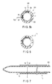
- FIG. 5a and FIG. 5b are cross sectional views showing a curve sensor 1b according to a second modification of the first embodiment.
- thin circular-tube-shaped elastic tubes 11 are fixed between the first elastic member 2 and the second elastic member 3 by an adhesive agent not shown.
- the light supply fibers 4a and 4b and the sensor fibers 6a and 6b are inserted through the elastic tubes 11.
- the parts of the sensor fibers 6a and 6b where the curved state detection unit 5 is provided are not covered with the elastic tubes 11.
- the inner diameter of the elastic tubes 11 is larger than the outer diameters of the light supply fibers 4a and 4b and the sensor fibers 6a and 6b. Therefore, the light supply fibers 4a and 4b and the sensor fibers 6a and 6b are slidable through the elastic tubes 11 in the optical axis direction (longitudinal direction) of the fibers.
- the elastic tubes 11 do not extend to both ends of the first elastic member 2. Therefore, the light supply fibers 4a and 4b and the sensor fibers 6a and 6b are fixed to the first and second elastic members 2 and 3 by, for example, an adhesive agent at both ends.
- the light supply fiber 4 and the sensor fiber 6 slide through the elastic tube 11 in the optical axis direction, the light supply fiber 4 and the sensor fiber 6 easily curve in accordance with the curving of the first and second elastic members 2 and 3. Therefore, the light supply fiber 4 and the sensor fiber 6 do not easily inhibit the curving of the whole curve sensor 1b.
- the curve sensor 1b can easily adapt to a larger curving angle.
- FIG. 6 is a cross sectional view showing a curve sensor 1c according to a third modification of the first embodiment.
- the cross sections of first and second elastic members 12 and 13 are not circular but are C-shaped. That is, a cutout 14 is formed in the circumferential walls of the first and second elastic members 12 and 13.
- the cutout 14 is formed in the first and second elastic members 12 and 13, so that the curve sensor 1c can be attached to a curving measurement target from the side.
- the curve sensor 1c is easily attached to the curving measurement target.
- the present modification is particularly suited to the case where the elastic members are metal spring members.
- the curved state detection unit 5 is disposed where the cutout 14 is not present, so that the curved state detection unit 5 is protected by the first and second elastic members 12 and 13 as the holding portions. Since the cutout 14 is formed, the rigidity of the first and second elastic members 12 and 13 is lower, and the curving is easier.
- the curve sensor 1c according to the present modification is suitably attached to a curving measurement target smaller in diameter than the endoscope, for example, a catheter which is inserted into a living tissue.
- FIG. 7 is a longitudinal sectional view schematically showing a catheter 101 to which the curve sensor 1c is attached.
- FIG. 8 is a cross sectional view taken along the line C-C in FIG. 7 .
- On the circumferential surface of the catheter 101 a through-hole 102 which radially pierces the outer circumferential surface is formed.
- the through-hole 102 is, for example, a discharge hole for a drug to administer the drug to the living tissue by using the catheter 101, or a suction hole to suck a body fluid or the like from the living tissue.
- the cutout 14 in the first and second elastic members 12 and 13 of the curve sensor 1c is aligned with the through-hole 102 of the catheter 101 so that the curve sensor 1c does not cover the through-hole 102 of the catheter 101, and the curve sensor 1c is then attached to the catheter 101.
- the curve sensor 1c is thus attached after the through-hole 102 of the catheter 101 is aligned with the cutout 14 of the curve sensor 1c. Consequently, the curve sensor 1c according to the present modification can be applied to the catheter 101 without inhibiting the function of the catheter 101.
- FIG. 9 is a diagram schematically showing a curve sensor 1d according to a fourth modification of the first embodiment.
- the cylindrical body 1A is separated into a distal side cylindrical body 15a and a proximal side cylindrical body 15b. That is, the cylindrical bodies as the holding members comprising elastic members are located apart from each other.
- the curved state detection unit 5 of the sensor fiber 6 is located in at least one of the distal side cylindrical body 15a and the proximal side cylindrical body 15b.
- the distal side cylindrical body 15a and the proximal side cylindrical body 15b are coupled to each other by the light supply fiber 4 and the sensor fiber 6 which are held and fixed by these cylindrical bodies.
- the elastic members as the holding portions are not provided in parts of the light supply fiber 4 and the sensor fiber 6, for example, in the part of the sensor fiber 6 where the curved state detection unit 5 is not provided, so that the rigidity of the part is lower. Therefore, the curving performance of the curve sensor can be improved by the reduced rigidity.
- the curved state detection unit is protected by the first and second elastic members as the holding portions.
- FIG. 10 and FIG. 11 are diagrams showing a curve sensor 20 according to the second embodiment.
- parts of the light supply fibers 4a and 4b according to the first embodiment are replaced with light supply paths 22a and 22b each including a core and a cladding provided on a flexible optical circuit board 21.
- At least parts of the sensor fibers 6a and 6b including the curved state detection units 5a and 5b according to the first embodiment are replaced with sensor paths 23a and 23b each including a core and a cladding provided on the flexible optical circuit board 21.
- the light supply paths 22a and 22b and the light supply fibers 4a and 4b, and the sensor paths 23a and 23b and the sensor fibers 6a and 6b are optically coupled to each other by, for example, fusion bonding.
- the first and second elastic members 2 and 3 according to the first embodiment are unnecessary.
- the flexible optical circuit board 21 functions as a holding portion which holds the curve detection mechanism including the curved state detection unit 5 at a predetermined position on the curving measurement target 100.
- the flexible optical circuit board 21 that is long enough (e.g. about 1 m long) to be adaptable to the endoscope in the longitudinal direction (optical axis direction) of the curve sensor 20.
- the sensor is manufactured by adding the light supply fibers 4a and 4b and the sensor fibers 6a and 6b as extension optical fibers to the flexible optical circuit board 21.
- the length of the curve sensor 20 can be extended to necessary length, which provides a configuration advantageous in respect of costs.
- the positional relation between the two curved state detection units 5a and 5b is determined by the accuracy of the space between the two sensor paths 23a and 23b of the flexible optical circuit board 21, so that it is not necessary to align the two sensor paths 23a and 23b during assembly. It is also unnecessary to adjust the positional relation between the two curved state detection units 5a and 5b in the circumferential direction of the curve sensor 20. Therefore, the assembly process of the curve sensor 20 can be simpler.
- the curved state detection unit is protected by the flexible optical circuit board.
- the flexible optical circuit board has the function to bundle the light supply paths and the sensor paths and the function to hold the light supply paths and the sensor paths to the flexible optical circuit board. Since the flexible optical circuit board has these two functions in one member, it is not necessary to increase the components of the curve sensor. Therefore, the rigidity of the curve sensor can be reduced, and the curve sensor easily curves.
- the core and the cladding are made of a resin, a curve sensor having higher curving performance is more easily provided.
- FIG. 12 is a cross sectional view of a curve sensor 20a according to a modification of the second embodiment.
- the flexible optical circuit board 21 is not limited to the type that uses the light supply paths and the sensor paths of the optical fiber including the core and the cladding.
- the flexible optical circuit board 21 is, for example, a flexible optical circuit board that uses light supply paths 24a and 24b comprising optical waveguide paths, and the sensor paths 25a and 25b comprising optical waveguide paths.
- the curved state detection units 5a and 5b are provided in the sensor paths 25a and 25b, which are respectively manufactured in advance in parts of the sensor paths 25a and 25b by, for example, printing during manufacture.
- the curve sensor having higher curving performance can be provided.
- the curved state detection unit is protected by the flexible optical circuit board.
- FIG. 13 is a diagram schematically showing a curve sensor 30 according to the third embodiment.
- the light supply fiber 4 and the sensor fiber 6 are formed by one optical fiber. Therefore, the curve sensor 30 does not have the reflecting member 7 according to the first embodiment, and a turnover 31 (31a and 31b) produced by folding one optical fiber along the way is formed. That is, the turnover 31 optically connects the light supply fiber 4 and the sensor fiber 6 without the reflecting member 7 in between.
- the curve sensor is not limited to the above, and may be configured by a flexible optical circuit board in which the turnover 31 is formed in advance.
- the reflecting member since the reflecting member is not provided, there is no reflection loss of the light guided by the optical fiber, and the curve sensor which is thus high in sensitivity can be provided. Since the configuration of the curve sensor can be simpler, the curve sensor is easily reduced in size and cost.
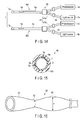
- FIG. 14 and FIG. 15 are diagrams showing a curve sensor 40 according to the fourth embodiment.
- the light supply fiber 4 and the sensor fiber 6 are connected to each other by an optical coupler 41 (41a and 41b), and the light supply fiber 4 and the sensor fiber 6 are combined into one optical fiber.
- the reflecting member 7 (7a and 7b) is disposed on the distal side of one sensor fiber 6 (6a and 6b).
- the light guided by the light supply fiber 4 is then guided by the sensor fiber 6 through the optical coupler 41, and the light reflected by the reflecting member 7 is further guided by the sensor fiber 6 and received by the photodetector 9 through the optical coupler 41.
- the photodetector 9 measures the light amount that is affected by the amount of the light which changes in the curved state detection unit 5 in accordance with the curving state of the sensor fiber 6.
- the light supply fiber and the sensor fiber are combined along the way, and at least part of the sensor fiber also serves as the light supply fiber, so that the number of fibers is reduced.
- the curve sensor is easily reduced in size. Since the number of fibers used is small, the curve sensor can be manufactured at low cost.
- the curved state detection unit is protected by the first and second elastic members as the holding portions.
- the rigidity of the light supply fiber does not easily prevent the curving of the curving measurement target. Moreover, the curve sensor adapted to a large curving angle is easily provided.
- FIG. 16 is a diagram schematically showing a second elastic member 51 of a curve sensor 50 according to the fifth embodiment.
- the second elastic member 51 of the curve sensor 50 has a first region 52 and a second region 53 that have different diameters.
- the first region 52 is formed by a small diameter portion having a small first diameter r.
- the second region 53 is formed by a large diameter portion having a second diameter R (r ⁇ R) larger than the first diameter r.
- the first region 52 is a region where the curved state detection unit 5 of the sensor fiber 6 is disposed.
- the second region 53 is a region where the curved state detection unit 5 is not disposed, that is, a region different from the region where the curved state detection unit 5 is disposed.
- the curving measurement target to be inserted into the second elastic member 51 is held by stronger elastic force in the first region 52 than in the second region 53. In the second region 53, the curving measurement target is held by weaker elastic force.
- the inner circumferential surface of the first elastic member which is engaged with the outer circumferential surface of the second elastic member 51 substantially adapts to the shape of a second outer circumferential surface, and is configured to hold and fix the curve detection mechanism including the light supply fiber, the sensor fiber, and others between the first and second elastic members.
- the region where the curved state detection unit is fixed to the curving measurement target by stronger elastic force is provided.
- a correct curving state can be measured, and at the same time, it is possible to easily adapt to a large curving angle.
- the optical fiber is held by weaker elastic force in the region where the curved state detection unit is not provided, so that the optical fiber is slidable in this region. Thus, curving is easy.
- FIG. 17 and FIG. 18 are diagrams showing a first elastic member 61 of a curve sensor 60 according to the sixth embodiment.
- at least one slit 63 is formed in the first elastic member 61 and the second elastic member to radially pierce the circumferential walls of these elastic members.
- the slits 63 are arranged at predetermined intervals in the circumferential direction of the first elastic member 61 and the second elastic member.
- the shape of the slit 63 is rectangular in FIG. 17 , but may be circular or elliptic.
- the second elastic member also has a similar configuration.
- the slits 63 are formed at positions different from the position of the curved state detection unit 5 in the longitudinal direction of the first elastic member 61 and the second elastic member.
- the slits 63 may be only provided in one of the first elastic member 61 and the second elastic member.
- the slits are formed at positions (positions where the curved state detection unit is not provided) different from the positions of the first and second elastic members where the curved state detection unit is located, so that the elastic members is reduced in rigidity, and the curving is easier.
- the curved state detection unit can be properly protected by the first and second elastic members.
- FIG. 19 is a diagram schematically showing one aspect of a curve sensor 70 according to the seventh embodiment.
- the curve sensor 70 includes an optical fiber 71 which connects the light supply fiber 4 and the light source 8, and an optical fiber 72 which connects the sensor fiber 6 and the photodetector 9.
- the optical fibers 71 and 72 are connected to a first driver 75 by optical connectors 73 and 74, respectively.
- the first driver 75 is further connected to a second driver 76 including the light source 8 and the photodetector 9.
- the curve sensor can be easily mounted on the curving measurement target. Since the curve sensor is attachable to and detachable from the curving measurement target by the connectors, the curved state detection unit can be easily cleaned.
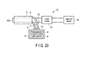
- FIG. 20 is a diagram schematically showing another aspect of the curve sensor 70 according to the seventh embodiment.
- the optical fiber 71 and the optical fiber 72 may be bundled by a binder 78 on the middle point of the fibers.
- the light source 8 and the photodetector 9 may be housed in a separate case 77.
- the optical fibers are easily handled by an operator.
- the light source and the photodetector do not need to be previously incorporated in the curving measurement target, and the curve sensor higher in versatility can be provided.
Landscapes
- Physics & Mathematics (AREA)
- Health & Medical Sciences (AREA)
- Life Sciences & Earth Sciences (AREA)
- Surgery (AREA)
- Optics & Photonics (AREA)
- General Physics & Mathematics (AREA)
- Medical Informatics (AREA)
- General Health & Medical Sciences (AREA)
- Pathology (AREA)
- Engineering & Computer Science (AREA)
- Biomedical Technology (AREA)
- Heart & Thoracic Surgery (AREA)
- Biophysics (AREA)
- Molecular Biology (AREA)
- Animal Behavior & Ethology (AREA)
- Veterinary Medicine (AREA)
- Public Health (AREA)
- Radiology & Medical Imaging (AREA)
- Nuclear Medicine, Radiotherapy & Molecular Imaging (AREA)
- Astronomy & Astrophysics (AREA)
- Dentistry (AREA)
- Oral & Maxillofacial Surgery (AREA)
- Endoscopes (AREA)
- Instruments For Viewing The Inside Of Hollow Bodies (AREA)
- Length Measuring Devices By Optical Means (AREA)
Applications Claiming Priority (2)
| Application Number | Priority Date | Filing Date | Title |
|---|---|---|---|
| JP2012138925A JP5963563B2 (ja) | 2012-06-20 | 2012-06-20 | 湾曲センサ |
| PCT/JP2013/066869 WO2013191214A1 (ja) | 2012-06-20 | 2013-06-19 | 湾曲センサ |
Publications (2)
| Publication Number | Publication Date |
|---|---|
| EP2865317A1 true EP2865317A1 (de) | 2015-04-29 |
| EP2865317A4 EP2865317A4 (de) | 2016-03-02 |
Family
ID=49768808
Family Applications (1)
| Application Number | Title | Priority Date | Filing Date |
|---|---|---|---|
| EP13807866.2A Withdrawn EP2865317A4 (de) | 2012-06-20 | 2013-06-19 | Kurvensensor |
Country Status (5)
| Country | Link |
|---|---|
| US (1) | US9766059B2 (de) |
| EP (1) | EP2865317A4 (de) |
| JP (1) | JP5963563B2 (de) |
| CN (1) | CN104334070B (de) |
| WO (1) | WO2013191214A1 (de) |
Families Citing this family (10)
| Publication number | Priority date | Publication date | Assignee | Title |
|---|---|---|---|---|
| TWI476554B (zh) * | 2013-03-22 | 2015-03-11 | Pegatron Corp | 監控系統 |
| US9645570B2 (en) * | 2013-03-22 | 2017-05-09 | Pegatron Corporation | Monitoring system |
| WO2016163030A1 (ja) * | 2015-04-10 | 2016-10-13 | オリンパス株式会社 | ファイバセンサ |
| CN107613834B (zh) * | 2015-05-29 | 2019-08-02 | 奥林巴斯株式会社 | 曲率传感器和搭载有该曲率传感器的内窥镜装置 |
| JP2018018720A (ja) * | 2016-07-28 | 2018-02-01 | パナソニックIpマネジメント株式会社 | 発光装置、および、発光装置の点検方法 |
| DE102018105132B4 (de) * | 2018-03-06 | 2023-07-13 | Haag-Streit Gmbh | Triangulationsvorrichtung |
| US11214120B2 (en) * | 2018-11-02 | 2022-01-04 | Continental Automotive Systems, Inc. | Distributed fiber optic sensing system |
| CN110095086B (zh) * | 2019-06-03 | 2024-06-07 | 呜啦啦(广州)科技有限公司 | 电流式双向弯曲传感器及其制备方法 |
| CN111678465B (zh) * | 2020-05-28 | 2021-12-10 | 哈尔滨工业大学 | 一种基于超声导波的管道弯曲检测方法 |
| US12228398B2 (en) * | 2022-03-24 | 2025-02-18 | The Aerospace Corporation | Non-contacting angular motion measuring device |
Family Cites Families (20)
| Publication number | Priority date | Publication date | Assignee | Title |
|---|---|---|---|---|
| JPH0591972A (ja) * | 1991-10-02 | 1993-04-16 | Toshiba Corp | 湾曲表示装置 |
| DE69406447T2 (de) * | 1993-06-10 | 1998-05-14 | Lee A Danisch | Faseroptischer biege- und positionierungssensor |
| JP4005318B2 (ja) | 2001-02-28 | 2007-11-07 | ペンタックス株式会社 | 可撓性内視鏡装置 |
| JP3881525B2 (ja) | 2001-05-22 | 2007-02-14 | ペンタックス株式会社 | 可撓性内視鏡装置 |
| JP3898910B2 (ja) | 2001-05-31 | 2007-03-28 | ペンタックス株式会社 | 可撓性内視鏡装置 |
| JP3881526B2 (ja) | 2001-05-22 | 2007-02-14 | ペンタックス株式会社 | 可撓性内視鏡装置 |
| WO2004056017A1 (en) * | 2002-12-16 | 2004-07-01 | Aston Photonic Technologies Limited | Optical interrogation system and sensor system |
| JP4383108B2 (ja) * | 2003-07-07 | 2009-12-16 | オリンパス株式会社 | 超音波診断装置 |
| DE102004017834B4 (de) * | 2004-04-13 | 2011-01-27 | Siemens Ag | Kathetereinrichtung |
| ATE433044T1 (de) * | 2004-08-27 | 2009-06-15 | Schlumberger Holdings | Sensor und vermessungsvorrichtung zur bestimmung des biegeradius und der form eines rohrleitungs |
| JP2007044405A (ja) * | 2005-08-12 | 2007-02-22 | Pentax Corp | 内視鏡挿入形状検出プローブ |
| JP2007044412A (ja) * | 2005-08-12 | 2007-02-22 | Pentax Corp | 内視鏡挿入形状検出プローブ |
| JP4714570B2 (ja) * | 2005-11-24 | 2011-06-29 | Hoya株式会社 | 内視鏡形状検出プローブ |
| US8989528B2 (en) * | 2006-02-22 | 2015-03-24 | Hansen Medical, Inc. | Optical fiber grating sensors and methods of manufacture |
| GB0620944D0 (en) * | 2006-10-20 | 2006-11-29 | Insensys Ltd | Curvature measurement moving relative to pipe |
| JP4580973B2 (ja) * | 2007-11-29 | 2010-11-17 | オリンパスメディカルシステムズ株式会社 | 処置具システム |
| US8886334B2 (en) * | 2008-10-07 | 2014-11-11 | Mc10, Inc. | Systems, methods, and devices using stretchable or flexible electronics for medical applications |
| EP2351509A4 (de) * | 2008-10-28 | 2018-01-17 | Olympus Corporation | Medizinische vorrichtung |
| US9387048B2 (en) * | 2011-10-14 | 2016-07-12 | Intuitive Surgical Operations, Inc. | Catheter sensor systems |
| US9062960B2 (en) * | 2012-02-07 | 2015-06-23 | Medlumics S.L. | Flexible waveguides for optical coherence tomography |
-
2012
- 2012-06-20 JP JP2012138925A patent/JP5963563B2/ja not_active Expired - Fee Related
-
2013
- 2013-06-19 EP EP13807866.2A patent/EP2865317A4/de not_active Withdrawn
- 2013-06-19 CN CN201380027015.0A patent/CN104334070B/zh not_active Expired - Fee Related
- 2013-06-19 WO PCT/JP2013/066869 patent/WO2013191214A1/ja not_active Ceased
-
2014
- 2014-12-15 US US14/570,176 patent/US9766059B2/en not_active Expired - Fee Related
Also Published As
| Publication number | Publication date |
|---|---|
| US20150100000A1 (en) | 2015-04-09 |
| WO2013191214A1 (ja) | 2013-12-27 |
| JP5963563B2 (ja) | 2016-08-03 |
| US9766059B2 (en) | 2017-09-19 |
| CN104334070B (zh) | 2017-03-15 |
| JP2014000312A (ja) | 2014-01-09 |
| CN104334070A (zh) | 2015-02-04 |
| EP2865317A4 (de) | 2016-03-02 |
Similar Documents
| Publication | Publication Date | Title |
|---|---|---|
| US9766059B2 (en) | Curve sensor | |
| CN219846780U (zh) | 医疗设备和医疗设备系统 | |
| JP5139298B2 (ja) | 接続装置および補助装置ならびにアダプタ固定部材 | |
| JP6270347B2 (ja) | 形状センサ | |
| CN106231979B (zh) | 内窥镜装置 | |
| EP2128566A3 (de) | Verlässlicher Hohlkern-Faserresonator mit geringem Verlust | |
| US10436578B2 (en) | Endoscope apparatus | |
| US20170105626A1 (en) | Optical fiber cable, method of manufacturing the same, and light source module including the same | |
| CN105263386A (zh) | 用于光学相干断层扫描的导管以及导管制造方法 | |
| CN105451630B (zh) | 插入系统以及对形状传感器的形状检测特性进行调整的方法 | |
| JP5296867B2 (ja) | 光伝送装置 | |
| EP2954831A1 (de) | Biegevorrichtung | |
| US20110301413A1 (en) | Ultrasonic endoscope | |
| JP2017074254A (ja) | 内視鏡 | |
| US10302933B2 (en) | Insertion apparatus | |
| EP3195792A1 (de) | Optische sendereinheit, verfahren zum verbinden eines optischen sendermoduls und übertragungsseitiger optischer stecker und endoskopsystem | |
| JP2007044412A (ja) | 内視鏡挿入形状検出プローブ | |
| EP3949887B1 (de) | Glasfaserzustandserkennungssystem | |
| JPWO2017009906A1 (ja) | 形状検出装置 | |
| CN116327129B (zh) | 一种光纤探头及共聚焦显微成像系统 | |
| EP2455791A2 (de) | Optischer Faseradapter und Lasersystem | |
| US20210132299A1 (en) | Cleaning tool and adhesive body | |
| CN211912437U (zh) | 具有液态压力检测功能的腔道引导组件 | |
| JP2016085158A (ja) | 計測装置、それを用いた医療機器および訓練用シミュレータ | |
| KR20180012079A (ko) | 거리 확장과 온도 보상이 가능한 휴대용 광섬유 센서 시스템 |
Legal Events
| Date | Code | Title | Description |
|---|---|---|---|
| PUAI | Public reference made under article 153(3) epc to a published international application that has entered the european phase |
Free format text: ORIGINAL CODE: 0009012 |
|
| 17P | Request for examination filed |
Effective date: 20141219 |
|
| AK | Designated contracting states |
Kind code of ref document: A1 Designated state(s): AL AT BE BG CH CY CZ DE DK EE ES FI FR GB GR HR HU IE IS IT LI LT LU LV MC MK MT NL NO PL PT RO RS SE SI SK SM TR |
|
| AX | Request for extension of the european patent |
Extension state: BA ME |
|
| DAX | Request for extension of the european patent (deleted) | ||
| RA4 | Supplementary search report drawn up and despatched (corrected) |
Effective date: 20160128 |
|
| RIC1 | Information provided on ipc code assigned before grant |
Ipc: A61B 1/00 20060101AFI20160122BHEP |
|
| RAP1 | Party data changed (applicant data changed or rights of an application transferred) |
Owner name: OLYMPUS CORPORATION |
|
| GRAP | Despatch of communication of intention to grant a patent |
Free format text: ORIGINAL CODE: EPIDOSNIGR1 |
|
| INTG | Intention to grant announced |
Effective date: 20170908 |
|
| STAA | Information on the status of an ep patent application or granted ep patent |
Free format text: STATUS: THE APPLICATION IS DEEMED TO BE WITHDRAWN |
|
| 18D | Application deemed to be withdrawn |
Effective date: 20180119 |