EP2865329A1 - Plages de localisation autonome connectées en série - Google Patents
Plages de localisation autonome connectées en série Download PDFInfo
- Publication number
- EP2865329A1 EP2865329A1 EP20140190346 EP14190346A EP2865329A1 EP 2865329 A1 EP2865329 A1 EP 2865329A1 EP 20140190346 EP20140190346 EP 20140190346 EP 14190346 A EP14190346 A EP 14190346A EP 2865329 A1 EP2865329 A1 EP 2865329A1
- Authority
- EP
- European Patent Office
- Prior art keywords
- location
- electrical power
- coils
- bus
- radiator coils
- Prior art date
- Legal status (The legal status is an assumption and is not a legal conclusion. Google has not performed a legal analysis and makes no representation as to the accuracy of the status listed.)
- Granted
Links
Images



Classifications
-
- A—HUMAN NECESSITIES
- A61—MEDICAL OR VETERINARY SCIENCE; HYGIENE
- A61B—DIAGNOSIS; SURGERY; IDENTIFICATION
- A61B5/00—Measuring for diagnostic purposes; Identification of persons
- A61B5/06—Devices, other than using radiation, for detecting or locating foreign bodies ; Determining position of diagnostic devices within or on the body of the patient
- A61B5/061—Determining position of a probe within the body employing means separate from the probe, e.g. sensing internal probe position employing impedance electrodes on the surface of the body
- A61B5/062—Determining position of a probe within the body employing means separate from the probe, e.g. sensing internal probe position employing impedance electrodes on the surface of the body using magnetic field
-
- G—PHYSICS
- G01—MEASURING; TESTING
- G01B—MEASURING LENGTH, THICKNESS OR SIMILAR LINEAR DIMENSIONS; MEASURING ANGLES; MEASURING AREAS; MEASURING IRREGULARITIES OF SURFACES OR CONTOURS
- G01B7/00—Measuring arrangements characterised by the use of electric or magnetic techniques
- G01B7/004—Measuring arrangements characterised by the use of electric or magnetic techniques for measuring coordinates of points
Definitions
- the present invention relates generally to medical imaging, and specifically to using serially connected location pads to track a location of an object inserted into a body cavity of a patient.
- Magnetic position sensing is one of the methods known in the art. In magnetic position sensing, magnetic field generators are typically placed at known positions external to the patient. A magnetic field sensor within the distal end of a probe generates electrical signals in response to these magnetic fields, which are processed in order to determine the position coordinates of the distal end of the probe.
- an apparatus for tracking an object including, a bus including electrical power and data lines, a plurality of location pads, which are positionable at different, respective locations with respect to a body cavity in which the object is located, and which are connected to the bus in series so as to receive electrical power and exchange data signals over the bus, each location pad including multiple radiator coils, and driving circuitry, which is configured, responsively to the data signals, to select different respective driving frequencies for the radiator coils in the location pad and to generate, using the electrical power from the bus, driving signals to drive the coils to produce magnetic fields at the respective driving frequencies, and a console, which is configured to receive and process sensor signals from a magnetic sensor fixed to the object, in response to the magnetic fields in the body cavity, in order to compute position coordinates of the object.
- the body cavity may include a chamber of a heart, and the object may include an intracardiac catheter.
- first given radiator coils on a first given location pad may have a first operating volume
- second given radiator coils on a second given location pad adjacent to the first given location pad may have a second operating volume
- the second operating volume may overlap the first operating volume.
- the respective driving frequencies of the first given radiator coils may differ from the respective driving frequencies of the second given radiator coils.
- the multiple radiator coils may include three sets of three radiator coils, and the three radiator coils can be arranged in an orthogonal configuration.
- a given driving circuitry can be configured to switch the electrical power to its respective radiator coils in response to computing a location corresponding to the position coordinates, the respective radiator coils having an operating volume.
- the given driving circuitry can be configured to switch the electrical power to its respective radiator coils in response to computing a location corresponding to the position coordinates
- the given driving circuitry can be configured to switch the electrical power by conveying the electrical power from the bus to its respective radiator coils upon the operating volume including the location.
- the given driving circuitry can be configured to switch the electrical power to its respective radiator coils in response to computing a location corresponding to the position coordinates
- the given driving circuitry can be configured to switch the electrical power by switching off the electrical power to the respective radiator coils upon the respective operating volume not including the location.
- switching off the electrical power can be selected from a list including reducing the electrical power conveyed from the serial bus to the respective radiator coils, and ceasing to convey the electrical power from the serial bus to the respective radiator coils.
- a method for tracking an object including positioning a plurality of location pads at different, respective locations with respect to a body cavity, the location pads being connected in series to a bus so as to receive electrical power and exchange data signals over the bus, each location pad having respective driving circuitry and respective multiple radiator coils, selecting, by the driving circuitry on each of the location pads, different respective driving frequencies for the respective radiator coils in response to the data signals, using, by the driving circuitry on each of the location pads, the electrical power from the bus to generate driving signals to drive the respective radiator coils to produce magnetic fields at the respective driving frequencies, and upon inserting the object into the body cavity, receiving, by a console processor, signals from a magnetic sensor fixed to the object in response to the magnetic fields in the body cavity, and processing the received signals to compute position coordinates of the object.
- a computer software product operated in conjunction with a plurality of location pads positioned at different, respective locations with respect to a body cavity of a patient, the location pads being connected to a bus in series so as to receive electrical power and exchange data signals over the bus, each location pad having respective driving circuitry and respective multiple radiator coils, and an object that is configured for insertion into the body cavity and includes a magnetic sensor for measuring a location of a distal end of the object, the product including a first non-transitory computer-readable medium, in which first program instructions are stored, which instructions, when read by the driving circuitry on each of the location pads, cause the driving circuitry on each of the location pads to select different respective driving frequencies for the respective radiator coils in response to the data signals, and to generate, using the electrical power from the bus, driving signals to drive the coils to produce magnetic fields at the respective driving frequencies, and a second non-transitory computer-readable medium, in which second program instructions are stored, which instructions, when read by a
- Embodiments of the present invention provide methods and systems for tracking an object (e.g., an intracardiac catheter) inserted into a body cavity (e.g., a chamber of a heart) of a patient during a medical procedure.
- an object e.g., an intracardiac catheter
- a body cavity e.g., a chamber of a heart
- a plurality of location pads having respective driving circuitry and respective multiple coils can be connected in series to a bus so as to receive electrical power and exchange data signals over the bus, and be positioned at different respective locations with respect to the body cavity.
- a given location pad's respective driving circuitry in response to the data signals received via the bus, can be configured to select different respective driving frequencies for its respective radiator coils, and to use the electrical power from the bus to generate driving signals to drive the respective radiator coils pad to produce magnetic fields at the respective driving frequencies.
- a console coupled to the bus can receive, from a magnetic sensor fixed to the object, signals in response to the magnetic fields in the body cavity, and process the received signals to compute position coordinates that include a location of the object.
- a given pad's driving circuitry can be configured to switch the electrical power to its respective radiator coils in response to the computed location.
- the given location pad's driving circuitry can convey the electrical power from the bus to the respective radiator coils upon the operating volume including the computed location, and can switch off (or reduce) the electrical power to the respective radiator coils upon the respective operating volume not including the computed location, thereby reducing power consumption.
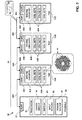
- FIG. 1 is a schematic, pictorial illustration of medical system 20 that comprises a control console 22 and multiple location pads 24, and Figure 2 is a block diagram of the console and the location pads, in accordance with an embodiment of the present invention.
- System 20 comprises a probe 26, such as an intracardiac catheter that is used for diagnostic or therapeutic treatment, such as for mapping electrical potentials in a heart 28 of a patient 30.
- probe 26 may be used, mutatis mutandis, for other therapeutic and/or diagnostic purposes in the heart or in other body organs.
- Console 22 typically uses magnetic position sensing to determine position coordinates of distal end 34 inside heart 28. To determine the position coordinates, a driver circuit 36 in console 22 drives location pads 24 to generate magnetic fields within the body of patient 30.
- location pads 24 are placed below the patient's torso at known locations external to patient 30, and may be differentiated by appending a letter to the identifying numeral, so that the location pads comprise location pads 24A, 24B and 24C.
- Location pads 24 comprise two pad ports 38, pad driver circuitry 40 and multiple coils sets 42.
- each pad 24 comprises three coil sets 42, and each of the coil sets comprises three radiator coils 44 arranged in an orthogonal configuration, thereby totaling nine radiator coils 44 on each pad 24.
- a serial bus 46 conveys electrical power (also referred to herein as power) received from a power source 48 in console 22, and conveys data signals between console 22 and location pads 24.
- serial bus 46 comprises multiple serial connections 50, with each of the serial connections typically comprising a cable comprising one or more data lines 66 configured to convey data signals and one or more power lines 68 configured to convey electrical power.
- Serial connections 50 may be differentiated by appending a letter to the identifying numeral, so that the serial connections comprise a serial connection 50A that couples console 22 and pad 24A, a serial connection 50B that couples pad 24A and pad 24B, and a serial connection 50C that couples pad 24B and pad 24C.
- Console 22 comprises a console port 52 that enables the console to interact with probe 26, to convey the electrical power from power source 48 to serial bus 46, and to communicate with the location pads.
- console port 52 conveys the electrical power from power source 48 to pads 24 via serial connections 50A, 50B and 50C.
- a given pad 24 receives the electrical power from a first serial connection 50 via a first pad port 38, uses some of the electrical power to power components on the given pad, and conveys the remaining electrical power to a second serial connection 50 via a second pad port 38.
- Pads 24 communicate with each other and console 22 in a similar manner, except that data signals can be conveyed in two directions (as opposed to the electrical power that is conveyed in a single direction). For example, when console 22 sends a first data signal to pad 24B, the signal is conveyed via serial connections 50A and 50B, and pad 24B can send a second data signal to the console via serial connections 50B and 50A.
- each pad 24 can be configured, using its respective driving circuitry 40, to operate autonomously. As explained hereinbelow, each pad can select each of the nine frequencies at which its respective coils radiate electromagnetic fields, and switch electrical power (received from console 22 via the serial connection) on and off to these coils.
- Coil sets 42 generate magnetic fields in a predefined working volume that contains heart 28.
- a magnetic field sensor 54 also referred to herein as magnetic sensor 54
- a console processor 56 processes these signals in order to determine the position coordinates of a distal tip 58 of probe 26, typically including both location and orientation coordinates.
- the method of position sensing described hereinabove is implemented in the CARTOTM system produced by Biosense Webster of Diamond Bar, CA, and is described in detail in the patents and patent applications cited above.
- Magnetic sensor 54 transmits a signal to console 22 that is indicative of the position coordinates of distal tip 58.
- Magnetic sensor 54 may comprise one or more probe coils (not shown), and typically comprises multiple probe coils oriented along different axes. Typically, sensor 54 comprises three probe coils arranged orthogonally.
- Figure 1 shows a probe with a single magnetic sensor, embodiments of the present invention may utilize probes with more than one magnetic sensor. Magnetic position tracking techniques are described, for example, in U.S. Patents 5,443,489 , 6,788,967 , 6,690,963 , 5,558,091 , 6,172,499 , and 6,177,792 , whose disclosures are incorporated herein by reference.
- processor 56 drives a display 60 to present operator 32 with an image 62 showing the location of distal end 34 in the patient's body, as well as status information and guidance regarding the procedure that is in progress.
- operator 32 can manipulate image 62 using one or more input devices 64.
- Driving circuitries 40 and processor 56 typically comprise general-purpose computers, with suitable front end and interface circuits for receiving signals from probe 26 and controlling the other components of console 22.
- Driving circuitries 40 and processor 56 may be programmed in software to carry out the functions that are described herein.
- the software may be downloaded to console 22 and location pads 24 in electronic form, over a network, for example, or it may be provided on non-transitory tangible media, such as optical, magnetic or electronic memory media.
- some or all of the functions of driving circuitries 40 and processor 56 may be carried out by dedicated or programmable digital hardware components.
- FIG. 3 is a schematic pictorial illustration of pads 24 positioned under patient 30 during a medical procedure, in accordance with an embodiment of the present invention.
- each pad 24 has a relatively small corresponding operating volume 70 within which processor 56 can track objects such as distal end 34 of probe 22.
- Operating volumes 70 may be differentiated by appending a letter to the identifying numeral, so that the operating volumes comprise operating volumes 70A, 70B and 70C.
- operating volume 70A comprises the corresponding operating volume for location pad 24A
- operating volume 70B comprises the corresponding operating volume for location pad 24B
- operating volume 70C comprises the corresponding operating volume for location pad 24C.
- the location pads can be fixedly mounted on a board 72 so that operating volumes 70A, 70B and 70C overlap in order to create a contiguous operating volume 70 where processor 56 can track locations of distal tip 58 as operator 32 maneuvers probe 26 during a medical procedure. While the configuration in Figures 1-3 figure show three pads 24A, 24B and 24C having respective operating volumes 70A, 70B and 70C, any number of location pads 24 (and corresponding operating volumes 70) coupled via serial bus 46 are considered to be within the spirit and scope of the present invention.
- the driving circuitries of the first and the second location pads can be configured to select the respective driving frequencies so that the driving frequencies of the coils on the first location pad are different from the driving frequencies of the second location pad, thereby enabling processor 56 to accurately detect locations of distal tip 58 as the operator maneuvers the distal tip between the first and the second operating volumes.
- FIG. 4 is a flow diagram that schematically illustrates a method of managing location pads 24, in accordance with an embodiment of the present invention.
- console processor 56 conveys a configuration message to each driving circuitry 40 in system 20, and upon receiving the configuration message, each of the driving circuitries assigns respective operating frequencies to its respective coils 44.
- the given pad's driving circuitry 40 assigns a distinct frequency to each of the given pad's nine coils 44 (each pad 24 comprises three coil sets 42 that comprise three coils 44). Additionally, as described supra, in configurations comprising overlapping volumes 70, a given driving circuitry 40 of a given pad 24 can communicate with any adjacent pads 24 having overlapping volumes 70 in order to configure coils 44 so that each coil on the given pad and the adjacent pad(s) transmits at a distinct frequency.
- driving circuitry 40B communicates with driving circuitries 40A and 40C to ensure that each coil 44 on location pads 24A, 24B and 24C transmits at distinct frequencies.
- Figure 3 presents the frequency distribution as a Venn diagram, wherein operating volume 70A indicates a first set of nine frequencies used by coils 44A, operating volume 70B indicates a second set of nine distinct frequencies used by coils 44B, and operating volume 70C indicates a third set of nine distinct frequencies used by coils 44C. Since the second set of nine frequencies has a first intersection with the first set of nine frequencies and a second intersection with the third set of nine frequencies, driving circuitries 40A, 40B and 40C need to select a distinct frequency for each of the 27 coils on the three location pads in system 20.
- processor 56 conveys a pad activation message to one or more driving circuitries 40 to switch on all coils 44 on the one or more location pads.
- system 20 is configured to switch power on and off to respective coils 44 of a given pad 24 based on a current location of distal tip 58.
- an active pad 24 comprises a given location pad presently conveying full power to its respective coils 44 in order to generate magnetic fields
- an inactive pad 24 comprises a given location pad that is presently not conveying any power to its respective coils 44 (or is presently conveying reduced power to its respective coils). Therefore, at any time during a medical procedure using probe 26, each pad 24 is either active or inactive.
- processor 56 can send the pad activation messages to all driving circuitries 40, and all the processors can fully power coils 44 from electrical power carried on serial bus 46.
- operator 32 can select, using input devices 64, a given pad 24 whose respective operating volume 70 includes a location of distal tip 58 at the beginning of a medical procedure. Upon detecting the selection, processor 56 can convey a pad activation message to the respective driving circuitry 40 of the given pad, and upon receiving the power initialization message, the respective driving circuitry can fully power the coils on the given pad.
- system 20 may use the fixed positioning of pads 24 on board 72 to register and delineate volumes 70.
- sensor 54 may be moved to known locations with respect to board 72, and signals from the sensor may be used to register and delineate the volumes.
- processor 56 receives measurements from magnetic sensor 54 indicating a location of distal tip 58 in patient 30.
- the measurements include values of the respective frequencies of coils whose operating volume 70 includes the location of distal tip 58.
- a first comparison step 86 if there are any inactive location pads 24 whose respective operating volumes 70 include the location of distal tip 58, then in a first power switch step 88, the inactive location pads identified in step 86 switch on power to their respective coils sets 42, thereby activating the pads identified in step 86. When power is switched on, sufficient electrical power is conveyed from the serial bus to the coils so that the coils can radiate their respective magnetic fields.
- pad 24A is active
- pads 24B and 24C are inactive
- distal tip 58 is in a first location that is exclusively in volume 70A.
- driving circuitry 40B conveys power from serial connection 50B to coils sets 42B.
- processor 56 upon processor 56 identifying distal tip 58 moving from the first location to the second location, processor 56 can send a pad activation message to driving circuitry 40B, and driving circuitry 40B conveys power to coil sets 42B responsively to the pad activation message.
- processor 56 conveys real-time locations of distal tip 58 to driving circuitries 40
- driving circuitry 40B conveys power to coil sets 42B upon receiving the second location and identifying that the received second location is within its respective operating volume 70.
- a second comparison step 90 if there are any active location pads 24 whose respective operating volumes 70 do not include the location of distal tip 58, then in a second power switch step 92, the active location pads identified in step 90 switch off power to their respective coil sets 42 thereby inactivating the pads identified in step 90, and the method continues with step 84.
- switching off the power may comprise either reducing the power conveyed from serial bus 46 (serial connection 50B in the present example) to coils 44B or ceasing all power to coils 44B.
- pads 24A and 24B are active, pad 24C is inactive, and distal tip 58 is located at the second location.
- driving circuitry 40A switches off the power to the coils in coil sets 42B.
- the console processor can send a pad deactivation message to driving circuitry 40A, and in response to the pad deactivation message, processor 40A deactivates coil sets 42A by switching of the coils in coil sets 42A, thereby placing coil sets 42A in a "standby" mode.
- processor 56 conveys real-time locations of distal tip 58 to driving circuitries 40, and driving circuitry 40A deactivates coil sets 42B upon receiving the third location and identifying that the received third location is not within its respective operating volume 70.
- step 90 if there are no active location pads 24 whose respective operating volumes 70 do not include the location of distal tip 58, then the method continues with step 84.
- step 86 if there are no inactive location pads 24 whose respective operating volumes 70 include the location of distal tip 58, then the method continues with step 90.
Landscapes
- Life Sciences & Earth Sciences (AREA)
- Health & Medical Sciences (AREA)
- Engineering & Computer Science (AREA)
- Physics & Mathematics (AREA)
- Molecular Biology (AREA)
- Surgery (AREA)
- Pathology (AREA)
- Biomedical Technology (AREA)
- Heart & Thoracic Surgery (AREA)
- Medical Informatics (AREA)
- Human Computer Interaction (AREA)
- Biophysics (AREA)
- Animal Behavior & Ethology (AREA)
- General Health & Medical Sciences (AREA)
- Public Health (AREA)
- Veterinary Medicine (AREA)
- General Physics & Mathematics (AREA)
- Media Introduction/Drainage Providing Device (AREA)
- Surgical Instruments (AREA)
- Endoscopes (AREA)
Applications Claiming Priority (1)
| Application Number | Priority Date | Filing Date | Title |
|---|---|---|---|
| US14/063,418 US9241656B2 (en) | 2013-10-25 | 2013-10-25 | Serially connected autonomous location pads |
Publications (2)
| Publication Number | Publication Date |
|---|---|
| EP2865329A1 true EP2865329A1 (fr) | 2015-04-29 |
| EP2865329B1 EP2865329B1 (fr) | 2016-06-01 |
Family
ID=51870823
Family Applications (1)
| Application Number | Title | Priority Date | Filing Date |
|---|---|---|---|
| EP14190346.8A Active EP2865329B1 (fr) | 2013-10-25 | 2014-10-24 | Plages de localisation autonome connectées en série |
Country Status (7)
| Country | Link |
|---|---|
| US (1) | US9241656B2 (fr) |
| EP (1) | EP2865329B1 (fr) |
| JP (1) | JP6433753B2 (fr) |
| CN (1) | CN104545921B (fr) |
| AU (1) | AU2014248538B2 (fr) |
| CA (1) | CA2865340A1 (fr) |
| IL (1) | IL234653A (fr) |
Families Citing this family (7)
| Publication number | Priority date | Publication date | Assignee | Title |
|---|---|---|---|---|
| USD748137S1 (en) * | 2013-08-20 | 2016-01-26 | Biosense Webster (Israel) Ltd. | Portion of a computer screen with an icon |
| US10932861B2 (en) * | 2016-01-14 | 2021-03-02 | Auris Health, Inc. | Electromagnetic tracking surgical system and method of controlling the same |
| US10404093B2 (en) | 2017-04-26 | 2019-09-03 | Biosense Webster (Israel) Ltd. | Using location transmission signals for charging a wireless medical tool of an electromagnetic navigation system |
| US10874462B2 (en) | 2017-06-30 | 2020-12-29 | Biosense Webster (Israel) Ltd. | Network sniffer for system watchdog and diagnostic |
| WO2020010063A1 (fr) * | 2018-07-02 | 2020-01-09 | Boston Scientific Scimed Inc | Émetteur sonore magnétique |
| WO2020061504A1 (fr) * | 2018-09-22 | 2020-03-26 | Radwave Technologies Inc. | Matrice de nacelle d'antenne |
| CA3093980C (fr) * | 2019-09-26 | 2023-10-31 | Ascension Technology Corporation | Reseau de transmetteurs reconfigurables pour des systemes de suivi electromagnetiques |
Citations (14)
| Publication number | Priority date | Publication date | Assignee | Title |
|---|---|---|---|---|
| US5211165A (en) * | 1991-09-03 | 1993-05-18 | General Electric Company | Tracking system to follow the position and orientation of a device with radiofrequency field gradients |
| US5391199A (en) | 1993-07-20 | 1995-02-21 | Biosense, Inc. | Apparatus and method for treating cardiac arrhythmias |
| WO1996005768A1 (fr) | 1994-08-19 | 1996-02-29 | Biosense, Inc. | Systemes medicaux de diagnostic, de traitement et d'imagerie |
| US5558091A (en) | 1993-10-06 | 1996-09-24 | Biosense, Inc. | Magnetic determination of position and orientation |
| US6172499B1 (en) | 1999-10-29 | 2001-01-09 | Ascension Technology Corporation | Eddy current error-reduced AC magnetic position measurement system |
| US6177792B1 (en) | 1996-03-26 | 2001-01-23 | Bisense, Inc. | Mutual induction correction for radiator coils of an objects tracking system |
| US6239724B1 (en) | 1997-12-30 | 2001-05-29 | Remon Medical Technologies, Ltd. | System and method for telemetrically providing intrabody spatial position |
| US6332089B1 (en) | 1996-02-15 | 2001-12-18 | Biosense, Inc. | Medical procedures and apparatus using intrabody probes |
| EP1202077A2 (fr) * | 2000-10-31 | 2002-05-02 | Biosense, Inc. | Suppression de diaphonie mutuelle pour sytèmes médicaux |
| US20020065455A1 (en) | 1995-01-24 | 2002-05-30 | Shlomo Ben-Haim | Medical diagnosis, treatment and imaging systems |
| US6484118B1 (en) | 2000-07-20 | 2002-11-19 | Biosense, Inc. | Electromagnetic position single axis system |
| US20030120150A1 (en) | 2001-12-21 | 2003-06-26 | Assaf Govari | Wireless position sensor |
| US6618612B1 (en) | 1996-02-15 | 2003-09-09 | Biosense, Inc. | Independently positionable transducers for location system |
| US20040068178A1 (en) | 2002-09-17 | 2004-04-08 | Assaf Govari | High-gradient recursive locating system |
Family Cites Families (5)
| Publication number | Priority date | Publication date | Assignee | Title |
|---|---|---|---|---|
| JP3432825B2 (ja) * | 1992-08-14 | 2003-08-04 | ブリテイッシュ・テレコミュニケーションズ・パブリック・リミテッド・カンパニー | 位置決定システム |
| US6288785B1 (en) | 1999-10-28 | 2001-09-11 | Northern Digital, Inc. | System for determining spatial position and/or orientation of one or more objects |
| US20010045826A1 (en) | 2000-03-16 | 2001-11-29 | Schneider Mark R. | Distortion immune magnetic field generator for magnetic tracking systems and method of generating magnetic fields |
| US20060241397A1 (en) | 2005-02-22 | 2006-10-26 | Assaf Govari | Reference pad for position sensing |
| DE102011013398A1 (de) | 2010-03-10 | 2011-09-15 | Northern Digital Inc. | Magnetisches Ortungssystem |
-
2013
- 2013-10-25 US US14/063,418 patent/US9241656B2/en active Active
-
2014
- 2014-09-15 IL IL234653A patent/IL234653A/en active IP Right Grant
- 2014-09-26 CA CA 2865340 patent/CA2865340A1/fr not_active Abandoned
- 2014-10-14 AU AU2014248538A patent/AU2014248538B2/en not_active Ceased
- 2014-10-24 CN CN201410578400.0A patent/CN104545921B/zh active Active
- 2014-10-24 JP JP2014217022A patent/JP6433753B2/ja active Active
- 2014-10-24 EP EP14190346.8A patent/EP2865329B1/fr active Active
Patent Citations (18)
| Publication number | Priority date | Publication date | Assignee | Title |
|---|---|---|---|---|
| US5211165A (en) * | 1991-09-03 | 1993-05-18 | General Electric Company | Tracking system to follow the position and orientation of a device with radiofrequency field gradients |
| US5391199A (en) | 1993-07-20 | 1995-02-21 | Biosense, Inc. | Apparatus and method for treating cardiac arrhythmias |
| US5443489A (en) | 1993-07-20 | 1995-08-22 | Biosense, Inc. | Apparatus and method for ablation |
| US5558091A (en) | 1993-10-06 | 1996-09-24 | Biosense, Inc. | Magnetic determination of position and orientation |
| WO1996005768A1 (fr) | 1994-08-19 | 1996-02-29 | Biosense, Inc. | Systemes medicaux de diagnostic, de traitement et d'imagerie |
| EP0894473A2 (fr) * | 1994-08-19 | 1999-02-03 | Biosense, Inc. | Systemes medicaux de diagnostic, de traitement et d'imagerie |
| US6690963B2 (en) | 1995-01-24 | 2004-02-10 | Biosense, Inc. | System for determining the location and orientation of an invasive medical instrument |
| US20020065455A1 (en) | 1995-01-24 | 2002-05-30 | Shlomo Ben-Haim | Medical diagnosis, treatment and imaging systems |
| US6618612B1 (en) | 1996-02-15 | 2003-09-09 | Biosense, Inc. | Independently positionable transducers for location system |
| US6332089B1 (en) | 1996-02-15 | 2001-12-18 | Biosense, Inc. | Medical procedures and apparatus using intrabody probes |
| US6177792B1 (en) | 1996-03-26 | 2001-01-23 | Bisense, Inc. | Mutual induction correction for radiator coils of an objects tracking system |
| US6788967B2 (en) | 1997-05-14 | 2004-09-07 | Biosense, Inc. | Medical diagnosis, treatment and imaging systems |
| US6239724B1 (en) | 1997-12-30 | 2001-05-29 | Remon Medical Technologies, Ltd. | System and method for telemetrically providing intrabody spatial position |
| US6172499B1 (en) | 1999-10-29 | 2001-01-09 | Ascension Technology Corporation | Eddy current error-reduced AC magnetic position measurement system |
| US6484118B1 (en) | 2000-07-20 | 2002-11-19 | Biosense, Inc. | Electromagnetic position single axis system |
| EP1202077A2 (fr) * | 2000-10-31 | 2002-05-02 | Biosense, Inc. | Suppression de diaphonie mutuelle pour sytèmes médicaux |
| US20030120150A1 (en) | 2001-12-21 | 2003-06-26 | Assaf Govari | Wireless position sensor |
| US20040068178A1 (en) | 2002-09-17 | 2004-04-08 | Assaf Govari | High-gradient recursive locating system |
Also Published As
| Publication number | Publication date |
|---|---|
| CN104545921A (zh) | 2015-04-29 |
| EP2865329B1 (fr) | 2016-06-01 |
| CN104545921B (zh) | 2019-07-09 |
| AU2014248538A1 (en) | 2015-05-14 |
| US20150119686A1 (en) | 2015-04-30 |
| IL234653A (en) | 2017-12-31 |
| AU2014248538B2 (en) | 2018-09-27 |
| US9241656B2 (en) | 2016-01-26 |
| JP6433753B2 (ja) | 2018-12-05 |
| JP2015083131A (ja) | 2015-04-30 |
| CA2865340A1 (fr) | 2015-04-25 |
Similar Documents
| Publication | Publication Date | Title |
|---|---|---|
| EP2865329B1 (fr) | Plages de localisation autonome connectées en série | |
| US12588952B2 (en) | Flexible multi-coil tracking sensor | |
| EP3551117B1 (fr) | Mise à l'échelle du déplacement guidé par imagerie pour commande de robot | |
| EP3395282B1 (fr) | Vue endoscopique des procédures invasives dans les passages étroits | |
| US10898273B2 (en) | Insertion device positioning guidance system and method | |
| US10405827B2 (en) | Medical treatment system | |
| CN107530059A (zh) | 微波消融计划与手术系统 | |
| US9320571B2 (en) | Lead tracking and positioning system and method | |
| CN112891710A (zh) | 针引导系统、部件及其方法 | |
| EP2210563A1 (fr) | Cathéter avec une isolation entre le transducteur ultrasonique et le capteur de position | |
| EP3440988B1 (fr) | Visualisation de la navigation d'un dispositif médical dans un organe de patient à l'aide d'un dispositif factice et d'un modèle physique 3d | |
| EP3392835B1 (fr) | Amélioration de l'enregistrement d'une image anatomique à l'aide d'un système de coordonnées de suivi de position basé sur la proximité visuelle à un tissu osseux | |
| EP4507583A1 (fr) | Système d'imagerie ultrasonore | |
| US12324632B2 (en) | Insertion device positioning guidance system and method | |
| EP3469999A1 (fr) | Système d'avertissement de débrideur | |
| JP7278742B2 (ja) | 耳鼻咽喉(ent)ツール用の、位置追跡を可能にするコネクタ | |
| WO2023119294A1 (fr) | Système et procédé de guidage de positionnement de dispositif d'insertion |
Legal Events
| Date | Code | Title | Description |
|---|---|---|---|
| PUAI | Public reference made under article 153(3) epc to a published international application that has entered the european phase |
Free format text: ORIGINAL CODE: 0009012 |
|
| 17P | Request for examination filed |
Effective date: 20141024 |
|
| AK | Designated contracting states |
Kind code of ref document: A1 Designated state(s): AL AT BE BG CH CY CZ DE DK EE ES FI FR GB GR HR HU IE IS IT LI LT LU LV MC MK MT NL NO PL PT RO RS SE SI SK SM TR |
|
| AX | Request for extension of the european patent |
Extension state: BA ME |
|
| R17P | Request for examination filed (corrected) |
Effective date: 20151019 |
|
| RBV | Designated contracting states (corrected) |
Designated state(s): AL AT BE BG CH CY CZ DE DK EE ES FI FR GB GR HR HU IE IS IT LI LT LU LV MC MK MT NL NO PL PT RO RS SE SI SK SM TR |
|
| GRAP | Despatch of communication of intention to grant a patent |
Free format text: ORIGINAL CODE: EPIDOSNIGR1 |
|
| INTG | Intention to grant announced |
Effective date: 20160308 |
|
| GRAS | Grant fee paid |
Free format text: ORIGINAL CODE: EPIDOSNIGR3 |
|
| GRAA | (expected) grant |
Free format text: ORIGINAL CODE: 0009210 |
|
| AK | Designated contracting states |
Kind code of ref document: B1 Designated state(s): AL AT BE BG CH CY CZ DE DK EE ES FI FR GB GR HR HU IE IS IT LI LT LU LV MC MK MT NL NO PL PT RO RS SE SI SK SM TR |
|
| REG | Reference to a national code |
Ref country code: GB Ref legal event code: FG4D |
|
| REG | Reference to a national code |
Ref country code: CH Ref legal event code: EP Ref country code: AT Ref legal event code: REF Ref document number: 803344 Country of ref document: AT Kind code of ref document: T Effective date: 20160615 |
|
| REG | Reference to a national code |
Ref country code: IE Ref legal event code: FG4D |
|
| REG | Reference to a national code |
Ref country code: DE Ref legal event code: R096 Ref document number: 602014002185 Country of ref document: DE |
|
| REG | Reference to a national code |
Ref country code: NL Ref legal event code: FP |
|
| REG | Reference to a national code |
Ref country code: FR Ref legal event code: PLFP Year of fee payment: 3 |
|
| REG | Reference to a national code |
Ref country code: LT Ref legal event code: MG4D |
|
| PG25 | Lapsed in a contracting state [announced via postgrant information from national office to epo] |
Ref country code: LT Free format text: LAPSE BECAUSE OF FAILURE TO SUBMIT A TRANSLATION OF THE DESCRIPTION OR TO PAY THE FEE WITHIN THE PRESCRIBED TIME-LIMIT Effective date: 20160601 Ref country code: NO Free format text: LAPSE BECAUSE OF FAILURE TO SUBMIT A TRANSLATION OF THE DESCRIPTION OR TO PAY THE FEE WITHIN THE PRESCRIBED TIME-LIMIT Effective date: 20160901 Ref country code: FI Free format text: LAPSE BECAUSE OF FAILURE TO SUBMIT A TRANSLATION OF THE DESCRIPTION OR TO PAY THE FEE WITHIN THE PRESCRIBED TIME-LIMIT Effective date: 20160601 |
|
| REG | Reference to a national code |
Ref country code: AT Ref legal event code: MK05 Ref document number: 803344 Country of ref document: AT Kind code of ref document: T Effective date: 20160601 |
|
| PG25 | Lapsed in a contracting state [announced via postgrant information from national office to epo] |
Ref country code: RS Free format text: LAPSE BECAUSE OF FAILURE TO SUBMIT A TRANSLATION OF THE DESCRIPTION OR TO PAY THE FEE WITHIN THE PRESCRIBED TIME-LIMIT Effective date: 20160601 Ref country code: SE Free format text: LAPSE BECAUSE OF FAILURE TO SUBMIT A TRANSLATION OF THE DESCRIPTION OR TO PAY THE FEE WITHIN THE PRESCRIBED TIME-LIMIT Effective date: 20160601 Ref country code: LV Free format text: LAPSE BECAUSE OF FAILURE TO SUBMIT A TRANSLATION OF THE DESCRIPTION OR TO PAY THE FEE WITHIN THE PRESCRIBED TIME-LIMIT Effective date: 20160601 Ref country code: HR Free format text: LAPSE BECAUSE OF FAILURE TO SUBMIT A TRANSLATION OF THE DESCRIPTION OR TO PAY THE FEE WITHIN THE PRESCRIBED TIME-LIMIT Effective date: 20160601 Ref country code: GR Free format text: LAPSE BECAUSE OF FAILURE TO SUBMIT A TRANSLATION OF THE DESCRIPTION OR TO PAY THE FEE WITHIN THE PRESCRIBED TIME-LIMIT Effective date: 20160902 Ref country code: ES Free format text: LAPSE BECAUSE OF FAILURE TO SUBMIT A TRANSLATION OF THE DESCRIPTION OR TO PAY THE FEE WITHIN THE PRESCRIBED TIME-LIMIT Effective date: 20160601 |
|
| PG25 | Lapsed in a contracting state [announced via postgrant information from national office to epo] |
Ref country code: IS Free format text: LAPSE BECAUSE OF FAILURE TO SUBMIT A TRANSLATION OF THE DESCRIPTION OR TO PAY THE FEE WITHIN THE PRESCRIBED TIME-LIMIT Effective date: 20161001 Ref country code: CZ Free format text: LAPSE BECAUSE OF FAILURE TO SUBMIT A TRANSLATION OF THE DESCRIPTION OR TO PAY THE FEE WITHIN THE PRESCRIBED TIME-LIMIT Effective date: 20160601 Ref country code: SK Free format text: LAPSE BECAUSE OF FAILURE TO SUBMIT A TRANSLATION OF THE DESCRIPTION OR TO PAY THE FEE WITHIN THE PRESCRIBED TIME-LIMIT Effective date: 20160601 Ref country code: EE Free format text: LAPSE BECAUSE OF FAILURE TO SUBMIT A TRANSLATION OF THE DESCRIPTION OR TO PAY THE FEE WITHIN THE PRESCRIBED TIME-LIMIT Effective date: 20160601 Ref country code: RO Free format text: LAPSE BECAUSE OF FAILURE TO SUBMIT A TRANSLATION OF THE DESCRIPTION OR TO PAY THE FEE WITHIN THE PRESCRIBED TIME-LIMIT Effective date: 20160601 |
|
| PG25 | Lapsed in a contracting state [announced via postgrant information from national office to epo] |
Ref country code: PT Free format text: LAPSE BECAUSE OF FAILURE TO SUBMIT A TRANSLATION OF THE DESCRIPTION OR TO PAY THE FEE WITHIN THE PRESCRIBED TIME-LIMIT Effective date: 20161003 Ref country code: PL Free format text: LAPSE BECAUSE OF FAILURE TO SUBMIT A TRANSLATION OF THE DESCRIPTION OR TO PAY THE FEE WITHIN THE PRESCRIBED TIME-LIMIT Effective date: 20160601 Ref country code: AT Free format text: LAPSE BECAUSE OF FAILURE TO SUBMIT A TRANSLATION OF THE DESCRIPTION OR TO PAY THE FEE WITHIN THE PRESCRIBED TIME-LIMIT Effective date: 20160601 Ref country code: SM Free format text: LAPSE BECAUSE OF FAILURE TO SUBMIT A TRANSLATION OF THE DESCRIPTION OR TO PAY THE FEE WITHIN THE PRESCRIBED TIME-LIMIT Effective date: 20160601 |
|
| REG | Reference to a national code |
Ref country code: DE Ref legal event code: R097 Ref document number: 602014002185 Country of ref document: DE |
|
| PLBE | No opposition filed within time limit |
Free format text: ORIGINAL CODE: 0009261 |
|
| STAA | Information on the status of an ep patent application or granted ep patent |
Free format text: STATUS: NO OPPOSITION FILED WITHIN TIME LIMIT |
|
| 26N | No opposition filed |
Effective date: 20170302 |
|
| PG25 | Lapsed in a contracting state [announced via postgrant information from national office to epo] |
Ref country code: DK Free format text: LAPSE BECAUSE OF FAILURE TO SUBMIT A TRANSLATION OF THE DESCRIPTION OR TO PAY THE FEE WITHIN THE PRESCRIBED TIME-LIMIT Effective date: 20160601 Ref country code: SI Free format text: LAPSE BECAUSE OF FAILURE TO SUBMIT A TRANSLATION OF THE DESCRIPTION OR TO PAY THE FEE WITHIN THE PRESCRIBED TIME-LIMIT Effective date: 20160601 |
|
| REG | Reference to a national code |
Ref country code: IE Ref legal event code: MM4A |
|
| PG25 | Lapsed in a contracting state [announced via postgrant information from national office to epo] |
Ref country code: LU Free format text: LAPSE BECAUSE OF NON-PAYMENT OF DUE FEES Effective date: 20161024 |
|
| REG | Reference to a national code |
Ref country code: FR Ref legal event code: PLFP Year of fee payment: 4 |
|
| PG25 | Lapsed in a contracting state [announced via postgrant information from national office to epo] |
Ref country code: IE Free format text: LAPSE BECAUSE OF NON-PAYMENT OF DUE FEES Effective date: 20161024 |
|
| PG25 | Lapsed in a contracting state [announced via postgrant information from national office to epo] |
Ref country code: HU Free format text: LAPSE BECAUSE OF FAILURE TO SUBMIT A TRANSLATION OF THE DESCRIPTION OR TO PAY THE FEE WITHIN THE PRESCRIBED TIME-LIMIT; INVALID AB INITIO Effective date: 20141024 |
|
| REG | Reference to a national code |
Ref country code: CH Ref legal event code: PL |
|
| PG25 | Lapsed in a contracting state [announced via postgrant information from national office to epo] |
Ref country code: MT Free format text: LAPSE BECAUSE OF NON-PAYMENT OF DUE FEES Effective date: 20161031 Ref country code: MK Free format text: LAPSE BECAUSE OF FAILURE TO SUBMIT A TRANSLATION OF THE DESCRIPTION OR TO PAY THE FEE WITHIN THE PRESCRIBED TIME-LIMIT Effective date: 20160601 Ref country code: CY Free format text: LAPSE BECAUSE OF FAILURE TO SUBMIT A TRANSLATION OF THE DESCRIPTION OR TO PAY THE FEE WITHIN THE PRESCRIBED TIME-LIMIT Effective date: 20160601 Ref country code: MC Free format text: LAPSE BECAUSE OF FAILURE TO SUBMIT A TRANSLATION OF THE DESCRIPTION OR TO PAY THE FEE WITHIN THE PRESCRIBED TIME-LIMIT Effective date: 20160601 |
|
| PG25 | Lapsed in a contracting state [announced via postgrant information from national office to epo] |
Ref country code: CH Free format text: LAPSE BECAUSE OF NON-PAYMENT OF DUE FEES Effective date: 20171031 Ref country code: LI Free format text: LAPSE BECAUSE OF NON-PAYMENT OF DUE FEES Effective date: 20171031 Ref country code: BG Free format text: LAPSE BECAUSE OF FAILURE TO SUBMIT A TRANSLATION OF THE DESCRIPTION OR TO PAY THE FEE WITHIN THE PRESCRIBED TIME-LIMIT Effective date: 20160601 |
|
| REG | Reference to a national code |
Ref country code: FR Ref legal event code: PLFP Year of fee payment: 5 |
|
| PG25 | Lapsed in a contracting state [announced via postgrant information from national office to epo] |
Ref country code: AL Free format text: LAPSE BECAUSE OF FAILURE TO SUBMIT A TRANSLATION OF THE DESCRIPTION OR TO PAY THE FEE WITHIN THE PRESCRIBED TIME-LIMIT Effective date: 20160601 Ref country code: TR Free format text: LAPSE BECAUSE OF FAILURE TO SUBMIT A TRANSLATION OF THE DESCRIPTION OR TO PAY THE FEE WITHIN THE PRESCRIBED TIME-LIMIT Effective date: 20160601 |
|
| PGFP | Annual fee paid to national office [announced via postgrant information from national office to epo] |
Ref country code: BE Payment date: 20190917 Year of fee payment: 6 |
|
| REG | Reference to a national code |
Ref country code: BE Ref legal event code: MM Effective date: 20201031 |
|
| PG25 | Lapsed in a contracting state [announced via postgrant information from national office to epo] |
Ref country code: BE Free format text: LAPSE BECAUSE OF NON-PAYMENT OF DUE FEES Effective date: 20201031 |
|
| PGFP | Annual fee paid to national office [announced via postgrant information from national office to epo] |
Ref country code: NL Payment date: 20220916 Year of fee payment: 9 |
|
| REG | Reference to a national code |
Ref country code: NL Ref legal event code: MM Effective date: 20231101 |
|
| PG25 | Lapsed in a contracting state [announced via postgrant information from national office to epo] |
Ref country code: NL Free format text: LAPSE BECAUSE OF NON-PAYMENT OF DUE FEES Effective date: 20231101 |
|
| PG25 | Lapsed in a contracting state [announced via postgrant information from national office to epo] |
Ref country code: NL Free format text: LAPSE BECAUSE OF NON-PAYMENT OF DUE FEES Effective date: 20231101 |
|
| PGFP | Annual fee paid to national office [announced via postgrant information from national office to epo] |
Ref country code: IT Payment date: 20250922 Year of fee payment: 12 |
|
| PGFP | Annual fee paid to national office [announced via postgrant information from national office to epo] |
Ref country code: GB Payment date: 20250904 Year of fee payment: 12 |
|
| PGFP | Annual fee paid to national office [announced via postgrant information from national office to epo] |
Ref country code: FR Payment date: 20250908 Year of fee payment: 12 |
|
| PGFP | Annual fee paid to national office [announced via postgrant information from national office to epo] |
Ref country code: DE Payment date: 20250902 Year of fee payment: 12 |