EP2865596B1 - Automatische Transportvorrichtung für Frachtladesystem - Google Patents
Automatische Transportvorrichtung für Frachtladesystem Download PDFInfo
- Publication number
- EP2865596B1 EP2865596B1 EP13189917.1A EP13189917A EP2865596B1 EP 2865596 B1 EP2865596 B1 EP 2865596B1 EP 13189917 A EP13189917 A EP 13189917A EP 2865596 B1 EP2865596 B1 EP 2865596B1
- Authority
- EP
- European Patent Office
- Prior art keywords
- transport device
- cargo
- transportation arrangement
- coupling
- floor
- Prior art date
- Legal status (The legal status is an assumption and is not a legal conclusion. Google has not performed a legal analysis and makes no representation as to the accuracy of the status listed.)
- Not-in-force
Links
- 230000008878 coupling Effects 0.000 claims description 59
- 238000010168 coupling process Methods 0.000 claims description 59
- 238000005859 coupling reaction Methods 0.000 claims description 59
- 238000000034 method Methods 0.000 claims description 28
- 239000012530 fluid Substances 0.000 claims description 4
- 238000000151 deposition Methods 0.000 claims 1
- 230000008859 change Effects 0.000 description 18
- 208000033255 Progressive myoclonic epilepsy type 1 Diseases 0.000 description 11
- 230000008901 benefit Effects 0.000 description 10
- 230000007246 mechanism Effects 0.000 description 9
- 238000006073 displacement reaction Methods 0.000 description 7
- 238000004891 communication Methods 0.000 description 5
- 230000008569 process Effects 0.000 description 4
- 238000012544 monitoring process Methods 0.000 description 3
- 230000001419 dependent effect Effects 0.000 description 2
- 230000003993 interaction Effects 0.000 description 2
- 239000000463 material Substances 0.000 description 2
- 238000005452 bending Methods 0.000 description 1
- 235000013361 beverage Nutrition 0.000 description 1
- 238000010276 construction Methods 0.000 description 1
- 230000001934 delay Effects 0.000 description 1
- 238000001514 detection method Methods 0.000 description 1
- 230000000694 effects Effects 0.000 description 1
- 238000004146 energy storage Methods 0.000 description 1
- 238000005516 engineering process Methods 0.000 description 1
- 239000010720 hydraulic oil Substances 0.000 description 1
- 230000001939 inductive effect Effects 0.000 description 1
- 230000009467 reduction Effects 0.000 description 1
Images


Classifications
-
- B—PERFORMING OPERATIONS; TRANSPORTING
- B64—AIRCRAFT; AVIATION; COSMONAUTICS
- B64D—EQUIPMENT FOR FITTING IN OR TO AIRCRAFT; FLIGHT SUITS; PARACHUTES; ARRANGEMENT OR MOUNTING OF POWER PLANTS OR PROPULSION TRANSMISSIONS IN AIRCRAFT
- B64D9/00—Equipment for handling freight; Equipment for facilitating passenger embarkation or the like
-
- B—PERFORMING OPERATIONS; TRANSPORTING
- B64—AIRCRAFT; AVIATION; COSMONAUTICS
- B64C—AEROPLANES; HELICOPTERS
- B64C1/00—Fuselages; Constructional features common to fuselages, wings, stabilising surfaces or the like
- B64C1/18—Floors
- B64C1/20—Floors specially adapted for freight
-
- B—PERFORMING OPERATIONS; TRANSPORTING
- B64—AIRCRAFT; AVIATION; COSMONAUTICS
- B64D—EQUIPMENT FOR FITTING IN OR TO AIRCRAFT; FLIGHT SUITS; PARACHUTES; ARRANGEMENT OR MOUNTING OF POWER PLANTS OR PROPULSION TRANSMISSIONS IN AIRCRAFT
- B64D9/00—Equipment for handling freight; Equipment for facilitating passenger embarkation or the like
- B64D2009/006—Rollers or drives for pallets of freight containers, e.g. PDU
-
- Y—GENERAL TAGGING OF NEW TECHNOLOGICAL DEVELOPMENTS; GENERAL TAGGING OF CROSS-SECTIONAL TECHNOLOGIES SPANNING OVER SEVERAL SECTIONS OF THE IPC; TECHNICAL SUBJECTS COVERED BY FORMER USPC CROSS-REFERENCE ART COLLECTIONS [XRACs] AND DIGESTS
- Y02—TECHNOLOGIES OR APPLICATIONS FOR MITIGATION OR ADAPTATION AGAINST CLIMATE CHANGE
- Y02T—CLIMATE CHANGE MITIGATION TECHNOLOGIES RELATED TO TRANSPORTATION
- Y02T50/00—Aeronautics or air transport
- Y02T50/40—Weight reduction
Definitions
- the invention relates to an automated transportation arrangement for moving a cargo unit within an aircraft cargo compartment and a method for providing a transportation arrangement on a floor of a cargo compartment and for loading a cargo unit into the cargo compartment of an aircraft.
- ULD unit load devices
- the shape of the ULDs may be adapted to the respective cross-sectional shape of the cargo compartment of the aircraft.
- a loading vehicle may lift and position the ULDs directly in front of the entrance door.
- the ULD may be moved by an operator or ground staff, along the cargo compartment floor to a target position.
- Other systems include for instance electromechanical drives in the floor surface in order to forward ULDs without human intervention to a target position.
- the ULDs may be locked at the target position, for instance using locking devices on the cargo compartment floor.
- locking devices can be adapted as latches, which may engage with a bottom plate of the ULD.
- the time to load and unload cargo from an aircraft may be limited, however, at the same time complexity of the process as well as the number of ULDs to be loaded or unloaded may increase.
- WO 2012/025495 A1 describes a loading and unloading of cargo in transport means and a cargo loading system having a fully automated conveyor system and a fully automated bolt system for locking the cargo unit.
- EP 1 086 910 A1 describes an automated storage magazine for palletised articles with superimposed rows each divided into parallel paths. Autonomous carriages are movable on each row for removal of the stored products. Each carriage has rails on perpendicular axes. Each slide-way receives two or more products and has rails receiving a satellite to deposit or pick up a product in co-operation with a trolley onto which the satellite can move.
- GB 1 326 304 A relates to a material handling apparatus for carrying a load of material in a plurality of opposite directions. It comprises a platform, a first set of roller means rotatably mounted on the underside of said platform for moving said apparatus forward and backward on a driving surface, a second set of roller means normal thereto for moving said apparatus in a direction normal to the direction of movement of said first set of roller means, and driving means for each set of roller means.
- EP 2 361 855 A2 relates to a frame handling device with a frame handling unit and a satellite vehicle, where energy storage is provided with a monitoring unit for monitoring the charging condition of a storage medium.
- the frame handling unit has a charge control unit.
- the monitoring unit is connected with the charge control unit for transmitting charging condition information over a control unit at radio
- an automated cargo transportation arrangement comprising a first and a second transport device for moving a cargo unit within an aircraft cargo compartment.
- the automated transport device comprises a base body and shifting means.
- the base body is adapted to carry a cargo unit.
- the shifting means is adapted to generate a movement of the base body along a floor of the cargo compartment perpendicular to the longitudinal axis of the aircraft and, after that, along the longitudinal axis of the aircraft without rotation of the base body.
- the term "automated” relates to an ability of the transport device to move independently from a physical presence of a human operator or staff.
- the transport device may be controlled remotely and may even autonomously move or drive in the aircraft cargo compartment.
- the automated transport device may be controlled, for instance, by a centralized control system.
- the cargo unit may be, for instance, a ULD, a container, a pallet or similar, preferably having a predefined shape and dimension.
- a base body may be a frame structure or support structure adapted to provide sufficient stability and possibilities to attach further parts or systems.
- Shifting means may be any type of drives or forwarding system, which is able to generate a movement of the transport device with an optionally loaded cargo unit.
- shifting means may be, for instance, wheels or rollers with electromechanical drives, chains or drives based on magnetic or air-pressure technology.
- a movement of the base body perpendicular to the longitudinal aircraft direction may be used to initially place the transport device at the entrance door of the cargo compartment. Then, without the need for an operator to enter the cargo compartment, the transport device may be moved to a pick-up position, where the transport device can then perform a movement in the longitudinal direction.
- a movement perpendicular to the longitudinal direction may be of importance, if the transport device is initially positioned for loading a ULD and then move the ULD to a target position. The same perpendicular movement may be performed to remove / unload the transport device from the cargo compartment, for instance, when a loading of all ULDs is concluded.
- the movement in perpendicular direction to the longitudinal axis of the aircraft may be used for loading or unloading the transport device into the aircraft cargo compartment
- the movement of the base body in longitudinal direction of the aircraft may be used to move ULDs from an entrance door area of an aircraft cargo compartment to a target position.
- An advantage of such transport device can be seen particularly in the possibility to remove a majority of moving parts and drives from the cargo compartment floor.
- Such parts are for instance, ball mats, electromechanical drives for forwarding and shifting the cargo units along an aircraft cargo compartment floor, guiding systems and others.
- Another advantage is the possibility to remove parts or systems from the aircraft, which are only used on the ground.
- the use of a transport device allows a removal of the transport device from the aircraft after finishing the loading or unloading procedure. This may lower cost and the weight of the aircraft.
- a loading or unloading of cargo may be performed without operators or any other staff within the cargo compartment.
- a "non-human" cargo system meaning, beyond other components, a fully-automatic loading, shifting and locking system for cargo, may be possibly using the transport device according to the invention. In this case, this may remove the necessity for an operator to enter the cargo compartment during a typical loading/unloading procedure of an aircraft.
- the transport device further comprises a coupling for providing an electrical and/or mechanical and/or fluid link to a second transport device.
- a position of the coupling is displaceable along at least a section of an edge of the base body.
- the position of the coupling is displaceable, such that a coupling direction towards the second transport device is changeable by at least 90 degrees.
- a coupling may be a stiff or rigid part to provide a mechanical linkage between two transport devices. This may allow a common movement at same speed maintaining a constant distance relative to each other. In other words, a distance between two transport devices may not change and may be maintained equal, even while the transport devices may each move in different directions.
- the coupling can also provide a linkage between two transport devices for electrical power or electrical / data signals, or a fluid link such as hydraulic oil, compressed air or similar. The displaceability along an edge of the base body may allow a change of an orientation relative to the cargo compartment, while maintaining the linkage between the transport devices.
- a first transport device may begin a movement transversally to a current movement direction of the following transport device, whereas the following transport device continues its movement in the current direction.
- the coupling may displace or shift along a certain section of the edge of at least one of the transport devices.
- the section of the edge has a rounded shape such that the coupling is displaceable along a circular track.
- a rounded edge may allow a constant movement of a second transport device, while the first transport device starts a movement transversally to the direction of the second transport device.
- the rounded shape may relate to a top-down view or a rounded shape in horizontal direction parallel to a cargo compartment floor.
- the transport device further comprises a cargo unit receiving device adapted to lift the cargo unit above the cargo compartment floor level and to lower the cargo unit such that the cargo unit rests on a target position.
- a transport device can move, for instance, underneath a cargo unit and then lift the cargo unit such that it does not touch the floor itself or any parts connected with the floor.
- a cargo unit receiving device may be, for instance, an air cushion, which uses compressed air to inflate an air pillow, which is adapted to lift and lower the cargo unit.
- the transport device moves next or besides the cargo unit and lifts the cargo unit using clamps, braces or similar means.
- an automated cargo transportation arrangement for moving a cargo unit within an aircraft cargo compartment comprises a first and a second transport device.
- An advantage can be that such a coupled or combined transport device arrangement may provide an advantageous shape for receiving a cargo unit and can further support a movement behaviour, which allows flexible movement possibilities on a floor of a cargo compartment.
- different functions or modules can be provided and positioned on different transportation devices.
- a centralized power supply unit may be provided in one transport device or sub-device, whereas the other transport device or sub-device may contain drives, a control unit or other parts.
- the transport devices, arranged in a transport arrangement may not be necessarily identical.
- the transport device is mechanically and/or electrically coupled to the second transport device by a coupling.
- the coupling may allow interaction and control between the connected transport devices.
- certain parts or functions which are implemented on one transport device may be also used on the second transport device. This may avoid doubling of functions and parts and may therefore reduce cost.
- a position of the first and second transport device relative to each other is changeable by displacing the coupling between the first and second transport device. In other words, as the first and second transport device are connected to each other via the coupling, a position change relative to each other may achieved by moving or sliding the coupling along the edges of the first and second transport device. A distance between the first and second transport device may not change and kept constant during the displacement process.
- a moving track of a transport arrangement which performs a rectangular movement, may be kept exactly orthogonal to save space and keep, for instance, a cargo compartment floor structure simple. Electrical or further connections will be maintained while moving the coupling.
- rounded edges are provided at the first and second device at a position transversely to each other across the coupling, when both devices are positioned on the same longitudinal axis.
- two rounded edges of the opposing transport devices locate across to each other. This may allow a continuous movement of the transportation arrangement while performing a direction change, for instance, by 90 degrees.
- the coupling may be locked or arrested using a locking mechanism.
- the linkage or coupling between the first and the second transport device may comprise round bearings for guiding the mechanical linkage between the transport devices and keep a friction between the moving pats low.
- the rounded edges are formed such that both couplings can be simultaneously displaced along the rounded edges of the first and second transport device such that a horizontal angular orientation of the first and of the second transport device relative to a longitudinal cargo floor direction is maintained. Because the respective edges of the first and the second transport device have curves arranged in opposing directions, a simultaneously moved coupling on both sides of the coupling may respectively compensate an angular orientation change of a transport device such that an angular position of the first transport device relative to an angular position of the second transport device is offset and therefor maintained.
- the transportation arrangement further comprises a third transport device, wherein the transport devices of the transportation arrangement are arranged in series relative to each other.
- a combination of three transport devices may be advantageous to match a length or width of a base plate of a ULD to allow an advantageous weight distribution.
- one transportation arrangement may be used in combination with a second transportation arrangement to, for instance, provide receiving of a ULD on two sides of the base plate. This may reduce an individual ULD weight to be carried by one transport arrangement.
- a method for providing a transportation arrangement at a start position on a floor of a cargo compartment and for loading a cargo unit into the cargo compartment of an aircraft comprises the steps of providing a transportation arrangement at an entrance area of the aircraft floor, wherein the transport devices are arranged in series in a direction transversally to a longitudinal direction of the aircraft floor. Then the transportation arrangement moves transversally to the longitudinal floor direction. In a further step, a displacing of a transport device relative to a following coupled transport device takes place such that the transport device moves in the longitudinal direction. In a next step, the transportation arrangement is positioned at a start position such that the transportation arrangement can receive a cargo unit and is arranged to move in the longitudinal direction.
- a horizontal angular orientation of the first and second transport device relative to the longitudinal floor direction is maintained.
- the transport devices do not rotate during the displacing of the first transport device relative to the second transport device.
- the step of displacing the first transport device comprises an opening and/or closing of a locking system between the first and second transport device.
- a locking system may help to stabilize a movement and avoid an unwanted displacing of the coupling.
- the current invention may be particularly used in combination with a fully automated locking system, which may allow locking and unlocking of cargo units at their target position to avoid movement of the cargo units during a flight.
- a fully automated loading system may further comprise one or more control units.
- the method further comprises the following steps: The cargo unit is received by the transportation arrangement. Then the transportation arrangement moves with the cargo unit to a target position. Then the cargo unit is deposited by the transportation arrangement such that the cargo unit rests on the target position.
- Fig. 1 schematically shows a cross-sectional view of an aircraft fuselage 10 with an outer wall 12, a passenger area 14, and a cargo compartment 16.
- the cargo compartment 16 may be located underneath the passenger area, but may also locate next to a passenger area on the same level or may also be located in any other part of an aircraft.
- the passenger area 14 may further comprise overhead luggage compartments 18, for instance, to accommodate passenger hand luggage.
- the cargo compartment 16 may have a cargo compartment floor 20, on which cargo units (not shown) may be moved along or across the cargo compartment floor 20. As shown in Fig. 1 , a height of the cargo compartment 16 may be lower than a height of the passenger area 14, which may cause a more difficult access to the cargo compartment 16 for operators.
- the shape of a cargo unit (not shown) may be adapted in cross-section to approximately fit the cross-sectional shape of the cargo compartment 16 in order to optimize the space, which may be used for storing and transporting cargo.
- the aircraft fuselage 10 may comprise two separate cargo compartments 16, wherein each accommodates a number of cargo units 82.
- a bulk cargo compartment 22 may be used to accommodate, for instance, non-ULD cargo.
- the respective cargo compartments 16 may be accessed from outside the aircraft fuselage 10 through cargo doors 24. These cargo doors 24 may only be used for cargo, whereas the aircraft fuselage 10 further comprises passenger doors 26 for passengers entering or leaving the aircraft fuselage 10.
- the aircraft fuselage 10 further comprises a cockpit area 28, which indicates a flight direction.
- Fig. 3 shows a schematic and simplified top-down view of an example of a transport device 30 according to invention, which is coupled to a second transport device 32.
- the first transport device 30 comprises a base body 36, which is adapted to carry a cargo unit (not shown). Furthermore, the first transport device 30 comprises shifting means, in particular a plurality of driven and not driven omni-directional wheels 38, which may be mounted parallel to a longitudinal or transversal axis of the first transport device 30. Alternatively, a mounting of the wheels 38 in a direction oblique or transversely to the longitudinal or transversal axis is possible. The arrangement of the wheels 38 in different direction may allow movement of the first transport device 30 in different directions.
- An x-direction describes a longitudinal direction of the aircraft fuselage and consequently a +x-direction indicates a direction in flight direction, whereas -x indicates a direction opposite to the flight direction.
- a y-direction describes a direction in a horizontal plane of the cargo compartment floor perpendicular to the x-direction.
- a +y-direction describes a movement perpendicular to the flight direction from a cargo door 24 area to an inner area of the cargo compartment 16.
- a -y-direction indicates the opposite movement from an inner area of the cargo compartment 16 towards, for instance, a cargo door 24 perpendicular to the x-direction.
- a z-direction describes a vertical direction perpendicular to a floor level plane of the cargo compartment 16.
- the z-direction may refer to an up/down direction
- a +z-direction may mean a lifting upwards from a floor level
- a -z-direction may indicate a lowering down to a floor level in vertical direction.
- the wheels 38 which are arranged at different positions of the base body 36, and which are arranged in different directions may be adapted to allow a movement of the first transport device in different x/y-directions.
- the driven wheels 38 may be mechanically connected to drives 40, which may be, for instance, electromechanical motors or similar suitable driving mechanism.
- the drives 40 may be controlled by a control unit, which may have a communications connection to a centralized loading system control unit (not shown).
- the first transport device 30, as well as the second transport device 32 comprises guiding rollers 44 which may minimize friction between the base body 36 and an edge of the cargo compartment floor 20 (see Fig. 1 ).
- the transport device 30, 32 may move in a lowered channel of the cargo compartment floor 20 forming sidewalls, on which the guiding rollers move along during a motion of the transport device 30, 32.
- An air cushion 46 is arranged on an upper surface of the base body 36.
- the air cushion 46 may be adapted to support a cargo unit (not shown) such that it carries the cargo unit by lifting it above the base body 36. This height is higher than a highest point of the base body 36 or any parts mounted to the base body 36 in order to avoid mechanical contact of the cargo unit with parts of the base body 36.
- the air cushion 46 may be inflated with air by an air pump 48, which generates compressed air for lifting a cargo unit by the air cushion 46.
- a lowering in a direction towards a surface of the base body 36 may be achieved by valves 50, which may be adapted to release air from the air cushion 46.
- a coupling 52 is provided for providing a connection between the first transport device 30 and the second transport device 32.
- the coupling 52 is movably connected to the base body 36 of the first transport device 30 and, with another end or side of the coupling 52, movably connected to the base body 36 of the second transport device 32.
- the term "movably connected” may refer to maintaining a constant distance between the first transport device and the second transport device while allowing a displacement or shifting along a circular path 54 along at least a section of an edge 56 of the base body.
- an angular orientation of the coupling 52 relative to the base body 36 may be maintained during a motion of the coupling 52 along the circular path 54.
- the displacement of the coupling 52 may allow a position change of the transport devices 30, 32 relative to each other, while a movement of the coupling 52 may happen at the first transport device 30 and simultaneously on the second transport device 32.
- the rounded edges 56 of the first transport device 30 and of the second transport device 32 are provided respectively at a position transversely to each other across the coupling 52, when both devices 30, 32 are positioned on the same longitudinal axis. This may allow a simultaneous displacement of the coupling along the circular path 54 of the rounded edges 56 such that a horizontal angular orientation of the first and of the second transport device 30, 32 relative to an x-direction of the cargo floor 20 (see Fig. 1 ) is maintained.
- the coupling 52 may, furthermore, provide linkage for other media such as compressed air, fluid, but also electrical or data connections.
- the cabling 58 is arranged as an e-chain providing controlled bending of the cabling 58.
- the compressed air or pneumatic or hydraulic connections may be provided by hoses or any other suitable means.
- a locking mechanism 60 may be foreseen. This may reduce a complexity of a loading and unloading procedure of a cargo unit (not shown).
- the locking mechanism may comprise actuators 60, which mechanically lock the coupling 52 and the base body 36 to avoid any displacement or moving of the coupling 52.
- the actuator 60 may also be configured to displace the coupling. For instance, during a movement of the first transport device 30 and the second transport device 32, the coupling 52 may be locked to increase stability of the combined transport devices 30, 32. If a position of the transport devices 30, 32 relative to each other is changed, the locking mechanism 60 may be opened in order to allow a sliding or displacing of the coupling 52 along the rounded edges 56. The coupling 52 may be re-locked again to stabilize the vehicle or transport arrangement.
- the rounded edges 56 in combination with the circular path 54 may comprise round bearings for guiding the mechanical linkage between the transport devices 30, 32, in particular for guiding the coupling 52 with low friction.
- the second device 32 may be equipped in a different manner.
- a battery 62 may serve as power supply for the second transport device 32, but also, through the electrical linkage across the coupling 52, also provide electrical power to parts located on the first transport device 30.
- the battery 62 may be a rechargeable battery, which may be reloaded after a loading or unloading sequence during a ground stop of the aircraft. Instead of a battery or rechargeable battery, also other power supply options may be possible.
- a charging of the battery 62 may, for instance, be provided by an inductive coupling in the cargo compartment floor 20.
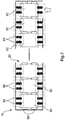
- FIG. 4 an automated cargo transportation arrangement 70 for moving a cargo unit (not shown) within an aircraft cargo compartment 22 is depicted.
- the transportation arrangement 70 comprises a first transport device 30, a second transport device 32, and a third transport device 34.
- the transport devices 30, 32, 34 are coupled to each other via couplings 52, which provide a mechanical, electrical, and/or pneumatic or hydraulic connection between the transport devices 30, 32, 34.
- the transport devices 30, 32, 34 are arranged in series, whereas a position of the transport devices 30, 32, 34 may be changed relative to each other by displacing the coupling 52 along the respective rounded edges 56.
- the arrows 72 indicate a displacement direction of two respective neighboring transport devices 30, 32, 34 as an example.
- a transport device 30, 32, 34 may have a length of about 50 cm and a breadth of about 50 cm, which corresponds to a total length of a three-part transportation arrangement 70 of about 150 cm.
- the transportation arrangement 70 may be provided in combination with a second transportation arrangement 70 which may be, in an example, locate parallel next to each other, while commonly carrying one cargo unit.
- a first transportation arrangement 70 may be positioned along a left longitudinal edge on the bottom plate of a cargo unit
- a second transportation arrangement 70 may be positioned at a right longitudinal edge of a cargo unit.
- the two transportation arrangements 70 may communicate directly with each other, for instance via a wireless data connection. This may allow a synchronization of the movement and any activities performed by the individual transportation arrangements 70 and respective transport devices 30, 32, 34.
- a communication between two commonly used transportation arrangements 70 may only be performed in a direct manner, without involving a centralized control unit or a loading system control unit.
- the transportation arrangement 70 may communicate via a data connection with a loading system control unit (not shown).
- a loading system control unit not shown.
- the synchronization of both transportation arrangements 70 relative to each other may be performed in a direct manner in order to avoid delays in the forwarding of data to avoid negative impacts on the vehicle synchronization.
- the communication between the transportation arrangements 70 and/or between transport devices 30, 32, 34 may be performed, for instance, via wireless means.
- the rounded edges and the couplings are formed such that a leading transport device 30, 32, 34 may change a moving direction while the following transport device 30, 32, 34 may continue a linear path.
- no curved area of the track is necessary and the track shape may have an exact orthogonal shape, which may simplify a structure of a cargo compartment floor 20 and thus lower cost.
- the shown example in Fig. 4 contains three transport devices 30, 32, 34, whereas the first transport device 30 and the third transport device 34 are identical, but rotated by 180 degrees.
- the middle or second transport device 32 comprises a different set of parts.
- the second transport device 32 comprises a power drive unit (PDU) 74.
- the power drive unit 74 is a cylindrical roll or wheel, which longitudinal rotational axis is arranged in a longitudinal direction of the transportation arrangement 70.
- the power drive unit 74 may, for instance, be raised lowered relative to the base body 36. In the raised position, the power drive unit 74 may pull a cargo unit in a direction transversely or orthogonally to a longitudinal direction of the transportation arrangement 70 above the transportation arrangement 70 such that it may be carried and transported by the transportation arrangement 70.
- the power drive unit 74 may start rotating, for instance, if a bottom plate of a cargo unit is detected at the power drive unit 74.
- a PDU 74 may be, for example, driven by an electromechanical motor.
- the second transport device 32 further comprises a control unit 76.
- the control unit 76 is adapted to control all transport devices 30, 32, 34 by using the electrical and data connections between the transport devices 30, 32, 34.
- the control unit 76 is configured to communicate with an aircraft loading system control unit (not shown) and/or to communicate with a second or any further transportation arrangement 70 for synchronization purposes.
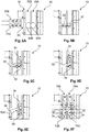
- a first transportation arrangement 70A and a second transportation arrangement 70B are provided at an entrance area outside the aircraft fuselage 10 in front of a cargo door 24. This may be done by, for instance, a cargo loader, which operates outside the aircraft.
- the transportation arrangements 70A, 70B are lifted on the cargo door level.
- the first transportation arrangement 70A is manually positioned in front of a gap in flex-downs. This may be performed by operating staff, which is located outside the cargo compartment 16.
- the cargo compartment comprises two floor channels 78A and 78B.
- the first transportation arrangement 70A moves in +y-direction (see Fig. 3 ) until a marking 80A is detected.
- the transportation arrangement 70A stops and a locking mechanism (see Fig. 3 ) between the first leading transport device 30 and a coupled second transport device 32 is opened.
- Fig. 5C the first transport device 30 starts moving in +x-direction, while the other two transport devices 32, 34 move further in +y-direction.
- the second transport device 32 once arrived at the marking 80A, starts moving in +y-direction, whereas the third transport device 34 continues moving in +x-direction. Once the third transport device 34 detects the first marking 80A, the third transport device starts moving in +y-direction.
- the locking mechanism 60 between the first transport device 30 and the second transport device 32 and the locking mechanism 60 between the second transport device 32 and the third transport device 34 is opened, and after concluding the direction change, is closed again.
- This may allow maintaining a stability of the entire transportation arrangement 70 after changing its direction.
- the shape of the transportation arrangement 70A, 70B changes from straight to an L-shaped design and then, after conclusion of the direction change, to a straight shape again.
- the first transportation arrangement 70A has, as shown in Fig. 5D , a straight shape in a direction longitudinal to the floor direction of the cargo compartment floor 20.
- the first, second, and third transport device 30, 32, 34 do not change their orientation, or in other words, do not rotate around an own axis.
- the direction change of the transportation arrangement 70A may, due to the rounded edges and the displaceable couplings, be performed without requiring additional curve space on the cargo compartment floor 20.
- the transportation arrangement 70A now moves in -x-direction until the second transport device 32 detects the first marking 80A.
- the middle or second transport device 32 is positioned such that it faces the cargo door and is positioned in front of the opening in the flex-downs.
- the second transportation arrangement 70B is shown in its final position. Analogous to the position of the first transportation arrangement 70A, with the difference, that the first transportation arrangement 70A is located in the first floor channel 78A, whereas the second transportation arrangement 70B is located and positioned in the second floor channel 78B. Both transportation arrangements may now move in +x- or -x-direction and are ready to receive cargo units for shifting the cargo units (not shown) within the cargo compartment 16.
- the method steps as shown in Fig. 5A to Fig. 5E are repeated in the same manner, with the only difference, that different markings are used as reference.
- the first marking 80A analogously the second marking 80B (see Fig. 5A ) are used.
- the markings may be detected via suitable sensors arranged at the transport devices 30, 32, 34.
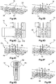
- Fig. 6A to Fig. 6H steps of a method for loading a cargo unit according to the invention are shown.
- the first and second transportation arrangement 70A, 70B are, analogously to Fig. 5F , positioned in the cargo compartment 16 on a cargo compartment floor 20.
- the second transportation arrangement 70B faces with its second transport device 32 a cargo door 24 area.
- the two transportation arrangements 70A, 70B are now able to move in +x- and -x-direction.
- Fig. 6B it is indicated, that the power drive units 74 of the second transport device 32 are lifted, once a cargo unit is moved over the power drive unit 74.
- the drives in the power drive unit 74 are triggered-started and the cargo unit (not shown) is conveyed in +y-direction until a latch (not shown) is reached.
- the latch serves as mechanical stop and detection for a maximum movement in +y-direction.
- Such latch may be a vertical clamp or similar, which allows a mechanical stop for the movement in y-direction.
- the transportation arrangements 70A, 70B haven been moved to a target position 84 in the cargo compartment 16.
- the location of the target position 84 may be detected by sensors using or detecting markings in the flex-downs.
- flex-downs contain a plurality of markings and read sensors count markings to identify and distinguish different positions within the cargo compartment floor 20.
- the transportation arrangements 70A, 70B begin to slow down or decrease their speed. For example, a latch may be raised in a previous step to provide a mechanical stop for the transportation arrangements 70A, 70B. After the target position 84 and/or mechanical stops are detected, the transportation arrangement stops, and the air cushions (see Fig.
- the method For unloading a cargo unit 82 from a cargo compartment 16 of an aircraft, the method is applied analogously in a reversed manner.
- a communication between a transportation arrangement, or a plurality of transportation arrangements 70A, 70B, or transport devices 30, 32, 34 with a loading system control unit may contain for example, the following steps.
- two transportation arrangements 70A, 70B may contain the following steps:
- the loading system control unit sends the message to the transportation arrangements 70A, 70B, that the cargo compartment 16 is ready for receiving the transportation arrangements 70A, 70B.
- the first transportation arrangement 70A and then following the next transportation arrangement 70B enter the cargo compartment 16.
- the first transportation arrangement 70A informs the loading system control unit that an end position is reached
- the second transportation arrangement 70B sends the message to the loading system control unit, that the end position is reached.
- both transportation arrangements 70A, 70B inform the loading system control unit that they are ready to receive a cargo unit.
- Steps for loading cargo units into a cargo compartment 16 of an aircraft fuselage 10 may comprise the following communication between different elements and components of the aircraft and the loading system control unit.
- the loading system control unit informs the transportation arrangements 70A, 70B that a cargo unit 82 enters the cargo compartment 16. Then the transportation arrangement 70A, 70B receives the cargo unit 82. Then the first transportation arrangement and then the second transportation arrangement 70A, 70B announce to the loading system control unit that the cargo unit 82 is received.
- the loading system control unit informs the transportation arrangement 70A, 70B to which target position the cargo unit 84 is supposed to be transported. The transportation arrangements 70A, 70B announce readiness to move in x-direction.
- the loading system control unit then sends a clearance to the transportation arrangement 70A, 70B to move.
- the transportation arrangements 70A, 70B start moving. During the movement, the first transportation arrangement 70A communicates with the second transportation arrangement 70B for synchronization purposes.
- the loading system control unit sends a message to the transportation arrangement 70A, 70B that the cargo unit 82 is lowered.
- the loading system control unit sends a command to the locking system for locking the cargo unit 84.
- the locking system sends a message to the loading system control unit, whether the locking procedure has been successful or not. If not, the locking procedure is repeated. Then the loading system control unit sends a command to the transportation arrangement 70A, 70B to return to the initial position.
- the transportation arrangements 70A, 70B announce this accordingly to the loading system control unit.
- the transportation arrangements 70A, 70B inform the loading system control unit that they are ready to receive a next cargo unit 82. For further cargo units 82, this process is repeated.
- the unloading of cargo units and the unloading of the transportation arrangements of the aircraft is done in a reversed manner analogously to the described method steps.
- a locking system for cargo units 82 on a cargo compartment floor 20 of a cargo compartment 16 is shown. Once the cargo units 82 are positioned at their respective target positions 84 (see Fig. 6G ), they need to be locked such that they cannot move during flight in order to avoid damages.
- the shown locking system relates to a locking of cargo units 82 at the cargo compartment floor 20 using fully automated cargo unit locking.
- the locking parts comprise x-latches 86 and yz-latches 88.
- X-latches provide a locking of a cargo unit 82 to prevent movement in x-direction
- yz-latches provide a locking and fixation of a cargo unit or several cargo units 82 in y- and/or z-direction.
- Latches may be electromechanically driven and may be raised up or lowered down via electromechanical motors or similar suitable means. An advantage may be that there is no human operator required within the cargo compartment 16.
- the x-latch 86 locks a cargo unit in x-direction.
- one latch may be driven by one electromechanical actuation unit (not shown).
- the lock and unlock position of each latch may be held securely by a pivotable magnetic spring (not shown).
- the yz-latches are adapted to lock the cargo units in z- and in y-direction. Two different types of xy-latches may be provided.
- a 2-spant latch is used, where the cargo unit 82 is located above two support frames of the cargo compartment floor 20.
- Each latch may include a guiding roller to support the cargo unit 82 in y-direction.
- one electromechanical actuation unit drives two latches 88,86.
- a 3-spant yz-latch is used, where the cargo unit 82 is located above three support frames of the cargo compartment floor 20.
- Each latch 88, 86 may include a guiding roller to support the cargo unit 82 in y-direction.
- the drive shaft may be centrally supported.
- one electromechanical actuation unit will drive two latches 88, 86.
- the yz-latch 88 may, in an example, have two independent sensor systems to detect a locking or an unloading position. Hall sensors may detect the position of the magnetic spring. In one example, two proximity sensors may be located at the struts of the latch to detect their position. Due to its more compact construction and the missing levers, the x-latch 86 may be only equipped with the hall sensors at the magnetic spring.
- the functional modules may be implemented as a programmed software module or procedures, respectively. However, one skilled in the art will understand that the functional modules may be implemented fully or partially in hardware. While the invention has been illustrated and described in detail in the drawings and foregoing description, such illustration and description are to be considered illustrative or exemplary and not restrictive. The invention is not limited to the disclosed embodiments. Other variations to the disclosed embodiments may be understood and effected by those skilled in the art and practicing the claimed invention, from a study of the drawings, the disclosure, and the appended claims.
Landscapes
- Engineering & Computer Science (AREA)
- Aviation & Aerospace Engineering (AREA)
- Mechanical Engineering (AREA)
- Loading Or Unloading Of Vehicles (AREA)
- Warehouses Or Storage Devices (AREA)
Claims (10)
- Automatisierte Frachttransportanordnung (70) zum Bewegen einer Frachteinheit innerhalb eines Luftfahrzeugfrachtraums, aufweisend eine erste und eine zweite Transporteinrichtung (30, 32), wobei jede Transporteinrichtung aufweist:- einen Grundkörper (36);- Verschiebemittel (38);wobei der Basiskörper angepasst ist, um die Frachteinheit zu tragen;
wobei das Verschiebemittel geeignet ist, den Basiskörper entlang eines Bodens (20) des Frachtraums senkrecht zur Längsachse des Luftfahrzeugs und danach entlang der Längsachse des Luftfahrzeugs ohne Drehung des Basiskörpers zu bewegen;
dadurch gekennzeichnet, dass
die erste und die zweite Transporteinrichtung durch eine verschiebbare Kupplung (52) bewegbar mit dem Grundkörper (36) jeder Transporteinrichtung (30, 32) verbunden sind;
die Position der Kupplung (52) ist derart verschiebbar, dass die Kupplungsrichtung zur zweiten Transporteinrichtung um mindestens 90 Grad veränderbar ist, während sich die Kupplung entlang von kreisförmigen Bahnen (54) abgerundeter Kanten (56) der ersten (30) und zweiten (32) Transporteinrichtung verschiebt, wobei die abgerundeten Kanten an Positionen zueinander quer über der Kupplung (52) vorgesehen sind, wenn beide Vorrichtungen (30, 32) auf der gleichen Längsachse positioniert sind; und
eine Position der ersten und zweiten Transporteinrichtung relativ zueinander durch Verschieben der Kopplung zwischen der ersten und zweiten Transporteinrichtung veränderbar ist. - Transportanordnung nach Anspruch 1, wobei die Kupplung zur Bereitstellung einer elektrischen und/oder mechanischen und/oder fluidischen Verbindung zu einer zweiten Transporteinrichtung (32) ausgebildet ist.
- Transportanordnung nach vorhergehendem Anspruch 1 oder 2, wobei die Transporteinrichtung ferner aufweisend:- eine Ladeeinheit-Aufnahmevorrichtung (46), die angepasst ist, um die Ladeeinheit über der Frachtraumbodenhöhe anzuheben und die Ladeeinheit so abzusenken, dass die Ladeeinheit auf der Zielposition ruht.
- Transportanordnung nach Anspruch 1, wobei die erste Transporteinrichtung (30, 32) über die Kupplung (52) mit der zweiten Transporteinrichtung (32, 34) elektrisch gekoppelt ist.
- Transportanordnung nach einem der Ansprüche 1 bis 4, wobei die abgerundeten Kanten derart ausgebildet sind, dass die Kupplung gleichzeitig entlang der abgerundeten Kanten der ersten und zweiten Transporteinrichtung verschiebbar ist, so dass eine horizontale Winkelausrichtung der ersten und der zweiten Transporteinrichtung relativ zu einer länglichen Ladebodenrichtung (20) beibehalten wird.
- Transportanordnung nach einem der Ansprüche 1 bis 5, wobei die Transportanordnung ferner eine dritte Transporteinrichtung (34) aufweist;
wobei die Transporteinrichtungen der Transportanordnung in Reihe zueinander angeordnet sind. - Verfahren zum Bereitstellen einer Transportanordnung (70) an einer Startposition auf einem Boden (20) eines Frachtraums (16) und zum Beladen einer Frachteinheit (82) in den Frachtraum eines Flugzeugs, wobei das Verfahren aufweist:- Bereitstellen der Transportanordnung nach den Ansprüchen 1 bis 6 in einem Eingangsbereich des Frachtraumbodens;
wobei die Transporteinrichtungen in einer Richtung quer zu einer Längsrichtung des Flugzeugbodens in Reihe angeordnet sind;- Bewegen der Transportanordnung quer zur Längsrichtung des Bodens;- Verschieben einer Transporteinrichtung (30, 32) relativ zu einer nachfolgenden gekoppelten Transporteinrichtung (32, 34) derart, dass sich die Transporteinrichtung in Längsrichtung bewegt;- Positionieren der Transportanordnung an einer Startposition (80A, 80B), sodass die Transportanordnung eine Frachteinheit (82) aufnehmen kann und so angeordnet ist, dass sie sich in der Längsrichtung bewegt. - Verfahren nach Anspruch 7, dadurch gekennzeichnet, dass in dem Schritt des Verschiebens der ersten Transporteinrichtung eine horizontale Winkelausrichtung der ersten und zweiten Transporteinrichtung relativ zur Bodenlängsrichtung beibehalten wird.
- Verfahren nach Anspruch 7 oder 8, wobei der Schritt des Verschiebens der ersten Transporteinrichtung ein Öffnen und/oder Schließen eines Verriegelungssystems (60) zwischen der ersten und der zweiten Transporteinrichtung aufweist.
- Verfahren nach den Ansprüchen 7 oder 8 oder 9, weiterhin aufweisend die Schritte:- Empfangen der Frachteinheit durch die Transportanordnung;- Bewegen der Transportanordnung mit der Frachteinheit zu einer Zielposition (84);- Ablegen der Frachteinheit durch die Transportanordnung derart, dass die Frachteinheit auf der Zielposition ruht.
Priority Applications (2)
| Application Number | Priority Date | Filing Date | Title |
|---|---|---|---|
| EP13189917.1A EP2865596B1 (de) | 2013-10-23 | 2013-10-23 | Automatische Transportvorrichtung für Frachtladesystem |
| US14/516,788 US9340286B2 (en) | 2013-10-23 | 2014-10-17 | Automatic transport device for cargo loading system |
Applications Claiming Priority (1)
| Application Number | Priority Date | Filing Date | Title |
|---|---|---|---|
| EP13189917.1A EP2865596B1 (de) | 2013-10-23 | 2013-10-23 | Automatische Transportvorrichtung für Frachtladesystem |
Publications (2)
| Publication Number | Publication Date |
|---|---|
| EP2865596A1 EP2865596A1 (de) | 2015-04-29 |
| EP2865596B1 true EP2865596B1 (de) | 2018-03-28 |
Family
ID=49484159
Family Applications (1)
| Application Number | Title | Priority Date | Filing Date |
|---|---|---|---|
| EP13189917.1A Not-in-force EP2865596B1 (de) | 2013-10-23 | 2013-10-23 | Automatische Transportvorrichtung für Frachtladesystem |
Country Status (2)
| Country | Link |
|---|---|
| US (1) | US9340286B2 (de) |
| EP (1) | EP2865596B1 (de) |
Families Citing this family (15)
| Publication number | Priority date | Publication date | Assignee | Title |
|---|---|---|---|---|
| EP2899124B1 (de) * | 2014-01-27 | 2018-07-25 | Airbus Operations GmbH | Fahrzeugladeraum, System, und Fahrzeug |
| EP3106390B1 (de) * | 2015-06-17 | 2018-08-08 | Airbus Operations GmbH | Vorrichtung und verfahren zum bewegen von fracht in einem flugzeug |
| US10005564B1 (en) | 2017-05-05 | 2018-06-26 | Goodrich Corporation | Autonomous cargo handling system and method |
| DE102017128238B3 (de) * | 2017-11-29 | 2018-11-29 | Airbus Operations Gmbh | System zum Bewegen von Lasten in einem Flugzeug |
| JP2019152616A (ja) * | 2018-03-06 | 2019-09-12 | オムロン株式会社 | 光測距センサ |
| US10800527B2 (en) * | 2018-08-17 | 2020-10-13 | Goodrich Corporation | Omni directional turntable assembly |
| US11203431B2 (en) * | 2018-10-22 | 2021-12-21 | Goodrich Corporation | Self-calibrating multi-sensor cargo handling system and method |
| US11459104B2 (en) | 2018-11-06 | 2022-10-04 | Goodrich Corporation | Method for verifying latch engagement for cargo handling systems |
| WO2021046555A1 (en) * | 2019-09-05 | 2021-03-11 | Zsm Holdings Llc | Systems, methods, and vehicles for transporting large cargo onto and off a transport vehicle |
| CA3153554A1 (en) | 2019-09-05 | 2021-03-11 | Zsm Holdings Llc | Systems and methods for loading and unloading a cargo aircraft |
| US11434007B2 (en) | 2019-09-20 | 2022-09-06 | Goodrich Corporation | Powered rail mounted cargo tug and cargo platform |
| US11618640B2 (en) * | 2020-04-20 | 2023-04-04 | The Boeing Company | Methods and apparatus to position a cargo unit in a cargo compartment of an aircraft |
| KR102410385B1 (ko) * | 2020-07-30 | 2022-06-16 | 김재모 | 운송 드론 연결형 팔레트 |
| FR3115768B1 (fr) * | 2020-10-29 | 2025-03-14 | Daher Aerospace | Dispositif et procédé d’utilisation de la cabine passagers d’un aéronef pour le transport de marchandises |
| KR20230107983A (ko) * | 2022-01-10 | 2023-07-18 | 현대자동차주식회사 | 화물 로딩 및 언로딩 장치 |
Family Cites Families (20)
| Publication number | Priority date | Publication date | Assignee | Title |
|---|---|---|---|---|
| GB1326304A (en) * | 1970-09-08 | 1973-08-08 | Air Preheater | Material handling apparatus |
| US3709450A (en) * | 1970-12-11 | 1973-01-09 | Boeing Co | Cargo loading system for aircraft |
| US3899092A (en) * | 1973-07-03 | 1975-08-12 | Arnold B Nordstrom | Cargo-carrying structural modules |
| US4544319A (en) * | 1983-09-22 | 1985-10-01 | The Boeing Company | Cargo transfer system |
| US4541768A (en) * | 1983-10-13 | 1985-09-17 | Fmc Corporation | Container trailer |
| US4860973A (en) * | 1988-04-27 | 1989-08-29 | The Boeing Company | Cargo conveying system |
| IT1221804B (it) * | 1988-05-13 | 1990-07-12 | Sefind Srl | Dispositivo agevolatore di carico per stive di aeromobili |
| US4929133A (en) | 1989-04-14 | 1990-05-29 | Airborne Express, Inc. | Loading pallet for aircraft cargo containers |
| FR2682930A1 (fr) * | 1991-10-28 | 1993-04-30 | Heli Rhone Alpes | Installation sanitaire pour helicoptere notamment. |
| DE19634791C1 (de) | 1996-08-29 | 1997-12-04 | Daimler Benz Aerospace Airbus | X-Riegelelement für ein System zum Verriegeln von Luftfrachtladeeinheiten in einem Frachtladeraum eines Flugzeuges |
| FR2798915B1 (fr) * | 1999-09-27 | 2001-12-21 | Savoye Automated Storage | Magasin de stockage compact automatise |
| US6517028B2 (en) * | 2000-08-11 | 2003-02-11 | Telair International Gmbh | Freight loading system |
| DE10238153A1 (de) | 2002-08-15 | 2004-03-25 | Wittenstein Ag | Verriegelungseinrichtung für Fahrzeuge, insbesondere für Flugzeuge |
| US7785056B2 (en) * | 2006-08-22 | 2010-08-31 | The Boeing Company | Cargo transport system and method |
| CH702765A2 (de) * | 2010-02-26 | 2011-08-31 | Stoecklin Logistik Ag | Regalbedienvorrichtung. |
| DE102010035099A1 (de) | 2010-08-23 | 2012-02-23 | Airbus Operations Gmbh | Vollautomatisches Frachtladesystem |
| EP2665646B1 (de) | 2011-01-19 | 2018-08-08 | Telair International GmbH | Ladesystem für ein flugzeug und verfahren zur förderung eines frachtstücks auf einem frachtdeck |
| IL222208A (en) * | 2012-09-27 | 2017-02-28 | Israel Aerospace Ind Ltd | Loading system, method and facility |
| EP2815969B1 (de) * | 2013-06-17 | 2018-08-08 | Airbus Operations GmbH | Frachtbefestigungssystem |
| EP2815970B1 (de) * | 2013-06-21 | 2018-04-04 | Airbus Operations GmbH | System und Verfahren zum Be- und Entladen eines Laderaums |
-
2013
- 2013-10-23 EP EP13189917.1A patent/EP2865596B1/de not_active Not-in-force
-
2014
- 2014-10-17 US US14/516,788 patent/US9340286B2/en not_active Expired - Fee Related
Non-Patent Citations (1)
| Title |
|---|
| None * |
Also Published As
| Publication number | Publication date |
|---|---|
| US20150108276A1 (en) | 2015-04-23 |
| EP2865596A1 (de) | 2015-04-29 |
| US9340286B2 (en) | 2016-05-17 |
Similar Documents
| Publication | Publication Date | Title |
|---|---|---|
| US9340286B2 (en) | Automatic transport device for cargo loading system | |
| JP7774601B2 (ja) | 保管システムのためのサービス車両 | |
| EP3345833B1 (de) | Frachthandhabungssysteme und -verfahren | |
| EP3713855B1 (de) | Automatisiertes lager- und entnahmesystem | |
| EP3774535B1 (de) | Autonomes paketregalbedienungssystem mit einer drohne | |
| US9452901B2 (en) | System and method for loading and unloading a cargo compartment | |
| CN101181957B (zh) | 物品输送设备 | |
| CN101261950B (zh) | 物品处理设备及其控制方法 | |
| CN112262085B (zh) | 具有带锁定装置以锁定远程操作车辆的容器存取站的储存网格 | |
| WO2009139859A9 (en) | High density storage facility | |
| CN109969377B (zh) | 飞行器内移动货物的系统、运输车、锁定装置和运行方法 | |
| WO2014058614A1 (en) | Aircraft cargo compartment container crane system | |
| CN115477013B (zh) | 一种无人机空运空投系统 | |
| US20200095075A1 (en) | System for Loading and Unloading Moving Vehicles | |
| EP3156329B1 (de) | System zum bewegen von lasten und halten von fracht | |
| CN110949671A (zh) | 无人机货舱、无人机和装卸货物的方法 | |
| CN112109597A (zh) | 将部件装载到车辆中的方法 | |
| CN116118905B (zh) | 智能配送站、无人车、配送agv和无人配送系统 | |
| EP3562763B1 (de) | System zur automatisierten speicherung und zum automatisierten abruf | |
| WO2023205436A2 (en) | Automating delivery vehicle loading and unloading | |
| EP3390252B1 (de) | Anlage und verfahren zum automatischen beladen eines behälters | |
| EP3789281B1 (de) | Automatisch funktionierendes fahrzeugkarosserieentladesystem | |
| CN121219211A (zh) | 用于递送储存容器的系统 | |
| CN117957178A (zh) | 容器缓冲组件、包括该容器缓冲组件的储存系统及相关方法 | |
| HK40083952A (en) | Service vehicle for a storage system |
Legal Events
| Date | Code | Title | Description |
|---|---|---|---|
| PUAI | Public reference made under article 153(3) epc to a published international application that has entered the european phase |
Free format text: ORIGINAL CODE: 0009012 |
|
| 17P | Request for examination filed |
Effective date: 20131023 |
|
| AK | Designated contracting states |
Kind code of ref document: A1 Designated state(s): AL AT BE BG CH CY CZ DE DK EE ES FI FR GB GR HR HU IE IS IT LI LT LU LV MC MK MT NL NO PL PT RO RS SE SI SK SM TR |
|
| AX | Request for extension of the european patent |
Extension state: BA ME |
|
| R17P | Request for examination filed (corrected) |
Effective date: 20150611 |
|
| RBV | Designated contracting states (corrected) |
Designated state(s): AL AT BE BG CH CY CZ DE DK EE ES FI FR GB GR HR HU IE IS IT LI LT LU LV MC MK MT NL NO PL PT RO RS SE SI SK SM TR |
|
| REG | Reference to a national code |
Ref country code: DE Ref legal event code: R079 Ref document number: 602013034999 Country of ref document: DE Free format text: PREVIOUS MAIN CLASS: B64D0009000000 Ipc: B64C0001200000 |
|
| RIC1 | Information provided on ipc code assigned before grant |
Ipc: B64D 9/00 20060101ALI20170328BHEP Ipc: B64C 1/20 20060101AFI20170328BHEP |
|
| GRAP | Despatch of communication of intention to grant a patent |
Free format text: ORIGINAL CODE: EPIDOSNIGR1 |
|
| STAA | Information on the status of an ep patent application or granted ep patent |
Free format text: STATUS: GRANT OF PATENT IS INTENDED |
|
| INTG | Intention to grant announced |
Effective date: 20170518 |
|
| GRAJ | Information related to disapproval of communication of intention to grant by the applicant or resumption of examination proceedings by the epo deleted |
Free format text: ORIGINAL CODE: EPIDOSDIGR1 |
|
| STAA | Information on the status of an ep patent application or granted ep patent |
Free format text: STATUS: REQUEST FOR EXAMINATION WAS MADE |
|
| GRAP | Despatch of communication of intention to grant a patent |
Free format text: ORIGINAL CODE: EPIDOSNIGR1 |
|
| STAA | Information on the status of an ep patent application or granted ep patent |
Free format text: STATUS: GRANT OF PATENT IS INTENDED |
|
| INTC | Intention to grant announced (deleted) | ||
| INTG | Intention to grant announced |
Effective date: 20171025 |
|
| GRAS | Grant fee paid |
Free format text: ORIGINAL CODE: EPIDOSNIGR3 |
|
| GRAA | (expected) grant |
Free format text: ORIGINAL CODE: 0009210 |
|
| STAA | Information on the status of an ep patent application or granted ep patent |
Free format text: STATUS: THE PATENT HAS BEEN GRANTED |
|
| AK | Designated contracting states |
Kind code of ref document: B1 Designated state(s): AL AT BE BG CH CY CZ DE DK EE ES FI FR GB GR HR HU IE IS IT LI LT LU LV MC MK MT NL NO PL PT RO RS SE SI SK SM TR |
|
| REG | Reference to a national code |
Ref country code: GB Ref legal event code: FG4D |
|
| REG | Reference to a national code |
Ref country code: CH Ref legal event code: EP |
|
| REG | Reference to a national code |
Ref country code: AT Ref legal event code: REF Ref document number: 983164 Country of ref document: AT Kind code of ref document: T Effective date: 20180415 |
|
| REG | Reference to a national code |
Ref country code: IE Ref legal event code: FG4D |
|
| REG | Reference to a national code |
Ref country code: DE Ref legal event code: R096 Ref document number: 602013034999 Country of ref document: DE |
|
| PG25 | Lapsed in a contracting state [announced via postgrant information from national office to epo] |
Ref country code: HR Free format text: LAPSE BECAUSE OF FAILURE TO SUBMIT A TRANSLATION OF THE DESCRIPTION OR TO PAY THE FEE WITHIN THE PRESCRIBED TIME-LIMIT Effective date: 20180328 Ref country code: NO Free format text: LAPSE BECAUSE OF FAILURE TO SUBMIT A TRANSLATION OF THE DESCRIPTION OR TO PAY THE FEE WITHIN THE PRESCRIBED TIME-LIMIT Effective date: 20180628 Ref country code: FI Free format text: LAPSE BECAUSE OF FAILURE TO SUBMIT A TRANSLATION OF THE DESCRIPTION OR TO PAY THE FEE WITHIN THE PRESCRIBED TIME-LIMIT Effective date: 20180328 Ref country code: LT Free format text: LAPSE BECAUSE OF FAILURE TO SUBMIT A TRANSLATION OF THE DESCRIPTION OR TO PAY THE FEE WITHIN THE PRESCRIBED TIME-LIMIT Effective date: 20180328 |
|
| REG | Reference to a national code |
Ref country code: NL Ref legal event code: MP Effective date: 20180328 |
|
| REG | Reference to a national code |
Ref country code: LT Ref legal event code: MG4D |
|
| PG25 | Lapsed in a contracting state [announced via postgrant information from national office to epo] |
Ref country code: LV Free format text: LAPSE BECAUSE OF FAILURE TO SUBMIT A TRANSLATION OF THE DESCRIPTION OR TO PAY THE FEE WITHIN THE PRESCRIBED TIME-LIMIT Effective date: 20180328 Ref country code: SE Free format text: LAPSE BECAUSE OF FAILURE TO SUBMIT A TRANSLATION OF THE DESCRIPTION OR TO PAY THE FEE WITHIN THE PRESCRIBED TIME-LIMIT Effective date: 20180328 Ref country code: GR Free format text: LAPSE BECAUSE OF FAILURE TO SUBMIT A TRANSLATION OF THE DESCRIPTION OR TO PAY THE FEE WITHIN THE PRESCRIBED TIME-LIMIT Effective date: 20180629 Ref country code: RS Free format text: LAPSE BECAUSE OF FAILURE TO SUBMIT A TRANSLATION OF THE DESCRIPTION OR TO PAY THE FEE WITHIN THE PRESCRIBED TIME-LIMIT Effective date: 20180328 Ref country code: BG Free format text: LAPSE BECAUSE OF FAILURE TO SUBMIT A TRANSLATION OF THE DESCRIPTION OR TO PAY THE FEE WITHIN THE PRESCRIBED TIME-LIMIT Effective date: 20180628 |
|
| REG | Reference to a national code |
Ref country code: FR Ref legal event code: PLFP Year of fee payment: 6 |
|
| PG25 | Lapsed in a contracting state [announced via postgrant information from national office to epo] |
Ref country code: RO Free format text: LAPSE BECAUSE OF FAILURE TO SUBMIT A TRANSLATION OF THE DESCRIPTION OR TO PAY THE FEE WITHIN THE PRESCRIBED TIME-LIMIT Effective date: 20180328 Ref country code: IT Free format text: LAPSE BECAUSE OF FAILURE TO SUBMIT A TRANSLATION OF THE DESCRIPTION OR TO PAY THE FEE WITHIN THE PRESCRIBED TIME-LIMIT Effective date: 20180328 Ref country code: EE Free format text: LAPSE BECAUSE OF FAILURE TO SUBMIT A TRANSLATION OF THE DESCRIPTION OR TO PAY THE FEE WITHIN THE PRESCRIBED TIME-LIMIT Effective date: 20180328 Ref country code: AL Free format text: LAPSE BECAUSE OF FAILURE TO SUBMIT A TRANSLATION OF THE DESCRIPTION OR TO PAY THE FEE WITHIN THE PRESCRIBED TIME-LIMIT Effective date: 20180328 Ref country code: PL Free format text: LAPSE BECAUSE OF FAILURE TO SUBMIT A TRANSLATION OF THE DESCRIPTION OR TO PAY THE FEE WITHIN THE PRESCRIBED TIME-LIMIT Effective date: 20180328 Ref country code: NL Free format text: LAPSE BECAUSE OF FAILURE TO SUBMIT A TRANSLATION OF THE DESCRIPTION OR TO PAY THE FEE WITHIN THE PRESCRIBED TIME-LIMIT Effective date: 20180328 Ref country code: ES Free format text: LAPSE BECAUSE OF FAILURE TO SUBMIT A TRANSLATION OF THE DESCRIPTION OR TO PAY THE FEE WITHIN THE PRESCRIBED TIME-LIMIT Effective date: 20180328 |
|
| PG25 | Lapsed in a contracting state [announced via postgrant information from national office to epo] |
Ref country code: CZ Free format text: LAPSE BECAUSE OF FAILURE TO SUBMIT A TRANSLATION OF THE DESCRIPTION OR TO PAY THE FEE WITHIN THE PRESCRIBED TIME-LIMIT Effective date: 20180328 Ref country code: SK Free format text: LAPSE BECAUSE OF FAILURE TO SUBMIT A TRANSLATION OF THE DESCRIPTION OR TO PAY THE FEE WITHIN THE PRESCRIBED TIME-LIMIT Effective date: 20180328 Ref country code: SM Free format text: LAPSE BECAUSE OF FAILURE TO SUBMIT A TRANSLATION OF THE DESCRIPTION OR TO PAY THE FEE WITHIN THE PRESCRIBED TIME-LIMIT Effective date: 20180328 |
|
| REG | Reference to a national code |
Ref country code: AT Ref legal event code: MK05 Ref document number: 983164 Country of ref document: AT Kind code of ref document: T Effective date: 20180328 |
|
| PG25 | Lapsed in a contracting state [announced via postgrant information from national office to epo] |
Ref country code: PT Free format text: LAPSE BECAUSE OF FAILURE TO SUBMIT A TRANSLATION OF THE DESCRIPTION OR TO PAY THE FEE WITHIN THE PRESCRIBED TIME-LIMIT Effective date: 20180730 |
|
| REG | Reference to a national code |
Ref country code: DE Ref legal event code: R097 Ref document number: 602013034999 Country of ref document: DE |
|
| PG25 | Lapsed in a contracting state [announced via postgrant information from national office to epo] |
Ref country code: DK Free format text: LAPSE BECAUSE OF FAILURE TO SUBMIT A TRANSLATION OF THE DESCRIPTION OR TO PAY THE FEE WITHIN THE PRESCRIBED TIME-LIMIT Effective date: 20180328 Ref country code: AT Free format text: LAPSE BECAUSE OF FAILURE TO SUBMIT A TRANSLATION OF THE DESCRIPTION OR TO PAY THE FEE WITHIN THE PRESCRIBED TIME-LIMIT Effective date: 20180328 |
|
| PLBE | No opposition filed within time limit |
Free format text: ORIGINAL CODE: 0009261 |
|
| STAA | Information on the status of an ep patent application or granted ep patent |
Free format text: STATUS: NO OPPOSITION FILED WITHIN TIME LIMIT |
|
| 26N | No opposition filed |
Effective date: 20190103 |
|
| PG25 | Lapsed in a contracting state [announced via postgrant information from national office to epo] |
Ref country code: SI Free format text: LAPSE BECAUSE OF FAILURE TO SUBMIT A TRANSLATION OF THE DESCRIPTION OR TO PAY THE FEE WITHIN THE PRESCRIBED TIME-LIMIT Effective date: 20180328 |
|
| REG | Reference to a national code |
Ref country code: CH Ref legal event code: PL |
|
| REG | Reference to a national code |
Ref country code: BE Ref legal event code: MM Effective date: 20181031 |
|
| PG25 | Lapsed in a contracting state [announced via postgrant information from national office to epo] |
Ref country code: LU Free format text: LAPSE BECAUSE OF NON-PAYMENT OF DUE FEES Effective date: 20181023 Ref country code: MC Free format text: LAPSE BECAUSE OF FAILURE TO SUBMIT A TRANSLATION OF THE DESCRIPTION OR TO PAY THE FEE WITHIN THE PRESCRIBED TIME-LIMIT Effective date: 20180328 |
|
| REG | Reference to a national code |
Ref country code: IE Ref legal event code: MM4A |
|
| PG25 | Lapsed in a contracting state [announced via postgrant information from national office to epo] |
Ref country code: CH Free format text: LAPSE BECAUSE OF NON-PAYMENT OF DUE FEES Effective date: 20181031 Ref country code: LI Free format text: LAPSE BECAUSE OF NON-PAYMENT OF DUE FEES Effective date: 20181031 Ref country code: BE Free format text: LAPSE BECAUSE OF NON-PAYMENT OF DUE FEES Effective date: 20181031 |
|
| PG25 | Lapsed in a contracting state [announced via postgrant information from national office to epo] |
Ref country code: IE Free format text: LAPSE BECAUSE OF NON-PAYMENT OF DUE FEES Effective date: 20181023 |
|
| PG25 | Lapsed in a contracting state [announced via postgrant information from national office to epo] |
Ref country code: MT Free format text: LAPSE BECAUSE OF NON-PAYMENT OF DUE FEES Effective date: 20181023 |
|
| PGFP | Annual fee paid to national office [announced via postgrant information from national office to epo] |
Ref country code: DE Payment date: 20191021 Year of fee payment: 7 |
|
| PGFP | Annual fee paid to national office [announced via postgrant information from national office to epo] |
Ref country code: FR Payment date: 20191028 Year of fee payment: 7 |
|
| PG25 | Lapsed in a contracting state [announced via postgrant information from national office to epo] |
Ref country code: TR Free format text: LAPSE BECAUSE OF FAILURE TO SUBMIT A TRANSLATION OF THE DESCRIPTION OR TO PAY THE FEE WITHIN THE PRESCRIBED TIME-LIMIT Effective date: 20180328 |
|
| PGFP | Annual fee paid to national office [announced via postgrant information from national office to epo] |
Ref country code: GB Payment date: 20191021 Year of fee payment: 7 |
|
| PG25 | Lapsed in a contracting state [announced via postgrant information from national office to epo] |
Ref country code: HU Free format text: LAPSE BECAUSE OF FAILURE TO SUBMIT A TRANSLATION OF THE DESCRIPTION OR TO PAY THE FEE WITHIN THE PRESCRIBED TIME-LIMIT; INVALID AB INITIO Effective date: 20131023 Ref country code: CY Free format text: LAPSE BECAUSE OF FAILURE TO SUBMIT A TRANSLATION OF THE DESCRIPTION OR TO PAY THE FEE WITHIN THE PRESCRIBED TIME-LIMIT Effective date: 20180328 Ref country code: MK Free format text: LAPSE BECAUSE OF NON-PAYMENT OF DUE FEES Effective date: 20180328 |
|
| PG25 | Lapsed in a contracting state [announced via postgrant information from national office to epo] |
Ref country code: IS Free format text: LAPSE BECAUSE OF FAILURE TO SUBMIT A TRANSLATION OF THE DESCRIPTION OR TO PAY THE FEE WITHIN THE PRESCRIBED TIME-LIMIT Effective date: 20180728 |
|
| REG | Reference to a national code |
Ref country code: DE Ref legal event code: R119 Ref document number: 602013034999 Country of ref document: DE |
|
| GBPC | Gb: european patent ceased through non-payment of renewal fee |
Effective date: 20201023 |
|
| PG25 | Lapsed in a contracting state [announced via postgrant information from national office to epo] |
Ref country code: FR Free format text: LAPSE BECAUSE OF NON-PAYMENT OF DUE FEES Effective date: 20201031 Ref country code: DE Free format text: LAPSE BECAUSE OF NON-PAYMENT OF DUE FEES Effective date: 20210501 |
|
| PG25 | Lapsed in a contracting state [announced via postgrant information from national office to epo] |
Ref country code: GB Free format text: LAPSE BECAUSE OF NON-PAYMENT OF DUE FEES Effective date: 20201023 |