EP2865610B1 - Doppelaerosolvorrichtung - Google Patents
Doppelaerosolvorrichtung Download PDFInfo
- Publication number
- EP2865610B1 EP2865610B1 EP13807225.1A EP13807225A EP2865610B1 EP 2865610 B1 EP2865610 B1 EP 2865610B1 EP 13807225 A EP13807225 A EP 13807225A EP 2865610 B1 EP2865610 B1 EP 2865610B1
- Authority
- EP
- European Patent Office
- Prior art keywords
- pouch
- container
- content
- inner container
- double
- Prior art date
- Legal status (The legal status is an assumption and is not a legal conclusion. Google has not performed a legal analysis and makes no representation as to the accuracy of the status listed.)
- Not-in-force
Links
Images










Classifications
-
- A—HUMAN NECESSITIES
- A45—HAND OR TRAVELLING ARTICLES
- A45D—HAIRDRESSING OR SHAVING EQUIPMENT; EQUIPMENT FOR COSMETICS OR COSMETIC TREATMENTS, e.g. FOR MANICURING OR PEDICURING
- A45D19/00—Devices for washing the hair or the scalp; Similar devices for colouring the hair
- A45D19/02—Hand-actuated implements, e.g. hand-actuated spray heads
-
- B—PERFORMING OPERATIONS; TRANSPORTING
- B65—CONVEYING; PACKING; STORING; HANDLING THIN OR FILAMENTARY MATERIAL
- B65D—CONTAINERS FOR STORAGE OR TRANSPORT OF ARTICLES OR MATERIALS, e.g. BAGS, BARRELS, BOTTLES, BOXES, CANS, CARTONS, CRATES, DRUMS, JARS, TANKS, HOPPERS, FORWARDING CONTAINERS; ACCESSORIES, CLOSURES, OR FITTINGS THEREFOR; PACKAGING ELEMENTS; PACKAGES
- B65D81/00—Containers, packaging elements, or packages, for contents presenting particular transport or storage problems, or adapted to be used for non-packaging purposes after removal of contents
- B65D81/32—Containers, packaging elements, or packages, for contents presenting particular transport or storage problems, or adapted to be used for non-packaging purposes after removal of contents for packaging two or more different materials which must be maintained separate prior to use in admixture
-
- B—PERFORMING OPERATIONS; TRANSPORTING
- B65—CONVEYING; PACKING; STORING; HANDLING THIN OR FILAMENTARY MATERIAL
- B65D—CONTAINERS FOR STORAGE OR TRANSPORT OF ARTICLES OR MATERIALS, e.g. BAGS, BARRELS, BOTTLES, BOXES, CANS, CARTONS, CRATES, DRUMS, JARS, TANKS, HOPPERS, FORWARDING CONTAINERS; ACCESSORIES, CLOSURES, OR FITTINGS THEREFOR; PACKAGING ELEMENTS; PACKAGES
- B65D83/00—Containers or packages with special means for dispensing contents
- B65D83/14—Containers for dispensing liquid or semi-liquid contents by internal gaseous pressure, i.e. aerosol containers comprising propellant
- B65D83/32—Dip-tubes
-
- B—PERFORMING OPERATIONS; TRANSPORTING
- B65—CONVEYING; PACKING; STORING; HANDLING THIN OR FILAMENTARY MATERIAL
- B65D—CONTAINERS FOR STORAGE OR TRANSPORT OF ARTICLES OR MATERIALS, e.g. BAGS, BARRELS, BOTTLES, BOXES, CANS, CARTONS, CRATES, DRUMS, JARS, TANKS, HOPPERS, FORWARDING CONTAINERS; ACCESSORIES, CLOSURES, OR FITTINGS THEREFOR; PACKAGING ELEMENTS; PACKAGES
- B65D83/00—Containers or packages with special means for dispensing contents
- B65D83/14—Containers for dispensing liquid or semi-liquid contents by internal gaseous pressure, i.e. aerosol containers comprising propellant
- B65D83/38—Details of the container body
- B65D83/382—Details of the container body the container body or a closure attached to the container body must be punctured before first use
-
- B—PERFORMING OPERATIONS; TRANSPORTING
- B65—CONVEYING; PACKING; STORING; HANDLING THIN OR FILAMENTARY MATERIAL
- B65D—CONTAINERS FOR STORAGE OR TRANSPORT OF ARTICLES OR MATERIALS, e.g. BAGS, BARRELS, BOTTLES, BOXES, CANS, CARTONS, CRATES, DRUMS, JARS, TANKS, HOPPERS, FORWARDING CONTAINERS; ACCESSORIES, CLOSURES, OR FITTINGS THEREFOR; PACKAGING ELEMENTS; PACKAGES
- B65D83/00—Containers or packages with special means for dispensing contents
- B65D83/14—Containers for dispensing liquid or semi-liquid contents by internal gaseous pressure, i.e. aerosol containers comprising propellant
- B65D83/60—Containers for dispensing liquid or semi-liquid contents by internal gaseous pressure, i.e. aerosol containers comprising propellant with contents and propellant separated
- B65D83/62—Containers for dispensing liquid or semi-liquid contents by internal gaseous pressure, i.e. aerosol containers comprising propellant with contents and propellant separated by membranes, bags or the like
-
- B—PERFORMING OPERATIONS; TRANSPORTING
- B65—CONVEYING; PACKING; STORING; HANDLING THIN OR FILAMENTARY MATERIAL
- B65D—CONTAINERS FOR STORAGE OR TRANSPORT OF ARTICLES OR MATERIALS, e.g. BAGS, BARRELS, BOTTLES, BOXES, CANS, CARTONS, CRATES, DRUMS, JARS, TANKS, HOPPERS, FORWARDING CONTAINERS; ACCESSORIES, CLOSURES, OR FITTINGS THEREFOR; PACKAGING ELEMENTS; PACKAGES
- B65D83/00—Containers or packages with special means for dispensing contents
- B65D83/14—Containers for dispensing liquid or semi-liquid contents by internal gaseous pressure, i.e. aerosol containers comprising propellant
- B65D83/68—Dispensing two or more contents
-
- B—PERFORMING OPERATIONS; TRANSPORTING
- B65—CONVEYING; PACKING; STORING; HANDLING THIN OR FILAMENTARY MATERIAL
- B65D—CONTAINERS FOR STORAGE OR TRANSPORT OF ARTICLES OR MATERIALS, e.g. BAGS, BARRELS, BOTTLES, BOXES, CANS, CARTONS, CRATES, DRUMS, JARS, TANKS, HOPPERS, FORWARDING CONTAINERS; ACCESSORIES, CLOSURES, OR FITTINGS THEREFOR; PACKAGING ELEMENTS; PACKAGES
- B65D83/00—Containers or packages with special means for dispensing contents
- B65D83/14—Containers for dispensing liquid or semi-liquid contents by internal gaseous pressure, i.e. aerosol containers comprising propellant
- B65D83/68—Dispensing two or more contents
- B65D83/682—Dispensing two or more contents initially separated and subsequently mixed
-
- A—HUMAN NECESSITIES
- A45—HAND OR TRAVELLING ARTICLES
- A45D—HAIRDRESSING OR SHAVING EQUIPMENT; EQUIPMENT FOR COSMETICS OR COSMETIC TREATMENTS, e.g. FOR MANICURING OR PEDICURING
- A45D2200/00—Details not otherwise provided for in A45D
- A45D2200/05—Details of containers
- A45D2200/053—Transparent containers
-
- A—HUMAN NECESSITIES
- A45—HAND OR TRAVELLING ARTICLES
- A45D—HAIRDRESSING OR SHAVING EQUIPMENT; EQUIPMENT FOR COSMETICS OR COSMETIC TREATMENTS, e.g. FOR MANICURING OR PEDICURING
- A45D2200/00—Details not otherwise provided for in A45D
- A45D2200/05—Details of containers
- A45D2200/054—Means for supplying liquid to the outlet of the container
- A45D2200/057—Spray nozzles; Generating atomised liquid
-
- A—HUMAN NECESSITIES
- A45—HAND OR TRAVELLING ARTICLES
- A45D—HAIRDRESSING OR SHAVING EQUIPMENT; EQUIPMENT FOR COSMETICS OR COSMETIC TREATMENTS, e.g. FOR MANICURING OR PEDICURING
- A45D2200/00—Details not otherwise provided for in A45D
- A45D2200/05—Details of containers
- A45D2200/058—Means for mixing different substances prior to application
-
- B—PERFORMING OPERATIONS; TRANSPORTING
- B05—SPRAYING OR ATOMISING IN GENERAL; APPLYING FLUENT MATERIALS TO SURFACES, IN GENERAL
- B05B—SPRAYING APPARATUS; ATOMISING APPARATUS; NOZZLES
- B05B9/00—Spraying apparatus for discharge of liquids or other fluent material, without essentially mixing with gas or vapour
- B05B9/03—Spraying apparatus for discharge of liquids or other fluent material, without essentially mixing with gas or vapour characterised by means for supplying liquid or other fluent material
- B05B9/04—Spraying apparatus for discharge of liquids or other fluent material, without essentially mixing with gas or vapour characterised by means for supplying liquid or other fluent material with pressurised or compressible container; with pump
-
- B—PERFORMING OPERATIONS; TRANSPORTING
- B65—CONVEYING; PACKING; STORING; HANDLING THIN OR FILAMENTARY MATERIAL
- B65D—CONTAINERS FOR STORAGE OR TRANSPORT OF ARTICLES OR MATERIALS, e.g. BAGS, BARRELS, BOTTLES, BOXES, CANS, CARTONS, CRATES, DRUMS, JARS, TANKS, HOPPERS, FORWARDING CONTAINERS; ACCESSORIES, CLOSURES, OR FITTINGS THEREFOR; PACKAGING ELEMENTS; PACKAGES
- B65D83/00—Containers or packages with special means for dispensing contents
- B65D83/14—Containers for dispensing liquid or semi-liquid contents by internal gaseous pressure, i.e. aerosol containers comprising propellant
- B65D83/38—Details of the container body
Definitions
- the present invention relates to a double-aerosol device that discharges contents to the outside by a pressure of propellant.
- a double-aerosol device which has a double container structure formed of an inner container storing contents and an outer container storing the inner container, and has a structure to discharge the contents to the outside by a pressure of propellant filled in a space between the outer container and the inner container.
- a duplex can container is widely used, in which two aerosol containers respectively store one inner bag (inner container) in one can (outer container) and are arranged in parallel, a first agent such as hair dye is stored in one inner bag and a second agent is stored in the other inner bag.
- a double-aerosol device that is configured such that two inner containers are stored in one outer container is also proposed (see PTL 1). Specifically, in order to grasp a remaining amount of contents based on a degree of deformation of the inner container, the double-aerosol device configured to store two inner bags (inner containers) formed in a tuck-folded pleat shape in a transparent outer container is disclosed in PTL 1.
- WO 2012/073361 A1 discloses a double-aerosol device with two inner containers in the form of pouches. These inner containers are stored within an outer container comprising a propellant to discharge the content of the inner containers.
- the disclosed technique makes it difficult for the user to see how much of the content of the inner containers is left.
- the disclosed double-aerosol device has the disadvantage, that the lower parts of the inner containers can accidently collapse so that content remains unused within these inner containers.
- a remaining amount of content stored in a double-aerosol device be easily grasped.
- a double-aerosol device of the invention is provided in accordance with claim 1.
- 1 ⁇ double-aerosol device 11 ⁇ outer container, 12, 13 ⁇ inner container, 14 ⁇ valve unit, 15 ⁇ discharger, 111 ⁇ container body, 112 ⁇ exterior material, 113 ⁇ protruding leg part, 118 ⁇ outside window part, 121, 131 ⁇ pouch, 122, 132 ⁇ joint member, 123, 133 ⁇ inside flow passage, 124, 134 ⁇ head part, 125, 135 ⁇ rod-shaped part, 126, 136-slit, 127, 128 ⁇ rod, 129 ⁇ connecting part, 137 ⁇ through hole, 138 ⁇ concave part, 139 ⁇ opaque part, 141, 142 ⁇ stem, 151 ⁇ nozzle
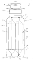
- a double-aerosol device 1 of the embodiment includes one outer container 11, two inner containers 12 and 13 stored in the outer container 11, a valve unit 14 provided in an upper portion of the outer container 11, and a discharger 15 provided in an upper portion of the valve unit 14.
- the outer container 11 of the embodiment includes a container body 111 that is a main portion and a sheet-shaped exterior material 112 that is mounted on an external surface of the container body 111.
- the container body 111 is a bottle container of which an entire surface is formed of a transparent resin (for example, PET).
- the container body 111 includes a bottom part 114 that is a circular shape in a plan view having a plurality (for example, the number of approximately 3 to 6) of protruding leg parts 113, a cylindrical body part 115 of which a cross section is circular, a shoulder part 116 having a shape of which a diameter is reduced upward, and a cylindrical neck part 117.
- the bottom part 114, the body part 115, the shoulder part 116, and the cylindrical neck part 117 are integrally (as a component) formed.
- the shape of the container body 111 is merely an example and is not limited thereto. For example, the shape thereof may not have the protruding leg part 113.
- the exterior material 112 is a cylindrical resin sheet (for example, a shrink film).
- the exterior material 112 is mounted on an outer periphery of the body part 115 in the container body 111.
- a material of the exterior material 112 is a transparent resin (for example, PE, PP, PVC, PS, and PET).
- Various types of information such as a trade name, a using method, and a design image are displayed (printed and the like) in the exterior material 112.
- a portion in which the information is displayed in the exterior material 112 is opaque.
- a transparent portion in which the display is not provided is secured in a position (in the example, in a position in which a second inner container 13 is seen in front of a first inner container 12) for visually recognizing the second inner container 13 in the exterior material 112.
- the transparent portion functions as an outside window part 118. That is, the second inner container 13 (specifically, a center portion in which a second joint member 132 is positioned in a second pouch 131 described below) is visually recognized from the outside through the outside window part 118.
- three rectangular outside window parts 118 are arranged in a vertical direction (up-down direction).
- the exterior material 112 is illustrated in a virtual line (two-dot chain line).
- a portion center portion in the inner containers 12 and 13 in the up-down direction
- the outside window part 118 may be formed in a form cutting out the exterior material 112.
- each of the inner containers 12 and 13 include pouches 121 and 131 that are bag bodies having a structure formed by bonding a peripheral portion of a sheet material, and joint members 122 and 132 that are fixed to communication ports (upper opening) thereof. Moreover, in Figs.
- the pouches 121 and 131 are illustrated in virtual lines (two-dot chain lines).
- a portion (a part of the joint members 122 and 132) which is hidden by the pouches 121 and 131 and content is also illustrated.
- a configuration in which the lower end portions of the inner containers 12 and 13 abut the upper surface of the bottom part 114 is exemplified, but the invention is not limited to the configuration.
- the lower end portions of the inner containers 12 and 13 may be configured not to abut the upper surface of the bottom part 114.
- a first content is stored in the first pouch 121 used for the first inner container 12. Furthermore, a second content different from the first content is stored in the second pouch 131 used for the second inner container 13.
- the first content and the second content are hair treatment compositions. More specifically, the first content and the second content are a first agent and a second agent that are used by mixing as a hair dye, decoloring agent, or dye remover.
- the first agent contains an alkaline agent and the second agent contains hydrogen peroxide.
- the second agent since oxygen is generated by decomposing the hydrogen peroxide, it is necessary for the oxygen generated in the second inner container 13 to escape to the outside of the second inner container 13.
- a space outside the inner container is not independent as the duplex can container. Thus, for example, when the first inner container 12 and the second inner container 13 are stored in the common outer container 11, oxygen transported to the outside of the second inner container 13 may penetrate into the first inner container 12.
- a multi-layered sheet material having high performance for blocking gas and liquid is used for the first pouch 121 used in the first inner container 12.
- an opaque sheet material having a multi-layered (for example, six layers) structure in which a metal foil sheet, a resin sheet, and the like are laminated is used for the first pouch 121.
- a thickness of the first pouch 121 may be approximately 70 ⁇ m to 150 ⁇ m. Since the pouch 121 is easily crushed with the discharge of the content and the content can be squeezed by making the thickness be 150 ⁇ m or less, a stable discharge amount can be easily obtained until the very end.
- the thickness of the aluminum layer may be 5 ⁇ m to 20 ⁇ m.
- a sheet material having a property (gas permeable) in which gas passes through but liquid does not pass through is used for the second pouch 131 used in the second inner container 13.
- a transparent sheet material having a single-layered or multi-layered structure using a resin sheet is used.
- a thickness of the second pouch 131 may be 70 ⁇ m to 150 ⁇ m for the same reason as that of the first pouch 121.
- polyester such as polyethylene may be used.
- the first pouch 121 is opaque, but the second pouch 131 can be transparent.
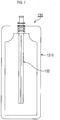
- An entire surface of the second pouch 131 can be transparent, but in the embodiment, as illustrated in Fig. 5 , opaque parts 139 are formed at both of the right and left portions.
- the opaque part 139 may be directly formed (printing and the like) on a sheet material configuring the second pouch 131 or may be formed on the pouch surface by bonding another sheet. That is, in the second pouch 131, the center portion is transparent other than at both of the right and left portions and the inside can be visually recognized in the center portion thereof.
- the first pouch 121 and the second pouch 131 are designed to be a common shape.
- outer shapes of the pouches 121 and 131 are substantially rectangular shapes.
- the pouches 121 and 131 have shapes in which both upper ends are formed being inclined linearly and are gradually narrowed upward.
- inner spaces (spaces in which the contents are stored) of the pouches 121 and 131 also have shapes in which both rectangular upper ends are formed being inclined linearly and welded, and are gradually narrowed upward.
- corner parts in outer shapes of the pouches 121 and 131 are round (arc shaped) so as not to cause interference with the outer container 11.
- angles of the inclined portions of both of the upper ends may be 30 degrees to 60 degrees with respect to the vertical direction.
- a linear portion is ensured in an upper end center portion of the inner space in a lateral direction (horizontal direction). This is because the upper end center portions (portions into which the joint members 122 and 132 are inserted) of the pouches 121 and 131 are easily welded in a state where the joint members 122 and 132 are inserted into the pouches 121 and 131 in a manufacturing process of the inner containers 12 and 13.
- a length of the linear portion may be 10 mm or greater.
- the length of the linear portion may be 35 mm or less (preferably 30 mm or less).
- the length of the linear portion in the upper end center of the inner space be, for example, 15 mm or greater and 35 mm or less.
- the lateral width of the inner space does not exceed 35 mm, such an effect may be obtained without forming the upper portion of the inner space to be narrowed (for example, even a usual rectangular shape).
- the lateral width of the inner space exceeds 35 mm, such an effect may be obtained by forming the upper portion of the inner space to be narrowed.
- the joint members 122 and 132 form flow passages for discharging the contents to the outside in the communication ports of the pouches 121 and 131 and are intended to hardly inhibit the flow of the contents in the inner space by bending of the pouches 121 and 131, and the like.
- shapes of the first joint member 122 used for the first inner container 12 and the second joint member 132 used for the second inner container 13 are different from each other.
- the invention is not limited to the embodiment and any one of the joint members may be used for both inner containers. That is, the joint members having the same shape may be used. According to the configuration in which the joint members having the same shape are used, it is possible to increase production efficiency compared to a case where the joint members having different shapes are used.
- the pouches 121 and 131 are crushed similarly, it is possible to easily grasp the remaining amount. Furthermore, for example, if viscosity and stickiness of the first content and the second content are substantially the same as each other, it is possible to easily discharge the first content and the second content at a substantially similar amount by using the same joint member.
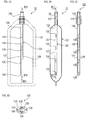
- the first joint member 122 includes a cylindrical head part 124 that forms an inside flow passage 123 in which the content passes through the communication port of the first pouch 121 and a rod-shaped part 125 that is inserted into the first pouch 121.
- the head part 124 and the rod-shaped part 125 are integrally molded with a resin.
- a slit 126 passing through the front and back sides is linearly formed in the rod-shaped part 125 in the vertical direction (up-down direction).
- the rod-shaped part 125 has a shape in which two parallel rods 127 and 128 are disposed on the right and left with a gap therebetween.
- connecting parts 129 connecting the rods 127 and 128 are provided in a plurality of locations (in the example, four locations having a constant interval) having a gap each other between two rods 127 and 128. That is, the rod-shaped part 125 has an entire ladder shape.
- a thickness dimension of the connecting part 129 is shorter than thickness dimensions of two rods 127 and 128 respectively so as not to close an open flow passage (flow passage formed between the slit 126 and the inner surface of the pouch) formed by the slit 126 (see Fig. 3B ).
- a cross-sectional shape (cross-sectional shape of the rod-shaped part 125 in an axial direction) of a portion in which the connecting part 129 is provided becomes an H shape (see Fig. 3D ).
- the second joint member 132 includes a cylindrical head part 134 forming an inside flow passage 133 in which the content passes through the communication port of the second pouch 131 and a rod-shaped part 135 that is inserted into the inside of the second pouch 131.
- the head part 134 and the rod-shaped part 135 are integrally molded by a resin.
- a cross section of the rod-shaped part 135 orthogonal in the axial direction is a substantially oval shape (specifically, a shape in which corner portions of a diamond shape are arc shapes) (see Fig. 4C ).
- a lateral width dimension (length of a width in a direction along the surface of the second pouch 131 and in a lateral direction in Fig. 4C ) is longer than a thickness dimension (length of a width in a direction orthogonal to the surface of the second pouch 131 and in the vertical direction in Fig. 4C ).
- the thickness dimension of the rod-shaped part 135 is designed to match with a thickness dimension of a welding portion having a cross section of the diamond shape in a portion which is a lower portion of the head part 134 and in which the pouch 131 is welded.
- the pouch 131 is likely to be along the welding portion of the joint member 132 (unlikely to lift from the welding portion) and the welding is easily performed.
- the cross section of the rod-shaped part 135 is the oval shape in which the thickness dimension is shorter than the lateral width dimension, it is possible to reduce a gap (space in which the content is likely to remain) formed at both right and left sides of the rod-shaped part 135 in a state where almost all content is discharged. Thus, the amount of the content remaining in the pouch 131 is reduced.
- a linear slit 136 is formed in a surface (surface on a left side in Fig. 4B and hereinafter, referred to as "inwardly facing surface”) facing a side of the first inner container 12 in the vertical direction (up-down direction) to the lower end.
- a depth of the slit 136 becomes deeper in a stepwise fashion in an upper portion thereof.
- a through hole 137 passing through a surface (surface on a right side in Fig. 4B and hereinafter, referred to as "outwardly facing surface”) opposite to the inwardly facing surface in the uppermost end of the slit 136 is formed.
- a depth of the slit 136 may be 20% to 50% of the thickness dimension of the rod-shaped part 135. Furthermore, as another expression, the depth of the slit 136 may be 0.5 mm or greater and a thickness dimension of a remaining portion (a portion to be thin enough to deepen the slit 136) by the slit 136 may be 1.5 mm or greater. Furthermore, from the viewpoint of hardly biting the pouch 131 in the slit 136, for example, the lateral width dimension of the slit 136 may be 0.5 mm to 3 mm. Furthermore, the width dimension of the slit 136 may be a shape widening upward in a stepwise fashion. Furthermore, the shape is not limited to the stepwise fashion and may be obliquely widened (deepened) upward.
- the slit such as the inwardly facing surface is not formed in the outwardly facing surface and a concave part 138 is formed in the lower end portion.
- the concave part 138 is a part that becomes a gate when molding the joint member 132 with a resin and has a concave shape so as not to damage the pouch 131 due to protrusion of burr.
- the lower end portion of the rod-shaped part 135 is the gate because the rod-shaped part 135 is long and rigidity thereof is high.
- a color of the outwardly facing surface is different from a color (opaque color, and white in the embodiment) of the second content and displays a color (yellow in the embodiment) that can be easily visually recognized.
- a display function is realized by coloring the material itself of the second joint member 132 yellow. Therefore, in the example, a portion other than the outwardly facing surface is yellow.
- the color is not limited to the configuration.
- an exterior material (for example, seal) of a color that can be visually recognized may be mounted on at least the portion of the outwardly facing surface in the second joint member 132 formed by a color material other than the color that can be easily visually recognized.
- the color of the outwardly facing surface is merely an example and is not limited to yellow, and, for example, may be red.
- the lateral width of the rod-shaped part 135 of the second joint member 132 is designed to be slightly greater than that of the rod-shaped part 125 of the first joint member 122. This is because the outwardly facing surface is likely to be visually recognized by increasing an area of the outwardly facing surface. That is, the outwardly facing surface functions as a gauge for grasping the remaining amount of second content from the outside of the outer container 11.
- the valve unit 14 includes two valves respectively corresponding to two inner containers 12 and 13, valve holders fixing two valves in parallel, mountain covers fixing the valve holders to an opening part of the outer container 11, and the like.
- a first valve is connected to the upper end portion of the first joint member 122 and opens and closes a discharge flow passage of the content stored in the first pouch 121.
- the first joint member 122 communicates with the inside of the first pouch 121 and the first valve.
- a second valve is connected to the upper end portion of the second joint member 132 and opens and closes a discharge flow passage of the content stored in the second pouch 131.
- the second joint member 132 communicates with the inside of the second pouch 131 and the second valve.
- Each valve includes vertically movable stems 141 and 142, and the flow passage is opened by pressing the stems 141 and 142 down.
- the configuration itself of such a valve unit 14 is known, the structure thereof is simply illustrated and the detailed description thereof will be omitted.
- the configuration described here is an example and may be replaced by another configuration having a similar function.
- a stem of a type in which the flow passage is opened by inclining the stem may be used instead of the stem of the type in which the flow passage is opened by pressing the stem down.
- the gap between the stems 141 and 142 may be designed to be a length of 50% or greater (preferably a length of 60% or more) of the maximum value (bulged width before discharging the content) of the thickness dimension of the pouches 121 and 131.
- the amount of the contents stored in the inner containers 12 and 13 may be 90% or less of a full capacity (storable maximum value).
- the full capacity described here means a capacity immediately before (limit full) the water overflows by a restoring force of the pouches 121 and 131 after continuously injecting the water into vacant inner containers 12 and 13.
- a space inside of the outer container 11 and outside of the inner containers 12 and 13 is sealed by the valve unit 14 and propellant (for example, compressed gas) is filled in the sealed space.
- propellant for example, compressed gas
- Two pouches 121 and 131 are always pressed by the propellant and are configured such that the contents are discharged to the outside by compressing the inner containers 12 and 13 by the pressure of the propellant.
- the propellant is filled in the outer container 11.
- the mountain cover is in a state of being slightly apart from the outer container 11.
- the length of the inner containers 12 and 13 in the up-down direction is designed such that the inner containers 12 and 13 are in a state of abutting and being mounted on the upper surface (bottom surface) of the bottom part 114 in the outer container 11 (container body 111).
- the length of the inner containers 12 and 13 in the up-down direction is a length that is obtained by adding the length of the pouches 121 and 131 in the up-down direction and the length of the joint members 122 and 132 protruding from the upper portion of the pouches 121 and 131 in the up-down direction.
- the discharger 15 has an inside flow passage that merges and discharges the first content and the second content discharged from the stems 141 and 142 from a nozzle 151.
- the discharger 15 is vertically movable and simultaneously presses two stems 141 and 142 by pressing the upper surfaces thereof downward.
- the first valve and the second valve are simultaneously opened and the contents are simultaneously discharged from the inner containers 12 and 13.
- the configuration itself of such a discharger 15 is known, the configuration is simply illustrated and detailed description will be omitted.
- two inner containers 12 and 13 are respectively filled with the contents.
- the first content and the second content are simultaneously discharged. Specifically, the contents are respectively discharged to the outside in the pouches 121 and 131. At this time, the contents present on the upper side are sequentially discharged in the inner spaces of the pouches 121 and 131.
- the outwardly facing surface of the rod-shaped part 135 of the joint member 132 is gradually exposed from the upper portion according to the reduction of the second content.
- the outwardly facing surface of the exposed rod-shaped part 135 as described above can be visually recognized through the outside window part 118 from the outside of the outer container 11 so that it is possible to grasp the remaining amount of the second content.
- the first content and the second content are designed to be discharged at a constant ratio (1:1 in the embodiment) and to be able to be used up simultaneously.
- a constant ratio (1:1 in the embodiment)
- the double-aerosol device 1 of the embodiment includes two inner containers 12 and 13 which respectively store the hair treatment compositions (first agent and second agent) that are used by mixing as the hair dye, the decoloring agent, or the dye remover, and the outer container 11 storing the two inner containers 12 and 13.
- the double-aerosol device 1 is configured to discharge the contents (hair treatment compositions) to the outside by contracting the inner containers 12 and 13 by the pressure of the propellant.
- the outer container 11 is configured such that at least a part of the inside of the outer container 11 can be visually recognized.
- the remaining amount of the contents can be visually recognized.
- the double-aerosol device 1 of the embodiment since the inside of the outer container 11 is visually recognized, it is possible to recognize the remaining amount of the contents.
- the inner containers 12 and 13 store the contents in the pouches 121 and 131. Then, a transparent portion is formed in the second pouch 131 and the inside thereof can be visually recognized. Thus, it is possible to easily grasp the remaining amount of the contents. Specifically, in the configuration in which the first inner container 12 and the second inner container 13 are stored in the common outer container 11, since the space outside the inner container is not independent as the duplex can container, a high cutoff performance is required in the inner containers 12 and 13 to avoid contact and reaction of the first content and the second content such as described in paragraph 0019.
- the pouch is a structure that is provided by bonding the peripheral portion of the sheet material and can be formed by using a sheet material of a multi-layered structure (for example, six layers) in which a degree of freedom of the material is high, it is possible to realize a high blocking performance. Furthermore, if it is the pouch, since a surface close to a plane is widely formed, it is possible to increase the visibility. In addition, since the opaque parts 139 are formed in both right and left portions of the second pouch 131, the content easily remaining (technically difficult to discharge) in the end portion of the pouch 131 is not visually recognized. So, it is possible to avoid grasping the remaining amount by mistake.
- the inner containers 12 and 13 include the joint members 122 and 132 extending from the communication ports discharging the contents to the inside of the pouches 121 and 131.
- the joint members 122 and 132 extending from the communication ports discharging the contents to the inside of the pouches 121 and 131.
- the content stored in the upper portion of the inner space is closer to the center than that of a shape in which the upper portion of the inner space is not narrowed.
- the content of the upper portion in the inner space is positioned closer to the joint member 122 and is easily discharged, it is possible to reduce the remaining amount of the content in the upper portion of the inner space.
- the contents in the upper portions of the inner spaces are initially discharged and the contents are likely to sequentially discharge from the upper side by the flowing thereof, the contents stored in the pouches 121 and 131 are likely to be sequentially reduced from the upper portion in the inner spaces of the pouches 121 and 131.
- the second joint member 132 since the lateral width dimension is elongated and the outwardly facing surface that is visually recognized as the gauge is widely formed, it is possible to increase the visibility of the remaining amount. Specifically, since the slit 136 is formed in the inwardly facing surface in the rod-shaped part 135 and the slit is not formed in the outwardly facing surface, the second content more easily flows on the side of the inwardly facing surface than on the side of the outwardly facing surface. Thus, the outwardly facing surface is unlikely to be hidden in the second content and the color of the outwardly facing surface is likely to be visually recognized.
- the shapes of the first joint member 122 and the second joint member 132 are different from each other, a discharging ratio of the first content and the second content of which the stickiness is different can be closer to a desirable ratio.
- the width of the slit 126 formed in the rod-shaped part 125 is wider than the width of the slit 136 formed in the rod-shaped part 135 (an area of the formed flow passage is large).
- the discharge amount of the first content of which the stickiness is ordinarily higher than that of the second content can be closer to the discharge amount of the second content.
- the invention may be configured as follows.
- the outer container 11 In order to visually recognize the remaining amount of the content from the outside of the outer container 11, it is necessary for at least a part of the outer container 11 to have a light-transmitting property (transparent or semitransparent).
- the outer container 11 of the configuration in which the exterior material 112 is mounted on the container body 111 formed by a transparent material and the inside is visually recognized from the outside window part 118 provided in the exterior material 112 is exemplified, but the invention is not limited to the embodiment.
- the shape, the size, the position, the number, and the like of the outside window part are not specifically limited as long as the remaining amount of the content can be visually recognized.
- one container body 111 in which characters, drawings, and the like are directly formed (printing and the like) may be the outer container without using the exterior material 112.
- an entire surface may be transparent as the outer container without forming the opaque portion.
- the inner containers 12 and 13 in which the remaining amount of the contents can be visually recognized by making the center portion of the second pouch 131 other than the both right and left portions be transparent is exemplified ( Fig. 5 ).
- the invention is not limited to such a configuration.
- the shape, the size, the position, the number, and the like of the transparent portion in the second pouch are not specifically limited as long as the remaining amount of the content can be visually recognized.
- an opaque part 139A covering the rod-shaped part 135 may be formed in the center portion in addition to the opaque parts 139 in the both right and left portions.
- the content easily remaining (technically difficult to discharge) in the both sides of the rod-shaped part 135 is not visually recognized while visually recognizing the content present only by both right and left sides of the rod-shaped part 135 and it is possible to avoid grasping the remaining amount by mistake.
- the sheet material of one side (side of the first inner container 12) configuring the second pouch is opaque and a transparent portion may be provided in the other sheet material.
- a transparent portion may be provided in the other sheet material.
- the transparent portion is not limited to a part of the second pouch and an entire surface of the second pouch may be transparent.
- the invention is not limited to the configuration in which at least a part of the pouch is transparent.
- a degree of the deformation of the pouch can be visually recognized and the remaining amount of the content may be grasped based on the degree of the deformation thereof. Since orientation of the pouch to be deformed is specified compared to another bag-shaped container, there is an advantage that the remaining amount is easily grasped based on the degree of the deformation.
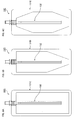
- the pouches 121 and 131 having the shape of which the both upper ends of the inner space are inclined and which is linearly formed are exemplified, but the invention is not limited to the embodiment and, for example, may have a shape as illustrated below. Moreover, the shape as illustrated below may be applied to one of the first content and the second content or may be applied to both sides. Furthermore, the second joint member 132 is exemplified as the flow passage member, but is merely an example and the invention is not limited to the embodiment.
- both upper ends of the inner space are not in a linear shape but may be in an inwardly recessed shape (in the example, an arc shape).
- the shape illustrated in Fig. 7 has more prominent features that the lateral width is narrower as the upper position in the inner space. According to the shape illustrated in Fig. 7 , it is possible to improve the effect that the remaining amount of the content is reduced in the upper portion of the inner space and to improve the effect that the content is easily discharged sequentially from the upper side of the inner space.
- the upper portion of the outer shape of the pouch may be narrow to match the shape of the inner space.
- the lateral width of the inner space may be a constant (in the example, rectangular shape) shape.
- the lower portion of the inner space may be gradually narrowed downward.
- the content (first content in the embodiment described above) having a high viscosity easily remains in the lower portion of the inner space, and it is possible to reduce the remaining amount by narrowing the lower portion.
- the example may be applied to a part (the first pouch 121 in the embodiment described above) of a plurality of pouches.
- an inwardly recessed shape for example, an arc shape
- a shape in which the upper portion of the inner space is gradually narrowed upward and the lower portion is gradually narrowed downward may be provided.
- an inwardly recessed shape for example, an arc shape
- an inwardly recessed shape may be provided instead of the shape in which the both upper end portions and the both lower end portions of the inner space are formed in an inclined linear shape.
- the lower portion of the inner space may be a shape protruding downward in an arc shape. Even in this case, the same effect (effect that the content is unlikely to remain in the lower portion) as that of the configuration of Fig. 8B is obtained.
- the inner space may be divided into a plurality of chambers (in the example, two up and down chambers).
- the discharge amount of the content is easily adjusted for each chamber and it is possible to sequentially discharge from the upper side.
- the side portion of the inner space may be a constricted shape.
- a shape that is gradually narrowed upward may be provided.
- a shape that is gradually narrowed downward may be provided.
- a shape that is gradually narrowed upward and downward may be provided.
- a restoring force (force acting for discharging the content) in the upper side is greater than a restoring force in the lower side and the content can be easily sequentially discharged from the upper portion by making the inner space of the upper side be greater than the inner space of the lower side.
- the inner space is divided into a plurality of chambers (in the example, three up and down chambers) and a shape in which chambers adjacent to each other communicate with each other by one end portion (in the example, side to be alternated between right and left) may be provided.
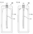
- the dividing direction is not limited to up and down, and for example, as a second pouch 131L of a second inner container 13L illustrated in Fig. 11B , the inner space is divided into a plurality of chambers in right and left, and the chambers adjacent to each other may have shapes which communicate with each other by one end portion (in the example, the lower end).
- the flow of the content in the inner space is regulated, deviation of the aspect in which the content is discharged hardly occurs.
- the inside of the inner space may be partially welded.
- the inside (in the example, both upper ends) of the rectangular inner space may be partially welded in a point shape.
- two positions are respectively welded in right and left, but one position is welded in right and left, and more positions may be welded than the example.
- the inside (in the example, both upper ends) of the rectangular inner space may be partially welded in a linear shape.
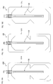
- the outer shape of the pouch may be changed depending on the shape of the inner space of the pouch. For example, as illustrated in Fig. 8B , if the lower portion of the inner space has the shape gradually narrowed downward, the outer shape of the pouch may also have the shape gradually narrowed downward. In this case, it is possible to hardly interfere with the outer container 11.
- a first pouch 121A of a first inner container 12A illustrated in Fig. 13A an outer shape of a shape (shape gradually narrowed upward and downward, and in which four corners of a rectangular shape are cut) in which the both upper ends and the both lower ends are linearly inclined may be provided.
- a width of a seal part (peripheral edge bonding the seal materials each other) of the upper portion in the pouch 121A may be greater (area of the seal part is large) than the width of the seal part of the lower portion.
- the seal part of the upper portion is harder than the seal part of the lower portion, and even when inverted falling (falling with the head part 124 being directed downward), the pouch 121A is hardly crushed and it is possible to maintain the same state of the pouch 121A as that before falling thereof. Furthermore, as illustrated in Fig. 13B , it is difficult for the upper portion of the pouch 121A to be widened in the thickness direction (thickness is narrowed) compared to the lower portion of the pouch 121A. Thus, an inner volume in the upper portion of the pouch 121A is smaller than an inner volume in the lower portion of the pouch 121A. As a result, the content is always easily filled in a constant balance (state where the lower side is large). Thus, when using the pouch 121A having such a shape for the first inner container and the second inner container, deviation of the discharging ratio of the first inner container and the second inner container can hardly occur.
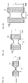
- a joint member 122B of a first inner container 12B illustrated in Figs. 14A to 14C has basically the same shape as that of the first joint member 122 of the embodiment described above.
- a thickness dimension (length of the width in a direction orthogonal to the surface of the pouch 121 and a lateral direction in Fig. 14B ) of the lower end portion in a rod-shaped part 125B is formed longer than that of a portion other than the lower end portion.
- protrusion parts 127C and 128C protruding further downward than the connecting part 129 of the lowermost end are formed in the lower end of rods 127B and 128B.
- the protrusion parts 127C and 128C have the same shape and as illustrated in Fig. 14E , protrude on both sides (both right and left sides in the lateral direction in Figs. 14B and 14E ) in the thickness direction compared to a portion other than the protrusion parts 127C and 128C in the rods 127B and 128B. In such a shape, it is possible to hardly close the pouch 121 in the lower end portion of the rod-shaped part 125B and to easily pump out the content accumulated in the lower portion in the inner space of the pouch 121.
- a thickness dimension of the upper end portion (connection part to the head part 124 and a portion positioned in the uppermost portion in the inner space of the pouch 121) in the rod-shaped part 125B is formed to be shorter than that of a portion other than the upper end portion.
- upper end portions 127D and 128D of the rods 127B and 128B have the same shape as each other and, as illustrated in Fig. 14F , are further inwardly (center line side) recessed in both end sides in the thickness direction than a portion other than the upper end portions 127D and 128D in the rods 127B and 128B.
- a thickness T of a portion other than the protrusion parts 127C and 128C, and the upper end portions 127D and 128B in the rods 127B and 128B is constant (see Figs. 14E and 14F ). Furthermore, a gap (lateral width dimension of a slit 126B) D between the rods 127B and 128B is also constant (see Fig. 14D ). If the thickness of the pouch 121 is in a range of 70 ⁇ m to 150 ⁇ m, a ratio T/D between the thickness T of the rods 127B and 128B and the gap D may be 1.0 to 3.0. As illustrated in Fig.
- the ratio T/D is less than 1.0, the pouch 121 is easily closed and the content is hardly discharged. Furthermore, as illustrated in Fig. 15C , the ratio T/D is greater than 3.0 and the pouch 121 is hardly closed, but the amount of the content remaining between the rods 127B and 128B is increased. In contrast, if the ratio T/D is 1.0 to 3.0, as illustrated in Fig. 15B , it is possible to reduce the amount of the content remaining between the rods 127B and 128B while preventing the blocking of the pouch 121.
- Fig. 16 illustrates test results in cases where the thickness T of the rods 127B and 128B and the gap D are different.
- 40 g of the first agent was filled in the first pouch 121 having the thickness of 121 ⁇ m and 40 g of the second agent was filled in the second pouch 131 having the thickness of 104 ⁇ m. Then, a case where 30 g or more of 40 g of the content can be discharged with discharge amount of 2 g to 15 g or more for every three seconds was evaluated as good and a case where the discharge amount cannot be discharged was evaluated as permissible. As illustrated in Fig.
- the thickness T of the portion other than the protrusion parts 127C and 128C and the upper end portions 127D and 128D is constant in the rods 127B and 128B, and the gap D between the rods 127B and 128B is also constant.
- the effect described above is obtained in most portions in the rod-shaped part 125B by designing the ratio T/D of the portion to be in a range of 1.0 to 3.0, a high effect can be obtained as a result.
- the shape of the joint member is not specifically limited and the effect described above can be obtained in the portion as long as the portion in which the ratio T/D is in the range of 1.0 to 3.0 also partially exists and, specifically, the effect can be increased as the ratio of the portion is increased.
- Figs. 14A to 14F may be applied to one of the first joint member and the second joint member or may be applied to both sides.
- the pouch 121 of the embodiment described above is exemplified, but is merely an example, and is not limited to the embodiment.
- the position or the number of the slits may be changed.
- the slits may be formed on both surfaces of the rod-shaped part (for example, H type cross section) and the slits may be formed in a corner part of the rod-shaped part (for example, T-shaped cross section, cross-shaped cross section, and star-shaped cross section).
- the slit may be formed around the rod-shaped part in a spiral shape.
- the flow passage member is not limited to the configuration in which the opening flow passage is formed by the slit and may be a configuration (tube) having an inner flow passage.
- a hole may be formed in the upper portion so that the content is preferentially discharged from the upper portion rather than the lower portion of the inner space.
- intervals of the holes may be decreased as the holes are made in the upper portion or the size of the holes may be increased as the holes are made in the upper portion.
- the hole in the shape having the constriction, since the content easily remains in the upper portion of the constriction, the hole may be formed in a position corresponding to the upper portion of the constriction. Furthermore, the same effect is obtained by widening the width dimension of the slit or by deepening the depth of the slit instead of the hole of the tube.
- the length of the flow passage member may be a length that makes a gap with a bottom side of the pouch become as small as possible.
- the flow passage member having the same configuration may be used in a plurality of pouches.
- the flow passage member may not be used in at least a part of the plurality of pouches.
- the pouch is not limited to the configuration in which the entire periphery thereof is sealed and, for example, one sheet is folded, and three sides of the sheet may be sealed.
- the pouch may be a gusset type having a "gusset" in the side portion and the like.
- the content is not limited to the first agent and the second agent of the two-agent type hair dye, decoloring agent, or dye remover, and, for example, may be a hair dye, a treatment agent, and the like.
- the hair dye includes acidic hair dye, direct hair dye, a temporal coloring agent, and the like.
- the number of the inner containers is not limited to two and may be three or more.
- three-type hair treatment compositions configuring three agent-type hair dye, decoloring agent, or dye remover are separately stored and may be discharged by combining them.
- one inner container is formed and the hair treatment composition (for example, one agent-type medicine) used as it is without being mixed may be stored.
- one (in the embodiment described above, for example, the second inner container) among a plurality of contents is directly stored in the outer container 11 without storing in the pouch and may be sucked by a tube 232.
- the propellant is filled in a remaining space in the outer container 11.
- a liquid surface of the content directly stored in the outer container 11 can be visually recognized from the outside of the outer container 11, it is possible to relatively accurately grasp the remaining amount of the content.
- a configuration in which one inner container 32 is stored in the other inner container 33 may be provided.
- the inner container 33 of the outside is visually recognized but the inner container 32 of the inside is not visually recognized, it is possible to grasp the remaining amount of the content based on a degree of deformation of one inner container 33.
- at least a part of the inner container 33 of the outside is transparent and the inside thereof can be also visually recognized.
- the content could be discharged in the thickness range of 70 ⁇ m to 150 ⁇ m described above without a problem; specifically, a good result was obtained in a range of 100 ⁇ m to 150 ⁇ m, and a further good result was obtained in a range of 100 ⁇ m to 130 ⁇ m.
Landscapes
- Engineering & Computer Science (AREA)
- Mechanical Engineering (AREA)
- Chemical & Material Sciences (AREA)
- Dispersion Chemistry (AREA)
- Containers And Packaging Bodies Having A Special Means To Remove Contents (AREA)
- Package Specialized In Special Use (AREA)
- Packages (AREA)
- Nozzles (AREA)
- Medicinal Preparation (AREA)
- Cosmetics (AREA)
- Bag Frames (AREA)
Claims (8)
- Eine Doppel-Aerosol-Vorrichtung (1) umfassend:eine Vielzahl an inneren Behältern (12; 13), die eine Vielzahl an Haarbehandlungsgemischarten separat aufnehmen, welche durch Mischen als Haarfärbemittel, Entfärbungsmittel oder Färbemittelentferner verwendet werden; undeinen äußeren Behälter (11), in dem die Vielzahl an inneren Behältern (12; 13) aufgenommen sind,wobei die Haarbehandlungsgemische durch Kontrahieren der Vielzahl an inneren Behältern (12; 13) durch einen Treibmitteldruck nach außen abgegeben werden,wobei der äußere Behälter (11) so gestaltet ist, dass zumindest ein Teil des Inneren des äußeren Behälters (11) sichtbar ist, um so die verbleibenden Mengen der Haarbehandlungsgemische zu bestätigen, undwobei jeder der inneren Behälter (12; 13) einen Beutel (121; 131), welcher die Haarbehandlungsgemische aufnimmt, und ein Strömungsdurchgangsbauteil (122; 132) umfasst, welches an einer Verbindungsöffnung des Beutels (121; 131) befestigt ist und einen in den Beutel (121; 131) eingeführten stabförmigen Teil (125; 135) aufweist, ist,dadurch gekennzeichnet, dass der stabförmige Teil (125; 135) wenigstens eines der Vielzahl an inneren Behältern (12; 13) zwei parallele, durch eine Vielzahl an Verbindungsteilen (129) verbundene Stäbe (127, 128) und Vorsprungsteile (127C, 128C) aufweist, welche an dessen unterem Endabschnitt ausgebildet sind, wobei die Vorsprungsteile (127C, 128C) eine Breitendimension in der orthogonal zur Oberfläche des Beutels (121; 131) verlaufenden Richtung größer als eine Breitendimension der parallelen Stäbe (127, 128) mit Ausnahme des unteren Endabschnitts aufweisen.
- Doppel-Aerosol-Vorrichtung (1) nach Anspruch 1,
wobei ein oberer Abschnitt eines Innenraums von mindestens einem der Vielzahl an inneren Behältern (12; 13) eine sich nach oben verengende Form aufweist. - Doppel-Aerosol-Vorrichtung (1) nach Anspruch 1 oder 2, wobei der Beutel (121; 131) mindestens eines der Vielzahl an inneren Behältern (12; 13) einen transparenten Abschnitt aufweist und so gestaltet ist, dass ein Innenabschnitt des Beutels (121; 131) visuell erkennbar ist.
- Doppel-Aerosol-Vorrichtung (1) nach einem der Ansprüche 1 bis 3, wobei die Vielzahl an inneren Behältern (12; 13) einen ersten inneren Behälter (12) und einen zweiten inneren Behälter (13) umfasst, wobei der erste innere Behälter (12) und der zweite innere Behälter (13) parallel in dem äußeren Behälter (11) aufgenommen sind, wobei der zweite innere Behälter (13) den Beutel (131) mit einem transparenten Abschnitt umfasst und so gestaltet ist, dass mindestens ein Abschnitt einer nach außen weisenden Oberfläche des in den Beutel (131) eingesetzten stabförmigen Teils (135) visuell erkannt werden kann, und wobei die nach außen weisende Oberfläche eine Oberfläche ist, die einer nach innen weisenden Oberfläche des stabförmigen Teils (135) gegenüberliegt, welche einer Seite des ersten inneren Behälters (12) zugewandt ist.
- Doppel-Aerosol-Vorrichtung (1) nach Anspruch 4, wobei die Vielzahl an inneren Behältern (12; 13) einen ersten inneren Behälter (12), der ein erstes Mittel speichert, welches ein alkalisches Mittel enthält, und einen zweiten inneren Behälter (13) umfasst, der ein zweites Mittel speichert, welches Wasserstoffperoxid enthält, wobei ein lichtundurchlässiges Folienmaterial für einen ersten Beutel (121) in dem ersten inneren Behälter (12) verwendet wird, und wobei ein durchsichtiges Folienmaterial für einen zweiten Beutel (131) in dem zweiten inneren Behälter (13) verwendet wird.
- Doppel-Aerosol-Vorrichtung (1) nach einem der Ansprüche 1 bis 5, wobei die zwei parallelen Stäbe (127, 128) mit einem Spalt zwischen parallel diesen angeordnet sind, und wobei die Vielzahl an Verbindungsteilen (129) an einer Vielzahl an Stellen vorgesehen sind, welche einen Abstand voneinander haben.
- Doppel-Aerosol-Vorrichtung nach Anspruch 6, wobei eine Breite eines sich von dem hervorstehenden Teil (127C, 128C) unterscheidenden Abschnitts des stabförmigen Teils (125) konstant ist, und wobei ein Verhältnis zwischen dieser konstanten Breite und einer Breite eines Spalts zwischen den beiden Stäben (127, 128) 1,0 bis 3,0 beträgt.
- Doppel-Aerosol-Vorrichtung (1) nach einem der Ansprüche 1 bis 7, wobei der Beutel (121; 131) von mindestens einem der Vielzahl an inneren Behältern (12; 13) einen transparenten Abschnitt umfasst und so gestaltet ist, dass ein Inneres des Beutels (121; 131) visuell erkannt werden kann, und wobei sowohl eine rechte als auch eine linke Seite des Beutels (121; 131) lichtundurchlässig sind.
Applications Claiming Priority (2)
| Application Number | Priority Date | Filing Date | Title |
|---|---|---|---|
| JP2012141093 | 2012-06-22 | ||
| PCT/JP2013/066955 WO2013191248A1 (ja) | 2012-06-22 | 2013-06-20 | 二重エアゾール装置 |
Publications (3)
| Publication Number | Publication Date |
|---|---|
| EP2865610A1 EP2865610A1 (de) | 2015-04-29 |
| EP2865610A4 EP2865610A4 (de) | 2016-03-02 |
| EP2865610B1 true EP2865610B1 (de) | 2020-12-30 |
Family
ID=49768841
Family Applications (1)
| Application Number | Title | Priority Date | Filing Date |
|---|---|---|---|
| EP13807225.1A Not-in-force EP2865610B1 (de) | 2012-06-22 | 2013-06-20 | Doppelaerosolvorrichtung |
Country Status (8)
| Country | Link |
|---|---|
| US (1) | US9533819B2 (de) |
| EP (1) | EP2865610B1 (de) |
| JP (1) | JP6214531B2 (de) |
| KR (1) | KR101634260B1 (de) |
| CN (1) | CN104507826B (de) |
| SG (1) | SG11201408461XA (de) |
| TW (1) | TWI519454B (de) |
| WO (1) | WO2013191248A1 (de) |
Families Citing this family (14)
| Publication number | Priority date | Publication date | Assignee | Title |
|---|---|---|---|---|
| JP6051107B2 (ja) * | 2013-05-31 | 2016-12-27 | 東洋エアゾール工業株式会社 | エアゾール容器用肩カバー |
| KR101827780B1 (ko) * | 2013-05-31 | 2018-02-09 | 도요 에어로졸 고교 가부시키가이샤 | 에어로졸 용기용 어깨 커버 |
| JP6051106B2 (ja) * | 2013-05-31 | 2016-12-27 | 東洋エアゾール工業株式会社 | エアゾール容器用肩カバー |
| FR3016870A1 (fr) * | 2014-01-27 | 2015-07-31 | Lindal France Sas | Dispositif de distribution a deux voies destine a fermer un flacon |
| EP3192749B1 (de) | 2015-04-24 | 2019-12-11 | Toyo Aerosol Industry Co., Ltd. | Element zur reduzierung von restmengen |
| CN117017797A (zh) | 2015-12-28 | 2023-11-10 | 花王株式会社 | 气溶胶型染发用或毛发脱色用化妆品 |
| JP7236207B2 (ja) | 2015-12-28 | 2023-03-09 | 花王株式会社 | エアゾール型染毛用又は毛髪脱色用化粧品 |
| JP6856993B2 (ja) * | 2016-09-08 | 2021-04-14 | 株式会社ダイゾー | 吐出容器 |
| JP6795946B2 (ja) * | 2016-10-14 | 2020-12-02 | 株式会社ダイゾー | 吐出容器 |
| JP6887236B2 (ja) * | 2016-10-14 | 2021-06-16 | 株式会社ダイゾー | 吐出容器 |
| US10945507B2 (en) | 2018-07-26 | 2021-03-16 | Cecelia Ann Mims | Method and apparatus for mixing beauty products |
| KR102074965B1 (ko) * | 2018-08-27 | 2020-02-07 | 주식회사 새롬코스메틱 | 공기소통 구멍이 생성된 포장팩 및 그 제작방법 |
| JP7610240B2 (ja) * | 2019-09-06 | 2025-01-08 | ホーユー株式会社 | 毛髪化粧料用品 |
| CN114212391B (zh) * | 2022-02-21 | 2022-05-03 | 河北华油天然气有限责任公司 | 气体泄漏检测气雾剂罐及气体泄漏检测方法 |
Family Cites Families (21)
| Publication number | Priority date | Publication date | Assignee | Title |
|---|---|---|---|---|
| BE639762A (de) * | 1962-11-16 | |||
| US3521792A (en) * | 1968-04-01 | 1970-07-28 | Dow Chemical Co | Dispensing actuator for component pressure cans |
| US3709437A (en) * | 1968-09-23 | 1973-01-09 | Hershel Earl Wright | Method and device for producing foam |
| FR1591250A (de) * | 1968-11-05 | 1970-04-27 | ||
| FR2697233B1 (fr) * | 1992-10-22 | 1995-01-27 | Lir France Sa | Distributeur à dosage variable pour produits fluides. |
| US5634571A (en) * | 1995-06-07 | 1997-06-03 | Innavision Services, Inc. | Apparatus for dispensing two sprayable substances in a user selectable ratio |
| JP3077135B2 (ja) | 1996-01-31 | 2000-08-14 | 花王株式会社 | 吐出容器 |
| JP2000327053A (ja) * | 1999-05-17 | 2000-11-28 | Toyo Aerosol Ind Co Ltd | 二重エアゾール容器 |
| JP2001122364A (ja) | 1999-10-27 | 2001-05-08 | Hoyu Co Ltd | 二重エアゾール容器 |
| US7036685B1 (en) * | 2002-06-17 | 2006-05-02 | Green Ronald D | Multi-valve delivery system |
| US7967220B2 (en) | 2002-09-13 | 2011-06-28 | Bissell Homecare, Inc. | Manual sprayer with dual bag-on-valve assembly |
| US6971555B1 (en) * | 2003-04-28 | 2005-12-06 | Hak Ghun | Apparatus for dispensing decontamination fluids |
| JP2004337582A (ja) * | 2003-10-27 | 2004-12-02 | Tatsuo Okazaki | 殺菌液保存方法及び殺菌用容器並びにこれに用いられる開閉弁付きノズル |
| JP4332444B2 (ja) * | 2004-02-17 | 2009-09-16 | 東洋製罐株式会社 | 染毛剤における二重構造エアゾール缶容器及びエアゾール缶容器に収納される内装パウチ |
| US20070241133A1 (en) | 2006-04-17 | 2007-10-18 | The Procter & Gamble Company | Container visible package |
| US7875001B2 (en) * | 2008-02-25 | 2011-01-25 | Americo Michael Minotti | Multi medication nasal spray device and method |
| JP5952739B2 (ja) * | 2010-10-29 | 2016-07-13 | 株式会社ダイゾー | 複数液吐出用エアゾール容器、複数液吐出エアゾール製品およびそれに用いられる内部容器 |
| WO2012073361A1 (ja) * | 2010-12-02 | 2012-06-07 | 東洋エアゾール工業株式会社 | 複数液分配用のエアゾール装置 |
| JP6077737B2 (ja) * | 2011-10-07 | 2017-02-08 | 株式会社ダイゾー | 二重エアゾール製品 |
| WO2012151295A2 (en) * | 2011-05-02 | 2012-11-08 | Mouse Trap Design, Llc | Mixing and dispensing device |
| WO2013031546A1 (ja) * | 2011-08-30 | 2013-03-07 | 東洋エアゾール工業株式会社 | 残量低減部材 |
-
2013
- 2013-06-20 SG SG11201408461XA patent/SG11201408461XA/en unknown
- 2013-06-20 CN CN201380032670.5A patent/CN104507826B/zh active Active
- 2013-06-20 KR KR1020147033847A patent/KR101634260B1/ko not_active Expired - Fee Related
- 2013-06-20 JP JP2014521505A patent/JP6214531B2/ja active Active
- 2013-06-20 US US14/410,414 patent/US9533819B2/en not_active Expired - Fee Related
- 2013-06-20 EP EP13807225.1A patent/EP2865610B1/de not_active Not-in-force
- 2013-06-20 TW TW102121882A patent/TWI519454B/zh not_active IP Right Cessation
- 2013-06-20 WO PCT/JP2013/066955 patent/WO2013191248A1/ja not_active Ceased
Non-Patent Citations (1)
| Title |
|---|
| None * |
Also Published As
| Publication number | Publication date |
|---|---|
| CN104507826B (zh) | 2017-01-18 |
| TWI519454B (zh) | 2016-02-01 |
| TW201410562A (zh) | 2014-03-16 |
| JPWO2013191248A1 (ja) | 2016-05-26 |
| EP2865610A4 (de) | 2016-03-02 |
| JP6214531B2 (ja) | 2017-10-18 |
| CN104507826A (zh) | 2015-04-08 |
| US9533819B2 (en) | 2017-01-03 |
| SG11201408461XA (en) | 2015-01-29 |
| EP2865610A1 (de) | 2015-04-29 |
| WO2013191248A1 (ja) | 2013-12-27 |
| KR20150006045A (ko) | 2015-01-15 |
| KR101634260B1 (ko) | 2016-06-28 |
| US20150175341A1 (en) | 2015-06-25 |
Similar Documents
| Publication | Publication Date | Title |
|---|---|---|
| EP2865610A1 (de) | Doppelaerosolvorrichtung | |
| US20070177828A1 (en) | Packaging bag with pour spout | |
| US10081486B2 (en) | Flexible pouch with frangible seal for hydrogenated water | |
| EP3153427B1 (de) | Verpackungsbeutel | |
| CN104144859A (zh) | 蒸气排出自立袋及密封有内容物的自立袋 | |
| EP3483085A1 (de) | Blattmaterialbehälter | |
| KR20150036503A (ko) | 절취 캡을 포함하는 단일 몸체로 이루어진 패키지 | |
| US20200407120A1 (en) | Container | |
| JP6031885B2 (ja) | 詰め替え袋 | |
| JP5957750B2 (ja) | 詰め替え用パウチ | |
| US11655076B2 (en) | Liquid transport system and a liner bag and a method of using the same | |
| JP2013095455A (ja) | キャップ付き容器 | |
| US20160304261A1 (en) | Pouch container and method for manufacturing pouch container | |
| KR200456298Y1 (ko) | 가압 개방형 합성수지제 트윈 백 | |
| JP2020055620A (ja) | 容器 | |
| JP6136488B2 (ja) | 包装体およびその製造方法 | |
| JP7438633B2 (ja) | 二重容器 | |
| JP6406945B2 (ja) | 包装袋および包装商品 | |
| CN108725952A (zh) | 一种金属真空包装 | |
| JP2006273338A (ja) | 詰め替え用パウチ | |
| JP2008013195A (ja) | 詰替え用袋 | |
| JP6348277B2 (ja) | 分配包装体 | |
| KR20070079544A (ko) | 연포장용기용 이종물질 배출장치 | |
| JP2007069930A (ja) | 詰替え用袋 | |
| CA2589074A1 (en) | Dispensing multi-component products |
Legal Events
| Date | Code | Title | Description |
|---|---|---|---|
| PUAI | Public reference made under article 153(3) epc to a published international application that has entered the european phase |
Free format text: ORIGINAL CODE: 0009012 |
|
| 17P | Request for examination filed |
Effective date: 20150119 |
|
| AK | Designated contracting states |
Kind code of ref document: A1 Designated state(s): AL AT BE BG CH CY CZ DE DK EE ES FI FR GB GR HR HU IE IS IT LI LT LU LV MC MK MT NL NO PL PT RO RS SE SI SK SM TR |
|
| AX | Request for extension of the european patent |
Extension state: BA ME |
|
| DAX | Request for extension of the european patent (deleted) | ||
| RA4 | Supplementary search report drawn up and despatched (corrected) |
Effective date: 20160202 |
|
| RIC1 | Information provided on ipc code assigned before grant |
Ipc: B65D 83/62 20060101ALI20160127BHEP Ipc: A45D 19/02 20060101AFI20160127BHEP Ipc: B65D 83/68 20060101ALI20160127BHEP Ipc: B65D 83/32 20060101ALN20160127BHEP Ipc: B65D 83/38 20060101ALI20160127BHEP |
|
| STAA | Information on the status of an ep patent application or granted ep patent |
Free format text: STATUS: EXAMINATION IS IN PROGRESS |
|
| 17Q | First examination report despatched |
Effective date: 20190215 |
|
| REG | Reference to a national code |
Ref country code: DE Ref legal event code: R079 Ref document number: 602013075038 Country of ref document: DE Free format text: PREVIOUS MAIN CLASS: B65D0083380000 Ipc: B65D0083320000 |
|
| GRAP | Despatch of communication of intention to grant a patent |
Free format text: ORIGINAL CODE: EPIDOSNIGR1 |
|
| STAA | Information on the status of an ep patent application or granted ep patent |
Free format text: STATUS: GRANT OF PATENT IS INTENDED |
|
| RIC1 | Information provided on ipc code assigned before grant |
Ipc: A45D 19/02 20060101ALI20200706BHEP Ipc: B65D 83/32 20060101AFI20200706BHEP Ipc: B65D 83/62 20060101ALI20200706BHEP Ipc: B65D 83/38 20060101ALN20200706BHEP Ipc: B65D 83/68 20060101ALI20200706BHEP |
|
| INTG | Intention to grant announced |
Effective date: 20200723 |
|
| GRAS | Grant fee paid |
Free format text: ORIGINAL CODE: EPIDOSNIGR3 |
|
| GRAA | (expected) grant |
Free format text: ORIGINAL CODE: 0009210 |
|
| STAA | Information on the status of an ep patent application or granted ep patent |
Free format text: STATUS: THE PATENT HAS BEEN GRANTED |
|
| AK | Designated contracting states |
Kind code of ref document: B1 Designated state(s): AL AT BE BG CH CY CZ DE DK EE ES FI FR GB GR HR HU IE IS IT LI LT LU LV MC MK MT NL NO PL PT RO RS SE SI SK SM TR |
|
| REG | Reference to a national code |
Ref country code: GB Ref legal event code: FG4D |
|
| REG | Reference to a national code |
Ref country code: DE Ref legal event code: R096 Ref document number: 602013075038 Country of ref document: DE |
|
| REG | Reference to a national code |
Ref country code: AT Ref legal event code: REF Ref document number: 1349733 Country of ref document: AT Kind code of ref document: T Effective date: 20210115 |
|
| REG | Reference to a national code |
Ref country code: IE Ref legal event code: FG4D |
|
| PG25 | Lapsed in a contracting state [announced via postgrant information from national office to epo] |
Ref country code: NO Free format text: LAPSE BECAUSE OF FAILURE TO SUBMIT A TRANSLATION OF THE DESCRIPTION OR TO PAY THE FEE WITHIN THE PRESCRIBED TIME-LIMIT Effective date: 20210330 Ref country code: FI Free format text: LAPSE BECAUSE OF FAILURE TO SUBMIT A TRANSLATION OF THE DESCRIPTION OR TO PAY THE FEE WITHIN THE PRESCRIBED TIME-LIMIT Effective date: 20201230 Ref country code: RS Free format text: LAPSE BECAUSE OF FAILURE TO SUBMIT A TRANSLATION OF THE DESCRIPTION OR TO PAY THE FEE WITHIN THE PRESCRIBED TIME-LIMIT Effective date: 20201230 Ref country code: GR Free format text: LAPSE BECAUSE OF FAILURE TO SUBMIT A TRANSLATION OF THE DESCRIPTION OR TO PAY THE FEE WITHIN THE PRESCRIBED TIME-LIMIT Effective date: 20210331 |
|
| REG | Reference to a national code |
Ref country code: AT Ref legal event code: MK05 Ref document number: 1349733 Country of ref document: AT Kind code of ref document: T Effective date: 20201230 |
|
| PG25 | Lapsed in a contracting state [announced via postgrant information from national office to epo] |
Ref country code: LV Free format text: LAPSE BECAUSE OF FAILURE TO SUBMIT A TRANSLATION OF THE DESCRIPTION OR TO PAY THE FEE WITHIN THE PRESCRIBED TIME-LIMIT Effective date: 20201230 Ref country code: SE Free format text: LAPSE BECAUSE OF FAILURE TO SUBMIT A TRANSLATION OF THE DESCRIPTION OR TO PAY THE FEE WITHIN THE PRESCRIBED TIME-LIMIT Effective date: 20201230 Ref country code: BG Free format text: LAPSE BECAUSE OF FAILURE TO SUBMIT A TRANSLATION OF THE DESCRIPTION OR TO PAY THE FEE WITHIN THE PRESCRIBED TIME-LIMIT Effective date: 20210330 |
|
| REG | Reference to a national code |
Ref country code: NL Ref legal event code: MP Effective date: 20201230 |
|
| PG25 | Lapsed in a contracting state [announced via postgrant information from national office to epo] |
Ref country code: HR Free format text: LAPSE BECAUSE OF FAILURE TO SUBMIT A TRANSLATION OF THE DESCRIPTION OR TO PAY THE FEE WITHIN THE PRESCRIBED TIME-LIMIT Effective date: 20201230 |
|
| REG | Reference to a national code |
Ref country code: LT Ref legal event code: MG9D |
|
| PG25 | Lapsed in a contracting state [announced via postgrant information from national office to epo] |
Ref country code: RO Free format text: LAPSE BECAUSE OF FAILURE TO SUBMIT A TRANSLATION OF THE DESCRIPTION OR TO PAY THE FEE WITHIN THE PRESCRIBED TIME-LIMIT Effective date: 20201230 Ref country code: PT Free format text: LAPSE BECAUSE OF FAILURE TO SUBMIT A TRANSLATION OF THE DESCRIPTION OR TO PAY THE FEE WITHIN THE PRESCRIBED TIME-LIMIT Effective date: 20210430 Ref country code: SK Free format text: LAPSE BECAUSE OF FAILURE TO SUBMIT A TRANSLATION OF THE DESCRIPTION OR TO PAY THE FEE WITHIN THE PRESCRIBED TIME-LIMIT Effective date: 20201230 Ref country code: LT Free format text: LAPSE BECAUSE OF FAILURE TO SUBMIT A TRANSLATION OF THE DESCRIPTION OR TO PAY THE FEE WITHIN THE PRESCRIBED TIME-LIMIT Effective date: 20201230 Ref country code: CZ Free format text: LAPSE BECAUSE OF FAILURE TO SUBMIT A TRANSLATION OF THE DESCRIPTION OR TO PAY THE FEE WITHIN THE PRESCRIBED TIME-LIMIT Effective date: 20201230 Ref country code: EE Free format text: LAPSE BECAUSE OF FAILURE TO SUBMIT A TRANSLATION OF THE DESCRIPTION OR TO PAY THE FEE WITHIN THE PRESCRIBED TIME-LIMIT Effective date: 20201230 Ref country code: NL Free format text: LAPSE BECAUSE OF FAILURE TO SUBMIT A TRANSLATION OF THE DESCRIPTION OR TO PAY THE FEE WITHIN THE PRESCRIBED TIME-LIMIT Effective date: 20201230 |
|
| PGFP | Annual fee paid to national office [announced via postgrant information from national office to epo] |
Ref country code: DE Payment date: 20210618 Year of fee payment: 9 Ref country code: FR Payment date: 20210622 Year of fee payment: 9 |
|
| PG25 | Lapsed in a contracting state [announced via postgrant information from national office to epo] |
Ref country code: AT Free format text: LAPSE BECAUSE OF FAILURE TO SUBMIT A TRANSLATION OF THE DESCRIPTION OR TO PAY THE FEE WITHIN THE PRESCRIBED TIME-LIMIT Effective date: 20201230 Ref country code: PL Free format text: LAPSE BECAUSE OF FAILURE TO SUBMIT A TRANSLATION OF THE DESCRIPTION OR TO PAY THE FEE WITHIN THE PRESCRIBED TIME-LIMIT Effective date: 20201230 |
|
| PGFP | Annual fee paid to national office [announced via postgrant information from national office to epo] |
Ref country code: GB Payment date: 20210625 Year of fee payment: 9 |
|
| PG25 | Lapsed in a contracting state [announced via postgrant information from national office to epo] |
Ref country code: IS Free format text: LAPSE BECAUSE OF FAILURE TO SUBMIT A TRANSLATION OF THE DESCRIPTION OR TO PAY THE FEE WITHIN THE PRESCRIBED TIME-LIMIT Effective date: 20210430 |
|
| REG | Reference to a national code |
Ref country code: DE Ref legal event code: R097 Ref document number: 602013075038 Country of ref document: DE |
|
| PG25 | Lapsed in a contracting state [announced via postgrant information from national office to epo] |
Ref country code: IT Free format text: LAPSE BECAUSE OF FAILURE TO SUBMIT A TRANSLATION OF THE DESCRIPTION OR TO PAY THE FEE WITHIN THE PRESCRIBED TIME-LIMIT Effective date: 20201230 Ref country code: AL Free format text: LAPSE BECAUSE OF FAILURE TO SUBMIT A TRANSLATION OF THE DESCRIPTION OR TO PAY THE FEE WITHIN THE PRESCRIBED TIME-LIMIT Effective date: 20201230 |
|
| PLBE | No opposition filed within time limit |
Free format text: ORIGINAL CODE: 0009261 |
|
| STAA | Information on the status of an ep patent application or granted ep patent |
Free format text: STATUS: NO OPPOSITION FILED WITHIN TIME LIMIT |
|
| PG25 | Lapsed in a contracting state [announced via postgrant information from national office to epo] |
Ref country code: DK Free format text: LAPSE BECAUSE OF FAILURE TO SUBMIT A TRANSLATION OF THE DESCRIPTION OR TO PAY THE FEE WITHIN THE PRESCRIBED TIME-LIMIT Effective date: 20201230 Ref country code: ES Free format text: LAPSE BECAUSE OF FAILURE TO SUBMIT A TRANSLATION OF THE DESCRIPTION OR TO PAY THE FEE WITHIN THE PRESCRIBED TIME-LIMIT Effective date: 20201230 |
|
| 26N | No opposition filed |
Effective date: 20211001 |
|
| PG25 | Lapsed in a contracting state [announced via postgrant information from national office to epo] |
Ref country code: MC Free format text: LAPSE BECAUSE OF FAILURE TO SUBMIT A TRANSLATION OF THE DESCRIPTION OR TO PAY THE FEE WITHIN THE PRESCRIBED TIME-LIMIT Effective date: 20201230 |
|
| REG | Reference to a national code |
Ref country code: CH Ref legal event code: PL |
|
| PG25 | Lapsed in a contracting state [announced via postgrant information from national office to epo] |
Ref country code: SI Free format text: LAPSE BECAUSE OF FAILURE TO SUBMIT A TRANSLATION OF THE DESCRIPTION OR TO PAY THE FEE WITHIN THE PRESCRIBED TIME-LIMIT Effective date: 20201230 |
|
| REG | Reference to a national code |
Ref country code: BE Ref legal event code: MM Effective date: 20210630 |
|
| PG25 | Lapsed in a contracting state [announced via postgrant information from national office to epo] |
Ref country code: LU Free format text: LAPSE BECAUSE OF NON-PAYMENT OF DUE FEES Effective date: 20210620 |
|
| PG25 | Lapsed in a contracting state [announced via postgrant information from national office to epo] |
Ref country code: LI Free format text: LAPSE BECAUSE OF NON-PAYMENT OF DUE FEES Effective date: 20210630 Ref country code: IE Free format text: LAPSE BECAUSE OF NON-PAYMENT OF DUE FEES Effective date: 20210620 Ref country code: CH Free format text: LAPSE BECAUSE OF NON-PAYMENT OF DUE FEES Effective date: 20210630 |
|
| REG | Reference to a national code |
Ref country code: DE Ref legal event code: R082 Ref document number: 602013075038 Country of ref document: DE Representative=s name: SIMMONS & SIMMONS LLP, DE |
|
| PG25 | Lapsed in a contracting state [announced via postgrant information from national office to epo] |
Ref country code: IS Free format text: LAPSE BECAUSE OF FAILURE TO SUBMIT A TRANSLATION OF THE DESCRIPTION OR TO PAY THE FEE WITHIN THE PRESCRIBED TIME-LIMIT Effective date: 20210430 |
|
| PG25 | Lapsed in a contracting state [announced via postgrant information from national office to epo] |
Ref country code: BE Free format text: LAPSE BECAUSE OF NON-PAYMENT OF DUE FEES Effective date: 20210630 |
|
| REG | Reference to a national code |
Ref country code: DE Ref legal event code: R119 Ref document number: 602013075038 Country of ref document: DE |
|
| GBPC | Gb: european patent ceased through non-payment of renewal fee |
Effective date: 20220620 |
|
| PG25 | Lapsed in a contracting state [announced via postgrant information from national office to epo] |
Ref country code: FR Free format text: LAPSE BECAUSE OF NON-PAYMENT OF DUE FEES Effective date: 20220630 |
|
| PG25 | Lapsed in a contracting state [announced via postgrant information from national office to epo] |
Ref country code: HU Free format text: LAPSE BECAUSE OF FAILURE TO SUBMIT A TRANSLATION OF THE DESCRIPTION OR TO PAY THE FEE WITHIN THE PRESCRIBED TIME-LIMIT; INVALID AB INITIO Effective date: 20130620 Ref country code: GB Free format text: LAPSE BECAUSE OF NON-PAYMENT OF DUE FEES Effective date: 20220620 Ref country code: DE Free format text: LAPSE BECAUSE OF NON-PAYMENT OF DUE FEES Effective date: 20230103 |
|
| PG25 | Lapsed in a contracting state [announced via postgrant information from national office to epo] |
Ref country code: CY Free format text: LAPSE BECAUSE OF FAILURE TO SUBMIT A TRANSLATION OF THE DESCRIPTION OR TO PAY THE FEE WITHIN THE PRESCRIBED TIME-LIMIT Effective date: 20201230 |
|
| PG25 | Lapsed in a contracting state [announced via postgrant information from national office to epo] |
Ref country code: SM Free format text: LAPSE BECAUSE OF FAILURE TO SUBMIT A TRANSLATION OF THE DESCRIPTION OR TO PAY THE FEE WITHIN THE PRESCRIBED TIME-LIMIT Effective date: 20201230 |
|
| PG25 | Lapsed in a contracting state [announced via postgrant information from national office to epo] |
Ref country code: MK Free format text: LAPSE BECAUSE OF FAILURE TO SUBMIT A TRANSLATION OF THE DESCRIPTION OR TO PAY THE FEE WITHIN THE PRESCRIBED TIME-LIMIT Effective date: 20201230 |
|
| PG25 | Lapsed in a contracting state [announced via postgrant information from national office to epo] |
Ref country code: MT Free format text: LAPSE BECAUSE OF FAILURE TO SUBMIT A TRANSLATION OF THE DESCRIPTION OR TO PAY THE FEE WITHIN THE PRESCRIBED TIME-LIMIT Effective date: 20201230 |
|
| PG25 | Lapsed in a contracting state [announced via postgrant information from national office to epo] |
Ref country code: TR Free format text: LAPSE BECAUSE OF FAILURE TO SUBMIT A TRANSLATION OF THE DESCRIPTION OR TO PAY THE FEE WITHIN THE PRESCRIBED TIME-LIMIT Effective date: 20201230 |