EP2865617A1 - Dispositif pour positioner une palette sur un convoyeur à rouleaux - Google Patents
Dispositif pour positioner une palette sur un convoyeur à rouleaux Download PDFInfo
- Publication number
- EP2865617A1 EP2865617A1 EP20140181104 EP14181104A EP2865617A1 EP 2865617 A1 EP2865617 A1 EP 2865617A1 EP 20140181104 EP20140181104 EP 20140181104 EP 14181104 A EP14181104 A EP 14181104A EP 2865617 A1 EP2865617 A1 EP 2865617A1
- Authority
- EP
- European Patent Office
- Prior art keywords
- stop
- release mechanism
- roller conveyor
- charge carrier
- spring
- Prior art date
- Legal status (The legal status is an assumption and is not a legal conclusion. Google has not performed a legal analysis and makes no representation as to the accuracy of the status listed.)
- Withdrawn
Links
- 230000007246 mechanism Effects 0.000 claims abstract description 59
- 239000002800 charge carrier Substances 0.000 claims abstract description 47
- 238000000034 method Methods 0.000 claims description 18
- 238000000151 deposition Methods 0.000 claims description 4
- 238000010521 absorption reaction Methods 0.000 claims 1
- 239000000969 carrier Substances 0.000 description 3
- 208000012886 Vertigo Diseases 0.000 description 2
- 230000005540 biological transmission Effects 0.000 description 2
- 238000006073 displacement reaction Methods 0.000 description 2
- 239000000463 material Substances 0.000 description 2
- 239000007787 solid Substances 0.000 description 2
- 230000001419 dependent effect Effects 0.000 description 1
- 238000001514 detection method Methods 0.000 description 1
- 210000003746 feather Anatomy 0.000 description 1
- 230000005484 gravity Effects 0.000 description 1
- 238000010297 mechanical methods and process Methods 0.000 description 1
- 230000005226 mechanical processes and functions Effects 0.000 description 1
- 230000002441 reversible effect Effects 0.000 description 1
- 238000005096 rolling process Methods 0.000 description 1
- 230000003319 supportive effect Effects 0.000 description 1
Images

Classifications
-
- B—PERFORMING OPERATIONS; TRANSPORTING
- B65—CONVEYING; PACKING; STORING; HANDLING THIN OR FILAMENTARY MATERIAL
- B65G—TRANSPORT OR STORAGE DEVICES, e.g. CONVEYORS FOR LOADING OR TIPPING, SHOP CONVEYOR SYSTEMS OR PNEUMATIC TUBE CONVEYORS
- B65G1/00—Storing articles, individually or in orderly arrangement, in warehouses or magazines
- B65G1/02—Storage devices
- B65G1/04—Storage devices mechanical
- B65G1/06—Storage devices mechanical with means for presenting articles for removal at predetermined position or level
- B65G1/08—Storage devices mechanical with means for presenting articles for removal at predetermined position or level the articles being fed by gravity
-
- B—PERFORMING OPERATIONS; TRANSPORTING
- B65—CONVEYING; PACKING; STORING; HANDLING THIN OR FILAMENTARY MATERIAL
- B65G—TRANSPORT OR STORAGE DEVICES, e.g. CONVEYORS FOR LOADING OR TIPPING, SHOP CONVEYOR SYSTEMS OR PNEUMATIC TUBE CONVEYORS
- B65G47/00—Article or material-handling devices associated with conveyors; Methods employing such devices
- B65G47/22—Devices influencing the relative position or the attitude of articles during transit by conveyors
- B65G47/24—Devices influencing the relative position or the attitude of articles during transit by conveyors orientating the articles
- B65G47/244—Devices influencing the relative position or the attitude of articles during transit by conveyors orientating the articles by turning them about an axis substantially perpendicular to the conveying plane
-
- B—PERFORMING OPERATIONS; TRANSPORTING
- B65—CONVEYING; PACKING; STORING; HANDLING THIN OR FILAMENTARY MATERIAL
- B65G—TRANSPORT OR STORAGE DEVICES, e.g. CONVEYORS FOR LOADING OR TIPPING, SHOP CONVEYOR SYSTEMS OR PNEUMATIC TUBE CONVEYORS
- B65G2201/00—Indexing codes relating to handling devices, e.g. conveyors, characterised by the type of product or load being conveyed or handled
- B65G2201/02—Articles
- B65G2201/0267—Pallets
-
- B—PERFORMING OPERATIONS; TRANSPORTING
- B65—CONVEYING; PACKING; STORING; HANDLING THIN OR FILAMENTARY MATERIAL
- B65G—TRANSPORT OR STORAGE DEVICES, e.g. CONVEYORS FOR LOADING OR TIPPING, SHOP CONVEYOR SYSTEMS OR PNEUMATIC TUBE CONVEYORS
- B65G47/00—Article or material-handling devices associated with conveyors; Methods employing such devices
- B65G47/22—Devices influencing the relative position or the attitude of articles during transit by conveyors
Definitions
- the invention relates to a device for forced positioning of a load carrier on a roller conveyor and a method for forced positioning of a load carrier on a roller conveyor.
- Roller conveyors are known from the prior art and serve for the carriage of load carriers. Roller conveyors consist of a plurality of successively arranged rotatable rollers, wherein due to the swing of the charge carriers, a drive of the rollers and / or a slightly sloping extension the roller conveyor is a "sliding" of the charge carriers on the rollers and thus a carriage is possible. Roller conveyors are also known by the term roller conveyor.
- Carriers such as boxes, cartons or pallets, can be transported across the roller conveyor to thereby be transported from one location to another.
- a device for conveying products which comprises a conveyor which serves to convey flat product documents successively along a conveying direction.
- a device for turning rectangular piece goods is known.
- the DE 100 43 991 A1 discloses an apparatus for turning flat articles, in particular folding box blanks.
- the object is to provide a device for forced positioning of a load carrier on a roller conveyor and a method for forced positioning of a load carrier on a roller conveyor.
- the invention relates to a device for the forced positioning of a load carrier on a roller conveyor, wherein the device has a first and a second stop, wherein the first and the second stop can be arranged diagonally offset relative to one another on the roller conveyor in the direction of extension of the rollers of the roller conveyor.
- the first and second stops each have a bevel pointing toward the roller conveyor.
- the apparatus further includes a release mechanism, wherein the release mechanism is operatively associated with the second stop for releasing movement of the second stop from a first position to a second position, the release mechanism is designed to release the movement of the second stop from the first to the second position when the release mechanism is loaded by the load carrier. In the first position of the stop is fixed and in the second position, the second stop is so far away from the roller conveyor that a conveying movement of the charge carrier along the second stop is possible.
- Embodiments of the invention could have the advantage that a charge carrier comes to lie on the roller conveyor at a predefinable angle by the device for forced positioning. This is e.g. regardless of the angle at which the charge carrier is deposited, for example, using a forklift in the area of the device.
- the load carrier is pallets with corresponding skids. If these pallets are conveyed with their runner extension direction parallel to the extension direction of the respective rollers of the roller conveyor and are the skids of the pallet and the rollers in absolutely parallel alignment to each other, it will always be necessary with respect to a single skid that this may be too high arranged role must first play the role. For example, the pallet must have enough momentum so that the entire weight bearing on this single runner can be rolled up onto the slightly higher standing roll all at once. In the case of this so-called straight pass, there are therefore typically one to two rollers below a runner.
- the second stop is fixed in the first position for forced positioning of the piece goods, wherein in the second position, the second stop is far away from the roller conveyor wegbewegbar that the conveying movement of zwangsposition convinced piece goods on the roller conveyor without a further rotational movement of the piece goods along the second stop is possible.
- the operative connection is a lever connection between the release mechanism and the second stop, wherein the second stop is movable into the second position due to the lever connection.
- the second stop has a locking seat, wherein the second stop is fixed in the first position by the locking seat and is lifted out of the locking seat in the second position.
- the second stop can be lifted out of the locking seat due to the lever connection.
- the device has a spring, wherein the second stop can be lifted out of the locking seat against the force of the spring.
- the use of a spring could in particular have the advantage that the movement of the second stop between the first and second position is reversible.
- the second stop can be automatically moved back by the spring from the second position to the first position.
- the spring is operatively connected to the release mechanism, wherein the spring and the release mechanism are arranged so that in the unloaded state of the release mechanism, the second stop is urged back by the force of the spring in the first position.
- embodiments of the invention can also be designed so that the release mechanism and the second stop are formed so that after forced positioning of the piece goods and movement of the second stop in the second position, the charge carrier when passing through the second stop Sliding over the rollers no longer touches the second stop.
- the second stop offers in this case for rolling general cargo no resistance. Only when the load carrier has left the release mechanism, the second stop is independent of the second position in the first position.
- the lever connection and the second stop are mounted rotatably to one another via an axis. This makes it possible to realize a further lever between the axis and the chamfer of the second stop. Overall, this further optimizes the power transmission to the second stop.
- the spring engages with its first end in the region of the axis of the second stop or the axis or the lever connection for establishing the operative connection between the spring and the release mechanism.
- This forms the optimized point of engagement of the spring, which allows both the release mechanism and the second stop to be returned to their original position after the load carrier has passed the release mechanism.
- Other points of attack could offer the challenge of requiring a much larger spring for this. However, this is again more costly and material intensive.
- the spring engages with its second end on the roller conveyor.
- the device further comprises a frame member, wherein the second stop and the release mechanism can be arranged on the roller conveyor via the frame member.
- the spring could also attack with its second end to the frame member.
- the release mechanism has a third stop for receiving the load of the release mechanism by the load carrier.
- the third stop has a chamfer, wherein the chamfer forms an extension of the chamfer of the second stop in the direction of the roller conveyor.
- the slope is selected so that by receiving the load resulting from the charge carrier via the release mechanism and the lever connection, a force acts on the second stop, wherein the force is sufficient to the second stop so far from the roller conveyor wegzube admire that the conveying movement of the charge carrier along the second stop is possible.
- the conveying movement of the charge carrier along the second stop without touching the second stop by the charge carrier is possible.
- the device further comprises a frame member, wherein the second stop and the release mechanism can be arranged on the frame member on the roller conveyor.
- the second stop is movably arranged on the frame element via a slotted guide.
- the movable support of the second stopper is formed to allow rotation of the second stop about an axis parallel to the direction of extension of the roller track and movement of the second stop in the direction perpendicular to the plane of the roller track.
- the device further comprises an elongate guide member on the second stop or the release mechanism on, wherein the guide element extends counter to the conveying direction of the roller conveyor and pointing away from the first stop.
- the guide element could have the advantage that this could provide a supportive positioning aid for the charge carrier. It is thereby possible to rotate the charge carrier in a much more precise manner in the predefined angle of rotation.
- a corresponding positioning device could be the positioning device described above.
- an electronic detection of the initial rotation angle could take place, after which a calculation takes place, by which angle this initial rotation angle must be corrected in order to obtain the predefined angle of the charge carrier.
- the charge carriers could be correspondingly rotated by various mechanisms. For example, at opposite ends of the charge carrier, corresponding slides could engage, thereby correspondingly rotating the charge carrier.
- the rotation of the charge carrier takes place automatically.
- the rotation of the charge carrier is forcibly carried out when the charge carrier is received by the positioning device.
- the method comprises depositing the charge carrier and thereby receiving the charge carrier by the positioning device, wherein the forced rotation of the charge carrier results from the process of settling itself.
- the mechanical process of settling therefore initiates the rotation of the charge carrier in the form of a resulting direct mechanical power transmission.
- FIG. 1 shows a perspective view of a roller conveyor 100, which has rollers 102, wherein on the rollers 102, a pallet 108 or generally a carrier 108 is conveyed.
- the conveying direction is indicated by reference numeral 106 and results, for example, on a small inclination of the roller conveyor 106, so that due to gravity, the pallet 108 slides over the roller conveyor 100.
- rollers are typically fastened to corresponding frame struts 314 of the roller conveyor 100 at the locations marked 104.
- the rollers are immediately adjacent to each other at a small distance.
- a release mechanism 114 On the second stop 112 is also a release mechanism 114 can be seen, wherein the release mechanism is in operative connection with the stop 112.
- the release mechanism 114 is adapted to be under a load of the release mechanism, as in FIG. 1 shown by the pallet to move the second stopper 112 in a release position. In this release position, the stopper 112 is pushed by the release mechanism 114 so far out of the path of the pallet 108 that when passing the pallet 108 on the stop 112 no contact between stop 112 and pallet 108 takes place.
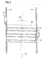
- FIG. 2 This is exemplary in the FIG. 2 showing a state in which the pallet 108 at least partially passed the stop 112.
- the pallet 108 is rotated by an angle 200 relative to the extension direction 106 and thus the conveying direction of the roller conveyor 100.
- This slight rotation which may for example be in the range between 5 ° and 7 °, it is prevented that the runners of the pallet 108 and the rollers 102 are in absolutely parallel alignment with each other. This ensures that, with regard to a single skid, even in the case of a somewhat higher roller 102 not the entire width of the runner has to accumulate on the roller 102 at the same time.
- the turning operation in the angle 200 takes place fully automatically and forcibly guided when depositing the pallet 108 on the area of the device and thus of the stop 110 and stop 112. This happens because when settling initially the bevels of the stops 110 and 112 for centering the pallet 108 on the roller conveyor 100 provide. However, as the pallet 108 slips down the slope along the chamfer, as soon as the stop 112 slides against the release mechanism 114, the release mechanism 114 is actuated. Until this time of actuation, the diagonal displacement of the stops 110 and 112 causes the automatic fully automatic rotation of the pallet. However, as soon as the release mechanism 114 is actuated, the stop 112 is moved away from the range of movement of the pallet 108, so that the pallet 108 can pass through the stopper 112 unhindered in the conveying direction.
- the release mechanism only a mobility of the stop away from the roller conveyor, that is in the FIGS. 1 and 2 to the right, is possible. If, in this case, the pallets 108 have sufficient momentum, they are also able to independently push the stopper 112 to the right when passing the stopper and thus to pass the stopper 112 completely. However, this could lead to a slight deceleration of the pallets 108.
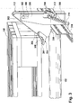
- FIG. 3 shows a detailed perspective view of the second stop 112 and the release mechanism 114. It is clearly visible that the stop 112 has the bevel 302, which points in the direction of the roller 102 and thus the roller conveyor. When placing the pallet 108 with its runners, the pallet 108 slides along the chamfer 302 in the direction of the roller conveyor.
- Release mechanism 114 and stop 112 are operatively connected via a lever link 308.
- the stop 112 is just in the fixed position in which the stop 112 is fixed via a locking seat 316 on the frame strut 314 of the roller conveyor 100.
- the lever 308 of the release mechanism will push the stop 112 upwardly.
- the stop 112 is lifted out of its catch seat 316 and can in the FIG. 3 to swing to the right.
- the release mechanism 114 includes a chamfer 306 and a support surface 304.
- the chamfer 306 forms an extension of the chamfer 302.
- the support surface 304 is located below the chamfer 306th
- the pallet 108 If the pallet 108 has slid down with its runners along the chamfer 302, it will come to rest on the chamfer 306. As a result, a movement process is initiated by the force now acting on the chamfer 306 is transmitted via the lever 308 to the stop 112.
- the stop 112 and the lever 308 are rotatably connected to one another via an axis 112.
- the axle 312 is mounted on a frame member 300, wherein the frame member 300 is in turn fixed to the strut 314.
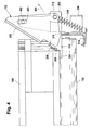
- the pallet 108 will continue to slide along the slope 306. Ultimately, it will come to lie on the support surface 304, in which case the stopper 112 is completely lifted out of its catch seat 316. Until then, due to the slope 306 and the mobility of the stop 112 this attack to the right, the means to be in direction 404, to be panned.
- the process of pivoting in the direction 404 and the lifting of the stop 112 from the locking seat 316 upwards is guided by a slotted guide, formed by the link 400 and the sliding block 402.
- the sliding block can be arranged, for example, on the stop 112, whereas the gate 400 is part of the frame element 300. This is also possible vice versa.
- the axle 312 is connected to the frame member 300 and / or the frame brace 314 via one or more springs 310. This makes it possible that after leaving the support surface 304 by the pallet and thus relieving the release mechanism 114 this again independently in the original position, ie in FIG. 3 shown position, snaps back. As a result, the stop 112 is automatically swung back to its original position.
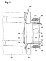
- FIG. 5 shows a view of the stop 112 ( FIG. 3 ) from above.
- the lever mechanism 308 which consists of different arms, which are arranged on the release mechanism 114. Through these arms, the axis 312 is guided, which connect the lever connection 308 and the stopper 112 rotatably with each other.
- FIG. 5 It can also be seen in FIG. 5 an elongate guide element 500, which is arranged on the release mechanism 114 in the present case.
- the guide element 500 extends counter to the conveying direction of the roller conveyor and pointing away from the first stop 110. Like in the FIG. 5 can be recognized, this guide element for free positioning and guiding the pallet 108 when passing the stopper 112.
- the guide member 500 may also be disposed on the stop 112.
Landscapes
- Engineering & Computer Science (AREA)
- Mechanical Engineering (AREA)
- Rollers For Roller Conveyors For Transfer (AREA)
Applications Claiming Priority (1)
| Application Number | Priority Date | Filing Date | Title |
|---|---|---|---|
| DE201310221392 DE102013221392A1 (de) | 2013-10-22 | 2013-10-22 | Vorrichtung zur Zwangspositionierung von einem Ladungsträger auf einer Rollenbahn |
Publications (1)
| Publication Number | Publication Date |
|---|---|
| EP2865617A1 true EP2865617A1 (fr) | 2015-04-29 |
Family
ID=51357794
Family Applications (1)
| Application Number | Title | Priority Date | Filing Date |
|---|---|---|---|
| EP20140181104 Withdrawn EP2865617A1 (fr) | 2013-10-22 | 2014-08-15 | Dispositif pour positioner une palette sur un convoyeur à rouleaux |
Country Status (2)
| Country | Link |
|---|---|
| EP (1) | EP2865617A1 (fr) |
| DE (1) | DE102013221392A1 (fr) |
Cited By (3)
| Publication number | Priority date | Publication date | Assignee | Title |
|---|---|---|---|---|
| CN111001795A (zh) * | 2019-12-31 | 2020-04-14 | 巢湖学院 | 一种防止砂箱逆行的装置和方法 |
| EP3825256A1 (fr) | 2019-11-22 | 2021-05-26 | Moffett Automated Storage Limited | Appareil d'alignement de palette |
| CN120117310A (zh) * | 2025-03-31 | 2025-06-10 | 吉林农业科技学院 | 一种基于农贸商品仓储中心智慧物流商品存放货架 |
Families Citing this family (1)
| Publication number | Priority date | Publication date | Assignee | Title |
|---|---|---|---|---|
| DE102021006362B4 (de) * | 2021-12-28 | 2024-04-04 | Gebhardt Fördertechnik GmbH | Zentrierstation und Verfahren zum Handhaben zumindest eines Ladungsträgers |
Citations (5)
| Publication number | Priority date | Publication date | Assignee | Title |
|---|---|---|---|---|
| DE2848820A1 (de) | 1978-11-10 | 1980-05-14 | Enzinger Union Werke Ag | Vorrichtung zum drehen von rechteckigen stueckguetern, z.b. flaschenkaesten |
| DE3311116A1 (de) * | 1983-03-26 | 1984-09-27 | SMS Schloemann-Siemag AG, 4000 Düsseldorf | Verfahren und vorrichtung zum ausrichten von blechen auf einem rollgang |
| DE10043991A1 (de) | 2000-09-05 | 2002-04-04 | Jagenberg Diana Gmbh | Vorrichtung zum Drehen flacher Gegenstände, insbesondere von Faltschachtelzuschnitten |
| DE20313194U1 (de) * | 2003-08-26 | 2003-11-13 | Bito-Lagertechnik Bittmann GmbH, 55590 Meisenheim | Durchlaufregal mit Separiervorrichtung |
| DE102010012407A1 (de) | 2010-03-23 | 2011-09-29 | Weber Maschinenbau Gmbh Breidenbach | Vorrichtung zum Fördern von Produkten |
-
2013
- 2013-10-22 DE DE201310221392 patent/DE102013221392A1/de not_active Withdrawn
-
2014
- 2014-08-15 EP EP20140181104 patent/EP2865617A1/fr not_active Withdrawn
Patent Citations (5)
| Publication number | Priority date | Publication date | Assignee | Title |
|---|---|---|---|---|
| DE2848820A1 (de) | 1978-11-10 | 1980-05-14 | Enzinger Union Werke Ag | Vorrichtung zum drehen von rechteckigen stueckguetern, z.b. flaschenkaesten |
| DE3311116A1 (de) * | 1983-03-26 | 1984-09-27 | SMS Schloemann-Siemag AG, 4000 Düsseldorf | Verfahren und vorrichtung zum ausrichten von blechen auf einem rollgang |
| DE10043991A1 (de) | 2000-09-05 | 2002-04-04 | Jagenberg Diana Gmbh | Vorrichtung zum Drehen flacher Gegenstände, insbesondere von Faltschachtelzuschnitten |
| DE20313194U1 (de) * | 2003-08-26 | 2003-11-13 | Bito-Lagertechnik Bittmann GmbH, 55590 Meisenheim | Durchlaufregal mit Separiervorrichtung |
| DE102010012407A1 (de) | 2010-03-23 | 2011-09-29 | Weber Maschinenbau Gmbh Breidenbach | Vorrichtung zum Fördern von Produkten |
Cited By (4)
| Publication number | Priority date | Publication date | Assignee | Title |
|---|---|---|---|---|
| EP3825256A1 (fr) | 2019-11-22 | 2021-05-26 | Moffett Automated Storage Limited | Appareil d'alignement de palette |
| GB2590070A (en) * | 2019-11-22 | 2021-06-23 | Moffett Automated Storage Ltd | Pallet alignment apparatus |
| CN111001795A (zh) * | 2019-12-31 | 2020-04-14 | 巢湖学院 | 一种防止砂箱逆行的装置和方法 |
| CN120117310A (zh) * | 2025-03-31 | 2025-06-10 | 吉林农业科技学院 | 一种基于农贸商品仓储中心智慧物流商品存放货架 |
Also Published As
| Publication number | Publication date |
|---|---|
| DE102013221392A1 (de) | 2015-04-23 |
Similar Documents
| Publication | Publication Date | Title |
|---|---|---|
| EP2691325B1 (fr) | Module de transport à rouleaux comportant un dispositif de séparation | |
| EP3878775B1 (fr) | Bande à rouleaux pourvu de dispositif de freinage | |
| DE102021209986A1 (de) | Handhabungssystem zur automatischen Übergabe und Vereinzelung von Ladungsträgern | |
| EP2390185B1 (fr) | Transporteur de conteneur | |
| DE102018120404B4 (de) | Betätigungseinrichtung zur Betätigung einer Trennvorrichtung für eine Schwerkraftförderbahn | |
| EP2695823A2 (fr) | Palette pour chariots roulants | |
| DE102013221392A1 (de) | Vorrichtung zur Zwangspositionierung von einem Ladungsträger auf einer Rollenbahn | |
| DE102012001503B4 (de) | Palette zum Transportieren von Rollwagen | |
| EP1999057A2 (fr) | Dispositif de transport d'un ou plusieurs rouleaux de matériau comportant un système de transport et un système de logistique de rouleaux | |
| DE10020909B4 (de) | Vorrichtung zur Förderung einer Vorratsrolle | |
| DE1806888A1 (de) | Foerdervorrichtung zum Ausrichten von Gegenstaenden | |
| WO2013006880A1 (fr) | Moyen de réception de charge destiné à déposer et enlever des marchandises | |
| CH618939A5 (fr) | ||
| DE202010009390U1 (de) | Palette | |
| DE202011106718U1 (de) | Palette mit Verriegelung | |
| DE2726770C2 (de) | Vorrichtung zum staudrucklosen Fördern von Ladungsgutträgern | |
| EP2994402B1 (fr) | Manipulateur | |
| DE19958330A1 (de) | Rollenbahn | |
| EP2664540B1 (fr) | Dispositif de verrouillage pour sécuriser et guider au moins un colis | |
| DE19519615C2 (de) | Vorrichtung für das Stapeln von Profilen | |
| DE102015001542A1 (de) | Verfahren und Vorrichtung zur Handhabung von Ladungsträgern | |
| EP0905061B1 (fr) | Dispositif de commande monté diagonalement pour des arrêts de containers sur des transporteurs à rouleaux | |
| DE102010046197A1 (de) | Vorrichtung zum Fördern von Paletten | |
| DE102015001543A1 (de) | Vorrichtung zur Handhabung von Ladungsträgern und Verfahren zum Betrieb einer solchen Vorrichtung | |
| EP1614804A1 (fr) | Installation de transport avec deux rails superposés et comportant un aiguillage |
Legal Events
| Date | Code | Title | Description |
|---|---|---|---|
| PUAI | Public reference made under article 153(3) epc to a published international application that has entered the european phase |
Free format text: ORIGINAL CODE: 0009012 |
|
| 17P | Request for examination filed |
Effective date: 20140815 |
|
| AK | Designated contracting states |
Kind code of ref document: A1 Designated state(s): AL AT BE BG CH CY CZ DE DK EE ES FI FR GB GR HR HU IE IS IT LI LT LU LV MC MK MT NL NO PL PT RO RS SE SI SK SM TR |
|
| AX | Request for extension of the european patent |
Extension state: BA ME |
|
| R17P | Request for examination filed (corrected) |
Effective date: 20151029 |
|
| RBV | Designated contracting states (corrected) |
Designated state(s): AL AT BE BG CH CY CZ DE DK EE ES FI FR GB GR HR HU IE IS IT LI LT LU LV MC MK MT NL NO PL PT RO RS SE SI SK SM TR |
|
| STAA | Information on the status of an ep patent application or granted ep patent |
Free format text: STATUS: THE APPLICATION HAS BEEN WITHDRAWN |
|
| 18W | Application withdrawn |
Effective date: 20151118 |