EP2865729B1 - Wärmeableitende folie sowie deren herstellungsverfahren - Google Patents
Wärmeableitende folie sowie deren herstellungsverfahren Download PDFInfo
- Publication number
- EP2865729B1 EP2865729B1 EP14188322.3A EP14188322A EP2865729B1 EP 2865729 B1 EP2865729 B1 EP 2865729B1 EP 14188322 A EP14188322 A EP 14188322A EP 2865729 B1 EP2865729 B1 EP 2865729B1
- Authority
- EP
- European Patent Office
- Prior art keywords
- heat
- carbon nanotube
- graphene particles
- layer
- fine graphene
- Prior art date
- Legal status (The legal status is an assumption and is not a legal conclusion. Google has not performed a legal analysis and makes no representation as to the accuracy of the status listed.)
- Not-in-force
Links
- 238000004519 manufacturing process Methods 0.000 title claims description 13
- OKTJSMMVPCPJKN-UHFFFAOYSA-N Carbon Chemical compound [C] OKTJSMMVPCPJKN-UHFFFAOYSA-N 0.000 claims description 273
- 229910021389 graphene Inorganic materials 0.000 claims description 126
- 239000002245 particle Substances 0.000 claims description 120
- 239000002041 carbon nanotube Substances 0.000 claims description 116
- 229910021393 carbon nanotube Inorganic materials 0.000 claims description 116
- 239000002985 plastic film Substances 0.000 claims description 90
- 229920006255 plastic film Polymers 0.000 claims description 90
- 239000000203 mixture Substances 0.000 claims description 89
- 238000003825 pressing Methods 0.000 claims description 65
- 239000006185 dispersion Substances 0.000 claims description 61
- 239000011347 resin Substances 0.000 claims description 60
- 229920005989 resin Polymers 0.000 claims description 60
- 239000011230 binding agent Substances 0.000 claims description 51
- 239000003960 organic solvent Substances 0.000 claims description 17
- 238000001035 drying Methods 0.000 claims description 16
- 238000010438 heat treatment Methods 0.000 claims description 15
- 239000010410 layer Substances 0.000 description 244
- 239000010408 film Substances 0.000 description 63
- 229910002804 graphite Inorganic materials 0.000 description 18
- 239000010439 graphite Substances 0.000 description 18
- 238000010030 laminating Methods 0.000 description 18
- 238000000034 method Methods 0.000 description 17
- KFZMGEQAYNKOFK-UHFFFAOYSA-N Isopropanol Chemical compound CC(C)O KFZMGEQAYNKOFK-UHFFFAOYSA-N 0.000 description 14
- -1 polypropylene Polymers 0.000 description 10
- ZWEHNKRNPOVVGH-UHFFFAOYSA-N 2-Butanone Chemical compound CCC(C)=O ZWEHNKRNPOVVGH-UHFFFAOYSA-N 0.000 description 9
- 229920003229 poly(methyl methacrylate) Polymers 0.000 description 9
- 239000004926 polymethyl methacrylate Substances 0.000 description 9
- 238000005452 bending Methods 0.000 description 7
- 230000000052 comparative effect Effects 0.000 description 7
- 230000000149 penetrating effect Effects 0.000 description 7
- 229920002799 BoPET Polymers 0.000 description 6
- 238000005520 cutting process Methods 0.000 description 6
- 239000011261 inert gas Substances 0.000 description 6
- 230000035699 permeability Effects 0.000 description 6
- 239000011148 porous material Substances 0.000 description 6
- CTQNGGLPUBDAKN-UHFFFAOYSA-N O-Xylene Chemical compound CC1=CC=CC=C1C CTQNGGLPUBDAKN-UHFFFAOYSA-N 0.000 description 5
- 229920000139 polyethylene terephthalate Polymers 0.000 description 5
- 239000005020 polyethylene terephthalate Substances 0.000 description 5
- 238000007789 sealing Methods 0.000 description 5
- 238000005507 spraying Methods 0.000 description 5
- 239000008096 xylene Substances 0.000 description 5
- 239000004743 Polypropylene Substances 0.000 description 4
- 238000005054 agglomeration Methods 0.000 description 4
- 230000002776 aggregation Effects 0.000 description 4
- XAGFODPZIPBFFR-UHFFFAOYSA-N aluminium Chemical compound [Al] XAGFODPZIPBFFR-UHFFFAOYSA-N 0.000 description 4
- 229910052782 aluminium Inorganic materials 0.000 description 4
- 230000017525 heat dissipation Effects 0.000 description 4
- 229920001721 polyimide Polymers 0.000 description 4
- 229920001155 polypropylene Polymers 0.000 description 4
- 239000000758 substrate Substances 0.000 description 4
- UHOVQNZJYSORNB-UHFFFAOYSA-N Benzene Chemical group C1=CC=CC=C1 UHOVQNZJYSORNB-UHFFFAOYSA-N 0.000 description 3
- 229910052799 carbon Inorganic materials 0.000 description 3
- 238000003763 carbonization Methods 0.000 description 3
- 239000011248 coating agent Substances 0.000 description 3
- 238000000576 coating method Methods 0.000 description 3
- 239000002131 composite material Substances 0.000 description 3
- 238000007599 discharging Methods 0.000 description 3
- 230000000694 effects Effects 0.000 description 3
- 230000006870 function Effects 0.000 description 3
- 238000002156 mixing Methods 0.000 description 3
- VLKZOEOYAKHREP-UHFFFAOYSA-N n-Hexane Chemical compound CCCCCC VLKZOEOYAKHREP-UHFFFAOYSA-N 0.000 description 3
- 239000002904 solvent Substances 0.000 description 3
- 238000010998 test method Methods 0.000 description 3
- 239000004925 Acrylic resin Substances 0.000 description 2
- 229920000178 Acrylic resin Polymers 0.000 description 2
- 239000004642 Polyimide Substances 0.000 description 2
- 239000004793 Polystyrene Substances 0.000 description 2
- QAOWNCQODCNURD-UHFFFAOYSA-N Sulfuric acid Chemical compound OS(O)(=O)=O QAOWNCQODCNURD-UHFFFAOYSA-N 0.000 description 2
- 239000002253 acid Substances 0.000 description 2
- 150000001298 alcohols Chemical class 0.000 description 2
- 150000004945 aromatic hydrocarbons Chemical class 0.000 description 2
- 125000004432 carbon atom Chemical group C* 0.000 description 2
- 150000001875 compounds Chemical class 0.000 description 2
- 238000000280 densification Methods 0.000 description 2
- 229910003460 diamond Inorganic materials 0.000 description 2
- 239000010432 diamond Substances 0.000 description 2
- 238000009826 distribution Methods 0.000 description 2
- 239000003574 free electron Substances 0.000 description 2
- 239000011229 interlayer Substances 0.000 description 2
- 230000001788 irregular Effects 0.000 description 2
- 150000002576 ketones Chemical class 0.000 description 2
- 238000003475 lamination Methods 0.000 description 2
- 239000000463 material Substances 0.000 description 2
- 239000012046 mixed solvent Substances 0.000 description 2
- 238000012856 packing Methods 0.000 description 2
- 125000001997 phenyl group Chemical group [H]C1=C([H])C([H])=C(*)C([H])=C1[H] 0.000 description 2
- 229920002223 polystyrene Polymers 0.000 description 2
- 238000011160 research Methods 0.000 description 2
- 239000011369 resultant mixture Substances 0.000 description 2
- 239000000565 sealant Substances 0.000 description 2
- 238000012360 testing method Methods 0.000 description 2
- 238000011144 upstream manufacturing Methods 0.000 description 2
- RYGMFSIKBFXOCR-UHFFFAOYSA-N Copper Chemical compound [Cu] RYGMFSIKBFXOCR-UHFFFAOYSA-N 0.000 description 1
- PXHVJJICTQNCMI-UHFFFAOYSA-N Nickel Chemical compound [Ni] PXHVJJICTQNCMI-UHFFFAOYSA-N 0.000 description 1
- 239000004696 Poly ether ether ketone Substances 0.000 description 1
- 229920002319 Poly(methyl acrylate) Polymers 0.000 description 1
- 239000004952 Polyamide Substances 0.000 description 1
- 239000004695 Polyether sulfone Substances 0.000 description 1
- 239000004734 Polyphenylene sulfide Substances 0.000 description 1
- 239000004372 Polyvinyl alcohol Substances 0.000 description 1
- UCKMPCXJQFINFW-UHFFFAOYSA-N Sulphide Chemical compound [S-2] UCKMPCXJQFINFW-UHFFFAOYSA-N 0.000 description 1
- 229920000122 acrylonitrile butadiene styrene Polymers 0.000 description 1
- 239000000654 additive Substances 0.000 description 1
- 230000000996 additive effect Effects 0.000 description 1
- 239000000853 adhesive Substances 0.000 description 1
- 230000001070 adhesive effect Effects 0.000 description 1
- 239000012790 adhesive layer Substances 0.000 description 1
- 239000004840 adhesive resin Substances 0.000 description 1
- 229920006223 adhesive resin Polymers 0.000 description 1
- 150000001338 aliphatic hydrocarbons Chemical class 0.000 description 1
- QVGXLLKOCUKJST-UHFFFAOYSA-N atomic oxygen Chemical compound [O] QVGXLLKOCUKJST-UHFFFAOYSA-N 0.000 description 1
- 238000009835 boiling Methods 0.000 description 1
- 150000001721 carbon Chemical group 0.000 description 1
- 230000008859 change Effects 0.000 description 1
- 239000011247 coating layer Substances 0.000 description 1
- 230000006835 compression Effects 0.000 description 1
- 238000007906 compression Methods 0.000 description 1
- 229910052802 copper Inorganic materials 0.000 description 1
- 239000010949 copper Substances 0.000 description 1
- 238000005336 cracking Methods 0.000 description 1
- 239000013078 crystal Substances 0.000 description 1
- 230000001747 exhibiting effect Effects 0.000 description 1
- 239000006260 foam Substances 0.000 description 1
- 238000003384 imaging method Methods 0.000 description 1
- 238000009413 insulation Methods 0.000 description 1
- 125000001449 isopropyl group Chemical group [H]C([H])([H])C([H])(*)C([H])([H])[H] 0.000 description 1
- 230000007257 malfunction Effects 0.000 description 1
- 238000005259 measurement Methods 0.000 description 1
- 230000015654 memory Effects 0.000 description 1
- 238000012986 modification Methods 0.000 description 1
- 230000004048 modification Effects 0.000 description 1
- 239000002048 multi walled nanotube Substances 0.000 description 1
- 229910052760 oxygen Inorganic materials 0.000 description 1
- 239000001301 oxygen Substances 0.000 description 1
- 230000002093 peripheral effect Effects 0.000 description 1
- 229920003023 plastic Polymers 0.000 description 1
- 239000004033 plastic Substances 0.000 description 1
- 229920000058 polyacrylate Polymers 0.000 description 1
- 229920002647 polyamide Polymers 0.000 description 1
- 229920000412 polyarylene Polymers 0.000 description 1
- 239000004417 polycarbonate Substances 0.000 description 1
- 229920000515 polycarbonate Polymers 0.000 description 1
- 229920000728 polyester Polymers 0.000 description 1
- 229920006393 polyether sulfone Polymers 0.000 description 1
- 229920002530 polyetherether ketone Polymers 0.000 description 1
- 229920000098 polyolefin Polymers 0.000 description 1
- 229920000069 polyphenylene sulfide Polymers 0.000 description 1
- 229920005990 polystyrene resin Polymers 0.000 description 1
- 229920002451 polyvinyl alcohol Polymers 0.000 description 1
- 239000004800 polyvinyl chloride Substances 0.000 description 1
- 229920000915 polyvinyl chloride Polymers 0.000 description 1
- 239000002243 precursor Substances 0.000 description 1
- 238000002360 preparation method Methods 0.000 description 1
- 230000002250 progressing effect Effects 0.000 description 1
- 238000005096 rolling process Methods 0.000 description 1
- 229920006395 saturated elastomer Polymers 0.000 description 1
- 239000002356 single layer Substances 0.000 description 1
- 239000002109 single walled nanotube Substances 0.000 description 1
- 239000000126 substance Substances 0.000 description 1
- 239000010409 thin film Substances 0.000 description 1
- 238000009827 uniform distribution Methods 0.000 description 1
- 238000009834 vaporization Methods 0.000 description 1
- 230000008016 vaporization Effects 0.000 description 1
- 229920002554 vinyl polymer Polymers 0.000 description 1
- 238000005406 washing Methods 0.000 description 1
- 238000004804 winding Methods 0.000 description 1
Images


Classifications
-
- C—CHEMISTRY; METALLURGY
- C09—DYES; PAINTS; POLISHES; NATURAL RESINS; ADHESIVES; COMPOSITIONS NOT OTHERWISE PROVIDED FOR; APPLICATIONS OF MATERIALS NOT OTHERWISE PROVIDED FOR
- C09K—MATERIALS FOR MISCELLANEOUS APPLICATIONS, NOT PROVIDED FOR ELSEWHERE
- C09K5/00—Heat-transfer, heat-exchange or heat-storage materials, e.g. refrigerants; Materials for the production of heat or cold by chemical reactions other than by combustion
- C09K5/08—Materials not undergoing a change of physical state when used
- C09K5/14—Solid materials, e.g. powdery or granular
-
- B—PERFORMING OPERATIONS; TRANSPORTING
- B29—WORKING OF PLASTICS; WORKING OF SUBSTANCES IN A PLASTIC STATE IN GENERAL
- B29C—SHAPING OR JOINING OF PLASTICS; SHAPING OF MATERIAL IN A PLASTIC STATE, NOT OTHERWISE PROVIDED FOR; AFTER-TREATMENT OF THE SHAPED PRODUCTS, e.g. REPAIRING
- B29C65/00—Joining or sealing of preformed parts, e.g. welding of plastics materials; Apparatus therefor
-
- B—PERFORMING OPERATIONS; TRANSPORTING
- B29—WORKING OF PLASTICS; WORKING OF SUBSTANCES IN A PLASTIC STATE IN GENERAL
- B29C—SHAPING OR JOINING OF PLASTICS; SHAPING OF MATERIAL IN A PLASTIC STATE, NOT OTHERWISE PROVIDED FOR; AFTER-TREATMENT OF THE SHAPED PRODUCTS, e.g. REPAIRING
- B29C66/00—General aspects of processes or apparatus for joining preformed parts
-
- B—PERFORMING OPERATIONS; TRANSPORTING
- B29—WORKING OF PLASTICS; WORKING OF SUBSTANCES IN A PLASTIC STATE IN GENERAL
- B29C—SHAPING OR JOINING OF PLASTICS; SHAPING OF MATERIAL IN A PLASTIC STATE, NOT OTHERWISE PROVIDED FOR; AFTER-TREATMENT OF THE SHAPED PRODUCTS, e.g. REPAIRING
- B29C70/00—Shaping composites, i.e. plastics material comprising reinforcements, fillers or preformed parts, e.g. inserts
- B29C70/003—Shaping composites, i.e. plastics material comprising reinforcements, fillers or preformed parts, e.g. inserts characterised by the matrix material, e.g. material composition or physical properties
- B29C70/0035—Shaping composites, i.e. plastics material comprising reinforcements, fillers or preformed parts, e.g. inserts characterised by the matrix material, e.g. material composition or physical properties comprising two or more matrix materials
-
- B—PERFORMING OPERATIONS; TRANSPORTING
- B32—LAYERED PRODUCTS
- B32B—LAYERED PRODUCTS, i.e. PRODUCTS BUILT-UP OF STRATA OF FLAT OR NON-FLAT, e.g. CELLULAR OR HONEYCOMB, FORM
- B32B27/00—Layered products comprising a layer of synthetic resin
- B32B27/06—Layered products comprising a layer of synthetic resin as the main or only constituent of a layer, which is next to another layer of the same or of a different material
- B32B27/08—Layered products comprising a layer of synthetic resin as the main or only constituent of a layer, which is next to another layer of the same or of a different material of synthetic resin
-
- B—PERFORMING OPERATIONS; TRANSPORTING
- B32—LAYERED PRODUCTS
- B32B—LAYERED PRODUCTS, i.e. PRODUCTS BUILT-UP OF STRATA OF FLAT OR NON-FLAT, e.g. CELLULAR OR HONEYCOMB, FORM
- B32B27/00—Layered products comprising a layer of synthetic resin
- B32B27/18—Layered products comprising a layer of synthetic resin characterised by the use of special additives
- B32B27/20—Layered products comprising a layer of synthetic resin characterised by the use of special additives using fillers, pigments, thixotroping agents
-
- B—PERFORMING OPERATIONS; TRANSPORTING
- B32—LAYERED PRODUCTS
- B32B—LAYERED PRODUCTS, i.e. PRODUCTS BUILT-UP OF STRATA OF FLAT OR NON-FLAT, e.g. CELLULAR OR HONEYCOMB, FORM
- B32B27/00—Layered products comprising a layer of synthetic resin
- B32B27/30—Layered products comprising a layer of synthetic resin comprising vinyl (co)polymers; comprising acrylic (co)polymers
- B32B27/308—Layered products comprising a layer of synthetic resin comprising vinyl (co)polymers; comprising acrylic (co)polymers comprising acrylic (co)polymers
-
- B—PERFORMING OPERATIONS; TRANSPORTING
- B32—LAYERED PRODUCTS
- B32B—LAYERED PRODUCTS, i.e. PRODUCTS BUILT-UP OF STRATA OF FLAT OR NON-FLAT, e.g. CELLULAR OR HONEYCOMB, FORM
- B32B27/00—Layered products comprising a layer of synthetic resin
- B32B27/36—Layered products comprising a layer of synthetic resin comprising polyesters
-
- B—PERFORMING OPERATIONS; TRANSPORTING
- B32—LAYERED PRODUCTS
- B32B—LAYERED PRODUCTS, i.e. PRODUCTS BUILT-UP OF STRATA OF FLAT OR NON-FLAT, e.g. CELLULAR OR HONEYCOMB, FORM
- B32B37/00—Methods or apparatus for laminating, e.g. by curing or by ultrasonic bonding
-
- B—PERFORMING OPERATIONS; TRANSPORTING
- B32—LAYERED PRODUCTS
- B32B—LAYERED PRODUCTS, i.e. PRODUCTS BUILT-UP OF STRATA OF FLAT OR NON-FLAT, e.g. CELLULAR OR HONEYCOMB, FORM
- B32B37/00—Methods or apparatus for laminating, e.g. by curing or by ultrasonic bonding
- B32B37/14—Methods or apparatus for laminating, e.g. by curing or by ultrasonic bonding characterised by the properties of the layers
- B32B37/24—Methods or apparatus for laminating, e.g. by curing or by ultrasonic bonding characterised by the properties of the layers with at least one layer not being coherent before laminating, e.g. made up from granular material sprinkled onto a substrate
-
- F—MECHANICAL ENGINEERING; LIGHTING; HEATING; WEAPONS; BLASTING
- F28—HEAT EXCHANGE IN GENERAL
- F28F—DETAILS OF HEAT-EXCHANGE AND HEAT-TRANSFER APPARATUS, OF GENERAL APPLICATION
- F28F21/00—Constructions of heat-exchange apparatus characterised by the selection of particular materials
- F28F21/02—Constructions of heat-exchange apparatus characterised by the selection of particular materials of carbon, e.g. graphite
-
- F—MECHANICAL ENGINEERING; LIGHTING; HEATING; WEAPONS; BLASTING
- F28—HEAT EXCHANGE IN GENERAL
- F28F—DETAILS OF HEAT-EXCHANGE AND HEAT-TRANSFER APPARATUS, OF GENERAL APPLICATION
- F28F21/00—Constructions of heat-exchange apparatus characterised by the selection of particular materials
- F28F21/06—Constructions of heat-exchange apparatus characterised by the selection of particular materials of plastics material
-
- H—ELECTRICITY
- H05—ELECTRIC TECHNIQUES NOT OTHERWISE PROVIDED FOR
- H05K—PRINTED CIRCUITS; CASINGS OR CONSTRUCTIONAL DETAILS OF ELECTRIC APPARATUS; MANUFACTURE OF ASSEMBLAGES OF ELECTRICAL COMPONENTS
- H05K7/00—Constructional details common to different types of electric apparatus
- H05K7/20—Modifications to facilitate cooling, ventilating, or heating
- H05K7/2039—Modifications to facilitate cooling, ventilating, or heating characterised by the heat transfer by conduction from the heat generating element to a dissipating body
- H05K7/20436—Inner thermal coupling elements in heat dissipating housings, e.g. protrusions or depressions integrally formed in the housing
- H05K7/20445—Inner thermal coupling elements in heat dissipating housings, e.g. protrusions or depressions integrally formed in the housing the coupling element being an additional piece, e.g. thermal standoff
- H05K7/20472—Sheet interfaces
- H05K7/20481—Sheet interfaces characterised by the material composition exhibiting specific thermal properties
-
- B—PERFORMING OPERATIONS; TRANSPORTING
- B32—LAYERED PRODUCTS
- B32B—LAYERED PRODUCTS, i.e. PRODUCTS BUILT-UP OF STRATA OF FLAT OR NON-FLAT, e.g. CELLULAR OR HONEYCOMB, FORM
- B32B2250/00—Layers arrangement
- B32B2250/03—3 layers
-
- B—PERFORMING OPERATIONS; TRANSPORTING
- B32—LAYERED PRODUCTS
- B32B—LAYERED PRODUCTS, i.e. PRODUCTS BUILT-UP OF STRATA OF FLAT OR NON-FLAT, e.g. CELLULAR OR HONEYCOMB, FORM
- B32B2264/00—Composition or properties of particles which form a particulate layer or are present as additives
- B32B2264/10—Inorganic particles
- B32B2264/107—Ceramic
- B32B2264/108—Carbon, e.g. graphite particles
-
- B—PERFORMING OPERATIONS; TRANSPORTING
- B32—LAYERED PRODUCTS
- B32B—LAYERED PRODUCTS, i.e. PRODUCTS BUILT-UP OF STRATA OF FLAT OR NON-FLAT, e.g. CELLULAR OR HONEYCOMB, FORM
- B32B2307/00—Properties of the layers or laminate
- B32B2307/30—Properties of the layers or laminate having particular thermal properties
- B32B2307/302—Conductive
-
- B—PERFORMING OPERATIONS; TRANSPORTING
- B32—LAYERED PRODUCTS
- B32B—LAYERED PRODUCTS, i.e. PRODUCTS BUILT-UP OF STRATA OF FLAT OR NON-FLAT, e.g. CELLULAR OR HONEYCOMB, FORM
- B32B2313/00—Elements other than metals
- B32B2313/04—Carbon
-
- B—PERFORMING OPERATIONS; TRANSPORTING
- B32—LAYERED PRODUCTS
- B32B—LAYERED PRODUCTS, i.e. PRODUCTS BUILT-UP OF STRATA OF FLAT OR NON-FLAT, e.g. CELLULAR OR HONEYCOMB, FORM
- B32B2333/00—Polymers of unsaturated acids or derivatives thereof
- B32B2333/04—Polymers of esters
- B32B2333/12—Polymers of methacrylic acid esters, e.g. PMMA, i.e. polymethylmethacrylate
-
- B—PERFORMING OPERATIONS; TRANSPORTING
- B32—LAYERED PRODUCTS
- B32B—LAYERED PRODUCTS, i.e. PRODUCTS BUILT-UP OF STRATA OF FLAT OR NON-FLAT, e.g. CELLULAR OR HONEYCOMB, FORM
- B32B2367/00—Polyesters, e.g. PET, i.e. polyethylene terephthalate
-
- B—PERFORMING OPERATIONS; TRANSPORTING
- B32—LAYERED PRODUCTS
- B32B—LAYERED PRODUCTS, i.e. PRODUCTS BUILT-UP OF STRATA OF FLAT OR NON-FLAT, e.g. CELLULAR OR HONEYCOMB, FORM
- B32B2457/00—Electrical equipment
-
- Y—GENERAL TAGGING OF NEW TECHNOLOGICAL DEVELOPMENTS; GENERAL TAGGING OF CROSS-SECTIONAL TECHNOLOGIES SPANNING OVER SEVERAL SECTIONS OF THE IPC; TECHNICAL SUBJECTS COVERED BY FORMER USPC CROSS-REFERENCE ART COLLECTIONS [XRACs] AND DIGESTS
- Y10—TECHNICAL SUBJECTS COVERED BY FORMER USPC
- Y10T—TECHNICAL SUBJECTS COVERED BY FORMER US CLASSIFICATION
- Y10T428/00—Stock material or miscellaneous articles
- Y10T428/249921—Web or sheet containing structurally defined element or component
-
- Y—GENERAL TAGGING OF NEW TECHNOLOGICAL DEVELOPMENTS; GENERAL TAGGING OF CROSS-SECTIONAL TECHNOLOGIES SPANNING OVER SEVERAL SECTIONS OF THE IPC; TECHNICAL SUBJECTS COVERED BY FORMER USPC CROSS-REFERENCE ART COLLECTIONS [XRACs] AND DIGESTS
- Y10—TECHNICAL SUBJECTS COVERED BY FORMER USPC
- Y10T—TECHNICAL SUBJECTS COVERED BY FORMER US CLASSIFICATION
- Y10T428/00—Stock material or miscellaneous articles
- Y10T428/25—Web or sheet containing structurally defined element or component and including a second component containing structurally defined particles
-
- Y—GENERAL TAGGING OF NEW TECHNOLOGICAL DEVELOPMENTS; GENERAL TAGGING OF CROSS-SECTIONAL TECHNOLOGIES SPANNING OVER SEVERAL SECTIONS OF THE IPC; TECHNICAL SUBJECTS COVERED BY FORMER USPC CROSS-REFERENCE ART COLLECTIONS [XRACs] AND DIGESTS
- Y10—TECHNICAL SUBJECTS COVERED BY FORMER USPC
- Y10T—TECHNICAL SUBJECTS COVERED BY FORMER US CLASSIFICATION
- Y10T428/00—Stock material or miscellaneous articles
- Y10T428/27—Web or sheet containing structurally defined element or component, the element or component having a specified weight per unit area [e.g., gms/sq cm, lbs/sq ft, etc.]
Definitions
- the present invention relates to a heat-dissipating film for efficiently dissipating heat generated from electronic parts, etc. in small electronic appliances such as note-type personal computers, smartphones, tablets, mobile phones, etc., and its production method.
- EP 3 034 292 A1 which is a document pursuant to Article 54(3) EPC, shows an apparatus for producing a heat-dissipating film, comprising (a) means for conveying a pair of first plastic films; (b) at least one dispersion-applying means disposed for each first plastic film for applying a dispersion comprising flaky carbon and a binder resin to the first plastic film plural times; (c) a means for drying the dispersion after each application; (d) a means for laminating a pair of the first plastic films each having the resultant mixture layer of the flaky carbon and the binder resin, with the mixture layer inside; (e) a means for heat-pressing the resultant laminated film; (f) a means for peeling the first plastic films from the laminated film; (g) a means for burning the mixture layer to carbonize or burn off the binder resin in the exposed mixture layer; (h) a pressing die means for densifying the resultant burnt layer to form a heat-conductive layer; and
- the heat-dissipating film of the present invention comprises a heat-conductive layer comprising fine graphene particles and carbon nanotube uniformly dispersed, a mass ratio of the carbon nanotube to the total of the fine graphene particles and the carbon nanotube being 0.05-0.2; the fine graphene particles being substantially aligned with the heat-conductive layer; and the heat-conductive layer having a density of 1.9 g/cm 3 or more and thermal conductivity of 600 W/mK or more.
- the heat-conductive layer preferably has a thickness of 50-250 g/m 2 (expressed by the total weight of fine graphene particles and carbon nanotube per 1 m 2 ).
- the amount of the dispersion applied by one operation is preferably 5-30 g/m 2 (expressed by the total weight of fine graphene particles and carbon nanotube per 1 m 2 ).
- the organic solvent is preferably at least one selected from the group consisting of ketones, aromatic hydrocarbons and alcohols.
- the drying step is conducted preferably at 30-100°C.
- the burning of the mixture layer is preferably conducted by applying flame to the mixture layer, or exposing the mixture layer to high temperatures of 500°C or higher in the air, in vacuum or in an inert gas.
- an upper die part having a projection is pressed to the lower die part, such that the projection enters the cavity, and the combined upper and lower die parts are caused to pass through a pair of pressing rolls plural times, to densify the burnt layer.
- the die containing the burnt layer is preferably pressed with vibration.
- the second plastic film is preferably thinner than the first plastic film.
- the heat-conductive layer is preferably heat-sealed by the second plastic films.
- the heat-sealing second plastic film preferably has a sealant layer on a surface attached to the heat-conductive layer.
- the heat-conductive layer is preferably cut to a desired shape, and then sealed by the second plastic films.
- the apparatus for producing the above heat-dissipating film comprises
- Said apparatus preferably comprises pluralities of dispersion-applying means arranged with predetermined intervals along the progressing direction of each first plastic film.
- a pair of dispersion-applying means and the laminating rolls are preferably disposed in a chamber, which comprises first openings for supplying each first plastic film, a pair of hot-air-supplying openings each disposed near each first opening, an air-discharging opening, and a second opening for withdrawing the laminated film.
- a chamber which comprises first openings for supplying each first plastic film, a pair of hot-air-supplying openings each disposed near each first opening, an air-discharging opening, and a second opening for withdrawing the laminated film.
- the means for burning the mixture layer is preferably a burner for ejecting flame onto the mixture layer, or a furnace for exposing high temperatures of 500°C or higher to the mixture layer in the air, in vacuum, or in an inert gas.
- the pressing means preferably comprises a means for applying vibration to one of the pressing rolls, thereby further densifying the burnt layer by vibration pressing.
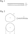
- a heat-dissipating film 1 according to an embodiment of the present invention comprises a heat-conductive layer 10, and a pair of plastic films 2, 2 adhered to both surfaces of the heat-conductive layer 10 for sealing.
- a fine graphene particle has a flake- or plate-like, multi-layer structure, in which benzene rings are two-dimensionally connected. Because the fine graphene particle has a lattice structure of benzene rings, each carbon atom is bonded to three carbon atoms, one of four peripheral electrons used for chemical bonding is in a free state (free electron). Because free electrons can move along the crystal lattice, fine graphene particles have high thermal conductivity.
- each fine graphene particle 31 has a planar contour of an irregular shape as shown in Fig. 2
- the size (diameter) of each fine graphene particle 31 is defined as a diameter d of a circle having the same area S. Because the size of each fine graphene particle 31 is expressed by a diameter d and a thickness t, the average diameter of fine graphene particles 31 used is expressed by ( ⁇ d)/n, wherein n represents the number of fine graphene particles 31 measured, and the average thickness of fine graphene particles 31 is expressed by ( ⁇ t)/n.
- the diameters d and thickness t of fine graphene particles 31 can be determined by the image treatment of photomicrographs of fine graphene particles 31.
- the average diameter of flake-like, fine graphene particles may be in a range of 5-100 ⁇ m. When the average diameter of fine graphene particles is less than 5 ⁇ m, bonded carbon atoms are not sufficiently long, providing the heat-conductive layer 10 with too small thermal conductivity. On the other hand, fine graphene particles having an average diameter of more than 100 ⁇ m make spray coating difficult.
- the average diameter of fine graphene particles is preferably 5-50 ⁇ m, more preferably 10-30 ⁇ m.
- the average thickness of fine graphene particles may be in a range of 5-50 nm. When the average thickness of fine graphene particles is less than 5 nm, a binder resin entering gaps between fine graphene particles provides the heat-conductive layer 10 with large resistivity. On the other hand, fine graphene particles having an average thickness of more than 50 nm are easily broken when uniformly dispersed in a solvent.
- the average thickness of fine graphene particles is preferably 5-30 nm, more preferably 10-25 n
- Carbon nanotube is a material constituted by a single- or multi-layer, coaxial tube of a network (graphene sheet) of six-carbon rings (benzene rings), a single-layer one being called single-wall nanotube, and a multi-layer one being called multi-wall nanotube. Both of them can be used in the present invention.
- Carbon nanotube generally has a diameter of 0.4-50 nm.
- Carbon nanotube suitable for the present invention is generally as long as one to several tens of micrometers. Elongated carbon nanotube uniformly dispersed in fine graphene particles provides the heat-conductive layer with increased mechanical strength.
- a mass ratio of carbon nanotube to (fine graphene particles + carbon nanotube) is 0.05-0.2.
- the carbon nanotube mass ratio of less than 0.05 fails to provide a layer of fine graphene particles with improved mechanical strength.
- the carbon nanotube mass ratio of more than 0.2 makes the uniform dispersion of carbon nanotube difficult, resulting in partial agglomeration.
- the mass ratio of carbon nanotube is preferably 0.075-0.15.
- the binder resin is not particularly restricted, as long as it can be dissolved in an organic solvent to form a uniform dispersion of fine graphene particles and carbon nanotube, and acrylic resins (polymethylacrylate, polymethylmethacrylate, etc.), polystyrenes, polycarbonates, polyvinyl chloride, ABS resins, low-stereospecificity polypropylene, atactic polypropylene, etc. may be used. Among them, polymethylmethacrylate, polystyrenes and low-stereospecificity polypropylene are preferable.
- a lower mass ratio of the binder resin/(fine graphene particles + carbon nanotube) provides the heat-conductive layer with higher density and higher thermal conductivity.
- too small a percentage of the binder resin provides insufficient adhesion strength to fine graphene particles and carbon nanotube in the heat-conductive layer, so that the heat-conductive layer is easily broken.
- the mass ratio of the binder resin/(fine graphene particles + carbon nanotube) is preferably 0.01-0.1.
- the upper limit of the mass ratio of the binder resin/(fine graphene particles + carbon nanotube) is more preferably 0.08, most preferably 0.06.
- the lower limit of the mass ratio of the binder resin/(fine graphene particles + carbon nanotube) is preferably as small as possible, as long as the bonding of fine graphene particles and carbon nanotube is secured, its technological limit is 0.01, practically 0.03.
- the heat-dissipating film of the present invention can also function as an electromagnetic wave-shielding film.
- the surface resistivity of the heat-conductive layer 10 is preferably 20 ⁇ /square or less, more preferably 10 ⁇ /square or less. The surface resistivity is measured by a DC two-terminal method on a square specimen of 10 cm x 10 cm cut out of the heat-conductive layer 10.
- the thermal conductivity of the heat-conductive layer 10 depends on the thickness of the heat-conductive layer 10. Because what largely contributes to thermal conductivity are fine graphene particles and carbon nanotube in the heat-conductive layer 10, the thickness of the heat-conductive layer 10 is preferably expressed by the total amount of fine graphene particles and carbon nanotube per a unit area.
- the thickness of the heat-conductive layer 10, which is expressed by the total amount of fine graphene particles and carbon nanotube per a unit area, is preferably 50-250 g/m 2 , more preferably 70-220 g/m 2 , most preferably 80-200 g/m 2 .
- Resins for forming the plastic film are not particularly restricted, as long as they have sufficient strength, flexibility and formability in addition to insulation. They may be, for example, polyesters (polyethylene terephthalate, etc.), polyarylene sulfide (polyphenylene sulfide, etc.), polyether sulfone, polyether ether ketones, polyamides, polyimides, polyolefins (polypropylene, etc.). The thickness of the plastic film may be about 5-20 ⁇ m.
- the heat-conductive layer 10 is preferably cut with a cutter having flat portions on both sides of each blade, while fusing a cut portion of the plastic film 2 by heating or ultrasonic waves, to avoid the cut cross section from being exposed.
- the heat-conductive layer 10 may be first cut to a predetermined size, laminated with plastic films 2, and then cut in a portion comprising only the plastic films 2.
- Fig. 6 schematically shows an apparatus 100 for producing the heat-dissipating film.
- the apparatus comprises a pair of dispersion-applying means laterally.
- the apparatus 100 comprises (a) a chamber 4 comprising openings 41a, 41b through which first plastic films 12a, 12b are supplied, hot-air-supplying openings 42a, 42b, and an air-discharging opening 43; (b) a pair of nozzles 45a, 45b mounted to a ceiling of the chamber 4 for spraying a dispersion comprising fine graphene particles, carbon nanotube and a binder resin, to form a mixture layer 11a, 11b on each first plastic film 12a, 12b; (c) a pair of rolls 46a, 46b for laminating the first plastic films 12a, 12b each having a mixture layer 11a, 11b, with the mixture layers 11a, 11b inside; (d) at least a pair of heating rolls for heat-pressing the laminated film 1' (two pairs of heating rolls 47a
- Each first plastic film 12a, 12b is preferably provided with a parting layer in advance, on a surface to be coated with the dispersion.
- the parting layer is preferably a vapor-deposited aluminum layer.
- each first plastic film 12a, 12b having a vapor-deposited aluminum layer is preferably provided with large numbers of fine penetrating pores in advance.
- the penetrating pores preferably have an average diameter of about 5-20 ⁇ m, and the number of penetrating pores is determined to obtain air permeability of 50 seconds or less (measured by a Gurley permeability test method, JIS P 8117).
- Such penetrating pores can be formed by pressing with a diamond roll.
- the plastic films covering both surfaces of the heat-conductive layer 10 should be as thin as possible.
- the second plastic films 13a, 13b are preferably as thick as 5-15 ⁇ m.
- Each second plastic film 13a, 13b preferably has a sealant layer, such that it is strongly fused to the heat-conductive layer 10 by a heat lamination method, etc.
- Materials for the second plastic films 13a, 13b may be the same as those for the first plastic films 12a, 12b, and an extremely thin polyethylene terephthalate film, which is commercially available, is preferably used in practice.
- the chamber 4 comprises a pair of opened vertical walls 4a, 4b on both lateral sides of the air-discharging opening 43, and regions partitioned by the opened vertical walls 4a, 4b are dispersion-coating regions 14a, 14b comprising nozzles 45a, 45b.
- Horizontal plates 44a, 44b for supporting the first plastic films 12a, 12b are disposed on both lateral sides of the laminating rolls 46a, 46b, and each first plastic film 12a, 12b horizontally moves on each horizontal plate 44a, 44b.
- the dispersion of fine graphene particles, carbon nanotube and a binder resin in an organic solvent is preferably prepared by mixing a dispersion of fine graphene particles and carbon nanotube in an organic solvent with a solution of a binder resin in an organic solvent. This is because fine graphene particles and carbon nanotube would be agglomerated, if fine graphene particles, carbon nanotube and a binder resin were simultaneously mixed in an organic solvent.
- the concentration of fine graphene particles is preferably 1-10% by mass, more preferably 2-7% by mass, and the concentration of carbon nanotube is preferably 0.06-2.5% by mass, more preferably 0.1-1% by mass, with a mass ratio of the binder resin/(fine graphene particles + carbon nanotube) being 0.01-0.1.
- the mass ratio of carbon nanotube/(fine graphene particles + carbon nanotube) and the mass ratio of the binder resin/(fine graphene particles + carbon nanotube) are kept without change in the mixture layer.
- Organic solvents used for the dispersion are preferably volatile organic solvents, for the purpose of well dispersing fine graphene particles and carbon nanotube, well dissolving the binder resin, and achieving a short drying time.
- organic solvents include ketones such as methyl ethyl ketone, aliphatic hydrocarbons such as hexane, aromatic hydrocarbons such as xylene, and alcohols such as isopropyl alcohol.
- ketones such as methyl ethyl ketone, aliphatic hydrocarbons such as hexane, aromatic hydrocarbons such as xylene, and alcohols such as isopropyl alcohol.
- methyl ethyl ketone, xylene and isopropyl alcohol are preferable. They may be used alone or in combination.
- the amount of the dispersion applied by one operation is preferably 5-30 g/m 2 , more preferably 7-20 g/m 2 , as the total weight of fine graphene particles and carbon nanotube per a unit area.
- the amount of the dispersion applied is less than 5 g/m 2 , it takes too much time to form the mixture layer.
- it is more than 30 g/m 2 fine graphene particles and carbon nanotube are likely agglomerated.
- a spraying method is preferable.
- the next application step is conducted.
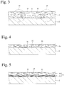
- the dispersion layer 3a may be spontaneously dried, it may be heated to such an extent as not to deform the plastic film, to finish the application step in a short period of time.
- the heating temperature is determined depending on the boiling point of an organic solvent used. For example, when methyl ethyl ketone is used, the heating temperature is preferably 30-100°C, more preferably 50-80°C. Drying need not be conducted to completely evaporate an organic solvent from the dispersion layer 3a, but may be conducted to such an extent that fine graphene particles and carbon nanotube are not freed out of the dried layer in the next application step.
- a new dispersion layer 3b is formed without substantially dissolving the first mixture layer 3a'.
- the dispersion layer 3b is dried, it becomes a second mixture layer integral with the first mixture layer 3a'.
- the repetition of such cycle of applying and drying a dispersion plural times provides a relatively thick, integral mixture layer, in which fine graphene particles are aligned in parallel, and carbon nanotube is uniformly dispersed.
- the number of cycles of applying and drying a dispersion is determined depending on the thickness of a mixture layer to be formed.
- each first plastic film 12a, 12b is fed intermittently to form a laminated film 1' having a mixture layer 11 between a pair of first plastic films 12a, 12b.
- a laminated film 1' obtained by passing between the laminating rolls 46a, 46b should be heat-pressed by plural pairs of heat-pressing rolls 47a, 47b, 48a, 48b arranged downstream of the rolls 46a, 46b.
- the heat-pressing conditions are preferably a temperature of 100-250°C and pressure of 20 MPa (about 200 kgf/cm 2 ) or more.
- the heat-pressing temperature is preferably 120-200°C, more preferably 150-180°C.
- the heat-pressing pressure is less than 20 MPa, the resultant mixture layer 11 does not have a sufficient density.
- the heat-pressed mixture layer 11 may be cut to a predetermined shape and size along the broken line 111 before burning, for example, as shown in Fig. 7 .
- the burning of the mixture layer 11 is preferably conducted by (a) ejecting flame onto the mixture layer 11, or by (b) exposing the mixture layer 11 to high temperatures of 500°C or higher in the air, in vacuum, or in an inert gas.
- the cut mixture layer 112 When burned by flame, for example, as shown in Fig. 8(a) , the cut mixture layer 112 is placed on a wire net 113, and burned by flame at about 900-1200°C ejected from a burner 114.
- One surface of the mixture layer 112 may be burned, but it is preferable to burn both surfaces of the mixture layer 112.
- the binder resin is burned out in the mixture layer 112 exposed to flame ejected from the burner 114.
- the flame-ejecting time is preferably as short as several seconds.
- the heating temperature is preferably 500-700°C, more preferably 500-650°C, to prevent excessive burning of fine graphene particles and carbon nanotube.
- the binder resin is burned out or carbonized by the burning of the mixture layer. Because of volume decrease by the burning or carbonization of the binder resin, pressing to eliminate voids makes fine graphene particles and carbon nanotube much denser, thereby obtaining a heat-conductive layer 10 with high thermal conductivity.
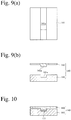
- a die 140 comprising a lower die part 141 having a cavity 141a, and an upper die part 142 having a projection 142a received in the cavity 141a is used as shown in Figs. 9(a) and 9(b) .
- the cavity 141a longitudinally extends from one side to the other in the lower die part 141, with the same width as that of the burnt layer 131.
- the upper die part 142 is placed on the lower die part 141, such that the projection 142a covers the burnt layer 131.
- the thickness of the burnt layer 131 is sufficiently smaller than the depth of the cavity 141a, the projection 142a of the upper die part 142 enters the cavity 141a, thereby accurately positioning the upper die part 142 relative to the lower die part 141.
- a pressing means for densifying the burnt layer 131 comprises (a) a die 140 comprising a lower die part 141 and an upper die part 142 combined to sandwich the burnt layer 131, (b) a pair of rolls 103a, 103b for pressing the die 140, (c) guide plates 143a, 143b positioned upstream and downstream of the gap of the rolls 103a, 103b, and (d) a means (not shown) for reciprocating the die 140 along the guide plates 143a, 143b such that the die 140 passes through the gap of a pair of pressing rolls 103a, 103b.
- the lower pressing roll 103a is a driving roll
- the upper pressing roll 103b is a follower roll.
- the follower roll 103b having a slightly smaller diameter than that of the driving roll 103a
- the upper die part 142 is free from being curved by pressing.
- a reciprocation range of the die 140 is sufficiently longer than the burnt layer 131. Reciprocation may be conducted once or several times.
- a pressing force applied to the die 140 may be increased as passing through the gap of the pressing rolls 103a, 103b.
- the burnt layer 131 is turned to a heat-conductive layer 10 by pressing the die 140.
- the vibration frequency is preferably 50-500 Hz, more preferably 100-300 Hz.
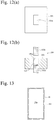
- Figs. 12(a) and 12(b) show another example of dies used in the pressing means for densifying the burnt layer.
- This die 150 comprises a die body 151 having a vertically penetrating cavity 151a, an upper punch 152a inserted into the cavity 151a from above, and a lower punch 152b inserted into the cavity 151a from below. After the lower punch 152b is inserted into the cavity 151 a, a burnt layer 131 is put on the lower punch 152b, and the upper punch 152a inserted into cavity 151a from above is moved downward to press the burnt layer 131 for densification. With the same vibration as above applied to the upper punch 152a, a larger pressing effect is obtained.
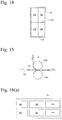
- the edge portions are cut off from the heat-conductive layer 10 along the broken line 161 to obtain a heat-conductive layer 10a of a predetermined size as shown in Fig. 13 , or ( 2 ) the heat-conductive layer 10 is divided along the broken lines 162 to heat-conductive layers 10b of a final size as shown in Fig. 14 .
- the size, shape and number of the heat-conductive layers 10b may be arbitrarily determined.
- a second plastic film 13a to which the heat-conductive layers 10a are attached with predetermined intervals is laminated with another second plastic film 13b by a pair of rolls 102a, 102b, and the laminated film is cut in every heat-conductive layer 10a to obtain individual heat-dissipating films, as shown in Fig. 15 .
- the second plastic film 13a having an adhesive layer With the second plastic film 13a having an adhesive layer, the attached heat-conductive layers 10a are not displaced.
- the second plastic films 13a, 13b are preferably heat-laminated via the heat-conductive layers 10a.
- one second plastic film 13a to which pluralities of heat-conductive layers 10b are attached with predetermined intervals as shown in Fig. 16(a) , is first laminated with another second plastic film 13b by a pair of rolls 102a, 102b as shown in Fig. 17 , to obtain a laminated film shown in Fig. 18 .
- the laminated film is divided along the broken lines 163 to obtain individual heat-dissipating films.
- each heat-conductive layer 10a (10b) is sandwiched by a pair of second plastic films 13a, 13b, whose edge portions are heat-sealed.
- a dispersion comprising flake-like, fine graphene particles (H-25 available from XG Sciences, average diameter: 25 ⁇ m, and average thickness: about 15 nm), carbon nanotube (CNT, average diameter: 10-50 nm, and average length: about 25 ⁇ m), and polymethylmethacrylate (PMMA) in the proportion shown in Table 1 in an organic solvent (mixed solvent of xylene and isopropyl alcohol at a mass ratio of 6/4) was applied to aluminum-deposited surfaces of two aluminum-deposited polyethylene terephthalate (PET) films (first plastic films) 12a, 12b as thick as 30 ⁇ m, and dried at 40°C for 2 minutes to obtain each coating layer of fine graphene particles, carbon nanotube and PMMA having a thickness of 20 g/m 2 (expressed by the grams of fine graphene particles + carbon nanotube per 1 m 2 ).
- PET polyethylene terephthalate
- a pair of PET films 12a, 12b each having a mixture layer 11a, 11b were laminated at 120°C by a pair of rolls 46a, 46b, with the mixture layers 11a, 11b inside, and then heat-pressed at 150°C by plural pairs of heating rolls 47a, 47b, 48a, 48b under pressure of 20 MPa, to form a laminated film 1' comprising the mixture layer 11.
- the resultant heat-conductive layer 10 was cut to a predetermined size, its density, specific heat, and heat diffusivity (m 2 /s) in in-plane and thickness directions were measured.
- the thermal conductivity (W/mK) was determined from the product of heat diffusivity and heat capacity (density x specific heat).
- the density, and heat diffusivity and thermal conductivity in in-plane and thickness directions of the heat-conductive layers 10 are shown in Table 2.
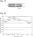
- the relation between the mass ratio of carbon nanotube/(fine graphene particles + carbon nanotube) and the in-plane thermal conductivity of the heat-conductive layer is shown in Fig. 20 . Table 2 No.
- the heat-conductive layers of Examples 1-5 in which the mass ratio of carbon nanotube/(fine graphene particles + carbon nanotube) was in a range of 0.05-0.2, were remarkably higher in thermal conductivity than the heat-conductive layer of Comparative Example 1 containing no carbon nanotube and the heat-conductive layer of Comparative Example 2 containing excessive carbon nanotube.
- Particularly low thermal conductivity of the heat-conductive layer of Comparative Example 2 appears to be due to the fact that excessive carbon nanotube was agglomerated.
- one PET film 13a to which a heat-conductive layer 10a was attached, was laminated with another PET film 13b by a pair of rolls 102a, 102b.
- the laminated film 1' was cut to individual heat-dissipating films.
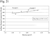
- Heat-conductive layers having different densities were produced by changing the pressing pressure of the burnt layer having the same composition as in Example 5.
- the relation between the density and in-plane thermal conductivity of the heat-conductive layer is shown in Fig. 21 . It is clear from Fig. 21 that the increased density leads to the increased in-plane thermal conductivity.
Landscapes
- Engineering & Computer Science (AREA)
- Physics & Mathematics (AREA)
- Chemical & Material Sciences (AREA)
- Mechanical Engineering (AREA)
- Thermal Sciences (AREA)
- Composite Materials (AREA)
- Mathematical Physics (AREA)
- General Engineering & Computer Science (AREA)
- Combustion & Propulsion (AREA)
- Materials Engineering (AREA)
- Organic Chemistry (AREA)
- Chemical Kinetics & Catalysis (AREA)
- Microelectronics & Electronic Packaging (AREA)
- Carbon And Carbon Compounds (AREA)
- Laminated Bodies (AREA)
- Cooling Or The Like Of Semiconductors Or Solid State Devices (AREA)
- Coating Of Shaped Articles Made Of Macromolecular Substances (AREA)
- Manufacture Of Macromolecular Shaped Articles (AREA)
Claims (8)
- Wärme ableitende Folie (1), umfassend eine wärmeleitfähige Schicht (10), umfassend- feine Graphen-Teilchen (31) und Kohlenstoff-Nanoröhrchen (32) einheitlich darin dispergiert; wobeiein Massenverhältnis von Kohlenstoff-Nanoröhrchen (32) zu der Gesamtmenge feiner Graphen-Teilchen (31) und Kohlenstoff-Nanoröhrchen (32) 0,05 bis 0,2 ist;
die feinen Graphen-Teilchen (31) im Wesentlichen mit der wärmeleitfähigen Schicht (10) ausgerichtet sind; und
die wärmeleitfähige Schicht (10) eine Dichte von 1,9 g/cm3 oder mehr und eine thermische Leitfähigkeit von 600 W/mK oder mehr aufweist. - Wärme ableitende Folie (1) nach Anspruch 1, worin die wärmeleitfähige Schicht (10) eine Dicke von 50 bis 250 g/m2 (ausgedrückt durch das Gesamtgewicht der feinen Graphen-Teilchen und der Kohlenstoff-Nanoröhrchen pro 1 m2) aufweist.
- Wärme ableitende Folie (1) nach Anspruch 1 oder 2, worin die wärmeleitfähige Schicht (10) mit Kunststoff-Filmen (2, 2) bedeckt ist.
- Verfahren zur Herstellung einer Wärme ableitenden Folie (1), umfassend eine wärmeleitfähige Schicht (10), umfassend- feine Graphen-Teilchen (31) und Kohlenstoff-Nanoröhrchen (32) einheitlich darin dispergiert; wobeiein Massenverhältnis von Kohlenstoff-Nanoröhrchen (32) zu der Gesamtmenge feiner Graphen-Teilchen (31) und Kohlenstoff-Nanoröhrchen (32) 0,05 bis 0,2 ist; und
die feinen Graphen-Teilchen (31) im Wesentlichen mit der wärmeleitfähigen Schicht (10) ausgerichtet sind;
welches die Schritte umfaßt, daß man(1) eine Mischungs-Schicht (11), die feine Graphen-Teilchen (31) und Kohlenstoff-Nanoröhrchen (32) in dem Massenverhältnis umfaßt, und darüber hinaus ein Binderharz in einem Massenverhältnis von 0,01 - 0,1 pro Gesamtmenge der feinen Graphen-Teilchen (31) und der Kohlenstoff-Nanoröhrchen (32) umfaßt, zwischen ein Paar erster Kunststoff-Filme (12a, 12b) sandwichartig einlegt, um einen laminierten Film (1') zu bilden;(2) den laminierten Film (1') heißpresst, um die Mischungs-Schicht (11) zu verdichten;(3) die Mischungsschicht (11), die durch Abziehen der ersten Kunststoff-Filme (12a, 12b) freigelegt wurde, einem Brennen aussetzt;(4) die gebrannte Schicht (131) presst, um eine verdichtete wärmeleitfähige Schicht (10) bereitzustellen; und(5) die verdichtete wärmeleitfähige Schicht (10) mit zweiten Kunststoff-Filmen (13a, 13b) oder einem isolierenden Harz bedeckt. - Verfahren zur Herstellung eines Hitze ableitenden Films (1) nach Anspruch 4, worin ein Schritt des Aufbringens einer Dispersion, die umfaßt 5 - 25 Massen-% pro Gesamtmenge feiner Graphen-Teilchen (31) und Kohlenstoff-Nanoröhrchen (32), und 0,05 - 2,5 Massen-% eines Binderharzes in einem organischen Lösungsmittel, wobei ein Massenverhältnis von Binderharz/(feine Graphen-Teilchen + Kohlenstoff-Nanoröhrchen) 0,01 - 0,1 ist, auf eine Oberfläche eines jeden ersten Kunststoff-Films und diesen trocknet, mehrere Male wiederholt wird, um die Mischungsschicht (11) zu bilden.
- Verfahren zur Herstellung eines Hitze ableitenden Films (1) nach Anspruch 4 oder 5, worin die Menge der Dispersion, die pro Vorgang aufgebracht wird, 5 - 30 g/m2 (ausgedrückt durch das Gesamtgewicht feiner Graphen-Teilchen und Kohlenstoff-Nanoröhrchen pro 1 m2) ist.
- Verfahren zur Herstellung eines Hitze ableitenden Films (1) nach irgendeinem der Ansprüche 4 bis 6, worin der erste Kunststoff-Film eine Trennschicht auf der mit der Dispersion zu beschichtenden Oberfläche aufweist.
- Verfahren zur Herstellung eines Hitze ableitenden Films (1) nach irgendeinem der Ansprüche 4 bis 7, worin der laminierte Film durch wenigstens ein Paar Wärmewalzen durchgeführt wird, um den laminierten Film (1') heißzupressen.
Applications Claiming Priority (1)
| Application Number | Priority Date | Filing Date | Title |
|---|---|---|---|
| JP2013222128A JP5490957B1 (ja) | 2013-10-25 | 2013-10-25 | 放熱フィルム、並びにその製造方法及び装置 |
Publications (2)
| Publication Number | Publication Date |
|---|---|
| EP2865729A1 EP2865729A1 (de) | 2015-04-29 |
| EP2865729B1 true EP2865729B1 (de) | 2017-08-09 |
Family
ID=50792270
Family Applications (1)
| Application Number | Title | Priority Date | Filing Date |
|---|---|---|---|
| EP14188322.3A Not-in-force EP2865729B1 (de) | 2013-10-25 | 2014-10-09 | Wärmeableitende folie sowie deren herstellungsverfahren |
Country Status (6)
| Country | Link |
|---|---|
| US (2) | US20150118482A1 (de) |
| EP (1) | EP2865729B1 (de) |
| JP (1) | JP5490957B1 (de) |
| KR (1) | KR20150048074A (de) |
| CN (2) | CN108189490B (de) |
| TW (1) | TWI637049B (de) |
Families Citing this family (50)
| Publication number | Priority date | Publication date | Assignee | Title |
|---|---|---|---|---|
| JP6472384B2 (ja) * | 2013-11-19 | 2019-02-20 | 日本碍子株式会社 | 断熱膜、および断熱膜構造 |
| JP6562841B2 (ja) * | 2014-01-31 | 2019-08-21 | 日本碍子株式会社 | 多孔質板状フィラー |
| JP6448558B2 (ja) * | 2014-02-10 | 2019-01-09 | 日本碍子株式会社 | 多孔質板状フィラー集合体及びその製造方法、並びに多孔質板状フィラー集合体を含む断熱膜 |
| WO2015163249A1 (ja) * | 2014-04-23 | 2015-10-29 | 日本碍子株式会社 | 多孔質板状フィラー、その製造方法、及び断熱膜 |
| JP5582553B1 (ja) * | 2014-05-02 | 2014-09-03 | 清二 加川 | 高熱伝導率の放熱シート及びその製造方法 |
| US9713820B2 (en) * | 2014-06-02 | 2017-07-25 | The Boeing Company | System and method of forming a nanotube mesh structure |
| US11857004B2 (en) * | 2014-11-14 | 2024-01-02 | Gentherm Incorporated | Heating and cooling technologies |
| KR101644559B1 (ko) * | 2015-01-13 | 2016-08-02 | 한국과학기술연구원 | 고열전도성 하이브리드 시트 및 그 제조방법 |
| WO2016182018A1 (ja) * | 2015-05-13 | 2016-11-17 | 昭和電工株式会社 | カーボンナノチューブ複合シートの製造方法 |
| JP6455336B2 (ja) * | 2015-06-23 | 2019-01-23 | 日本ゼオン株式会社 | 熱伝導シートおよびその製造方法 |
| JP6543161B2 (ja) * | 2015-07-27 | 2019-07-10 | 積水化学工業株式会社 | 熱伝導部材、熱伝導部材積層体及び熱伝導部材成形体 |
| TWI690257B (zh) * | 2015-08-31 | 2020-04-01 | 英屬維爾京群島商新奈科技有限公司 | 導熱結構及散熱裝置 |
| CN105101755B (zh) * | 2015-08-31 | 2017-12-15 | 天奈(镇江)材料科技有限公司 | 导热结构及散热装置 |
| JP2017056579A (ja) * | 2015-09-15 | 2017-03-23 | 日本ゼオン株式会社 | カーボンナノチューブ積層シートの製造方法 |
| WO2017069265A1 (ja) * | 2015-10-23 | 2017-04-27 | 日本碍子株式会社 | 排熱回収器 |
| CN105523547B (zh) * | 2016-01-25 | 2017-09-29 | 浙江大学 | 一种超柔性高导热石墨烯膜及其制备方法 |
| WO2017128944A1 (zh) * | 2016-01-29 | 2017-08-03 | 中国科学院苏州纳米技术与纳米仿生研究所 | 碳纳米管聚集体于制备纳米碳抗冲击材料中的用途及其制备方法 |
| TWI627894B (zh) * | 2016-02-15 | 2018-06-21 | 鈺冠科技股份有限公司 | 使用奈米材料的電磁波防護帶 |
| CN105702644A (zh) * | 2016-02-18 | 2016-06-22 | 东莞迪蜂金属材料科技有限公司 | 一种铝合金石墨烯散热制品及制备方法 |
| CN105802589A (zh) * | 2016-05-09 | 2016-07-27 | 中国石油大学(北京) | 一种高强度导热膜及其制备方法 |
| CN105899053B (zh) * | 2016-06-23 | 2019-02-01 | 深圳天元羲王材料科技有限公司 | 一种石墨烯散热薄膜 |
| TWI602499B (zh) * | 2016-08-08 | 2017-10-11 | 鈺冠科技股份有限公司 | 使用奈米材料的複合式導熱片及其製作方法 |
| US10117355B2 (en) * | 2016-08-29 | 2018-10-30 | Chemnova Technologies, Inc. | Heat dissipation foil and methods of heat dissipation |
| CN106166865A (zh) * | 2016-08-30 | 2016-11-30 | 无锡市中星工业胶带有限公司 | 一种阻燃抗静电bopet复合膜 |
| CN106183214A (zh) * | 2016-08-30 | 2016-12-07 | 无锡市中星工业胶带有限公司 | 一种抗紫外、耐热bopet膜 |
| CN106550585A (zh) * | 2016-09-13 | 2017-03-29 | 华为机器有限公司 | 一种散热片及其制备方法和通信设备 |
| WO2018067104A1 (en) | 2016-10-03 | 2018-04-12 | Hewlett-Packard Development Company, L.P. | Multilayer housings |
| TWI605749B (zh) * | 2016-12-15 | 2017-11-11 | 台虹科技股份有限公司 | 電磁干擾屏蔽膜 |
| CN106802106A (zh) * | 2017-02-21 | 2017-06-06 | 广东万家乐燃气具有限公司 | 一种换热高效防腐蚀的带石墨烯保护膜的换热器制备方法 |
| JP2020523233A (ja) | 2017-07-13 | 2020-08-06 | ヒューレット−パッカード デベロップメント カンパニー エル.ピー.Hewlett‐Packard Development Company, L.P. | コーティング組成物 |
| CN207099513U (zh) * | 2017-09-05 | 2018-03-13 | 陈庆洪 | 一种散热功能良好的防护等级达65级及以上的电气机箱 |
| US10872840B2 (en) * | 2018-01-19 | 2020-12-22 | Wuhan China Star Optoelectronics Semiconductor Display Technology Co., Ltd. | Thermal conductive sheet |
| JP7139627B2 (ja) * | 2018-03-07 | 2022-09-21 | 日本ゼオン株式会社 | 不織布およびその製造方法 |
| CN108910863B (zh) * | 2018-06-26 | 2020-05-15 | 中科钢研节能科技有限公司 | 一种石墨烯导热膜及其制备方法 |
| CN121230238A (zh) | 2018-11-30 | 2025-12-30 | 金瑟姆股份公司 | 热电调节系统和方法 |
| KR102564273B1 (ko) * | 2018-12-19 | 2023-08-07 | 삼성전자주식회사 | 디스플레이장치 |
| CN109776103B (zh) * | 2019-01-17 | 2021-07-09 | 郑州中科新兴产业技术研究院 | 一种三维石墨烯/碳纳米管复合散热材料的制备方法 |
| CN110564335A (zh) * | 2019-08-13 | 2019-12-13 | 深圳烯湾科技有限公司 | 碳纳米管电磁屏蔽散热薄膜及其制备方法 |
| US11483948B2 (en) | 2019-08-28 | 2022-10-25 | Laird Technologies, Inc. | Thermal interface materials including memory foam cores |
| CN111154461B (zh) * | 2020-01-06 | 2021-10-08 | 宁波石墨烯创新中心有限公司 | 定向组装石墨烯、石墨烯-碳纳米管复合导热膜及其制备方法 |
| US11248852B2 (en) * | 2020-07-06 | 2022-02-15 | Dell Products L.P. | Graphite thermal cable and method for implementing same |
| WO2022079914A1 (ja) * | 2020-10-16 | 2022-04-21 | 昭和電工マテリアルズ株式会社 | 熱伝導シート保持体及び放熱装置の製造方法 |
| US12209664B2 (en) | 2020-12-10 | 2025-01-28 | Laird Technologies (Shenzhen) Ltd. | Electrically and thermally conductive gaskets |
| EP4013203B1 (de) | 2020-12-10 | 2024-07-31 | Laird Technologies (Shenzhen) Ltd. | Elektrisch und thermisch leitende dichtungen |
| US12611909B2 (en) | 2021-03-18 | 2026-04-28 | Gentherm Incorporated | Preconditioning surfaces using intelligent thermal effectors |
| US12552223B2 (en) | 2021-03-18 | 2026-02-17 | Gentherm Incorporated | Optimal control of convective thermal devices |
| CN117396542A (zh) | 2021-05-26 | 2024-01-12 | 日产自动车株式会社 | 导热膜以及使用了该导热膜的散热结构体 |
| EP4349889A4 (de) * | 2021-05-26 | 2024-06-26 | Nissan Motor Co., Ltd. | Wärmeleitfolie und wärmeableitende struktur damit |
| KR102729810B1 (ko) * | 2021-11-10 | 2024-11-14 | (주)이녹스첨단소재 | 플렉서블 방열 시트 및 이를 포함하는 디스플레이 부품 |
| CN118578747B (zh) * | 2024-06-24 | 2025-12-19 | 吉林大学 | 一种复合膜及其制备方法和应用 |
Citations (1)
| Publication number | Priority date | Publication date | Assignee | Title |
|---|---|---|---|---|
| EP3034292A1 (de) * | 2013-08-12 | 2016-06-22 | Seiji Kagawa | Wärmeleitende folie sowie verfahren und vorrichtung zur herstellung davon |
Family Cites Families (13)
| Publication number | Priority date | Publication date | Assignee | Title |
|---|---|---|---|---|
| DE19828790A1 (de) * | 1998-06-27 | 1999-12-30 | Sgl Technik Gmbh | Packungsgarn aus Graphit- und Metallfolie |
| JP2006306068A (ja) | 2005-03-29 | 2006-11-09 | Kaneka Corp | 熱伝導シート |
| JP5116082B2 (ja) * | 2007-04-17 | 2013-01-09 | 住友精密工業株式会社 | 高熱伝導複合材料 |
| US20100000441A1 (en) * | 2008-07-01 | 2010-01-07 | Jang Bor Z | Nano graphene platelet-based conductive inks |
| JP2010253730A (ja) * | 2009-04-22 | 2010-11-11 | Sumitomo Electric Ind Ltd | 放熱材料、プリント基板およびプリント基板の製造方法 |
| KR101470524B1 (ko) * | 2009-06-30 | 2014-12-08 | 한화케미칼 주식회사 | 혼화성이 증대된 복합탄소소재 및 이의 연속적인 제조 방법 |
| WO2011055961A2 (ko) * | 2009-11-03 | 2011-05-12 | Yu Jong-Sam | 팽창흑연시트에 혼합분산용액을 코팅한 혼합카본시트의 제조방법 |
| JP5747421B2 (ja) * | 2010-12-02 | 2015-07-15 | 国立研究開発法人物質・材料研究機構 | カーボンナノチューブ連結のグラフェンシートフィルムとその製造方法及びそれを用いたグラフェンシートキャパシター |
| JP5691524B2 (ja) | 2011-01-05 | 2015-04-01 | ソニー株式会社 | グラフェン膜の転写方法および透明導電膜の製造方法 |
| JP2012211259A (ja) | 2011-03-31 | 2012-11-01 | Panasonic Corp | 熱伝導シート |
| EP2562766A1 (de) * | 2011-08-22 | 2013-02-27 | Bayer MaterialScience AG | Kohlenstoffnanoröhren und Graphenplättchen umfassende Dispersionen |
| CN103219066B (zh) * | 2012-01-19 | 2016-08-03 | 中国科学院上海硅酸盐研究所 | 二维石墨烯与一维纳米线复合的柔性导电薄膜及其制备方法 |
| TWI472484B (zh) * | 2012-10-09 | 2015-02-11 | Taiwan Textile Res Inst | 順向排列石墨烯片高分子複合材料及其製造方法 |
-
2013
- 2013-10-25 JP JP2013222128A patent/JP5490957B1/ja not_active Expired - Fee Related
-
2014
- 2014-10-09 EP EP14188322.3A patent/EP2865729B1/de not_active Not-in-force
- 2014-10-24 KR KR1020140145366A patent/KR20150048074A/ko not_active Withdrawn
- 2014-10-24 CN CN201810125452.0A patent/CN108189490B/zh not_active Expired - Fee Related
- 2014-10-24 US US14/523,381 patent/US20150118482A1/en not_active Abandoned
- 2014-10-24 CN CN201410575563.3A patent/CN104582428B/zh not_active Expired - Fee Related
- 2014-10-24 TW TW103136822A patent/TWI637049B/zh active
-
2019
- 2019-07-18 US US16/515,682 patent/US20190338176A1/en not_active Abandoned
Patent Citations (1)
| Publication number | Priority date | Publication date | Assignee | Title |
|---|---|---|---|---|
| EP3034292A1 (de) * | 2013-08-12 | 2016-06-22 | Seiji Kagawa | Wärmeleitende folie sowie verfahren und vorrichtung zur herstellung davon |
Also Published As
| Publication number | Publication date |
|---|---|
| TWI637049B (zh) | 2018-10-01 |
| CN104582428B (zh) | 2019-03-19 |
| US20190338176A1 (en) | 2019-11-07 |
| CN108189490B (zh) | 2020-04-03 |
| US20150118482A1 (en) | 2015-04-30 |
| JP2015084359A (ja) | 2015-04-30 |
| CN104582428A (zh) | 2015-04-29 |
| TW201534710A (zh) | 2015-09-16 |
| KR20150048074A (ko) | 2015-05-06 |
| JP5490957B1 (ja) | 2014-05-14 |
| CN108189490A (zh) | 2018-06-22 |
| EP2865729A1 (de) | 2015-04-29 |
Similar Documents
| Publication | Publication Date | Title |
|---|---|---|
| EP2865729B1 (de) | Wärmeableitende folie sowie deren herstellungsverfahren | |
| US10538054B2 (en) | Heat-dissipating film, and its production method and apparatus | |
| US10609810B2 (en) | Method for producing heat-dissipating sheet having high thermal conductivity | |
| EP3377441B1 (de) | Hochleitfähiger graphen-metall-verbundwerkstoff und verfahren zur herstellung | |
| JP5980673B2 (ja) | 放熱フィルム、並びにその製造方法及び装置 | |
| US10005943B2 (en) | Heat-dissipating sheet having high thermal conductivity and its production method | |
| KR20180099695A (ko) | 카본나노튜브 복합재 및 카본나노튜브 복합재의 제조방법 | |
| CN101371385A (zh) | 燃料电池双极板、制备该燃料电池双极板的方法以及包含该双极板的燃料电池 | |
| TW202120775A (zh) | 石墨片的製造方法 | |
| WO2018088045A1 (ja) | 金属-炭素粒子複合材及びその製造方法 | |
| US20190001652A1 (en) | Method for producing metal-carbon fiber composite material | |
| JP5882936B2 (ja) | 放熱フィルムの製造方法及び装置 | |
| JP2019026920A (ja) | 金属−炭素粒子複合材の製造方法 |
Legal Events
| Date | Code | Title | Description |
|---|---|---|---|
| PUAI | Public reference made under article 153(3) epc to a published international application that has entered the european phase |
Free format text: ORIGINAL CODE: 0009012 |
|
| 17P | Request for examination filed |
Effective date: 20141009 |
|
| AK | Designated contracting states |
Kind code of ref document: A1 Designated state(s): AL AT BE BG CH CY CZ DE DK EE ES FI FR GB GR HR HU IE IS IT LI LT LU LV MC MK MT NL NO PL PT RO RS SE SI SK SM TR |
|
| AX | Request for extension of the european patent |
Extension state: BA ME |
|
| R17P | Request for examination filed (corrected) |
Effective date: 20151029 |
|
| RBV | Designated contracting states (corrected) |
Designated state(s): AL AT BE BG CH CY CZ DE DK EE ES FI FR GB GR HR HU IE IS IT LI LT LU LV MC MK MT NL NO PL PT RO RS SE SI SK SM TR |
|
| 17Q | First examination report despatched |
Effective date: 20160714 |
|
| GRAP | Despatch of communication of intention to grant a patent |
Free format text: ORIGINAL CODE: EPIDOSNIGR1 |
|
| INTG | Intention to grant announced |
Effective date: 20170317 |
|
| GRAS | Grant fee paid |
Free format text: ORIGINAL CODE: EPIDOSNIGR3 |
|
| GRAA | (expected) grant |
Free format text: ORIGINAL CODE: 0009210 |
|
| AK | Designated contracting states |
Kind code of ref document: B1 Designated state(s): AL AT BE BG CH CY CZ DE DK EE ES FI FR GB GR HR HU IE IS IT LI LT LU LV MC MK MT NL NO PL PT RO RS SE SI SK SM TR |
|
| REG | Reference to a national code |
Ref country code: GB Ref legal event code: FG4D |
|
| REG | Reference to a national code |
Ref country code: CH Ref legal event code: EP Ref country code: AT Ref legal event code: REF Ref document number: 916818 Country of ref document: AT Kind code of ref document: T Effective date: 20170815 |
|
| REG | Reference to a national code |
Ref country code: IE Ref legal event code: FG4D |
|
| REG | Reference to a national code |
Ref country code: DE Ref legal event code: R096 Ref document number: 602014012794 Country of ref document: DE |
|
| REG | Reference to a national code |
Ref country code: NL Ref legal event code: MP Effective date: 20170809 |
|
| REG | Reference to a national code |
Ref country code: LT Ref legal event code: MG4D |
|
| REG | Reference to a national code |
Ref country code: FR Ref legal event code: PLFP Year of fee payment: 4 |
|
| REG | Reference to a national code |
Ref country code: AT Ref legal event code: MK05 Ref document number: 916818 Country of ref document: AT Kind code of ref document: T Effective date: 20170809 |
|
| PG25 | Lapsed in a contracting state [announced via postgrant information from national office to epo] |
Ref country code: SE Free format text: LAPSE BECAUSE OF FAILURE TO SUBMIT A TRANSLATION OF THE DESCRIPTION OR TO PAY THE FEE WITHIN THE PRESCRIBED TIME-LIMIT Effective date: 20170809 Ref country code: HR Free format text: LAPSE BECAUSE OF FAILURE TO SUBMIT A TRANSLATION OF THE DESCRIPTION OR TO PAY THE FEE WITHIN THE PRESCRIBED TIME-LIMIT Effective date: 20170809 Ref country code: AT Free format text: LAPSE BECAUSE OF FAILURE TO SUBMIT A TRANSLATION OF THE DESCRIPTION OR TO PAY THE FEE WITHIN THE PRESCRIBED TIME-LIMIT Effective date: 20170809 Ref country code: FI Free format text: LAPSE BECAUSE OF FAILURE TO SUBMIT A TRANSLATION OF THE DESCRIPTION OR TO PAY THE FEE WITHIN THE PRESCRIBED TIME-LIMIT Effective date: 20170809 Ref country code: NO Free format text: LAPSE BECAUSE OF FAILURE TO SUBMIT A TRANSLATION OF THE DESCRIPTION OR TO PAY THE FEE WITHIN THE PRESCRIBED TIME-LIMIT Effective date: 20171109 Ref country code: LT Free format text: LAPSE BECAUSE OF FAILURE TO SUBMIT A TRANSLATION OF THE DESCRIPTION OR TO PAY THE FEE WITHIN THE PRESCRIBED TIME-LIMIT Effective date: 20170809 Ref country code: NL Free format text: LAPSE BECAUSE OF FAILURE TO SUBMIT A TRANSLATION OF THE DESCRIPTION OR TO PAY THE FEE WITHIN THE PRESCRIBED TIME-LIMIT Effective date: 20170809 |
|
| PG25 | Lapsed in a contracting state [announced via postgrant information from national office to epo] |
Ref country code: BG Free format text: LAPSE BECAUSE OF FAILURE TO SUBMIT A TRANSLATION OF THE DESCRIPTION OR TO PAY THE FEE WITHIN THE PRESCRIBED TIME-LIMIT Effective date: 20171109 Ref country code: IS Free format text: LAPSE BECAUSE OF FAILURE TO SUBMIT A TRANSLATION OF THE DESCRIPTION OR TO PAY THE FEE WITHIN THE PRESCRIBED TIME-LIMIT Effective date: 20171209 Ref country code: LV Free format text: LAPSE BECAUSE OF FAILURE TO SUBMIT A TRANSLATION OF THE DESCRIPTION OR TO PAY THE FEE WITHIN THE PRESCRIBED TIME-LIMIT Effective date: 20170809 Ref country code: RS Free format text: LAPSE BECAUSE OF FAILURE TO SUBMIT A TRANSLATION OF THE DESCRIPTION OR TO PAY THE FEE WITHIN THE PRESCRIBED TIME-LIMIT Effective date: 20170809 Ref country code: ES Free format text: LAPSE BECAUSE OF FAILURE TO SUBMIT A TRANSLATION OF THE DESCRIPTION OR TO PAY THE FEE WITHIN THE PRESCRIBED TIME-LIMIT Effective date: 20170809 Ref country code: GR Free format text: LAPSE BECAUSE OF FAILURE TO SUBMIT A TRANSLATION OF THE DESCRIPTION OR TO PAY THE FEE WITHIN THE PRESCRIBED TIME-LIMIT Effective date: 20171110 Ref country code: PL Free format text: LAPSE BECAUSE OF FAILURE TO SUBMIT A TRANSLATION OF THE DESCRIPTION OR TO PAY THE FEE WITHIN THE PRESCRIBED TIME-LIMIT Effective date: 20170809 |
|
| PG25 | Lapsed in a contracting state [announced via postgrant information from national office to epo] |
Ref country code: DK Free format text: LAPSE BECAUSE OF FAILURE TO SUBMIT A TRANSLATION OF THE DESCRIPTION OR TO PAY THE FEE WITHIN THE PRESCRIBED TIME-LIMIT Effective date: 20170809 Ref country code: CZ Free format text: LAPSE BECAUSE OF FAILURE TO SUBMIT A TRANSLATION OF THE DESCRIPTION OR TO PAY THE FEE WITHIN THE PRESCRIBED TIME-LIMIT Effective date: 20170809 Ref country code: RO Free format text: LAPSE BECAUSE OF FAILURE TO SUBMIT A TRANSLATION OF THE DESCRIPTION OR TO PAY THE FEE WITHIN THE PRESCRIBED TIME-LIMIT Effective date: 20170809 |
|
| REG | Reference to a national code |
Ref country code: DE Ref legal event code: R097 Ref document number: 602014012794 Country of ref document: DE |
|
| PG25 | Lapsed in a contracting state [announced via postgrant information from national office to epo] |
Ref country code: IT Free format text: LAPSE BECAUSE OF FAILURE TO SUBMIT A TRANSLATION OF THE DESCRIPTION OR TO PAY THE FEE WITHIN THE PRESCRIBED TIME-LIMIT Effective date: 20170809 Ref country code: MC Free format text: LAPSE BECAUSE OF FAILURE TO SUBMIT A TRANSLATION OF THE DESCRIPTION OR TO PAY THE FEE WITHIN THE PRESCRIBED TIME-LIMIT Effective date: 20170809 Ref country code: SM Free format text: LAPSE BECAUSE OF FAILURE TO SUBMIT A TRANSLATION OF THE DESCRIPTION OR TO PAY THE FEE WITHIN THE PRESCRIBED TIME-LIMIT Effective date: 20170809 Ref country code: SK Free format text: LAPSE BECAUSE OF FAILURE TO SUBMIT A TRANSLATION OF THE DESCRIPTION OR TO PAY THE FEE WITHIN THE PRESCRIBED TIME-LIMIT Effective date: 20170809 Ref country code: EE Free format text: LAPSE BECAUSE OF FAILURE TO SUBMIT A TRANSLATION OF THE DESCRIPTION OR TO PAY THE FEE WITHIN THE PRESCRIBED TIME-LIMIT Effective date: 20170809 |
|
| REG | Reference to a national code |
Ref country code: CH Ref legal event code: PL |
|
| PLBE | No opposition filed within time limit |
Free format text: ORIGINAL CODE: 0009261 |
|
| STAA | Information on the status of an ep patent application or granted ep patent |
Free format text: STATUS: NO OPPOSITION FILED WITHIN TIME LIMIT |
|
| 26N | No opposition filed |
Effective date: 20180511 |
|
| REG | Reference to a national code |
Ref country code: IE Ref legal event code: MM4A |
|
| PG25 | Lapsed in a contracting state [announced via postgrant information from national office to epo] |
Ref country code: LI Free format text: LAPSE BECAUSE OF NON-PAYMENT OF DUE FEES Effective date: 20171031 Ref country code: LU Free format text: LAPSE BECAUSE OF NON-PAYMENT OF DUE FEES Effective date: 20171009 Ref country code: CH Free format text: LAPSE BECAUSE OF NON-PAYMENT OF DUE FEES Effective date: 20171031 |
|
| REG | Reference to a national code |
Ref country code: BE Ref legal event code: MM Effective date: 20171031 |
|
| PG25 | Lapsed in a contracting state [announced via postgrant information from national office to epo] |
Ref country code: SI Free format text: LAPSE BECAUSE OF FAILURE TO SUBMIT A TRANSLATION OF THE DESCRIPTION OR TO PAY THE FEE WITHIN THE PRESCRIBED TIME-LIMIT Effective date: 20170809 Ref country code: BE Free format text: LAPSE BECAUSE OF NON-PAYMENT OF DUE FEES Effective date: 20171031 |
|
| PG25 | Lapsed in a contracting state [announced via postgrant information from national office to epo] |
Ref country code: MT Free format text: LAPSE BECAUSE OF NON-PAYMENT OF DUE FEES Effective date: 20171009 |
|
| REG | Reference to a national code |
Ref country code: FR Ref legal event code: PLFP Year of fee payment: 5 |
|
| PG25 | Lapsed in a contracting state [announced via postgrant information from national office to epo] |
Ref country code: IE Free format text: LAPSE BECAUSE OF NON-PAYMENT OF DUE FEES Effective date: 20171009 |
|
| PG25 | Lapsed in a contracting state [announced via postgrant information from national office to epo] |
Ref country code: HU Free format text: LAPSE BECAUSE OF FAILURE TO SUBMIT A TRANSLATION OF THE DESCRIPTION OR TO PAY THE FEE WITHIN THE PRESCRIBED TIME-LIMIT; INVALID AB INITIO Effective date: 20141009 |
|
| PG25 | Lapsed in a contracting state [announced via postgrant information from national office to epo] |
Ref country code: CY Free format text: LAPSE BECAUSE OF FAILURE TO SUBMIT A TRANSLATION OF THE DESCRIPTION OR TO PAY THE FEE WITHIN THE PRESCRIBED TIME-LIMIT Effective date: 20170809 |
|
| PG25 | Lapsed in a contracting state [announced via postgrant information from national office to epo] |
Ref country code: MK Free format text: LAPSE BECAUSE OF FAILURE TO SUBMIT A TRANSLATION OF THE DESCRIPTION OR TO PAY THE FEE WITHIN THE PRESCRIBED TIME-LIMIT Effective date: 20170809 |
|
| PG25 | Lapsed in a contracting state [announced via postgrant information from national office to epo] |
Ref country code: TR Free format text: LAPSE BECAUSE OF FAILURE TO SUBMIT A TRANSLATION OF THE DESCRIPTION OR TO PAY THE FEE WITHIN THE PRESCRIBED TIME-LIMIT Effective date: 20170809 |
|
| PG25 | Lapsed in a contracting state [announced via postgrant information from national office to epo] |
Ref country code: PT Free format text: LAPSE BECAUSE OF FAILURE TO SUBMIT A TRANSLATION OF THE DESCRIPTION OR TO PAY THE FEE WITHIN THE PRESCRIBED TIME-LIMIT Effective date: 20170809 |
|
| PG25 | Lapsed in a contracting state [announced via postgrant information from national office to epo] |
Ref country code: AL Free format text: LAPSE BECAUSE OF FAILURE TO SUBMIT A TRANSLATION OF THE DESCRIPTION OR TO PAY THE FEE WITHIN THE PRESCRIBED TIME-LIMIT Effective date: 20170809 |
|
| PGFP | Annual fee paid to national office [announced via postgrant information from national office to epo] |
Ref country code: GB Payment date: 20201022 Year of fee payment: 7 Ref country code: FR Payment date: 20201022 Year of fee payment: 7 Ref country code: DE Payment date: 20201022 Year of fee payment: 7 |
|
| REG | Reference to a national code |
Ref country code: DE Ref legal event code: R119 Ref document number: 602014012794 Country of ref document: DE |
|
| GBPC | Gb: european patent ceased through non-payment of renewal fee |
Effective date: 20211009 |
|
| PG25 | Lapsed in a contracting state [announced via postgrant information from national office to epo] |
Ref country code: GB Free format text: LAPSE BECAUSE OF NON-PAYMENT OF DUE FEES Effective date: 20211009 Ref country code: DE Free format text: LAPSE BECAUSE OF NON-PAYMENT OF DUE FEES Effective date: 20220503 |
|
| PG25 | Lapsed in a contracting state [announced via postgrant information from national office to epo] |
Ref country code: FR Free format text: LAPSE BECAUSE OF NON-PAYMENT OF DUE FEES Effective date: 20211031 |