EP2865824A2 - Vorrichtung zum Abdecken eines Schwimmbeckens - Google Patents
Vorrichtung zum Abdecken eines Schwimmbeckens Download PDFInfo
- Publication number
- EP2865824A2 EP2865824A2 EP20140188772 EP14188772A EP2865824A2 EP 2865824 A2 EP2865824 A2 EP 2865824A2 EP 20140188772 EP20140188772 EP 20140188772 EP 14188772 A EP14188772 A EP 14188772A EP 2865824 A2 EP2865824 A2 EP 2865824A2
- Authority
- EP
- European Patent Office
- Prior art keywords
- winding
- phase
- unwinding mechanism
- deployment
- unwinding
- Prior art date
- Legal status (The legal status is an assumption and is not a legal conclusion. Google has not performed a legal analysis and makes no representation as to the accuracy of the status listed.)
- Withdrawn
Links
- 238000004804 winding Methods 0.000 claims abstract description 100
- 239000000725 suspension Substances 0.000 claims abstract description 6
- 210000004197 pelvis Anatomy 0.000 claims description 4
- 230000003014 reinforcing effect Effects 0.000 description 3
- XLYOFNOQVPJJNP-UHFFFAOYSA-N water Substances O XLYOFNOQVPJJNP-UHFFFAOYSA-N 0.000 description 3
- 241001080024 Telles Species 0.000 description 2
- 230000000694 effects Effects 0.000 description 2
- 238000006243 chemical reaction Methods 0.000 description 1
- 238000013016 damping Methods 0.000 description 1
- 238000006073 displacement reaction Methods 0.000 description 1
- 230000005484 gravity Effects 0.000 description 1
- 238000012423 maintenance Methods 0.000 description 1
- 239000000463 material Substances 0.000 description 1
- 230000002028 premature Effects 0.000 description 1
- 238000011084 recovery Methods 0.000 description 1
- 238000010008 shearing Methods 0.000 description 1
- 238000004513 sizing Methods 0.000 description 1
- 230000009182 swimming Effects 0.000 description 1
- 230000007704 transition Effects 0.000 description 1
- 238000009736 wetting Methods 0.000 description 1
Images


Classifications
-
- E—FIXED CONSTRUCTIONS
- E04—BUILDING
- E04H—BUILDINGS OR LIKE STRUCTURES FOR PARTICULAR PURPOSES; SWIMMING OR SPLASH BATHS OR POOLS; MASTS; FENCING; TENTS OR CANOPIES, IN GENERAL
- E04H4/00—Swimming or splash baths or pools
- E04H4/06—Safety devices; Coverings for baths
- E04H4/10—Coverings of flexible material
- E04H4/101—Coverings of flexible material wound-up on a fixed axis
Definitions
- the present invention relates to the field of pool covers such as swimming pools and more particularly to a pool cover device.
- the retraction / deployment device comprises two arms interconnected by a connecting means.
- a sizing of the retraction / deployment device must take into account the value of this moment of force.
- the document EP 2 157 261 describes a basin covering device comprising a winding / unwinding mechanism of the cover held at its ends by means of lifting means designed to transmit to this mechanism a same angular position with respect to its longitudinal axis during its moving between its position retracted into a dwelling adjacent to the pool and its position above the pool.
- the document DE 4,109,584 discloses a pool cover winder whose arm, to which is attached a winding mechanism / unwinding cover, pivots about a pivot axis during the transition between its rest position and its implementation position.
- the document DE 2,938,496 describes a pool cover winder in a compartment intended to be immersed.
- the present invention aims to solve all or part of the disadvantages mentioned above.
- the present invention relates to a basin covering device of the aforementioned type characterized in that the retraction device is arranged so that the movement of the winding mechanism / unwinding between its first retracted position and its second deployed position has at least one so-called intermediate operating phase during which the winding / unwinding mechanism is in suspension on the retraction / deployment device.
- This arrangement makes it possible to increase the reliability of the covering device by limiting the effects of the moment of force generated by the weight of the winding / unwinding mechanism acting on the elements of the retraction / deployment device.
- the retraction / deployment device comprises a set of positioning means of the winding / unwinding mechanism between its first retracted position and its second deployed position.
- This arrangement makes it possible to adapt the movement of the winding / unwinding mechanism to the environment in which it is installed, in particular in order to reduce the size of the covering device or to obtain a particular movement.
- This arrangement makes it possible, on the one hand, to reduce the size of the covering device in the compartment when it is brought back to its first retracted position and, on the other hand, to limit the force exerted by the weight of the winding mechanism. unwinding on the first pivot link when it is arranged in its first phase of operation.
- the at least one first positioning means comprises at least one stop or at least one chain.
- said at least one first positioning means is arranged to stop the rotational movement of the at least one first arm articulated around the first pivot connection during the initial phase of deployment or final phase folding of the winding / unwinding mechanism.
- This arrangement makes it possible to arrange the winding / unwinding mechanism vertically of the basin so that, in the case of the use of a blade apron, the blades can slide freely on the surface of the water as and measuring the unwinding or winding of the blanket.
- the at least one second positioning means comprises at least one lever arm connected to a fixed point of the compartment via at least one flexible connection means or a jack.
- the at least one flexible connection means comprises a chain.
- the winding / unwinding mechanism is arranged at least partly in the vertical of the basin in the deployed position.
- a covering device 1 according to the invention is intended to be installed in a dry compartment 3 not immersed disposed in the extension of a basin 7.
- This covering device 1 comprises a winding / unwinding mechanism 4 of a cover 2, and a device for retracting / unfolding the winding / unwinding mechanism 4 in the or of the compartment 3.
- the winding / unwinding mechanism 4 has an elongated tubular shape so as to facilitate the winding and unwinding of the cover 2 around it.
- the cover 2 is connected by flexible straps to the winding / unwinding mechanism 4.
- the cover 2 can be made of flexible material, such as a tarpaulin or made in the form of a deck blade.
- the apron blade is particularly advantageous because it can be adapted to different forms of pools.
- compartment 3 can be covered with a removable hatch 8.
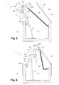
- the retraction / deployment device 15 is arranged to drive the winding / unwinding mechanism 4 between a first retracted position P1 illustrated in FIG. figure 2 wherein the winding / unwinding mechanism 4 of the cover 2 is folded inside the compartment 3 and a second deployed position P2 illustrated in FIG. figure 3 in which the winding / unwinding mechanism 4 of the cover 2 is arranged outside the compartment 3.
- the retraction / deployment device 15 comprises an assembly 10 of articulated arms connecting the winding / unwinding mechanism 4 to a fixed point of the compartment 3.
- the articulated arm assembly comprises a pair of first articulated arms 11a, 11b and a pair of second articulated arms 12a, 12b.
- Each first articulated arm 11a, 11b is integrally connected to a first of its two ends at one of the two ends of the winding / unwinding mechanism 4.
- the winding / unwinding mechanism 4 comprises a tubular motor.
- the part of the winding / unwinding mechanism 4 connected to the cover 2 can therefore rotate about the longitudinal axis of rotation of the winding / unwinding mechanism 4 only when the tubular motor is actuated or during a possible disengagement of the motor.
- the winding / unwinding mechanism 4 is firmly integral in rotation with each first articulated arm 11a, 11b between the first retracted position P1 and the second extended position P2 of the winding / unwinding mechanism 4.
- Each second articulated arm 12a, 12b is respectively connected firstly on a first of its two ends to the second end of one of the two first articulated arms 11a, 11b by a first pivot connection 13a, 13b and secondly on a second of its two ends at a fixed point of the compartment 3 by a second pivot connection 14a, 14b.
- the covering device 1 comprises a reinforcing tube 5 connecting the two second articulated arms 12a, 12b substantially at their mid-height, and a hydraulic jack 6 connected on the one hand to a fixed point of the compartment 3 on which it is supported and secondly to the reinforcing tube 5.
- a covering device 1 comprises a frame 30 that can be directly installed in the compartment 3, as well as two hydraulic cylinders 6a, 6b respectively bearing on the one hand on the chassis 30 and on the other hand on one of the second articulated arms 12a, 12b.
- the presence of the frame 30 makes it possible to stiffen the covering device 1 and to eliminate the reinforcing tube 5.
- the actuation of the hydraulic cylinder (s) 6, 6a, 6b enables the retraction / deployment device 15 to be set in motion so as to cause the winding / unwinding mechanism 4 between its first retracted position P1 and its second deployed position P2. .
- the mechanism 4 can unroll the cover 2 completely.
- the winding / unwinding mechanism 4 which remains connected to the cover 2 by the flexible straps can then be returned to its first retracted position P1 in the compartment 3 while the basin remains covered by the cover 2.
- the compartment 3 can then be closed by the hatch 8.
- the movement of the winding / unwinding mechanism 4 between its first retracted position P1 and its second deployed position P2 has several distinct operating phases ⁇ 1, ⁇ i, ⁇ 2.
- the first operating phase ⁇ 1 starts or ends respectively at the first retracted position P1 illustrated in FIG. figure 2 and corresponds to an initial deployment phase from this first retracted position P1 or to a final retreat phase towards this first retracted position P1, respectively.
- the second phase of operation ⁇ 2 ends or respectively starts at the second deployed position P2 illustrated in FIG. figure 3 and corresponds to a final phase of deployment towards this second deployed position P2 or respectively to a title phase of withdrawal from this second deployed position P2.
- the intermediate operating phase ⁇ i occurs between the first operating phase ⁇ 1 and the second operating phase ⁇ 2.
- the suspension of the winding / unwinding mechanism 4 thus tends to cancel the moment of force applying at the level of these same pivot links 13a, 13b.
- the retraction device 15 comprises a set of positioning means 20 for the movement of the winding / unwinding mechanism 4 between its first retracted position P1 and its second deployed position P2.
- the positioning means 20 comprise a pair of first positioning means 21a, 21b materialized by stops 21a, 21b.
- Each stop 21a, 21b is respectively fixed to one of the two first articulated arms 11a, 11b near the end of the first articulated arm 11a, 11b on which the winding / unwinding mechanism 4 is secured.
- abutments 21a, 21b have a long shape that extends substantially towards the pelvis 7 and transversely to a general direction of the first articulated arms 11a, 11b.
- Each of these two stops 21a, 21b arranged to limit the rotational movement of one of the two first articulated arms 11a, 11b around of the first pivot connection 13a, 13b during the first operating phase ⁇ 1 of the movement of the winding / unwinding mechanism 4.
- each of these stops 21a, 21b comprises a portion on its free end projecting towards the other stop 21a, 21b.
- This projecting end portion is arranged to abut against one of the two second articulated arms 12a, 12b at a given moment during the retraction of the winding / unwinding mechanism 4.
- This instant defines the limit between the first phase of operation ⁇ 1 and the intermediate phase of operation ⁇ i.
- the angle ⁇ defined by the angle between the main direction of the first articulated arms 11a, 11b and a vertical plane, is constant and substantially equal to 50 ° during the first phase of operation ⁇ 1 of the movement of the mechanism d winding / unfolding 4.
- the positioning means 20 also comprise a pair of second positioning means 22a, 22b embodied by lever arms.
- Each lever arm 22a, 22b is respectively fixed to one of the two first articulated arms 11a, 11b near the end of the first articulated arm 11a, 11b on which the first pivot link 13a, 13b acts.
- lever arms 22a, 22b have a long shape that extends substantially in the direction opposite the pelvis 7 and transversely to a general direction of the first articulated arms 11a, 11b.
- Each lever arm 22a, 22b comprises on its free end an orifice on which is hung a first end of a chain 9a, 9b.
- lever arms 22a, 22b associated with their respective chain 9a, 9b are arranged arranged to increase the rotational movement of the at least one first articulated arm 11a, 11b around the first pivot connection 13a, 13b towards the pool forward of the first pivot link 13a, 13b during the final deployment phase, and braking the rotational movement of the at least one first articulated arm 11a, 11b around the first pivot link 13a, 13b towards an opposite direction in the basin during the initial phase of withdrawal.
- the angular difference between the first articulated arms 11a, 11b and the second articulated arms 12a, 12b is thus increased during the final deployment phase.
- lever arms 22a, 22b are therefore rotated at a given moment during deployment of the winding / unwinding mechanism 4.
- This instant defines the limit between the second operating phase ⁇ 2 and the intermediate operating phase ⁇ i.
- these chains 9a, 9b may be replaced by jacks.
- the angle ⁇ evolves between 0 ° and 15 ° during a deployment during the second phase of operation ⁇ 2 of the movement of the winding / unwinding mechanism 4.
- the increase in the angular difference makes it possible to place the winding / unwinding mechanism 4 vertically of the basin 7 in its second deployed position so that during the unwinding of the blanket 2 it can reach directly by gravity water basin 7, and this even if the basin is equipped with coasters to the winding mechanism / unwinding 4 to be more advanced.
- the angle ⁇ is substantially zero during the intermediate phase ⁇ i of the movement of the winding / unwinding mechanism 4.
- the inertia of the winding / unwinding mechanism 4 can induce a pendulum or rocker movement to the winding / unwinding mechanism 4 during its displacement between its first retracted position P1 and its second deployed position P2.
- the positioning means 20 comprise a pair of first positioning means 21a, 21b materialized by chains 21a ', 21b' in place of the stops 21a, 21b of the first embodiment.
- Each of these chains 21 a ', 21 b' is respectively connected firstly to one of the two first articulated arms 11a, 11b and secondly to one of the two second articulated arms 12a, 12b.
- these chains 21a ', 21b' are arranged to limit the rotational movement of one of the two first articulated arms 11a, 11b around the first pivot connection 13a, 13b during the first operating phase ⁇ 1 of the movement of the winding / unwinding mechanism 4.
- these chains 21a ', 21b' are expanded leaving the winding / unwinding mechanism 4 in suspension on the retraction / deployment device 15.
- the covering device 1 comprises flexible flanges 31a, 31b disposed on the first articulated arms 11a, 11b intended to prevent the shearing of an element which could be arranged between the first arms articulated 11a, 11b and the second articulated arms 12a, 12b.
- the retraction / deployment device 15 may be equipped with a system comprising rollers at the level of the first pivot links 13a, 13b making it possible to raise the hatch 8 of the compartment 3 at the same time as the deployment of the winding / unwinding mechanism 4 of the compartment 3.
Landscapes
- Engineering & Computer Science (AREA)
- Architecture (AREA)
- Civil Engineering (AREA)
- Structural Engineering (AREA)
- Tents Or Canopies (AREA)
Applications Claiming Priority (1)
| Application Number | Priority Date | Filing Date | Title |
|---|---|---|---|
| FR1360020A FR3011867B1 (fr) | 2013-10-15 | 2013-10-15 | Dispositif de recouvrement de bassin |
Publications (2)
| Publication Number | Publication Date |
|---|---|
| EP2865824A2 true EP2865824A2 (de) | 2015-04-29 |
| EP2865824A3 EP2865824A3 (de) | 2015-12-09 |
Family
ID=49713329
Family Applications (1)
| Application Number | Title | Priority Date | Filing Date |
|---|---|---|---|
| EP14188772.9A Withdrawn EP2865824A3 (de) | 2013-10-15 | 2014-10-14 | Vorrichtung zum Abdecken eines Schwimmbeckens |
Country Status (2)
| Country | Link |
|---|---|
| EP (1) | EP2865824A3 (de) |
| FR (1) | FR3011867B1 (de) |
Cited By (2)
| Publication number | Priority date | Publication date | Assignee | Title |
|---|---|---|---|---|
| FR3066774A1 (fr) * | 2017-05-29 | 2018-11-30 | Sarl P.P.E.L. Paysage Piscine Environnement Loisirs | Systeme de rangement d'un volet de protection pour une piscine dans un coffre dote d'un couvercle articule |
| FR3148248A1 (fr) * | 2023-04-25 | 2024-11-01 | Thomas DEVIE | Dispositif de levage d'une plage disposee au-dessus d'un volet roulant pour couvrir une piscine |
Citations (4)
| Publication number | Priority date | Publication date | Assignee | Title |
|---|---|---|---|---|
| DE2938496A1 (de) | 1978-10-17 | 1980-04-24 | Glatz Ag | Abdeckvorrichtung fuer ein mit fluessigkeit gefuelltes becken |
| DE3142873A1 (de) | 1981-10-29 | 1983-05-11 | Robert 5060 Bergisch Gladbach Granderath | Vorrichtung zum abdecken von fluessigkeit enthaltenden becken |
| DE4109584A1 (de) | 1990-04-04 | 1991-10-10 | Aquamarq Ag | Aufrollvorrichtung fuer eine schwimmbeckenabdeckung |
| EP2157261A1 (de) | 2008-08-21 | 2010-02-24 | Cr2D | Abdeckungsvorrichtung für ein Becken, der Art eines Schwimmbeckens |
-
2013
- 2013-10-15 FR FR1360020A patent/FR3011867B1/fr active Active
-
2014
- 2014-10-14 EP EP14188772.9A patent/EP2865824A3/de not_active Withdrawn
Patent Citations (4)
| Publication number | Priority date | Publication date | Assignee | Title |
|---|---|---|---|---|
| DE2938496A1 (de) | 1978-10-17 | 1980-04-24 | Glatz Ag | Abdeckvorrichtung fuer ein mit fluessigkeit gefuelltes becken |
| DE3142873A1 (de) | 1981-10-29 | 1983-05-11 | Robert 5060 Bergisch Gladbach Granderath | Vorrichtung zum abdecken von fluessigkeit enthaltenden becken |
| DE4109584A1 (de) | 1990-04-04 | 1991-10-10 | Aquamarq Ag | Aufrollvorrichtung fuer eine schwimmbeckenabdeckung |
| EP2157261A1 (de) | 2008-08-21 | 2010-02-24 | Cr2D | Abdeckungsvorrichtung für ein Becken, der Art eines Schwimmbeckens |
Cited By (2)
| Publication number | Priority date | Publication date | Assignee | Title |
|---|---|---|---|---|
| FR3066774A1 (fr) * | 2017-05-29 | 2018-11-30 | Sarl P.P.E.L. Paysage Piscine Environnement Loisirs | Systeme de rangement d'un volet de protection pour une piscine dans un coffre dote d'un couvercle articule |
| FR3148248A1 (fr) * | 2023-04-25 | 2024-11-01 | Thomas DEVIE | Dispositif de levage d'une plage disposee au-dessus d'un volet roulant pour couvrir une piscine |
Also Published As
| Publication number | Publication date |
|---|---|
| FR3011867A1 (fr) | 2015-04-17 |
| FR3011867B1 (fr) | 2016-03-04 |
| EP2865824A3 (de) | 2015-12-09 |
Similar Documents
| Publication | Publication Date | Title |
|---|---|---|
| CA2799688C (fr) | Dispositif de deverrouillage d'un atterrisseur dans une position deployee et atterrisseur equipe d'un tel dispositif | |
| EP3347526B1 (de) | Bohrgerät | |
| FR2645089A1 (fr) | Plate-forme levante pour camion | |
| EP0280626B1 (de) | System zum Entfalten und Ablegen einer Brücke von einem Fahrzeug, wie einem Pionierpanzer, zur Ueberwindung von Hindernissen | |
| EP0069611A1 (de) | Hebevorrichtung für eine Plattform eines Kraftfahrzeuges | |
| FR2605619A1 (fr) | Engin repliable pour la manutention et le levage des charges | |
| EP2865824A2 (de) | Vorrichtung zum Abdecken eines Schwimmbeckens | |
| EP0041016B1 (de) | Automatisch hochziehbare Abdeckplatte | |
| FR2527187A1 (fr) | Rampe repliable, notamment pour des moyens de transport routiers | |
| EP3816091B1 (de) | Turmkran mit automatisch ein- und ausklappbarem gegenausleger | |
| EP0233090B1 (de) | Altglasbehälter | |
| EP3225582B1 (de) | Zusammenklappbare konstruktion zum zusammenbau eines turmkrans | |
| FR2493818A1 (fr) | Grue autotractee equipee de supports deployables de stabilisation et de jambes de force mobiles verticalement associees a ces derniers, et support deployable ainsi realise | |
| FR2684341A1 (fr) | Dispositif pour hisser ou retirer une echelle ou analogue sur ou a partir d'une galerie de toit d'un vehicule. | |
| EP0741206B1 (de) | Überlaufklappenwehr | |
| EP0775605B1 (de) | Sonnenschutzrolle mit Entfaltungsmechanismus durch Schwungstangen | |
| FR2800704A1 (fr) | Train d'atterrissage d'aeronef du type a relevage lateral | |
| FR2682712A1 (fr) | Dispositif de compensation pour tablier de volet roulant. | |
| FR2795696A1 (fr) | Dispositif de stabilisation pour structure porteuse | |
| EP4678529A1 (de) | Bewegliche plattformvorrichtung für ein wasserfahrzeug | |
| FR2574723A1 (fr) | Hayon elevateur repliale et retractable sous le chassis d'un vehicule | |
| WO2008000923A1 (fr) | Dispositif anti-ballottement pour reservoir souple | |
| FR2591417A1 (fr) | Dispositif de manutention de balles de fourrage | |
| WO2008061989A1 (fr) | Dispositif de bachage | |
| FR2811705A1 (fr) | Volet roulant comportant des moyens de blocage de l'arbre d'enroulement de son tablier |
Legal Events
| Date | Code | Title | Description |
|---|---|---|---|
| PUAI | Public reference made under article 153(3) epc to a published international application that has entered the european phase |
Free format text: ORIGINAL CODE: 0009012 |
|
| 17P | Request for examination filed |
Effective date: 20141014 |
|
| AK | Designated contracting states |
Kind code of ref document: A2 Designated state(s): AL AT BE BG CH CY CZ DE DK EE ES FI FR GB GR HR HU IE IS IT LI LT LU LV MC MK MT NL NO PL PT RO RS SE SI SK SM TR |
|
| AX | Request for extension of the european patent |
Extension state: BA ME |
|
| PUAL | Search report despatched |
Free format text: ORIGINAL CODE: 0009013 |
|
| AK | Designated contracting states |
Kind code of ref document: A3 Designated state(s): AL AT BE BG CH CY CZ DE DK EE ES FI FR GB GR HR HU IE IS IT LI LT LU LV MC MK MT NL NO PL PT RO RS SE SI SK SM TR |
|
| AX | Request for extension of the european patent |
Extension state: BA ME |
|
| RIC1 | Information provided on ipc code assigned before grant |
Ipc: E04H 4/10 20060101AFI20151105BHEP |
|
| R17P | Request for examination filed (corrected) |
Effective date: 20160603 |
|
| RBV | Designated contracting states (corrected) |
Designated state(s): AL AT BE BG CH CY CZ DE DK EE ES FI FR GB GR HR HU IE IS IT LI LT LU LV MC MK MT NL NO PL PT RO RS SE SI SK SM TR |
|
| 17Q | First examination report despatched |
Effective date: 20171214 |
|
| STAA | Information on the status of an ep patent application or granted ep patent |
Free format text: STATUS: THE APPLICATION IS DEEMED TO BE WITHDRAWN |
|
| 18D | Application deemed to be withdrawn |
Effective date: 20180425 |