EP2865861B2 - Système de catalyseur avec section d'injection - Google Patents
Système de catalyseur avec section d'injection Download PDFInfo
- Publication number
- EP2865861B2 EP2865861B2 EP14174380.7A EP14174380A EP2865861B2 EP 2865861 B2 EP2865861 B2 EP 2865861B2 EP 14174380 A EP14174380 A EP 14174380A EP 2865861 B2 EP2865861 B2 EP 2865861B2
- Authority
- EP
- European Patent Office
- Prior art keywords
- openings
- flow
- exhaust gas
- channel
- dividing wall
- Prior art date
- Legal status (The legal status is an assumption and is not a legal conclusion. Google has not performed a legal analysis and makes no representation as to the accuracy of the status listed.)
- Active
Links
Images

Classifications
-
- F—MECHANICAL ENGINEERING; LIGHTING; HEATING; WEAPONS; BLASTING
- F01—MACHINES OR ENGINES IN GENERAL; ENGINE PLANTS IN GENERAL; STEAM ENGINES
- F01N—GAS-FLOW SILENCERS OR EXHAUST APPARATUS FOR MACHINES OR ENGINES IN GENERAL; GAS-FLOW SILENCERS OR EXHAUST APPARATUS FOR INTERNAL-COMBUSTION ENGINES
- F01N3/00—Exhaust or silencing apparatus having means for purifying, rendering innocuous, or otherwise treating exhaust
- F01N3/08—Exhaust or silencing apparatus having means for purifying, rendering innocuous, or otherwise treating exhaust for rendering innocuous
- F01N3/10—Exhaust or silencing apparatus having means for purifying, rendering innocuous, or otherwise treating exhaust for rendering innocuous by thermal or catalytic conversion of noxious components of exhaust
- F01N3/24—Exhaust or silencing apparatus having means for purifying, rendering innocuous, or otherwise treating exhaust for rendering innocuous by thermal or catalytic conversion of noxious components of exhaust characterised by constructional aspects of converting apparatus
- F01N3/28—Construction of catalytic reactors
- F01N3/2892—Exhaust flow directors or the like, e.g. upstream of catalytic device
-
- B—PERFORMING OPERATIONS; TRANSPORTING
- B01—PHYSICAL OR CHEMICAL PROCESSES OR APPARATUS IN GENERAL
- B01F—MIXING, e.g. DISSOLVING, EMULSIFYING OR DISPERSING
- B01F23/00—Mixing according to the phases to be mixed, e.g. dispersing or emulsifying
- B01F23/20—Mixing gases with liquids
- B01F23/21—Mixing gases with liquids by introducing liquids into gaseous media
- B01F23/213—Mixing gases with liquids by introducing liquids into gaseous media by spraying or atomising of the liquids
- B01F23/2132—Mixing gases with liquids by introducing liquids into gaseous media by spraying or atomising of the liquids using nozzles
-
- B—PERFORMING OPERATIONS; TRANSPORTING
- B01—PHYSICAL OR CHEMICAL PROCESSES OR APPARATUS IN GENERAL
- B01F—MIXING, e.g. DISSOLVING, EMULSIFYING OR DISPERSING
- B01F25/00—Flow mixers; Mixers for falling materials, e.g. solid particles
- B01F25/20—Jet mixers, i.e. mixers using high-speed fluid streams
- B01F25/25—Mixing by jets impinging against collision plates
-
- B—PERFORMING OPERATIONS; TRANSPORTING
- B01—PHYSICAL OR CHEMICAL PROCESSES OR APPARATUS IN GENERAL
- B01F—MIXING, e.g. DISSOLVING, EMULSIFYING OR DISPERSING
- B01F25/00—Flow mixers; Mixers for falling materials, e.g. solid particles
- B01F25/30—Injector mixers
- B01F25/31—Injector mixers in conduits or tubes through which the main component flows
- B01F25/314—Injector mixers in conduits or tubes through which the main component flows wherein additional components are introduced at the circumference of the conduit
- B01F25/3141—Injector mixers in conduits or tubes through which the main component flows wherein additional components are introduced at the circumference of the conduit with additional mixing means other than injector mixers
-
- B—PERFORMING OPERATIONS; TRANSPORTING
- B01—PHYSICAL OR CHEMICAL PROCESSES OR APPARATUS IN GENERAL
- B01F—MIXING, e.g. DISSOLVING, EMULSIFYING OR DISPERSING
- B01F25/00—Flow mixers; Mixers for falling materials, e.g. solid particles
- B01F25/40—Static mixers
- B01F25/45—Mixers in which the materials to be mixed are pressed together through orifices or interstitial spaces, e.g. between beads
- B01F25/452—Mixers in which the materials to be mixed are pressed together through orifices or interstitial spaces, e.g. between beads characterised by elements provided with orifices or interstitial spaces
- B01F25/4521—Mixers in which the materials to be mixed are pressed together through orifices or interstitial spaces, e.g. between beads characterised by elements provided with orifices or interstitial spaces the components being pressed through orifices in elements, e.g. flat plates or cylinders, which obstruct the whole diameter of the tube
-
- F—MECHANICAL ENGINEERING; LIGHTING; HEATING; WEAPONS; BLASTING
- F01—MACHINES OR ENGINES IN GENERAL; ENGINE PLANTS IN GENERAL; STEAM ENGINES
- F01N—GAS-FLOW SILENCERS OR EXHAUST APPARATUS FOR MACHINES OR ENGINES IN GENERAL; GAS-FLOW SILENCERS OR EXHAUST APPARATUS FOR INTERNAL-COMBUSTION ENGINES
- F01N13/00—Exhaust or silencing apparatus characterised by constructional features
- F01N13/009—Exhaust or silencing apparatus characterised by constructional features having two or more separate purifying devices arranged in series
- F01N13/0097—Exhaust or silencing apparatus characterised by constructional features having two or more separate purifying devices arranged in series the purifying devices are arranged in a single housing
-
- F—MECHANICAL ENGINEERING; LIGHTING; HEATING; WEAPONS; BLASTING
- F01—MACHINES OR ENGINES IN GENERAL; ENGINE PLANTS IN GENERAL; STEAM ENGINES
- F01N—GAS-FLOW SILENCERS OR EXHAUST APPARATUS FOR MACHINES OR ENGINES IN GENERAL; GAS-FLOW SILENCERS OR EXHAUST APPARATUS FOR INTERNAL-COMBUSTION ENGINES
- F01N3/00—Exhaust or silencing apparatus having means for purifying, rendering innocuous, or otherwise treating exhaust
- F01N3/08—Exhaust or silencing apparatus having means for purifying, rendering innocuous, or otherwise treating exhaust for rendering innocuous
- F01N3/10—Exhaust or silencing apparatus having means for purifying, rendering innocuous, or otherwise treating exhaust for rendering innocuous by thermal or catalytic conversion of noxious components of exhaust
- F01N3/18—Exhaust or silencing apparatus having means for purifying, rendering innocuous, or otherwise treating exhaust for rendering innocuous by thermal or catalytic conversion of noxious components of exhaust characterised by methods of operation; Control
- F01N3/20—Exhaust or silencing apparatus having means for purifying, rendering innocuous, or otherwise treating exhaust for rendering innocuous by thermal or catalytic conversion of noxious components of exhaust characterised by methods of operation; Control specially adapted for catalytic conversion
- F01N3/206—Adding periodically or continuously substances to exhaust gases for promoting purification, e.g. catalytic material in liquid form, NOx reducing agents
- F01N3/2066—Selective catalytic reduction [SCR]
-
- F—MECHANICAL ENGINEERING; LIGHTING; HEATING; WEAPONS; BLASTING
- F01—MACHINES OR ENGINES IN GENERAL; ENGINE PLANTS IN GENERAL; STEAM ENGINES
- F01N—GAS-FLOW SILENCERS OR EXHAUST APPARATUS FOR MACHINES OR ENGINES IN GENERAL; GAS-FLOW SILENCERS OR EXHAUST APPARATUS FOR INTERNAL-COMBUSTION ENGINES
- F01N2240/00—Combination or association of two or more different exhaust treating devices, or of at least one such device with an auxiliary device, not covered by indexing codes F01N2230/00 or F01N2250/00, one of the devices being
- F01N2240/20—Combination or association of two or more different exhaust treating devices, or of at least one such device with an auxiliary device, not covered by indexing codes F01N2230/00 or F01N2250/00, one of the devices being a flow director or deflector
-
- F—MECHANICAL ENGINEERING; LIGHTING; HEATING; WEAPONS; BLASTING
- F01—MACHINES OR ENGINES IN GENERAL; ENGINE PLANTS IN GENERAL; STEAM ENGINES
- F01N—GAS-FLOW SILENCERS OR EXHAUST APPARATUS FOR MACHINES OR ENGINES IN GENERAL; GAS-FLOW SILENCERS OR EXHAUST APPARATUS FOR INTERNAL-COMBUSTION ENGINES
- F01N2490/00—Structure, disposition or shape of gas-chambers
- F01N2490/08—Two or more expansion chambers in series separated by apertured walls only
-
- F—MECHANICAL ENGINEERING; LIGHTING; HEATING; WEAPONS; BLASTING
- F01—MACHINES OR ENGINES IN GENERAL; ENGINE PLANTS IN GENERAL; STEAM ENGINES
- F01N—GAS-FLOW SILENCERS OR EXHAUST APPARATUS FOR MACHINES OR ENGINES IN GENERAL; GAS-FLOW SILENCERS OR EXHAUST APPARATUS FOR INTERNAL-COMBUSTION ENGINES
- F01N2610/00—Adding substances to exhaust gases
- F01N2610/02—Adding substances to exhaust gases the substance being ammonia or urea
-
- F—MECHANICAL ENGINEERING; LIGHTING; HEATING; WEAPONS; BLASTING
- F01—MACHINES OR ENGINES IN GENERAL; ENGINE PLANTS IN GENERAL; STEAM ENGINES
- F01N—GAS-FLOW SILENCERS OR EXHAUST APPARATUS FOR MACHINES OR ENGINES IN GENERAL; GAS-FLOW SILENCERS OR EXHAUST APPARATUS FOR INTERNAL-COMBUSTION ENGINES
- F01N2610/00—Adding substances to exhaust gases
- F01N2610/14—Arrangements for the supply of substances, e.g. conduits
- F01N2610/1453—Sprayers or atomisers; Arrangement thereof in the exhaust apparatus
-
- Y—GENERAL TAGGING OF NEW TECHNOLOGICAL DEVELOPMENTS; GENERAL TAGGING OF CROSS-SECTIONAL TECHNOLOGIES SPANNING OVER SEVERAL SECTIONS OF THE IPC; TECHNICAL SUBJECTS COVERED BY FORMER USPC CROSS-REFERENCE ART COLLECTIONS [XRACs] AND DIGESTS
- Y02—TECHNOLOGIES OR APPLICATIONS FOR MITIGATION OR ADAPTATION AGAINST CLIMATE CHANGE
- Y02T—CLIMATE CHANGE MITIGATION TECHNOLOGIES RELATED TO TRANSPORTATION
- Y02T10/00—Road transport of goods or passengers
- Y02T10/10—Internal combustion engine [ICE] based vehicles
- Y02T10/12—Improving ICE efficiencies
-
- Y—GENERAL TAGGING OF NEW TECHNOLOGICAL DEVELOPMENTS; GENERAL TAGGING OF CROSS-SECTIONAL TECHNOLOGIES SPANNING OVER SEVERAL SECTIONS OF THE IPC; TECHNICAL SUBJECTS COVERED BY FORMER USPC CROSS-REFERENCE ART COLLECTIONS [XRACs] AND DIGESTS
- Y10—TECHNICAL SUBJECTS COVERED BY FORMER USPC
- Y10T—TECHNICAL SUBJECTS COVERED BY FORMER US CLASSIFICATION
- Y10T137/00—Fluid handling
- Y10T137/0318—Processes
- Y10T137/0324—With control of flow by a condition or characteristic of a fluid
-
- Y—GENERAL TAGGING OF NEW TECHNOLOGICAL DEVELOPMENTS; GENERAL TAGGING OF CROSS-SECTIONAL TECHNOLOGIES SPANNING OVER SEVERAL SECTIONS OF THE IPC; TECHNICAL SUBJECTS COVERED BY FORMER USPC CROSS-REFERENCE ART COLLECTIONS [XRACs] AND DIGESTS
- Y10—TECHNICAL SUBJECTS COVERED BY FORMER USPC
- Y10T—TECHNICAL SUBJECTS COVERED BY FORMER US CLASSIFICATION
- Y10T137/00—Fluid handling
- Y10T137/8593—Systems
- Y10T137/87571—Multiple inlet with single outlet
Definitions
- the present invention relates to an injection section of an exhaust system for an internal combustion engine.
- the invention also relates to a catalyst system equipped with such an injection section for an exhaust system of an internal combustion engine.
- a catalytic converter arrangement comprising a tubular housing for guiding an exhaust gas flow containing an SCR catalyst in an outlet section, wherein SCR stands for Selective Catalytic Reduction.
- the housing further includes an inlet portion disposed upstream of the outlet portion with respect to the exhaust gas flow and containing an oxidation catalyst. Axially between the inlet portion and the outlet portion, an injection portion is arranged, wherein a further housing portion integrally formed at the inlet portion defines a channel of the injection portion, which also serves to guide the exhaust gas flow.
- an injector port is arranged laterally on the channel, to which an injector for lateral injection or injection of a liquid or a gas into the exhaust gas flow is connected.
- a lateral injection of the liquid is effected, ie an injection in which a main injection direction is inclined relative to an axial direction of the channel, preferably in an angular range of 60 ° to 120 °, in particular in an angular range of 85 ° to 95 ° and expediently approximately 90 °.
- an injection chamber is formed in the region of the injector port, which is arranged on the one hand by a respect to the exhaust gas flow upstream of the injector port in the channel, perforated and through the exhaust gas flow through the first partition and on the other by a respect the exhaust gas flow downstream of the injection port is arranged in the channel, perforated and by the exhaust gas flow istströmmbare second partition wall is limited.
- the two partitions in conjunction with their perforations are designed or shaped such that during operation of the exhaust system in the injection chamber, a swirl or rotational flow is produced in which the entire exhaust gas flow rotates about the longitudinal central axis of the channel ,
- a flow path in the injection chamber which follows the exhaust gas flow from the first partition to the second partition, is at least 20% longer than an axial distance between the inlet section and the outlet section.
- a mixing section is created in which the injected liquid can evaporate and mix with the exhaust gas flow.
- the injected liquid is a reducing agent.
- thermolysis and hydrolysis in order to convert nitrogen oxides deposited in the SCR catalyst into nitrogen and water.
- a gaseous reducing agent can be injected, which is, for example, gaseous ammonia.
- the storage in this case can take place in the form of solid bodies, which are evaporated by means of, for example, electrically supplied, heat to generate the gaseous ammonia.
- Amminex systems the ammonia is thus directly in the exhaust stream to Available, so that it depends only on an intensive mixing with the exhaust stream, since the evaporation takes place in advance, outside of the exhaust stream.
- the present invention is concerned with the problem of providing for an injection section of the aforementioned type or for a catalyst assembly equipped therewith and for a method for introducing a liquid into an exhaust gas flow an improved embodiment, which is characterized in particular by an efficient evaporation effect and mixing for the characterized injected liquid with the exhaust gas flow.
- the invention is based on the general idea of generating in the injection space two counter-rotating flow vortices which are each formed with the aid of an exhaust gas partial flow.
- the two flow vortices are generated in the injection space so that the two partial exhaust gas streams flow separately proximal to a channel wall laterally delimiting the injection space and flow together or unified distally to the channel wall.
- the liquid or the gas is injected laterally or injected, resulting in an intensive mixing between the reducing agent and the exhaust gas and also adjusts an efficient evaporation of the liquid at a liquid reducing agent.
- the flow vortices lead to a targeted turbulence within the injection chamber, which improves the mixing between the introduced reducing agent and the exhaust gas flow.
- the flow vortices extend an exhaust path followed by the flow of exhaust gas within the injection chamber. As a result, thus, the residence time the flow of exhaust gas is prolonged, whereby more time for evaporation and / or mixing of the injected liquid or the injected gas is available.
- the injection section according to the invention design a perforation of the first partition so that it generates at least the two aforementioned partial exhaust flows when flowing through the first partition within the injection chamber, forming two separate and opposite flow vortices, such that the two partial streams along the channel wall flow separately, so along separate channel wall sections, while they flow distally to the channel wall, ie in a central region of the injection chamber, together or together.
- the production of such a vortex system is supported by a substantially cylindrical shape for the channel, whereby the channel wall is curved in the circumferential direction.
- the exhaust gas streams flow towards each other proximal to the channel wall along the same until they meet in a storage area and are deflected into the interior of the injection chamber, where they then flow together distally to the channel wall.
- the flow vortices preferably rotate about separate vortex axes which run parallel to the longitudinal central axis of the channel.
- a symmetrical vortex system allows a symmetrical injection jet to be taken into account, which can be produced particularly easily with the aid of a corresponding injector.
- the injector port is arranged according to a development in this longitudinal center plane. In the assembled state, there is then a main injection direction of the injector in the longitudinal center plane.
- the two partial exhaust gas streams may each flow away from the injector port, proximal to the channel wall, while flowing together toward the injector port, distally of the channel wall. This means that the combined exhaust partial streams in the center of the injection chamber counterflow the injection jet, which significantly improves the mixing and, if appropriate, the evaporation.
- the perforation of the first dividing wall for generating the flow vortex openings which are arranged proximal to the channel wall and in the injection chamber in each case have an exit surface facing away from the injector.
- These openings may also be referred to below as the first openings of the first partition wall.
- the outlet surfaces are formed by means of integral wall sections of the first partition wall which project from the remaining first partition wall into the injection chamber.
- the exit surfaces are shielded by the projecting wall sections with respect to an injection jet, so that the injection jet can not escape from the injection chamber through the first openings.
- the first openings each have an inlet surface facing the injector port at an inflow side of the first dividing wall facing away from the injection space. This ensures that the exhaust partial streams can flow only in a direction away from the injector connection direction through the inlet surface in the respective first opening, whereby a required for vortex formation preferred flow direction is specified.
- the entry surfaces are formed by means of integral wall sections of the first partition wall, which protrude on the inflow side from the remaining first partition wall.
- the wall sections at the entry surfaces and at the exit surfaces can create a channeling of the exhaust gas partial streams passing through them, which promotes vortex formation.
- the integral wall portions are particularly easily exposed from a flat sheet metal body, thereby simultaneously forming the desired first openings.
- the first openings of the perforation of the first partition are expediently formed proximal to the channel wall in the first partition wall. They are expediently spaced apart in the circumferential direction.
- the perforation of the first partition wall may comprise a plurality of further or second openings which are arranged distally to the channel wall.
- the second openings are thus between the first openings.
- These other or second openings are specifically designed so that they generate a gas flow to be flowed onto the injector port in the injection chamber.
- these second openings can have outlet surfaces facing the injector connection and inlet surfaces facing away from the injector connection.
- the second openings may also be associated with wall sections integrally formed on the first partition wall, which in FIG protrude the injection chamber to effect a deflection of the substantially axially incoming exhaust gas flow in the direction of the injector port when passing through the second openings.
- shielding plates can be provided, which also project into the injection chamber and are integrally formed on the first partition wall. However, these shield plates are arranged so as to prevent the injection jet from leaking directly from the injection chamber through the second openings.
- the second openings may expediently be arranged one behind the other in an injection direction in which the injector mainly injects the respective liquid during operation. These further or second openings thus support the vortex formation in the injection chamber.
- the perforation of the first partition wall for generating the flow vortex also has other (or third) openings which can be traversed parallel to a longitudinal central axis of the channel. While the first openings and the possibly existing further or second openings can each only be traversed to the longitudinal central axis of the channel to force the vortex formation, with respect to the longitudinal center axis axially permeable other or third openings in the injection chamber can generate axial partial flows, which stabilize the contribute to both eddies.
- At least some of the other or third openings may be arranged between the first openings and the second openings, whereby the partial streams flowing through them separate the wall-near flow areas of the two vertebrae from wall-remote, oppositely flowing flow areas of the vertebrae, which stabilizes the two vertebrae ,
- the other or third openings lie in the plane of the first partition wall.
- this configuration automatically results in an axial flow through these other or third openings, which makes their manufacture extremely simple.
- Another advantageous embodiment of the invention provides that some or all of the other or third openings are arranged in two separate regions, through each of which a vortex axis extends, around which the respective flow vortex rotates.
- the partial streams generated by means of the other or third openings are located in the center or eye of the respective vortex in order to stabilize it. The flow vortices thus rotate around the stabilizing axial partial flows.
- the other or third openings are arranged in a region proximal to the injector port.
- the partial streams thus generated in the injection chamber can assist the division of the exhaust gas flow into two separate wall-near partial exhaust gas streams for vortex formation, by expelling the two exhaust gas partial streams from one another.
- some of the other or third openings are arranged in a region distal to the injector connection.
- the partial streams thus generated in the injection chamber can keep the adjacent partial exhaust gas flows flowing toward one another separately in order to support their backflow remote from the wall.
- a perforation of the second partition wall has openings which are screened off with guide surfaces which project into the injection space. Through the shielded openings direct flow through the second partition is avoided because additional flow diversions are required, each contributing to the mixing of vaporized liquid or gas and exhaust gas flow.
- the perforations of the perforation of the second partition wall may have first openings arranged proximal to the channel wall, which are elongate, which extend substantially in the circumferential direction and which are shielded radially inward by the respective guide surface. This ensures that the regions of the flow vortices flowing proximally to the channel wall can not pass directly through the first openings.
- the openings of the perforation of the second partition may have second openings which are arranged distally to the channel wall and which are shielded from the injector port with the respective guide surface.
- the second openings are preferably also elongate, but they extend parallel to each other.
- the shielding of the openings of the perforation of the second partition wall also prevents a direct passage of the injection jet through the second Partition wall. This supports the turbulence and mixing.
- the guide surfaces can also serve as impact surfaces onto which the injected liquid can impinge, which promotes the evaporation of the liquid.
- the first partition may extend substantially perpendicular to a longitudinal central axis of the channel.
- the injection section builds comparatively compact in the axial direction.
- the second partition may be inclined relative to the first partition, such that the injection chamber tapers with increasing distance from the injector port.
- the injection jet widens with increasing distance from the injector connection, in particular in the shape of a cone, as a result of which an intensive thorough mixing and optionally improved evaporation occurs overall.
- a perforated can be flowed through by the exhaust gas flow third partition, which is arranged downstream of the second partition with respect to the exhaust gas flow.
- This additional third partition can on the one hand be used to reduce the risk of leakage of non-vaporized liquid from the injection section.
- the third partition may be formed by a simple perforated plate, in which a plurality of comparatively small passage openings is provided which are uniform over the entire area of the third Partition are distributed.
- the third partition wall can be equipped with guide surfaces in order to guide the flow through the perforation of the third partition wall in a targeted manner.
- the third partition extends in a plane which is perpendicular to the longitudinal center axis of the channel. In this level are then the passages.
- a catalyst arrangement according to the invention comprises a tubular housing for guiding an exhaust gas flow, which contains an SCR catalyst in an outlet section. Furthermore, the catalyst arrangement is equipped with an injection section of the type described above which adjoins the outlet section upstream of the exhaust gas flow.
- the injection section forms a completely pre-assembled separate subassembly, which can be attached to the housing of the catalyst arrangement or installed therein.
- the channel of the injection section can be inserted into a housing section of the housing provided for this purpose so that housing and channel overlap axially and are radially adjacent.
- the channel of the injection section in turn forms a separate section of the housing of the catalyst arrangement is preferred.
- the channel and the outlet section connect axially to each other.
- the housing may include an inlet portion that connects upstream of the injection portion with respect to the outlet portion and that includes an oxidation catalyst.
- the common housing of the catalyst arrangement has at least three housing sections which adjoin one another axially, namely, the inlet portion and the outlet portion, and the housing portion formed therebetween and formed through the channel of the injection portion.
- the channel of the injection section has a different, preferably a larger, flow-through cross-section than the outlet section and / or the inlet section of the housing.
- a method for introducing a liquid or a gas into an exhaust gas flow of an internal combustion engine is based on the fact that a liquid or a gas is injected laterally into an injection chamber, with respect to an exhaust gas flow, through which the exhaust gas flow flows.
- this injection chamber then two counter-rotating flow vortices are generated, each consisting of a partial exhaust stream.
- the flow vortices are generated in such a way that the two partial exhaust gas streams flow separately toward one another and along the channel wall, proximal to a channel wall bounding the injection chamber, and flow together and unified distally to the channel wall.
- the vertebrae have a comparatively large cross-section, as a result of which they contain relatively much kinetic energy, which improves mixing.
- a catalyst arrangement 1 which is intended for use in an exhaust system of an internal combustion engine, preferably a motor vehicle, comprises a tubular, preferably cylindrical housing 2, which serves to guide an exhaust gas flow 3 indicated by arrows in FIG.
- the housing 2 has an inlet section 4, an outlet section 5 and a central housing section 6, which with respect to a longitudinal center axis 7 of the housing 2 is arranged axially between the inlet section 4 and the outlet section 5.
- the inlet section 4 is fluidically connected to a housing inlet 8 and contains, for example, an oxidation catalytic converter 9.
- the inlet section 4 could also contain a mixer, for example in order to mix additionally injected or injected hydrocarbons with the exhaust gas flow 3.
- the outlet section 5 is fluidically connected to a housing outlet 10 and contains an SCR catalytic converter 11.
- an injection section 12 is formed, with the aid of which a liquid reducing agent, preferably an aqueous urea solution, or a gaseous reducing agent, preferably ammonia gas, upstream of the SCR catalyst 11 and downstream of the oxidation catalyst 9 can be introduced into the housing 2.
- such an injection section 12 comprises a channel 13 for guiding the exhaust gas flow 3.
- the channel 13 is designed here as a cylindrical tube piece which simultaneously forms the central housing section 6 of the housing 2 of the catalyst arrangement 1.
- the injection section 12 further comprises an injector port 14 arranged laterally on the channel 13, to which an injector port 14 shown in FIGS 3 indicated with a broken line injector 15 is connected to inject the respective liquid in the exhaust gas flow 3 can.
- the channel 13 contains an injection chamber 16 into which the injector 15 injects or injects the reducing agent during operation.
- the injection chamber 16 is limited upstream of the injector port 14 by a first dividing wall 17 and downstream of the injector port 14 by a second dividing wall 18 with respect to the exhaust gas flow 3.
- a third partition wall 19, which is located downstream of the second partition wall 18 in the channel 13, is also purely optional is arranged.
- the dividing walls 17, 18, 19 are separate components which are expediently configured in each case as sheet metal shaped bodies.
- the partitions 17, 18, 19 each extend over the entire cross section of the channel 13, they are perforated and accordingly flowed through by the exhaust gas flow 3.
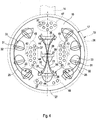
- An unspecified perforation of the first partition wall 17 is designed so that it 17 at least two exhaust gas partial streams 20, 21 generates in a flow through the first partition wall, the in Fig. 4 are indicated by arrows.
- these partial exhaust streams 20, 21 are generated so that they form in the injection chamber 16, two separate and opposite flow vortices 22 and 23, respectively.
- the two partial exhaust gas streams 20, 21 flow separately from one another in a region 25 extending proximally to a channel wall 24, while they largely flow together in a region 26 extending distally to the channel wall 24.
- the channel wall 24 bounds the injection chamber 16 laterally, extending in the circumferential direction and thereby forms the channel 13.
- the two flow vortices 22, 23 thereby rotate about separate vortex axes 42, 43, which run parallel to each other.
- the perforation of the first partition wall 17 is symmetrical with respect to a longitudinal center plane 27 of the channel 13, in particular mirror-symmetrically configured.
- the longitudinal center plane 27 includes a longitudinal central axis 28 of the channel 13, which coincides within the catalyst assembly 1 with the longitudinal central axis 7 of the housing 2. Due to the symmetry of the perforation of the first partition wall 17, the two flow vortices 22, 23 are formed symmetrically to the longitudinal central plane 27.
- the vertebral axes 42, 43 extend parallel to the longitudinal center axis 28 of the channel 13.
- the first partition 17 is preferably arranged in the channel 13 so that the injector 14 is in the longitudinal center plane 27, ie in the plane of symmetry of the first partition 17. to Illustration is in Fig.
- an in Fig. 3 indicated main injection direction 29 of an injection jet 30 of the injector 15 in the longitudinal center plane 27.
- the injection jet 30 is designed here cone-shaped, so that it can also be spoken of an injection cone. It is clear that for the injection jet 30 also any other geometries can be realized.
- the symmetrical first partition wall 17 is positioned in the channel 13 such that the two partial exhaust gas streams 20, 21 flow away from the injector port 14 proximal to the channel wall 24, ie in the proximal regions 25, while they flow together to the injector port 14 in distal regions 26.
- the perforation of the first partition wall 17 for generating the flow vortices 22, 23 has first openings 31 which are arranged proximal to the channel wall 24 and in the injection chamber 16, ie on a downstream side of the first partition 17 each have an exit surface facing away from the injector 14 32 own.
- the outlet surfaces 32 are formed by integrally formed on the first partition wall 17 wall portions 33 projecting from the remaining first partition 17 into the injection chamber 16.
- these first openings 31 each have an inlet surface 34 facing the injector port 14 at an inflow side of the first dividing wall 17 facing away from the injection chamber 16.
- wall sections 35 which are also integrally formed on the first dividing wall 17 and which are formed on the first partition wall 17 Upstream of the remaining first partition 17 protrude.
- the perforation of the first partition wall 17 also has further or second openings 36, the inlet surfaces also facing the injector connection 14 and the injector connection 14 facing away exit surfaces have.
- the entry surfaces are located on the side facing away from the injection chamber 16 side, while the exit surfaces are disposed within the injection chamber 16.
- the first openings 31 extend distributed in the circumferential direction proximal to the channel wall 13
- the second openings 36 are arranged distally to the channel wall 24 in a straight line one behind the other, preferably in the longitudinal center plane 27.
- the perforation of the first partition wall 17 may also have other or third openings 37 which are parallel to the longitudinal central axis 28 of the channel 13 can flow through and thereby generate 16 partial axial flows in the injection chamber. All third openings 37 are in the plane of the first partition wall 17th
- third openings 37 are arranged distally to the channel wall 24 between the first openings 31 and the second openings 36. Furthermore, these third openings 37 are arranged in two separate areas, namely in a first area 45 and in a second area 46. Extending through the first area 45 is a swirl axis 42 of the first flow vortex 22 around which the first flow vortex rotates. Through the second region 46, a second vortex axis 43 of the second flow vortex 23, around which the second flow vortex 23 rotates, extends. Further third openings 37 are located in a region 47 proximal to the injector port 14, and further third openings are located in a region 48 distal to the injector port 14.
- the third openings 37 of the proximal region 47 support the separation of the two exhaust gas partial flows, in each case surrounding a flow region 25 of the respective one Flow vortex 22, 23 to form.
- the third openings 37 of the distal region 48 prevent a reunification of the two wall-near flow regions 25 flowing toward one another and thereby support the formation of the wall-distant or central return flow regions 26 of the flow vortices 22, 23.
- the third openings 37 of the central regions 45 and 46 separate the wall-near flow regions 25 from the wall-distant flow regions 26 and thereby stabilize the two flow vortices 22, 23.
- the unspecified perforation of the second partition wall 18 may include first and second openings 38 and 39, each shielded with baffles 40.
- the guide surfaces 40 in each case project into the injection chamber 16.
- the first openings 38 are arranged proximal to the channel wall 24. They are elongated and extend substantially in the circumferential direction. They are shielded by the fins 40 inwards.
- the second openings 40 are arranged distally to the channel wall 24 and shielded by means of the guide surfaces 40 on a side facing the injector port 14 side.
- the second openings 39 are also elongate, but rectilinear and parallel to each other.
- the rectilinear, elongated second openings 39 extend transversely to the longitudinal center plane 27.
- the second partition 18 is also designed mirror-symmetrically to the longitudinal center plane 27; However, it differs from the first partition 17.
- the only optionally provided third partition wall 19 contains only one type of openings 41, each lying in the plane of the third partition wall 19 and define a uniform perforation in the example shown.
- the third partition 19 is expediently a simple perforated plate.
- the third partition wall 19 is thus configured in particular different from the first partition wall 17 and the second partition wall 18. Again, conceivable to provide a non-uniform perforation, so a perforation, the different openings with and / or without covers and / or vanes.
- the three partitions 17, 18, 19 are each basically configured, wherein in the first partition wall 17 and the second partition wall 18 integral portions of the respective partition wall 17, 18 can be transformed and exhibited to form the individual openings or the Strömungsleitkonturen ,
- the first partition wall 17 extends substantially perpendicular to the longitudinal central axis 28 of the channel 13.
- the third partition wall 19 expediently extends transversely to the longitudinal center axis 28 and thus parallel to the first partition 17.
- the second partition 18 extends inclined to the first partition wall 17th and thus also inclined to the third partition wall 19. The inclination of the first partition wall 17 to the second partition wall 18 is such that the injection chamber 17 tapers with increasing distance from the injector port 14.
Landscapes
- Chemical & Material Sciences (AREA)
- Engineering & Computer Science (AREA)
- Chemical Kinetics & Catalysis (AREA)
- Combustion & Propulsion (AREA)
- Mechanical Engineering (AREA)
- General Engineering & Computer Science (AREA)
- Health & Medical Sciences (AREA)
- Toxicology (AREA)
- Dispersion Chemistry (AREA)
- Exhaust Gas After Treatment (AREA)
Claims (14)
- Section d'injection d'un système de gaz d'échappement pour un moteur à combustion interne,- avec un canal (13) pour guider un flux de gaz d'échappement (3),- avec un raccord d'injecteur (14) qui est agencé latéralement sur le canal (13) et auquel peut être raccordé un injecteur (15) pour introduire un liquide ou un gaz dans le flux de gaz d'échappement (3),- avec une chambre d'injection (16) qui est conçue dans le canal (13) dans la zone du raccord d'injecteur (14) et qui est délimitée d'une part par une première paroi séparatrice (17) qui est agencée dans le canal (13) en amont du raccord d'injecteur (14) par rapport au flux de gaz d'échappement (3), qui est perforée et qui peut être traversée par le flux de gaz d'échappement (3) et d'autre part par une deuxième paroi séparatrice (18) qui est agencée dans le canal (13) en aval du raccord d'injecteur (14) par rapport au flux de gaz d'échappement (3), qui est perforée et qui peut être traversée par le flux de gaz d'échappement (3),- dans laquelle une perforation de la première paroi séparatrice (17) est conçue de telle sorte qu'elle produit, lors d'une traversée de la première paroi séparatrice (17), à l'intérieur de la chambre d'injection (16), au moins deux flux partiels de gaz d'échappement (20, 21) qui créent deux tourbillons de sens contraire (22, 23),- dans laquelle les deux flux partiels de gaz d'échappement (20, 21) s'écoulent séparément dans la zone proximale par rapport à une paroi de canal (24) délimitant latéralement la chambre d'injection (16) et ensemble dans la zone distale par rapport à la paroi de canal (24),- dans laquelle, pour produire les tourbillons (22, 23), la perforation de la première paroi séparatrice (17) comporte des premières ouvertures (31) qui sont agencées dans la zone proximale par rapport à la paroi de canal (24) et qui ont dans la chambre d'injection (16) chacune une surface de sortie (32) tournée à l'opposé du raccord d'injecteur (14),- dans laquelle les surfaces de sortie (32) sont formées au moyen de sections de paroi intégrales (33) de la première paroi séparatrice (17) qui font saillie de la première paroi séparatrice restante (17) dans la chambre d'injection (16),- dans laquelle les premières ouvertures (31) comportent chacune une surface d'entrée (34) tournée vers le raccord d'injecteur (14) sur un côté amont de la première paroi séparatrice (17) opposé à la chambre d'injection (16),- dans laquelle les surfaces d'entrée (34) sont formées au moyen de sections de paroi intégrales (35) de la première paroi séparatrice (17) qui sont éloignées de la première paroi séparatrice restante (17) sur le côté amont,- dans laquelle la première paroi séparatrice (17) est un corps de tôle plat à partir duquel les sections de paroi intégrales sont exposées pour former les premières ouvertures (31).
- Section d'injection selon la revendication 1, caractérisée en ce que la perforation de la première paroi séparatrice (17) est conçue symétrique par rapport à un plan médian longitudinal (27) du canal (13) de telle sorte que, lors d'une traversée de la première paroi séparatrice (17), les deux tourbillons (22, 23) se créent symétriquement par rapport au plan médian longitudinal (27).
- Section d'injection selon la revendication 2, caractérisée en ce que le raccord d'injecteur (14) est agencé dans ce plan médian longitudinal (27).
- Section d'injection selon l'une des revendications 1 à 3, caractérisée en ce que les deux flux partiels de gaz d'échappement (20, 21) s'écoulent, dans la zone proximale par rapport à la paroi de canal (24), chacun de manière à s'éloigner du raccord d'injecteur (14) et, dans la zone distale par rapport à la paroi de canal (24), ensemble de manière à se rapprocher du raccord d'injecteur (14).
- Section d'injection selon l'une quelconque des revendications 1 à 4, caractérisée en ce que, pour produire les tourbillons (22, 23), la perforation de la première paroi séparatrice (17) comporte en outre des deuxièmes ouvertures (36) qui sont agencées dans la zone distale par rapport à la paroi de canal (24) et qui ont dans la chambre d'injection (16) chacune une surface de d'entrée (44) tournée en direction du raccord d'injecteur (14).
- Section d'injection selon l'une quelconque des revendications 1 à 5, caractérisée en ce que, pour produire les tourbillons (22, 23), la perforation de la première paroi séparatrice (17) comporte en outre des troisièmes ouvertures (37) qui peuvent être traversées parallèlement à un axe médian longitudinal (28) du canal (13).
- Section d'injection selon les revendications 5 et 6, caractérisée en ce qu'au moins quelques-unes des troisièmes ouvertures (37) sont agencées entre les premières ouvertures (31) et les deuxièmes ouvertures (36).
- Section d'injection selon la revendication 6 ou 7, caractérisée en ce que les troisièmes ouvertures (37) se trouvent dans le plan de la première paroi séparatrice (17).
- Section d'injection selon l'une des revendications 6 à 8, caractérisée en ce que- quelques-unes des troisièmes ouvertures ou toutes les troisièmes ouvertures (37) sont agencées dans deux zones séparées (45, 46) à travers lesquelles s'étend respectivement un axe de tourbillon (42, 43) autour duquel tourne le tourbillon (22, 23) respectif,
et/ou- quelques-unes des troisièmes ouvertures (37) sont agencées dans une zone proximale (47) par rapport au raccord d'injecteur (14) et/ou dans une zone distale (48) par rapport au raccord d'injecteur (14). - Section d'injection selon l'une des revendications 1 à 9, caractérisée en ce qu'une perforation de la deuxième paroi séparatrice (18) comporte des ouvertures (38, 39) qui sont protégées avec des surfaces de guidage (40) qui dépassent dans la chambre d'injection (16).
- Section d'injection selon la revendication 10, caractérisée en ce que- les ouvertures de la perforation de la deuxième paroi séparatrice (18) comportent des premières ouvertures (38) qui sont agencées dans la zone proximale par rapport à la paroi de canal (24), qui sont allongées, qui s'étendent globalement dans la direction circonférentielle et qui sont protégées de façon radiale vers l'intérieur par la surface de guidage (40) respective,
et/ou- les ouvertures de la perforation de la deuxième paroi séparatrice (18) comportent des deuxièmes ouvertures (39) qui sont agencées dans la zone distale par rapport à la paroi de canal (24) et qui sont protégées par rapport au raccord d'injecteur (14) avec la surface de guidage (40) respective. - Section d'injection selon l'une des revendications 1 à 11, caractérisée en ce que la deuxième paroi séparatrice (18) est inclinée par rapport à la première paroi séparatrice (17) de telle sorte que la chambre d'injection (16) se rétrécit lorsque la distance au raccord d'injecteur (14) augmente.
- Section d'injection selon l'une des revendications 1 à 12, caractérisée en ce qu'il est prévu une troisième paroi séparatrice (19) perforée qui peut être traversée par le flux de gaz d'échappement (3) et qui est agencée en aval de la deuxième paroi séparatrice (18) par rapport au flux de gaz d'échappement (3).
- Dispositif catalytique pour un système de gaz d'échappement d'un moteur à combustion interne- avec un carter tubulaire (2) qui est destiné à guider un flux de gaz d'échappement (3) et qui contient un catalyseur à réduction catalytique sélective RCS (11) dans une section de sortie (5),- avec une section d'injection (12) selon l'une des revendications 1 à 13 qui est agencée en amont du catalyseur RCS (11) par rapport au flux de gaz d'échappement (3).
Applications Claiming Priority (2)
| Application Number | Priority Date | Filing Date | Title |
|---|---|---|---|
| DE102013221428.6A DE102013221428C5 (de) | 2013-10-22 | 2013-10-22 | Katalysatoranordnung mit Injektionsabschnitt |
| DE201310223033 DE102013223033A1 (de) | 2013-11-12 | 2013-11-12 | Katalysatoranordnung mit Injektionsabschnitt |
Publications (3)
| Publication Number | Publication Date |
|---|---|
| EP2865861A1 EP2865861A1 (fr) | 2015-04-29 |
| EP2865861B1 EP2865861B1 (fr) | 2016-04-27 |
| EP2865861B2 true EP2865861B2 (fr) | 2019-05-15 |
Family
ID=51176905
Family Applications (1)
| Application Number | Title | Priority Date | Filing Date |
|---|---|---|---|
| EP14174380.7A Active EP2865861B2 (fr) | 2013-10-22 | 2014-06-26 | Système de catalyseur avec section d'injection |
Country Status (3)
| Country | Link |
|---|---|
| US (1) | US9938878B2 (fr) |
| EP (1) | EP2865861B2 (fr) |
| WO (1) | WO2015059145A1 (fr) |
Families Citing this family (58)
| Publication number | Priority date | Publication date | Assignee | Title |
|---|---|---|---|---|
| DE202013006962U1 (de) | 2013-08-05 | 2013-08-28 | Tenneco Gmbh | Mischkammer |
| DE102014222698B4 (de) | 2014-11-06 | 2017-12-14 | Eberspächer Exhaust Technology GmbH & Co. KG | Abgasnachbehandlungseinrichtung mit Injektionsabschnitt |
| US9784163B2 (en) | 2015-01-22 | 2017-10-10 | Tenneco Automotive Operating Company Inc. | Exhaust aftertreatment system having mixer assembly |
| DE102015103425B3 (de) | 2015-03-09 | 2016-05-19 | Tenneco Gmbh | Mischvorrichtung |
| DE102015104540B3 (de) * | 2015-03-25 | 2016-02-04 | Tenneco Gmbh | Mischvorrichtung |
| BR112017023024B1 (pt) * | 2015-04-30 | 2024-01-23 | Faurecia Emissions Control Technologies, Usa, Llc | Misturador para um sistema de exaustão veicular |
| US9534525B2 (en) | 2015-05-27 | 2017-01-03 | Tenneco Automotive Operating Company Inc. | Mixer assembly for exhaust aftertreatment system |
| BR112017026777B1 (pt) | 2015-06-12 | 2022-11-16 | Donaldson Company, Inc | Dispositivo de tratamento de escape |
| FR3041691B1 (fr) * | 2015-09-29 | 2017-12-01 | Faurecia Systemes D'echappement | Ligne d'echappement avec injecteur de reactif |
| DE102016104361A1 (de) | 2016-03-10 | 2017-09-14 | Eberspächer Exhaust Technology GmbH & Co. KG | Mischer |
| CA3019194A1 (fr) | 2016-03-30 | 2017-10-05 | Marine Canada Acquisition Inc. | Appareil de chauffage de vehicule et commandes associees |
| JP6680624B2 (ja) * | 2016-06-07 | 2020-04-15 | 日野自動車株式会社 | 排気浄化装置 |
| FR3059710B1 (fr) * | 2016-12-05 | 2020-10-30 | Aaqius & Aaqius Sa | Dispositif et procede d'injection d'un gaz a melanger dans une ligne d'echappement |
| DE102016014966B4 (de) * | 2016-12-15 | 2023-04-20 | Daimler Truck AG | Abgasnachbehandlungseinrichtung für einen Kraftwagen |
| WO2018149509A1 (fr) | 2017-02-20 | 2018-08-23 | Volvo Penta Corporation | Boîte de mélange, son utilisation et procédé de mélange |
| US11085346B2 (en) * | 2017-05-31 | 2021-08-10 | Faurecia Emissions Control Technologies, Usa, Llc | Mixer for a vehicle exhaust system |
| US11136910B2 (en) * | 2017-06-06 | 2021-10-05 | Cummins Emission Solutions Inc. | Systems and methods for mixing exhaust gases and reductant in an aftertreatment system |
| CN109236429B (zh) * | 2017-07-11 | 2024-07-19 | 天纳克(苏州)排放系统有限公司 | 尾气后处理混合装置及其封装 |
| DE102017007662A1 (de) * | 2017-08-14 | 2019-02-14 | Ruscheweyh Consult Gmbh | Abgasanlage für einen Verbrennungsmotor, Flanschblech oder Lagerhülse, Abgaskrümmer, Fahrzeug sowie Verfahren zum Betrieb einer Abgasanlage |
| WO2019055922A1 (fr) | 2017-09-15 | 2019-03-21 | Eberspaecher North America, Inc. | Appareil de post-traitement des gaz d'échappement |
| CN109915236B (zh) * | 2017-12-13 | 2024-10-22 | 天纳克(苏州)排放系统有限公司 | 尾气后处理混合装置 |
| CN107939490A (zh) * | 2017-12-23 | 2018-04-20 | 无锡威孚力达催化净化器有限责任公司 | 轴进喷嘴集成式scr后处理双旋流尿素混合装置 |
| DE102018101253A1 (de) * | 2018-01-22 | 2019-07-25 | Eberspächer Exhaust Technology GmbH & Co. KG | Mischer |
| EP3517203A1 (fr) * | 2018-01-26 | 2019-07-31 | Donaldson Company, Inc. | Dispositif de mélange destiné à mélanger une pulvérisation d'un injecteur dans un gaz et système comprenant un tel dispositif |
| KR101999739B1 (ko) * | 2018-02-26 | 2019-10-01 | 세종공업 주식회사 | 믹서 내장형 우레아 믹싱장치 |
| DE102018204703A1 (de) * | 2018-03-28 | 2019-10-02 | Robert Bosch Gmbh | Vorrichtung zum Bereitstellen eines Ammoniak-aufweisenden Abgasnachbehandlungsmittels, Abgasnachbehandlungseinrichtung, Abgasnachbehandlungssystem und Verfahren |
| DE102019103780B4 (de) * | 2019-02-14 | 2024-01-25 | Friedrich Boysen Gmbh & Co. Kg | Mischer |
| FR3093346B1 (fr) * | 2019-02-28 | 2021-07-09 | Faurecia Systemes Dechappement | Dispositif d’injection et de mélange d’un gaz et ligne d’échappement comportant un tel dispositif |
| DE102019109983A1 (de) * | 2019-04-16 | 2020-10-22 | Eberspächer Exhaust Technology GmbH & Co. KG | Mischer |
| US10767537B1 (en) * | 2019-06-28 | 2020-09-08 | GM Global Technology Operations LLC | Hydrocarbon injector deflector assembly for diesel exhaust system |
| EP3997314B1 (fr) * | 2019-07-11 | 2024-03-06 | Donaldson Company, Inc. | Arrangement d'un conduit de dosage pour un système de post-traitement des gaz d'échappement |
| DE102019211883A1 (de) * | 2019-08-08 | 2021-02-11 | Robert Bosch Gmbh | Abgasnachbehandlungssystem für eine Brennkraftmaschine eines Kraftfahrzeugs |
| EP3792462A1 (fr) | 2019-09-13 | 2021-03-17 | Donaldson Company, Inc. | Ensembles de dosage et de mélange pour système de post-traitement d'échappement |
| EP4069954A4 (fr) | 2019-12-03 | 2023-08-09 | Cummins Emission Solutions Inc. | Système de distribution de réducteur pour système de post-traitement de gaz d'échappement |
| DE102020101134A1 (de) * | 2020-01-20 | 2021-07-22 | Eberspächer Exhaust Technology GmbH | Gas/Gas-Mischer zum Einleiten von Gas in den Abgasstrom einer Brennkraftmaschine |
| WO2021173357A1 (fr) | 2020-02-27 | 2021-09-02 | Cummins Emission Solutions Inc. | Mélangeurs destinés à être utilisés dans des systèmes de post-traitement |
| GB2609163B (en) | 2020-05-08 | 2023-08-23 | Cummins Emission Solutions Inc | Configurable aftertreatment systems including a housing |
| FR3110466A1 (fr) * | 2020-05-19 | 2021-11-26 | Faurecia Systemes D'echappement | Mélangeur de réducteur pour gaz d’échappement |
| WO2022074789A1 (fr) * | 2020-10-08 | 2022-04-14 | 昭和産業株式会社 | Farine de blé pour aliments frits |
| US12173632B2 (en) | 2020-10-22 | 2024-12-24 | Cummins Emission Solutions Inc. | Exhaust gas aftertreatment system |
| CN112539102A (zh) * | 2020-12-01 | 2021-03-23 | 保定市屹马汽车配件制造有限公司 | 一种汽车排气系统氨气混合器 |
| CN112459875B (zh) * | 2020-12-09 | 2024-06-25 | 无锡亿利环保科技有限公司 | 后处理尿素混合装置 |
| US12352196B2 (en) | 2021-02-02 | 2025-07-08 | Cummins Emission Solutions Inc. | Exhaust gas aftertreatment system |
| WO2022178231A1 (fr) | 2021-02-19 | 2022-08-25 | Purem Novi, Inc. | Appareil de post-traitement de gaz d'échappement |
| DE102021105724A1 (de) * | 2021-03-10 | 2022-09-15 | Purem GmbH | Abgas/Reaktionsmittel-Mischanordnung |
| US12123337B2 (en) | 2021-03-18 | 2024-10-22 | Cummins Emission Solutions Inc. | Aftertreatment systems |
| US11965449B2 (en) * | 2021-04-28 | 2024-04-23 | Cummins Emission Solutions Inc. | Venturi mixer with clamshell stamping |
| CN117396668A (zh) | 2021-07-27 | 2024-01-12 | 康明斯排放处理公司 | 废气后处理系统 |
| CN119643152A (zh) | 2021-08-23 | 2025-03-18 | 康明斯排放处理公司 | 用于后处理系统的出口取样系统 |
| US11549422B1 (en) | 2021-12-06 | 2023-01-10 | Tenneco Automotive Operating Company Inc. | Exhaust system for a combustion engine including a flow distributor |
| USD1042545S1 (en) | 2022-04-21 | 2024-09-17 | Cummins Emission Solutions Inc. | Aftertreatment system |
| USD1042544S1 (en) | 2022-04-21 | 2024-09-17 | Cummins Emission Solutions Inc. | Aftertreatment system |
| JP2024010905A (ja) * | 2022-07-13 | 2024-01-25 | ヤンマーホールディングス株式会社 | 排気ガス整流装置および排気ガス浄化システム |
| WO2024112898A1 (fr) | 2022-11-22 | 2024-05-30 | Purem Novi, Inc. | Amplificateur thermique pour appareil de traitement postcombustion des gaz d'échappement |
| CN116291814B (zh) * | 2023-04-17 | 2026-02-24 | 潍柴动力股份有限公司 | 一种尾气后处理装置 |
| CN116906156A (zh) * | 2023-08-08 | 2023-10-20 | 中船动力研究院有限公司 | 一种尿素和废气交叉流动混合反应装置 |
| KR102917843B1 (ko) * | 2023-12-21 | 2026-01-27 | 에스제이지중앙연구소 주식회사 | 요소수 혼합장치 |
| JP2025171357A (ja) * | 2024-05-09 | 2025-11-20 | いすゞ自動車株式会社 | 排気処理装置 |
Citations (6)
| Publication number | Priority date | Publication date | Assignee | Title |
|---|---|---|---|---|
| DE102006059761A1 (de) † | 2006-12-18 | 2008-06-19 | Arvinmeritor Emissions Technologies Gmbh | Abgasrohr für eine Abgasanlage einer Verbrennungskraftmaschine |
| DE102007005285A1 (de) † | 2007-02-02 | 2008-08-07 | H.C. Starck Gmbh | Verfahren zur Herstellung von Ammoniumheptamolybdat |
| DE202007010324U1 (de) † | 2007-07-25 | 2008-11-27 | Heinrich Gillet Gmbh | Vorrichtung zum Nachbehandeln der Abgase von Dieselmotoren |
| JP2009216074A (ja) † | 2008-03-10 | 2009-09-24 | Sango Co Ltd | 排気ガス浄化装置及びディーゼルエンジン用排気管 |
| DE102008053669A1 (de) † | 2008-10-29 | 2010-05-06 | Emcon Technologies Germany (Augsburg) Gmbh | Abgasanlage für ein Fahrzeug |
| WO2011087527A1 (fr) † | 2010-01-12 | 2011-07-21 | Donaldson Company, Inc. | Dispositif d'écoulement pour système de traitement de gaz d'échappement |
Family Cites Families (10)
| Publication number | Priority date | Publication date | Assignee | Title |
|---|---|---|---|---|
| GB2381218B (en) | 2001-10-25 | 2004-12-15 | Eminox Ltd | Gas treatment apparatus |
| JP2007032472A (ja) | 2005-07-28 | 2007-02-08 | Hitachi Ltd | 尿素水を用いた排気処理装置 |
| US7908845B2 (en) | 2007-04-16 | 2011-03-22 | GM Global Technology Operations LLC | Mixing apparatus for an exhaust after-treatment system |
| FR2947003B1 (fr) | 2009-06-19 | 2015-04-10 | Faurecia Sys Echappement | Ligne d'echappement avec systeme d'injection |
| DE102009036511B4 (de) * | 2009-08-07 | 2023-11-09 | Friedrich Boysen Gmbh & Co. Kg | Abgasanlage |
| WO2011073717A1 (fr) | 2009-12-18 | 2011-06-23 | Renault Trucks | Système de mélange pour un dispositif de post-traitement des gaz d'échappement |
| KR101251518B1 (ko) * | 2010-12-09 | 2013-04-05 | 기아자동차주식회사 | 차량의 배기가스 후처리 시스템용 도징 모듈 |
| EP2652279B1 (fr) * | 2010-12-15 | 2015-05-13 | Faurecia Systèmes d'Echappement | Ligne d'échappement avec dispositif d'injection de réactif gazeux |
| DE102010056314A1 (de) | 2010-12-27 | 2012-06-28 | Friedrich Boysen Gmbh & Co. Kg | Vorrichtung zum Verteilen von Fluiden in Abgasanlagen |
| FR3010137B1 (fr) | 2013-08-30 | 2016-08-26 | Faurecia Systemes D'echappement | Dispositif de purification de gaz d'echappement de moteur a combustion interne |
-
2014
- 2014-06-26 EP EP14174380.7A patent/EP2865861B2/fr active Active
- 2014-10-21 WO PCT/EP2014/072554 patent/WO2015059145A1/fr not_active Ceased
- 2014-10-21 US US14/519,624 patent/US9938878B2/en active Active
Patent Citations (6)
| Publication number | Priority date | Publication date | Assignee | Title |
|---|---|---|---|---|
| DE102006059761A1 (de) † | 2006-12-18 | 2008-06-19 | Arvinmeritor Emissions Technologies Gmbh | Abgasrohr für eine Abgasanlage einer Verbrennungskraftmaschine |
| DE102007005285A1 (de) † | 2007-02-02 | 2008-08-07 | H.C. Starck Gmbh | Verfahren zur Herstellung von Ammoniumheptamolybdat |
| DE202007010324U1 (de) † | 2007-07-25 | 2008-11-27 | Heinrich Gillet Gmbh | Vorrichtung zum Nachbehandeln der Abgase von Dieselmotoren |
| JP2009216074A (ja) † | 2008-03-10 | 2009-09-24 | Sango Co Ltd | 排気ガス浄化装置及びディーゼルエンジン用排気管 |
| DE102008053669A1 (de) † | 2008-10-29 | 2010-05-06 | Emcon Technologies Germany (Augsburg) Gmbh | Abgasanlage für ein Fahrzeug |
| WO2011087527A1 (fr) † | 2010-01-12 | 2011-07-21 | Donaldson Company, Inc. | Dispositif d'écoulement pour système de traitement de gaz d'échappement |
Also Published As
| Publication number | Publication date |
|---|---|
| US20150110681A1 (en) | 2015-04-23 |
| EP2865861A1 (fr) | 2015-04-29 |
| EP2865861B1 (fr) | 2016-04-27 |
| US9938878B2 (en) | 2018-04-10 |
| WO2015059145A1 (fr) | 2015-04-30 |
Similar Documents
| Publication | Publication Date | Title |
|---|---|---|
| EP2865861B2 (fr) | Système de catalyseur avec section d'injection | |
| DE102014222698B4 (de) | Abgasnachbehandlungseinrichtung mit Injektionsabschnitt | |
| EP2006017B1 (fr) | Dispositif de mélange et/ou d'évaporation et procédé de fabrication correspondant | |
| EP1985356B1 (fr) | Dispositif de mélange et/ou d'évaporation | |
| EP2813679B1 (fr) | Système d'échappement d'un moteur à combustion interne | |
| EP2022956B1 (fr) | Système d'échappement avec dispositif de guidage de l'écoulement | |
| EP2921220B1 (fr) | Mélangeur pour une installation de gaz d'échappement | |
| DE102020124106A1 (de) | Kraftfahrzeugabgasnachbehandlungssystem | |
| DE102008053168B4 (de) | Einrichtung zum Einbringen einer Flüssigkeit in eine Gasströmung | |
| DE102013221428B4 (de) | Katalysatoranordnung mit Injektionsabschnitt | |
| EP3443209B1 (fr) | Dispositif de post-traitement des gaz d'échappement doté d'un catalyseur et d'un dispositif de mélange | |
| DE102008017395B4 (de) | Misch- und/oder Verdampfungseinrichtung und zugehöriges Herstellungsverfahren | |
| EP2974787A2 (fr) | Melangeur statique | |
| DE102013223033A1 (de) | Katalysatoranordnung mit Injektionsabschnitt | |
| DE102013211662A1 (de) | Mischereinrichtung | |
| DE102017101749A1 (de) | Mischerelement zum Einmischen eines Fluids in ein Abgas eines Verbrennungsmotors sowie Abgasstrang für einen Verbrennungsmotor | |
| DE102012014528A1 (de) | Mehrstufiger Plattenmischer | |
| DE102011120221A1 (de) | Mischer für eine Abgasanlage und Abgasanlage | |
| DE102016014966A1 (de) | Abgasnachbehandlungseinrichtung für einen Kraftwagen | |
| EP4080025B1 (fr) | Agencement de mélange de gaz d'échappement / de charge | |
| DE102011085941B4 (de) | Misch- und/oder Verdampfungseinrichtung | |
| DE102018202298A1 (de) | Abgasnachbehandlungseinrichtung zum Eindosieren eines flüssigen Abgasnachbehandlungsmittels | |
| EP4453393B1 (fr) | Mélangeur pour un système de post-traitement des gaz d'échappement d'un véhicule automobile | |
| EP2823878A1 (fr) | Mélangeur à plaques à plusieurs étages |
Legal Events
| Date | Code | Title | Description |
|---|---|---|---|
| PUAI | Public reference made under article 153(3) epc to a published international application that has entered the european phase |
Free format text: ORIGINAL CODE: 0009012 |
|
| 17P | Request for examination filed |
Effective date: 20140626 |
|
| AK | Designated contracting states |
Kind code of ref document: A1 Designated state(s): AL AT BE BG CH CY CZ DE DK EE ES FI FR GB GR HR HU IE IS IT LI LT LU LV MC MK MT NL NO PL PT RO RS SE SI SK SM TR |
|
| AX | Request for extension of the european patent |
Extension state: BA ME |
|
| R17P | Request for examination filed (corrected) |
Effective date: 20150721 |
|
| RBV | Designated contracting states (corrected) |
Designated state(s): AL AT BE BG CH CY CZ DE DK EE ES FI FR GB GR HR HU IE IS IT LI LT LU LV MC MK MT NL NO PL PT RO RS SE SI SK SM TR |
|
| GRAP | Despatch of communication of intention to grant a patent |
Free format text: ORIGINAL CODE: EPIDOSNIGR1 |
|
| INTG | Intention to grant announced |
Effective date: 20151204 |
|
| GRAS | Grant fee paid |
Free format text: ORIGINAL CODE: EPIDOSNIGR3 |
|
| GRAA | (expected) grant |
Free format text: ORIGINAL CODE: 0009210 |
|
| AK | Designated contracting states |
Kind code of ref document: B1 Designated state(s): AL AT BE BG CH CY CZ DE DK EE ES FI FR GB GR HR HU IE IS IT LI LT LU LV MC MK MT NL NO PL PT RO RS SE SI SK SM TR |
|
| REG | Reference to a national code |
Ref country code: GB Ref legal event code: FG4D Free format text: NOT ENGLISH |
|
| REG | Reference to a national code |
Ref country code: CH Ref legal event code: EP |
|
| REG | Reference to a national code |
Ref country code: AT Ref legal event code: REF Ref document number: 795071 Country of ref document: AT Kind code of ref document: T Effective date: 20160515 |
|
| REG | Reference to a national code |
Ref country code: IE Ref legal event code: FG4D Free format text: LANGUAGE OF EP DOCUMENT: GERMAN |
|
| REG | Reference to a national code |
Ref country code: DE Ref legal event code: R096 Ref document number: 502014000690 Country of ref document: DE |
|
| REG | Reference to a national code |
Ref country code: FR Ref legal event code: PLFP Year of fee payment: 3 |
|
| REG | Reference to a national code |
Ref country code: SE Ref legal event code: TRGR |
|
| REG | Reference to a national code |
Ref country code: LT Ref legal event code: MG4D |
|
| REG | Reference to a national code |
Ref country code: NL Ref legal event code: MP Effective date: 20160427 |
|
| PG25 | Lapsed in a contracting state [announced via postgrant information from national office to epo] |
Ref country code: NL Free format text: LAPSE BECAUSE OF FAILURE TO SUBMIT A TRANSLATION OF THE DESCRIPTION OR TO PAY THE FEE WITHIN THE PRESCRIBED TIME-LIMIT Effective date: 20160427 |
|
| PG25 | Lapsed in a contracting state [announced via postgrant information from national office to epo] |
Ref country code: NO Free format text: LAPSE BECAUSE OF FAILURE TO SUBMIT A TRANSLATION OF THE DESCRIPTION OR TO PAY THE FEE WITHIN THE PRESCRIBED TIME-LIMIT Effective date: 20160727 Ref country code: FI Free format text: LAPSE BECAUSE OF FAILURE TO SUBMIT A TRANSLATION OF THE DESCRIPTION OR TO PAY THE FEE WITHIN THE PRESCRIBED TIME-LIMIT Effective date: 20160427 Ref country code: LT Free format text: LAPSE BECAUSE OF FAILURE TO SUBMIT A TRANSLATION OF THE DESCRIPTION OR TO PAY THE FEE WITHIN THE PRESCRIBED TIME-LIMIT Effective date: 20160427 Ref country code: PL Free format text: LAPSE BECAUSE OF FAILURE TO SUBMIT A TRANSLATION OF THE DESCRIPTION OR TO PAY THE FEE WITHIN THE PRESCRIBED TIME-LIMIT Effective date: 20160427 |
|
| PG25 | Lapsed in a contracting state [announced via postgrant information from national office to epo] |
Ref country code: ES Free format text: LAPSE BECAUSE OF FAILURE TO SUBMIT A TRANSLATION OF THE DESCRIPTION OR TO PAY THE FEE WITHIN THE PRESCRIBED TIME-LIMIT Effective date: 20160427 Ref country code: RS Free format text: LAPSE BECAUSE OF FAILURE TO SUBMIT A TRANSLATION OF THE DESCRIPTION OR TO PAY THE FEE WITHIN THE PRESCRIBED TIME-LIMIT Effective date: 20160427 Ref country code: HR Free format text: LAPSE BECAUSE OF FAILURE TO SUBMIT A TRANSLATION OF THE DESCRIPTION OR TO PAY THE FEE WITHIN THE PRESCRIBED TIME-LIMIT Effective date: 20160427 Ref country code: GR Free format text: LAPSE BECAUSE OF FAILURE TO SUBMIT A TRANSLATION OF THE DESCRIPTION OR TO PAY THE FEE WITHIN THE PRESCRIBED TIME-LIMIT Effective date: 20160728 Ref country code: LV Free format text: LAPSE BECAUSE OF FAILURE TO SUBMIT A TRANSLATION OF THE DESCRIPTION OR TO PAY THE FEE WITHIN THE PRESCRIBED TIME-LIMIT Effective date: 20160427 Ref country code: PT Free format text: LAPSE BECAUSE OF FAILURE TO SUBMIT A TRANSLATION OF THE DESCRIPTION OR TO PAY THE FEE WITHIN THE PRESCRIBED TIME-LIMIT Effective date: 20160829 |
|
| PG25 | Lapsed in a contracting state [announced via postgrant information from national office to epo] |
Ref country code: BE Free format text: LAPSE BECAUSE OF NON-PAYMENT OF DUE FEES Effective date: 20160630 |
|
| REG | Reference to a national code |
Ref country code: DE Ref legal event code: R026 Ref document number: 502014000690 Country of ref document: DE |
|
| PLBI | Opposition filed |
Free format text: ORIGINAL CODE: 0009260 |
|
| PG25 | Lapsed in a contracting state [announced via postgrant information from national office to epo] |
Ref country code: MC Free format text: LAPSE BECAUSE OF FAILURE TO SUBMIT A TRANSLATION OF THE DESCRIPTION OR TO PAY THE FEE WITHIN THE PRESCRIBED TIME-LIMIT Effective date: 20160427 Ref country code: EE Free format text: LAPSE BECAUSE OF FAILURE TO SUBMIT A TRANSLATION OF THE DESCRIPTION OR TO PAY THE FEE WITHIN THE PRESCRIBED TIME-LIMIT Effective date: 20160427 Ref country code: DK Free format text: LAPSE BECAUSE OF FAILURE TO SUBMIT A TRANSLATION OF THE DESCRIPTION OR TO PAY THE FEE WITHIN THE PRESCRIBED TIME-LIMIT Effective date: 20160427 Ref country code: CZ Free format text: LAPSE BECAUSE OF FAILURE TO SUBMIT A TRANSLATION OF THE DESCRIPTION OR TO PAY THE FEE WITHIN THE PRESCRIBED TIME-LIMIT Effective date: 20160427 Ref country code: SK Free format text: LAPSE BECAUSE OF FAILURE TO SUBMIT A TRANSLATION OF THE DESCRIPTION OR TO PAY THE FEE WITHIN THE PRESCRIBED TIME-LIMIT Effective date: 20160427 Ref country code: RO Free format text: LAPSE BECAUSE OF FAILURE TO SUBMIT A TRANSLATION OF THE DESCRIPTION OR TO PAY THE FEE WITHIN THE PRESCRIBED TIME-LIMIT Effective date: 20160427 |
|
| PLBI | Opposition filed |
Free format text: ORIGINAL CODE: 0009260 |
|
| PG25 | Lapsed in a contracting state [announced via postgrant information from national office to epo] |
Ref country code: SM Free format text: LAPSE BECAUSE OF FAILURE TO SUBMIT A TRANSLATION OF THE DESCRIPTION OR TO PAY THE FEE WITHIN THE PRESCRIBED TIME-LIMIT Effective date: 20160427 |
|
| 26 | Opposition filed |
Opponent name: TENNECO GMBH Effective date: 20170126 |
|
| PLAX | Notice of opposition and request to file observation + time limit sent |
Free format text: ORIGINAL CODE: EPIDOSNOBS2 |
|
| 26 | Opposition filed |
Opponent name: FAURECIA EMISSIONS CONTROL TECHNOLOGIES, GERMANY G Effective date: 20170127 |
|
| REG | Reference to a national code |
Ref country code: IE Ref legal event code: MM4A |
|
| PG25 | Lapsed in a contracting state [announced via postgrant information from national office to epo] |
Ref country code: IE Free format text: LAPSE BECAUSE OF NON-PAYMENT OF DUE FEES Effective date: 20160626 Ref country code: SI Free format text: LAPSE BECAUSE OF FAILURE TO SUBMIT A TRANSLATION OF THE DESCRIPTION OR TO PAY THE FEE WITHIN THE PRESCRIBED TIME-LIMIT Effective date: 20160427 |
|
| REG | Reference to a national code |
Ref country code: FR Ref legal event code: PLFP Year of fee payment: 4 |
|
| PLBB | Reply of patent proprietor to notice(s) of opposition received |
Free format text: ORIGINAL CODE: EPIDOSNOBS3 |
|
| REG | Reference to a national code |
Ref country code: CH Ref legal event code: PL |
|
| PG25 | Lapsed in a contracting state [announced via postgrant information from national office to epo] |
Ref country code: LI Free format text: LAPSE BECAUSE OF NON-PAYMENT OF DUE FEES Effective date: 20170630 Ref country code: CH Free format text: LAPSE BECAUSE OF NON-PAYMENT OF DUE FEES Effective date: 20170630 |
|
| PG25 | Lapsed in a contracting state [announced via postgrant information from national office to epo] |
Ref country code: HU Free format text: LAPSE BECAUSE OF FAILURE TO SUBMIT A TRANSLATION OF THE DESCRIPTION OR TO PAY THE FEE WITHIN THE PRESCRIBED TIME-LIMIT; INVALID AB INITIO Effective date: 20140626 |
|
| REG | Reference to a national code |
Ref country code: FR Ref legal event code: PLFP Year of fee payment: 5 |
|
| PG25 | Lapsed in a contracting state [announced via postgrant information from national office to epo] |
Ref country code: LU Free format text: LAPSE BECAUSE OF NON-PAYMENT OF DUE FEES Effective date: 20160626 Ref country code: IS Free format text: LAPSE BECAUSE OF FAILURE TO SUBMIT A TRANSLATION OF THE DESCRIPTION OR TO PAY THE FEE WITHIN THE PRESCRIBED TIME-LIMIT Effective date: 20160427 Ref country code: CY Free format text: LAPSE BECAUSE OF FAILURE TO SUBMIT A TRANSLATION OF THE DESCRIPTION OR TO PAY THE FEE WITHIN THE PRESCRIBED TIME-LIMIT Effective date: 20160427 Ref country code: MK Free format text: LAPSE BECAUSE OF FAILURE TO SUBMIT A TRANSLATION OF THE DESCRIPTION OR TO PAY THE FEE WITHIN THE PRESCRIBED TIME-LIMIT Effective date: 20160427 Ref country code: MT Free format text: LAPSE BECAUSE OF FAILURE TO SUBMIT A TRANSLATION OF THE DESCRIPTION OR TO PAY THE FEE WITHIN THE PRESCRIBED TIME-LIMIT Effective date: 20160427 |
|
| PG25 | Lapsed in a contracting state [announced via postgrant information from national office to epo] |
Ref country code: BG Free format text: LAPSE BECAUSE OF FAILURE TO SUBMIT A TRANSLATION OF THE DESCRIPTION OR TO PAY THE FEE WITHIN THE PRESCRIBED TIME-LIMIT Effective date: 20160427 |
|
| PG25 | Lapsed in a contracting state [announced via postgrant information from national office to epo] |
Ref country code: TR Free format text: LAPSE BECAUSE OF FAILURE TO SUBMIT A TRANSLATION OF THE DESCRIPTION OR TO PAY THE FEE WITHIN THE PRESCRIBED TIME-LIMIT Effective date: 20160427 Ref country code: AL Free format text: LAPSE BECAUSE OF FAILURE TO SUBMIT A TRANSLATION OF THE DESCRIPTION OR TO PAY THE FEE WITHIN THE PRESCRIBED TIME-LIMIT Effective date: 20160427 |
|
| PGFP | Annual fee paid to national office [announced via postgrant information from national office to epo] |
Ref country code: IT Payment date: 20180622 Year of fee payment: 5 |
|
| PUAH | Patent maintained in amended form |
Free format text: ORIGINAL CODE: 0009272 |
|
| STAA | Information on the status of an ep patent application or granted ep patent |
Free format text: STATUS: PATENT MAINTAINED AS AMENDED |
|
| 27A | Patent maintained in amended form |
Effective date: 20190515 |
|
| AK | Designated contracting states |
Kind code of ref document: B2 Designated state(s): AL AT BE BG CH CY CZ DE DK EE ES FI FR GB GR HR HU IE IS IT LI LT LU LV MC MK MT NL NO PL PT RO RS SE SI SK SM TR |
|
| REG | Reference to a national code |
Ref country code: DE Ref legal event code: R102 Ref document number: 502014000690 Country of ref document: DE |
|
| REG | Reference to a national code |
Ref country code: SE Ref legal event code: RPEO |
|
| PG25 | Lapsed in a contracting state [announced via postgrant information from national office to epo] |
Ref country code: IT Free format text: LAPSE BECAUSE OF NON-PAYMENT OF DUE FEES Effective date: 20190626 |
|
| REG | Reference to a national code |
Ref country code: AT Ref legal event code: MM01 Ref document number: 795071 Country of ref document: AT Kind code of ref document: T Effective date: 20190626 |
|
| PG25 | Lapsed in a contracting state [announced via postgrant information from national office to epo] |
Ref country code: AT Free format text: LAPSE BECAUSE OF NON-PAYMENT OF DUE FEES Effective date: 20190626 |
|
| REG | Reference to a national code |
Ref country code: DE Ref legal event code: R081 Ref document number: 502014000690 Country of ref document: DE Owner name: PUREM GMBH, DE Free format text: FORMER OWNER: EBERSPAECHER EXHAUST TECHNOLOGY GMBH & CO. KG, 66539 NEUNKIRCHEN, DE |
|
| PGFP | Annual fee paid to national office [announced via postgrant information from national office to epo] |
Ref country code: DE Payment date: 20250618 Year of fee payment: 12 |
|
| PGFP | Annual fee paid to national office [announced via postgrant information from national office to epo] |
Ref country code: GB Payment date: 20250620 Year of fee payment: 12 |
|
| PGFP | Annual fee paid to national office [announced via postgrant information from national office to epo] |
Ref country code: FR Payment date: 20250626 Year of fee payment: 12 |
|
| PGFP | Annual fee paid to national office [announced via postgrant information from national office to epo] |
Ref country code: SE Payment date: 20250618 Year of fee payment: 12 |