EP2865879A1 - Schaufelverbindungsabschnittstruktur und strahltriebwerk damit - Google Patents
Schaufelverbindungsabschnittstruktur und strahltriebwerk damit Download PDFInfo
- Publication number
- EP2865879A1 EP2865879A1 EP20130806092 EP13806092A EP2865879A1 EP 2865879 A1 EP2865879 A1 EP 2865879A1 EP 20130806092 EP20130806092 EP 20130806092 EP 13806092 A EP13806092 A EP 13806092A EP 2865879 A1 EP2865879 A1 EP 2865879A1
- Authority
- EP
- European Patent Office
- Prior art keywords
- vane
- end portion
- joint surface
- pair
- divided pieces
- Prior art date
- Legal status (The legal status is an assumption and is not a legal conclusion. Google has not performed a legal analysis and makes no representation as to the accuracy of the status listed.)
- Granted
Links
Images


Classifications
-
- F—MECHANICAL ENGINEERING; LIGHTING; HEATING; WEAPONS; BLASTING
- F02—COMBUSTION ENGINES; HOT-GAS OR COMBUSTION-PRODUCT ENGINE PLANTS
- F02K—JET-PROPULSION PLANTS
- F02K3/00—Plants including a gas turbine driving a compressor or a ducted fan
- F02K3/02—Plants including a gas turbine driving a compressor or a ducted fan in which part of the working fluid by-passes the turbine and combustion chamber
- F02K3/04—Plants including a gas turbine driving a compressor or a ducted fan in which part of the working fluid by-passes the turbine and combustion chamber the plant including ducted fans, i.e. fans with high volume, low pressure outputs, for augmenting the jet thrust, e.g. of double-flow type
- F02K3/06—Plants including a gas turbine driving a compressor or a ducted fan in which part of the working fluid by-passes the turbine and combustion chamber the plant including ducted fans, i.e. fans with high volume, low pressure outputs, for augmenting the jet thrust, e.g. of double-flow type with front fan
-
- F—MECHANICAL ENGINEERING; LIGHTING; HEATING; WEAPONS; BLASTING
- F01—MACHINES OR ENGINES IN GENERAL; ENGINE PLANTS IN GENERAL; STEAM ENGINES
- F01D—NON-POSITIVE DISPLACEMENT MACHINES OR ENGINES, e.g. STEAM TURBINES
- F01D25/00—Component parts, details, or accessories, not provided for in, or of interest apart from, other groups
- F01D25/005—Selecting particular materials
-
- F—MECHANICAL ENGINEERING; LIGHTING; HEATING; WEAPONS; BLASTING
- F01—MACHINES OR ENGINES IN GENERAL; ENGINE PLANTS IN GENERAL; STEAM ENGINES
- F01D—NON-POSITIVE DISPLACEMENT MACHINES OR ENGINES, e.g. STEAM TURBINES
- F01D25/00—Component parts, details, or accessories, not provided for in, or of interest apart from, other groups
- F01D25/24—Casings; Casing parts, e.g. diaphragms, casing fastenings
-
- F—MECHANICAL ENGINEERING; LIGHTING; HEATING; WEAPONS; BLASTING
- F01—MACHINES OR ENGINES IN GENERAL; ENGINE PLANTS IN GENERAL; STEAM ENGINES
- F01D—NON-POSITIVE DISPLACEMENT MACHINES OR ENGINES, e.g. STEAM TURBINES
- F01D5/00—Blades; Blade-carrying members; Heating, heat-insulating, cooling or antivibration means on the blades or the members
- F01D5/12—Blades
- F01D5/28—Selecting particular materials; Particular measures relating thereto; Measures against erosion or corrosion
- F01D5/282—Selecting composite materials, e.g. blades with reinforcing filaments
-
- F—MECHANICAL ENGINEERING; LIGHTING; HEATING; WEAPONS; BLASTING
- F01—MACHINES OR ENGINES IN GENERAL; ENGINE PLANTS IN GENERAL; STEAM ENGINES
- F01D—NON-POSITIVE DISPLACEMENT MACHINES OR ENGINES, e.g. STEAM TURBINES
- F01D9/00—Stators
- F01D9/02—Nozzles; Nozzle boxes; Stator blades; Guide conduits, e.g. individual nozzles
-
- F—MECHANICAL ENGINEERING; LIGHTING; HEATING; WEAPONS; BLASTING
- F02—COMBUSTION ENGINES; HOT-GAS OR COMBUSTION-PRODUCT ENGINE PLANTS
- F02C—GAS-TURBINE PLANTS; AIR INTAKES FOR JET-PROPULSION PLANTS; CONTROLLING FUEL SUPPLY IN AIR-BREATHING JET-PROPULSION PLANTS
- F02C7/00—Features, components parts, details or accessories, not provided for in, or of interest apart form groups F02C1/00 - F02C6/00; Air intakes for jet-propulsion plants
- F02C7/20—Mounting or supporting of plant; Accommodating heat expansion or creep
-
- F—MECHANICAL ENGINEERING; LIGHTING; HEATING; WEAPONS; BLASTING
- F05—INDEXING SCHEMES RELATING TO ENGINES OR PUMPS IN VARIOUS SUBCLASSES OF CLASSES F01-F04
- F05D—INDEXING SCHEME FOR ASPECTS RELATING TO NON-POSITIVE-DISPLACEMENT MACHINES OR ENGINES, GAS-TURBINES OR JET-PROPULSION PLANTS
- F05D2230/00—Manufacture
- F05D2230/60—Assembly methods
- F05D2230/64—Assembly methods using positioning or alignment devices for aligning or centring, e.g. pins
- F05D2230/644—Assembly methods using positioning or alignment devices for aligning or centring, e.g. pins for adjusting the position or the alignment, e.g. wedges or eccenters
-
- F—MECHANICAL ENGINEERING; LIGHTING; HEATING; WEAPONS; BLASTING
- F05—INDEXING SCHEMES RELATING TO ENGINES OR PUMPS IN VARIOUS SUBCLASSES OF CLASSES F01-F04
- F05D—INDEXING SCHEME FOR ASPECTS RELATING TO NON-POSITIVE-DISPLACEMENT MACHINES OR ENGINES, GAS-TURBINES OR JET-PROPULSION PLANTS
- F05D2240/00—Components
- F05D2240/10—Stators
- F05D2240/12—Fluid guiding means, e.g. vanes
-
- F—MECHANICAL ENGINEERING; LIGHTING; HEATING; WEAPONS; BLASTING
- F05—INDEXING SCHEMES RELATING TO ENGINES OR PUMPS IN VARIOUS SUBCLASSES OF CLASSES F01-F04
- F05D—INDEXING SCHEME FOR ASPECTS RELATING TO NON-POSITIVE-DISPLACEMENT MACHINES OR ENGINES, GAS-TURBINES OR JET-PROPULSION PLANTS
- F05D2260/00—Function
- F05D2260/30—Retaining components in desired mutual position
- F05D2260/31—Retaining bolts or nuts
-
- F—MECHANICAL ENGINEERING; LIGHTING; HEATING; WEAPONS; BLASTING
- F05—INDEXING SCHEMES RELATING TO ENGINES OR PUMPS IN VARIOUS SUBCLASSES OF CLASSES F01-F04
- F05D—INDEXING SCHEME FOR ASPECTS RELATING TO NON-POSITIVE-DISPLACEMENT MACHINES OR ENGINES, GAS-TURBINES OR JET-PROPULSION PLANTS
- F05D2300/00—Materials; Properties thereof
- F05D2300/40—Organic materials
- F05D2300/44—Resins
-
- F—MECHANICAL ENGINEERING; LIGHTING; HEATING; WEAPONS; BLASTING
- F05—INDEXING SCHEMES RELATING TO ENGINES OR PUMPS IN VARIOUS SUBCLASSES OF CLASSES F01-F04
- F05D—INDEXING SCHEME FOR ASPECTS RELATING TO NON-POSITIVE-DISPLACEMENT MACHINES OR ENGINES, GAS-TURBINES OR JET-PROPULSION PLANTS
- F05D2300/00—Materials; Properties thereof
- F05D2300/60—Properties or characteristics given to material by treatment or manufacturing
- F05D2300/603—Composites; e.g. fibre-reinforced
-
- Y—GENERAL TAGGING OF NEW TECHNOLOGICAL DEVELOPMENTS; GENERAL TAGGING OF CROSS-SECTIONAL TECHNOLOGIES SPANNING OVER SEVERAL SECTIONS OF THE IPC; TECHNICAL SUBJECTS COVERED BY FORMER USPC CROSS-REFERENCE ART COLLECTIONS [XRACs] AND DIGESTS
- Y02—TECHNOLOGIES OR APPLICATIONS FOR MITIGATION OR ADAPTATION AGAINST CLIMATE CHANGE
- Y02T—CLIMATE CHANGE MITIGATION TECHNOLOGIES RELATED TO TRANSPORTATION
- Y02T50/00—Aeronautics or air transport
- Y02T50/60—Efficient propulsion technologies, e.g. for aircraft
Definitions
- the present invention relates to, for example, a coupling part structure for a vane used for a coupling part to an engine main body, of guide vanes that are vanes constituting an aircraft jet engine, and a jet engine including the coupling part structure for the vane.
- Such a jet engine as described above is normally provided with: rotor blades for introducing air into an engine main body; and guide vanes that are stator vanes for controlling a flow of the air introduced by the rotor blades.
- the guide vanes may be required to have only the flow controlling function, and may be required to also have a structural function of coupling a fan frame and a fan case constituting the engine main body, in addition to the flow controlling function.
- a metal material such as an aluminum alloy or a composite material of thermosetting resin such as epoxy resin and reinforcement fiber such as carbon fiber is normally adopted as the constituent material of each guide vane, and a strut that is placed downstream of the guide vanes and is made of a metal material such as an aluminum alloy as its constituent material is provided with the structural function.
- a metal material such as an aluminum alloy is adopted as the constituent material of each guide vane.
- the weight of each guide vane itself can be reduced by an amount corresponding to using the composite material as its constituent material, whereas the reduction in weight of the aircraft jet engine is prevented by an amount corresponding to assigning the structural function to the strut that is made of the metal material such as the aluminum alloy as its constituent material.
- the metal material such as the aluminum alloy is used as the constituent material of each guide vane, and hence the reduction in weight of the aircraft jet engine is prevented, which is the same problem as that in the case of using the strut.
- This is a conventional problem to be solved.
- the present invention which has been made in view of the above-mentioned conventional problem, has an object to provide a coupling part structure for a vane capable of obtaining a high structural strength while contributing to a reduction in weight of a jet engine, and a jet engine including the coupling part structure for the vane.
- the present invention provides a coupling part structure for a vane that constitutes a jet engine and is made of a composite material of thermosetting resin or thermoplastic resin and reinforcement fiber, the coupling part structure comprising a vane coupling part, wherein the vane coupling part includes a coupling support member placed therein, the coupling support member being made of metal and including a pair of divided pieces separated from each other, the pair of divided pieces being joined to an end portion of the vane from both sides in a vane thickness direction, on an either one of respective end joint surfaces of the pair of divided pieces of the coupling support member, a linear protrusion is formed in an axis direction of the jet engine, and in the other end joint surface, a groove is formed in the axis direction of the jet engine to face the linear protrusion, the end portion of the vane is formed into a concavo-convex shape in a state with a constant vane thickness in a radial direction of the jet engine, the end portion of the vane
- an adhesive is interposed between the pair of divided pieces of the coupling support member and the end portion of the vane held between the pair of divided pieces.
- the vane is preferably a stator vane of the jet engine.
- the present invention further provides a jet engine including the above-mentioned coupling part structure for the vane as a coupling part structure for a vane constituting the jet engine.
- the coupling part structure for the vane according to the present invention can be applied to: a coupling part between a vane distal end portion of a guide vane that is a stator vane of a jet engine and an engine main body; and a coupling part between a vane proximal end portion of, similarly, the guide vane and the engine main body, and can also be applied to: a coupling part between a tip (distal end portion) of a rotor blade of the jet engine and a tip shroud; and a coupling part between a hub (proximal end portion) of, similarly, the rotor blade and a shaft.
- the tip shroud is provided to the tip of the rotor blade for the purpose of vibration prevention and aerodynamic performance improvement, and rotates together with the rotor blade.
- the linear protrusions or grooves formed on the end joint surface(s) of the coupling support member can be trapezoidal, semicircular, triangular, and rectangular in cross-section, but are not limited to these shapes.
- thermosetting resin usable to form the vane examples include epoxy resin, phenolic resin, and polyimide resin
- thermoplastic resin usable to form, similarly, the vane include polyetherimide, polyether ether ketone, and polyphenylene sulfide
- reinforcement fiber usable to form the vane examples include carbon fiber, aramid fiber, and glass fiber.
- the vane is formed by, for example, laminating the composite material of these substances in the vane thickness direction or three-dimensionally inweaving the composite material thereof. Meanwhile, metal such as an aluminum alloy and a titanium alloy can be used to form the coupling support member.
- the end portion of the vane made of the composite material is located between the pair of divided pieces of the coupling support member made of the metal. Further, the groove which is formed in either one joint surface to the coupling support member in the end portion of the vane is engaged with the linear protrusions which is formed on either one end joint surface of the coupling support member, and the linear protrusions which is formed on the other joint surface to the coupling support member in the end portion of the vane is engaged with the groove which is formed in the other end joint surface of the coupling support member.
- the fastening force obtained by the bolts and the nuts is applied to the pair of divided pieces of the coupling support member from both the sides in the vane thickness direction, whereby the end portion of the vane is held between the pair of divided pieces of the coupling support member.
- the coupling part structure for the vane according to the present invention is capable of obtaining a high structural strength while contributing to a reduction in weight of the jet engine.
- the coupling strength is a mechanical coupling strength, process management for the coupling part is facilitated compared with the coupling strength in the case of using only an adhesive, for example.
- the end portion of the vane is sandwiched between the pair of divided pieces from both the sides in the vane thickness direction, a turn of the end portion of the vane can be avoided compared with, for example, the case where the end portion of the vane is supported by only one of the divided pieces. As a result, a strong coupling state can be maintained.
- the groove and the linear protrusion in the end portion of the vane is engaged with the linear protrusion and the groove in the coupling support member, whereby the two components are positioned with each other. Accordingly, this assembling work is facilitated.
- the end portion of the vane is formed into a concavo-convex shape while the vane thickness is kept constant in the radial direction of the jet engine, that is, the groove and the linear protrusion on the vane end portion side are formed by continuous fiber, and therefore, strength can be kept or improved without increasing the number of process steps.
- the adhesive is interposed between the pair of divided pieces of the coupling support member and the end portion of the vane held between the pair of divided pieces, a higher structural strength can be obtained, and if the vane is a stator vane of the jet engine, for example, the guide vane, the flow controlling function as required is exhibited.
- a groove and a linear protrusion can be continuously formed on either one joint surface of the joint surfaces to the pair of divided pieces, and a linear protrusion and a groove can be continuously formed on the other joint surface of the joint surfaces to the pair of divided pieces and at respective back side positions of the groove and the linear protrusion in the either one joint surface.
- two grooves can be formed with a space therebetween, for example, in either one joint surface, while two linear protrusions can be formed on the other joint surface and at respective back side positions of the two grooves in the either one joint surface, and if these configurations are adopted, the structural strength is increased more correspondingly to an amount of increase of an adhesion area.
- the jet engine according to the present invention adopts the coupling part structure for the vane according to the present invention, to thereby achieve both a reduction in weight and an increase in strength.
- a coupling part structure for a vane according to the present invention produces an excellent effect of obtaining a high structural strength while contributing to a reduction in weight of a jet engine.
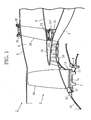
- FIG. 1 to FIG. 4 illustrate one embodiment of a coupling part structure for a vane according to the present invention, and a coupling part of each guide vane as a stator vane constituting a jet engine is described as an example in this embodiment.
- an annular core flow passage 4 is formed on a shaft core side of an engine inner cylinder 3 of an engine main body 2, and a bypass flow passage 6 is formed between the inner circumferential surface of a fan case 5 and the outer circumferential surface of the engine inner cylinder 3 corresponding to an outer portion of the engine main body 2.
- a fan disc 7 is rotatably set around the engine shaft core (not illustrated) with the intermediation of a bearing 8.
- the fan disc 7 is integrally coupled to a turbine rotor of a low-pressure turbine (not illustrated) placed in a back portion (on the right side of FIG. 1 ) of the jet engine 1.
- a plurality of rotor blades 10 are placed at regular intervals in the circumferential direction with the intermediation of fitting grooves 7a, and spacers 11, 11 are respectively placed in a front portion and a back portion between each rotor blade 10 and each fitting groove 7a.
- Annular retainers 12, 13 that support the rotor blades 10 are respectively integrally set in the circumferential direction in a front portion and a back portion of the fan disc 7.
- the retainer 12 in the front portion is integrally coupled to a nose cone 14, and the retainer 13 in the back portion is coaxially and integrally coupled to a rotor 16 of a low-pressure compressor 15 that is adjacently placed downstream of the fan disc 7.
- tip shrouds for vibration prevention and aerodynamic performance improvement are respectively coupled between the tips of the plurality of rotor blades 10, and the tip shrouds are not illustrated in FIG. 1 .
- the jet engine 1 includes a plurality of guide vanes (stator vanes) 20 on the bypass flow passage 6.
- the plurality of guide vanes 20 are placed at regular intervals around the engine inner cylinder 3, and regulate a swirling flow of air flowing in the bypass flow passage 6.
- a composite material of: thermosetting resin (such as epoxy resin, phenolic resin, and polyimide resin) or thermoplastic resin (such as polyetherimide, polyether ether ketone, and polyphenylene sulfide); and reinforcement fiber (such as carbon fiber, aramid fiber, and glass fiber) is used as the constituent material of each guide vane 20.
- the guide vane 20 is formed by, for example, laminating the constituent material in the vane thickness direction or three-dimensionally inweaving the constituent material.
- a vane proximal end portion (vane end portion) 21 on a shaft core side of each guide vane 20 is coupled to an attachment flange 31f of a fan frame 31 placed on the engine inner cylinder 3, and a vane distal end portion (vane end portion) 22 on a side farther from the shaft core of the guide vane 20 is coupled to an attachment flange 5f placed on the fan case 5.
- a coupling support member 33 including a pair of divided pieces 34, 34 separated from each other is placed in a coupling part between the vane proximal end portion 21 of the guide vane 20 and the attachment flange 31f, namely, a vane coupling part, and the pair of divided pieces 34, 34 are joined to the vane proximal end portion 21 of the guide vane 20 from both the sides in the vane thickness direction (the left-right direction in FIG. 2 ).
- Each of the divided pieces 34, 34 of the coupling support member 33 is made of metal such as an aluminum alloy and a titanium alloy, and is attached to the attachment flange 31f using a bolt 38 and a nut 39.
- Opposed walls 35 facing each other are respectively formed on the pair of divided pieces 34, 34 of the coupling support member 33, and the opposed walls 35, 35 are joined to the vane proximal end portion 21 of the guide vane 20 from both the sides in the vane thickness direction.
- a groove 35b having a section forming a trapezoidal shape is formed in an engine axis direction
- a linear protrusion 35c having a section forming a trapezoidal shape is formed to face the groove 35b.
- the vane proximal end portion 21 of the guide vane 20 is formed into a concavo-convex shape in a state with a constant vane thickness in a radial direction of the engine, and on a joint surface 21a at the left side of FIG. 2 of the joint surfaces 21a, 21a in the vane proximal end portion 21 of the guide vane 20, a linear protrusion 21b that mutually engages with the groove 35b which is formed in the end joint surface 35a in the divided piece 34 at the left side of FIG. 2 is formed, and a groove 21c that mutually engages with the linear protrusion 35c which is formed on the end joint surface 35a in the divided piece 34 at the right side of FIG. 2 is formed on the joint surface 21a at the right side of FIG. 2 of the joint surfaces 21a, 21a and at a back side position of the linear protrusion 21b in the joint surface 21a at the left side of FIG. 2 .
- the vane proximal end portion 21 of the guide vane 20 is held between the respective opposed walls 35, 35 of the pair of divided pieces 34, 34 by the fastening force that is applied by a bolt 36 and a nut 37 to the pair of divided pieces 34, 34 of the coupling support member 33 from both the sides in the vane thickness direction.
- an adhesive is interposed between the respective opposed walls 35, 35 of the pair of divided pieces 34, 34 of the coupling support member 33 and the vane proximal end portion 21 of the guide vane 20 held between the opposed walls 35, 35.
- a coupling support member 53 including a pair of divided pieces 54, 54 separated from each other is placed also in a coupling part between the vane distal end portion 22 of the guide vane 20 and the attachment flange 5f, namely, a vane coupling part, and the pair of divided pieces 54, 54 are joined to the vane distal end portion 22 of the guide vane 20 from both the sides in the vane thickness direction (the left-right direction in FIG. 2 ).
- Each of the divided pieces 54, 54 of the coupling support member 53 is made of metal such as an aluminum alloy and a titanium alloy, and is attached to the attachment flange 5f using the bolt 38 and the nut 39.
- Opposed walls 55, 55 facing each other are respectively formed also on the pair of divided pieces 54, 54 of the coupling support member 53, and the opposed walls 55, 55 are joined to the vane distal end portion 22 of the guide vane 20 from both the sides in the vane thickness direction.
- a groove 55b having a section forming a trapezoidal shape is formed in an engine axis direction
- a linear protrusion 55c having a section forming a trapezoidal shape is formed to face the groove 55b.
- the vane distal end portion 22 of the guide vane 20 is formed into a concavo-convex shape in a state with a constant vane thickness in the radial direction of the engine, and on a joint surface 22a at the left side of FIG. 2 of the joint surfaces 22a and 22a in the vane distal end portion 22 of the guide vane 20, a linear protrusion 22b that mutually engages with the groove 55b which is formed in the end portion joint surface 55a in the divided piece 54 at the left side of FIG. 2 is formed, and a groove 22c that mutually engages with the linear protrusion 55c which is formed on the end portion joint surface 55a in the divided piece 54 at the right side of FIG. 2 is formed on the joint surface 22a at the right side of FIG. 2 of the joint surfaces 22a, 22a, and at a back side position of the linear protrusion 22b in the joint surface 22a at the left side of FIG. 2 .
- the vane distal end portion 22 of the guide vane 20 is held between the respective opposed walls 55, 55 of the pair of divided pieces 54, 54 by the fastening force that is applied by a bolt 56 and a nut 57 to the pair of divided pieces 54, 54 of the coupling support member 53 from both the sides in the vane thickness direction.
- an adhesive is interposed between the respective opposed walls 55, 55 of the pair of divided pieces 54, 54 of the coupling support member 53 and the vane distal end portion 22 of the guide vane 20 held between the opposed walls 55, 55.
- each guide vane 20 made of the composite material is located between the respective opposed walls 35, 35 of the pair of divided pieces 34, 34 of the coupling support member 33 made of the metal.
- the linear protrusion 21b formed on the joint surface 21a on the left side of FIG. 2 of the vane proximal end portion 21 is engaged with the groove 35b formed on the joint surface 35a on the left side of FIG. 2 of the coupling support member 33
- the groove 21c formed on the joint surface 21a on the right side of FIG. 2 of the vane proximal end portion 21 is engaged with the linear protrusion 35c formed on the joint surface 35a on the right side of FIG. 2 of the coupling support member 33.
- each guide vane 20 is located between the respective opposed walls 55, 55 of the pair of divided pieces 54, 54 of the coupling support member 53 made of the metal.
- the linear protrusion 22b formed on the joint surface 22a on the left side of FIG. 2 of the vane distal end portion 22 is engaged with the groove 55b formed on the joint surface 55a on the left side of FIG. 2 of the coupling support member 53
- the groove 22c formed on the joint surface 22a on the right side of FIG. 2 of the vane distal end portion 22 is engaged with the linear protrusion 55c formed on the joint surface 55a on the right side of FIG. 2 of the coupling support member 53.
- the coupling part structure for the vane according to this embodiment is capable of obtaining a high structural strength while contributing to a reduction in weight of the jet engine 1.
- the coupling strength is a mechanical coupling strength, process management for the coupling part is facilitated compared with the coupling strength in the case of using only an adhesive, for example.
- vane proximal end portion 21 (vane distal end portion 22) is sandwiched between the respective opposed walls 35, 35 (55, 55) of the pair of divided pieces 34, 34 (54, 54) from both the sides in the vane thickness direction, a turn of the vane proximal end portion 21 (the vane distal end portion 22) can be avoided compared with, for example, the case where the vane proximal end portion 21 (the vane distal end portion 22) is supported by a wall on one side. As a result, a strong coupling state can be maintained.
- the groove 21c (22c) and the linear protrusion 21b (22b) of the vane proximal end portion 21 (the vane distal end portion 22) are respectively engaged with the linear protrusion 35c (55c) and the groove 35b (55b) of the coupling support member 33 (53), whereby the two components are positioned with each other. Accordingly, this assembling work is facilitated.
- the vane proximal end portion 21 (the vane distal end portion 22) is formed into a concavo-convex shape while keeping the vane thickness constant in the radial direction of the engine, that is, the groove 21c (22c) and the linear protrusion 21b (22b) on the vane proximal end portion 21 (the vane distal end portion 22) side are molded by continuous fiber, and therefore, strength can be kept or improved without increasing the number of process steps.
- the adhesive is interposed between the respective opposed walls 35, 35 (55, 55) of the pair of divided pieces 34, 34 (54, 54) of the coupling support member 33 (53) and the vane proximal end portion 21 (the vane distal end portion 22) of the guide vane 20 held between the opposed walls 35, 35 (55, 55), and hence a higher structural strength can be obtained.
- the vane is the guide vane 20 as a stator vane of the jet engine 1, and therefore, the original flow controlling function of the guide vane 20 is exhibited.
- the jet engine according to this embodiment adopts the above-mentioned coupling part structure for the vane, and thus achieves both a reduction in weight and an increase in strength.
- the coupling part structure for the vane according to the present invention is applied to the vane coupling part of each guide vane as the stator vane of the jet engine, but the present invention is not limited thereto.
- the coupling part structure for the vane according to the present invention can also be applied to a coupling part between: a tip (distal end portion) 62 of each rotor blade 60 of the jet engine; and a tip shroud 85 that is provided to the tip 62 for the purpose of vibration prevention and aerodynamic performance improvement and rotates together with the rotor blade 60.
- a groove 75b having a section forming a trapezoidal shape is formed, and on a joint surface 75a at the right side of FIG. 5 of the respective joint surfaces 75a, 75a, a linear protrusion 75c is formed to face the groove 75b.
- the tip 62 of the rotor blade 60 is formed into a concavo-convex shape, and on a joint surface 62a at the left side of FIG. 5 of the joint surfaces 62a, 62a in the tip 62 of the rotor blade 60, a linear protrusion 62b that engages with the groove 75b which is formed in the joint surface 75a in the divided piece 74 at the left side of FIG. 5 is formed, and a groove 62c that mutually engages with the linear protrusion 75c which is formed on the joint surface 75a in the divided piece 74 at the right side of FIG. 5 is formed, on the joint surface 62a at the right side of FIG. 5 of the joint surfaces 62a, 62a.
- the coupling part structure for the vane according to the above-mentioned embodiment is also capable of obtaining a higher structural strength while contributing to the reduction in weight of the jet engine.
- the linear protrusions 21b, 22b, 62b and the grooves 21c, 22c, 62c on the vane end portion side, and the grooves 35b, 55b, 75b and the linear protrusions 35c, 55c, 75c on the coupling support member side all form trapezoidal shapes in section
- the present invention is not limited thereto, and the linear protrusions and the grooves which have the sections forming semicircular shapes, forming triangular shapes, or forming rectangular shapes can be adopted, as the linear protrusions and the grooves.
Landscapes
- Engineering & Computer Science (AREA)
- Mechanical Engineering (AREA)
- General Engineering & Computer Science (AREA)
- Chemical & Material Sciences (AREA)
- Materials Engineering (AREA)
- Combustion & Propulsion (AREA)
- Composite Materials (AREA)
- Structures Of Non-Positive Displacement Pumps (AREA)
- Lining Or Joining Of Plastics Or The Like (AREA)
- Turbine Rotor Nozzle Sealing (AREA)
Applications Claiming Priority (2)
| Application Number | Priority Date | Filing Date | Title |
|---|---|---|---|
| JP2012138655A JP6082193B2 (ja) | 2012-06-20 | 2012-06-20 | 翼の連結部構造及びこれを用いたジェットエンジン |
| PCT/JP2013/066786 WO2013191195A1 (ja) | 2012-06-20 | 2013-06-19 | 翼の連結部構造及びこれを用いたジェットエンジン |
Publications (3)
| Publication Number | Publication Date |
|---|---|
| EP2865879A1 true EP2865879A1 (de) | 2015-04-29 |
| EP2865879A4 EP2865879A4 (de) | 2016-03-02 |
| EP2865879B1 EP2865879B1 (de) | 2018-10-31 |
Family
ID=49768789
Family Applications (1)
| Application Number | Title | Priority Date | Filing Date |
|---|---|---|---|
| EP13806092.6A Active EP2865879B1 (de) | 2012-06-20 | 2013-06-19 | Schaufelverbindungsabschnittstruktur und strahltriebwerk damit |
Country Status (7)
| Country | Link |
|---|---|
| US (1) | US9896963B2 (de) |
| EP (1) | EP2865879B1 (de) |
| JP (1) | JP6082193B2 (de) |
| CN (1) | CN104334863B (de) |
| CA (1) | CA2871842C (de) |
| RU (1) | RU2601696C2 (de) |
| WO (1) | WO2013191195A1 (de) |
Cited By (1)
| Publication number | Priority date | Publication date | Assignee | Title |
|---|---|---|---|---|
| FR3064671A1 (fr) * | 2017-03-29 | 2018-10-05 | Safran Aircraft Engines | Bras de liaison d'une turbomachine muni d'un element de retenue de cale |
Families Citing this family (3)
| Publication number | Priority date | Publication date | Assignee | Title |
|---|---|---|---|---|
| JP6612161B2 (ja) * | 2016-03-24 | 2019-11-27 | 川崎重工業株式会社 | タービンの支持構造 |
| US11065825B2 (en) * | 2018-12-05 | 2021-07-20 | Raytheon Technologies Corporation | High temperature composite seal |
| JP7120913B2 (ja) * | 2018-12-25 | 2022-08-17 | 三菱重工業株式会社 | ガスタービン排気車室及びガスタービン |
Family Cites Families (27)
| Publication number | Priority date | Publication date | Assignee | Title |
|---|---|---|---|---|
| JPH0444404U (de) * | 1990-08-14 | 1992-04-15 | ||
| JPH06105048B2 (ja) | 1991-05-28 | 1994-12-21 | ゼネラル・エレクトリック・カンパニイ | コアフレームを静翼フレームに安定中央リングで着脱自在に取付ける装置 |
| JP2766423B2 (ja) | 1991-05-28 | 1998-06-18 | ゼネラル・エレクトリック・カンパニイ | 取り外し可能なターボファン・エンジン組立体 |
| FR2685383B1 (fr) | 1991-12-18 | 1994-02-11 | Snecma | Bras structural du carter d'une turbomachine. |
| US5272869A (en) * | 1992-12-10 | 1993-12-28 | General Electric Company | Turbine frame |
| US5653580A (en) | 1995-03-06 | 1997-08-05 | Solar Turbines Incorporated | Nozzle and shroud assembly mounting structure |
| CA2231986A1 (en) * | 1997-01-10 | 1999-09-12 | Masahito Kataoka | Stationary blade of integrated segment construction and manufacturing method therefor |
| JP4040922B2 (ja) * | 2001-07-19 | 2008-01-30 | 株式会社東芝 | 組立式ノズルダイアフラムおよびその組立方法 |
| US6761807B2 (en) * | 2002-03-09 | 2004-07-13 | United Technologies Corporation | Molded tooling for use in airfoil stripping processes |
| US6908279B2 (en) * | 2003-11-25 | 2005-06-21 | General Electric Company | Method of installing stationary blades of a turbine and turbine structure having a radial loading pin |
| EP1548233B1 (de) * | 2003-12-18 | 2006-08-02 | Techspace Aero S.A. | Befestigungsvorrichtung für Statorschaufel, sowie Leitschaufelstufe eines Verdichters mit einer solchen Vorrichtung |
| RU40655U1 (ru) * | 2004-04-05 | 2004-09-20 | Открытое акционерное общество "Научно-производственное объединение "Сатурн" | Стоечный узел двигателя |
| SE528948C2 (sv) * | 2004-12-23 | 2007-03-20 | Volvo Aero Corp | Ringformad vridstyv statisk komponent för en flygplansmotor |
| GB0505978D0 (en) | 2005-03-24 | 2005-04-27 | Alstom Technology Ltd | Interlocking turbine blades |
| US8079773B2 (en) | 2005-10-18 | 2011-12-20 | General Electric Company | Methods and apparatus for assembling composite structures |
| SE0700823L (sv) * | 2007-03-30 | 2008-10-01 | Volvo Aero Corp | Komponent för en gasturbinmotor, jetmotor försedd med en sådan komponent, samt en flygmaskin försedd med en sådan jetmotor |
| US8061977B2 (en) * | 2007-07-03 | 2011-11-22 | Siemens Energy, Inc. | Ceramic matrix composite attachment apparatus and method |
| US7609465B2 (en) * | 2008-03-05 | 2009-10-27 | Tdk Taiwan Corporation | EMI-proof miniature lens focusing mechanism |
| EP2321499B1 (de) * | 2008-08-29 | 2017-12-13 | GKN Aerospace Sweden AB | Komponente und gasturbinenmotor mit der komponente |
| US8251651B2 (en) * | 2009-01-28 | 2012-08-28 | United Technologies Corporation | Segmented ceramic matrix composite turbine airfoil component |
| FR2941487B1 (fr) * | 2009-01-28 | 2011-03-04 | Snecma | Aube de turbomachine en materiau composite a pied renforce |
| US8070429B2 (en) * | 2009-03-11 | 2011-12-06 | General Electric Company | Turbine singlet nozzle assembly with mechanical and weld fabrication |
| US8226361B2 (en) * | 2009-07-08 | 2012-07-24 | General Electric Company | Composite article and support frame assembly |
| FR2958680B1 (fr) * | 2010-04-13 | 2015-08-14 | Snecma | Carter intermediaire de turboreacteur multi-flux |
| FR2961847B1 (fr) * | 2010-06-25 | 2012-08-17 | Snecma | Roue mobile a aubes en materiau composite pour moteur a turbine a gaz a liaison pied d'aube/disque par serrage |
| US8734101B2 (en) * | 2010-08-31 | 2014-05-27 | General Electric Co. | Composite vane mounting |
| FR3006368B1 (fr) * | 2013-05-28 | 2015-07-03 | Herakles | Aube de disque de rotor avec retenue du pied par frottement |
-
2012
- 2012-06-20 JP JP2012138655A patent/JP6082193B2/ja not_active Expired - Fee Related
-
2013
- 2013-06-19 WO PCT/JP2013/066786 patent/WO2013191195A1/ja not_active Ceased
- 2013-06-19 CA CA2871842A patent/CA2871842C/en active Active
- 2013-06-19 RU RU2015101531/06A patent/RU2601696C2/ru active
- 2013-06-19 CN CN201380023301.XA patent/CN104334863B/zh not_active Expired - Fee Related
- 2013-06-19 EP EP13806092.6A patent/EP2865879B1/de active Active
-
2014
- 2014-10-31 US US14/398,360 patent/US9896963B2/en active Active
Cited By (1)
| Publication number | Priority date | Publication date | Assignee | Title |
|---|---|---|---|---|
| FR3064671A1 (fr) * | 2017-03-29 | 2018-10-05 | Safran Aircraft Engines | Bras de liaison d'une turbomachine muni d'un element de retenue de cale |
Also Published As
| Publication number | Publication date |
|---|---|
| CA2871842C (en) | 2018-03-06 |
| US9896963B2 (en) | 2018-02-20 |
| JP6082193B2 (ja) | 2017-02-15 |
| CN104334863B (zh) | 2016-09-07 |
| EP2865879B1 (de) | 2018-10-31 |
| CN104334863A (zh) | 2015-02-04 |
| CA2871842A1 (en) | 2013-12-27 |
| EP2865879A4 (de) | 2016-03-02 |
| RU2015101531A (ru) | 2016-08-10 |
| RU2601696C2 (ru) | 2016-11-10 |
| JP2014001708A (ja) | 2014-01-09 |
| WO2013191195A1 (ja) | 2013-12-27 |
| US20150132118A1 (en) | 2015-05-14 |
Similar Documents
| Publication | Publication Date | Title |
|---|---|---|
| CA2863001C (en) | Coupling part structure for vane and jet engine including the same | |
| US8449260B2 (en) | Composite load-bearing rotating ring and process therefor | |
| CA2725238C (en) | Architecture of a compressor rectifier | |
| EP2713014A2 (de) | Ringförmiger Füller für Axialstrommaschine | |
| US10677090B2 (en) | Component having co-bonded composite and metal rings and method of assembling same | |
| JP2015528540A (ja) | ガスタービンエンジン用の低半径比のファン | |
| US10215040B2 (en) | Coupling part structure for vane and jet engine including the same | |
| US9896963B2 (en) | Coupling part structure for vane and jet engine including the same | |
| US10557350B2 (en) | I beam blade platform | |
| CN105229263A (zh) | 复合物压缩机叶片及组装的方法 |
Legal Events
| Date | Code | Title | Description |
|---|---|---|---|
| PUAI | Public reference made under article 153(3) epc to a published international application that has entered the european phase |
Free format text: ORIGINAL CODE: 0009012 |
|
| 17P | Request for examination filed |
Effective date: 20141112 |
|
| AK | Designated contracting states |
Kind code of ref document: A1 Designated state(s): AL AT BE BG CH CY CZ DE DK EE ES FI FR GB GR HR HU IE IS IT LI LT LU LV MC MK MT NL NO PL PT RO RS SE SI SK SM TR |
|
| AX | Request for extension of the european patent |
Extension state: BA ME |
|
| DAX | Request for extension of the european patent (deleted) | ||
| RA4 | Supplementary search report drawn up and despatched (corrected) |
Effective date: 20160203 |
|
| RIC1 | Information provided on ipc code assigned before grant |
Ipc: F01D 25/24 20060101ALI20160128BHEP Ipc: F01D 25/00 20060101ALI20160128BHEP Ipc: F01D 9/02 20060101ALI20160128BHEP Ipc: F02C 7/00 20060101ALI20160128BHEP Ipc: F02K 3/06 20060101AFI20160128BHEP Ipc: F01D 5/28 20060101ALI20160128BHEP |
|
| GRAP | Despatch of communication of intention to grant a patent |
Free format text: ORIGINAL CODE: EPIDOSNIGR1 |
|
| STAA | Information on the status of an ep patent application or granted ep patent |
Free format text: STATUS: GRANT OF PATENT IS INTENDED |
|
| RIC1 | Information provided on ipc code assigned before grant |
Ipc: F01D 25/24 20060101ALI20180426BHEP Ipc: F01D 9/02 20060101ALI20180426BHEP Ipc: F01D 5/28 20060101ALI20180426BHEP Ipc: F01D 25/00 20060101ALI20180426BHEP Ipc: F02C 7/00 20060101ALI20180426BHEP Ipc: F02K 3/06 20060101AFI20180426BHEP |
|
| INTG | Intention to grant announced |
Effective date: 20180529 |
|
| GRAS | Grant fee paid |
Free format text: ORIGINAL CODE: EPIDOSNIGR3 |
|
| GRAA | (expected) grant |
Free format text: ORIGINAL CODE: 0009210 |
|
| STAA | Information on the status of an ep patent application or granted ep patent |
Free format text: STATUS: THE PATENT HAS BEEN GRANTED |
|
| AK | Designated contracting states |
Kind code of ref document: B1 Designated state(s): AL AT BE BG CH CY CZ DE DK EE ES FI FR GB GR HR HU IE IS IT LI LT LU LV MC MK MT NL NO PL PT RO RS SE SI SK SM TR |
|
| REG | Reference to a national code |
Ref country code: CH Ref legal event code: EP Ref country code: GB Ref legal event code: FG4D |
|
| REG | Reference to a national code |
Ref country code: AT Ref legal event code: REF Ref document number: 1059711 Country of ref document: AT Kind code of ref document: T Effective date: 20181115 |
|
| REG | Reference to a national code |
Ref country code: DE Ref legal event code: R096 Ref document number: 602013046055 Country of ref document: DE |
|
| REG | Reference to a national code |
Ref country code: IE Ref legal event code: FG4D |
|
| REG | Reference to a national code |
Ref country code: NL Ref legal event code: MP Effective date: 20181031 |
|
| REG | Reference to a national code |
Ref country code: LT Ref legal event code: MG4D |
|
| REG | Reference to a national code |
Ref country code: AT Ref legal event code: MK05 Ref document number: 1059711 Country of ref document: AT Kind code of ref document: T Effective date: 20181031 |
|
| PG25 | Lapsed in a contracting state [announced via postgrant information from national office to epo] |
Ref country code: FI Free format text: LAPSE BECAUSE OF FAILURE TO SUBMIT A TRANSLATION OF THE DESCRIPTION OR TO PAY THE FEE WITHIN THE PRESCRIBED TIME-LIMIT Effective date: 20181031 Ref country code: AT Free format text: LAPSE BECAUSE OF FAILURE TO SUBMIT A TRANSLATION OF THE DESCRIPTION OR TO PAY THE FEE WITHIN THE PRESCRIBED TIME-LIMIT Effective date: 20181031 Ref country code: LV Free format text: LAPSE BECAUSE OF FAILURE TO SUBMIT A TRANSLATION OF THE DESCRIPTION OR TO PAY THE FEE WITHIN THE PRESCRIBED TIME-LIMIT Effective date: 20181031 Ref country code: IS Free format text: LAPSE BECAUSE OF FAILURE TO SUBMIT A TRANSLATION OF THE DESCRIPTION OR TO PAY THE FEE WITHIN THE PRESCRIBED TIME-LIMIT Effective date: 20190228 Ref country code: PL Free format text: LAPSE BECAUSE OF FAILURE TO SUBMIT A TRANSLATION OF THE DESCRIPTION OR TO PAY THE FEE WITHIN THE PRESCRIBED TIME-LIMIT Effective date: 20181031 Ref country code: HR Free format text: LAPSE BECAUSE OF FAILURE TO SUBMIT A TRANSLATION OF THE DESCRIPTION OR TO PAY THE FEE WITHIN THE PRESCRIBED TIME-LIMIT Effective date: 20181031 Ref country code: BG Free format text: LAPSE BECAUSE OF FAILURE TO SUBMIT A TRANSLATION OF THE DESCRIPTION OR TO PAY THE FEE WITHIN THE PRESCRIBED TIME-LIMIT Effective date: 20190131 Ref country code: NO Free format text: LAPSE BECAUSE OF FAILURE TO SUBMIT A TRANSLATION OF THE DESCRIPTION OR TO PAY THE FEE WITHIN THE PRESCRIBED TIME-LIMIT Effective date: 20190131 Ref country code: ES Free format text: LAPSE BECAUSE OF FAILURE TO SUBMIT A TRANSLATION OF THE DESCRIPTION OR TO PAY THE FEE WITHIN THE PRESCRIBED TIME-LIMIT Effective date: 20181031 Ref country code: LT Free format text: LAPSE BECAUSE OF FAILURE TO SUBMIT A TRANSLATION OF THE DESCRIPTION OR TO PAY THE FEE WITHIN THE PRESCRIBED TIME-LIMIT Effective date: 20181031 |
|
| PG25 | Lapsed in a contracting state [announced via postgrant information from national office to epo] |
Ref country code: AL Free format text: LAPSE BECAUSE OF FAILURE TO SUBMIT A TRANSLATION OF THE DESCRIPTION OR TO PAY THE FEE WITHIN THE PRESCRIBED TIME-LIMIT Effective date: 20181031 Ref country code: NL Free format text: LAPSE BECAUSE OF FAILURE TO SUBMIT A TRANSLATION OF THE DESCRIPTION OR TO PAY THE FEE WITHIN THE PRESCRIBED TIME-LIMIT Effective date: 20181031 Ref country code: PT Free format text: LAPSE BECAUSE OF FAILURE TO SUBMIT A TRANSLATION OF THE DESCRIPTION OR TO PAY THE FEE WITHIN THE PRESCRIBED TIME-LIMIT Effective date: 20190301 Ref country code: SE Free format text: LAPSE BECAUSE OF FAILURE TO SUBMIT A TRANSLATION OF THE DESCRIPTION OR TO PAY THE FEE WITHIN THE PRESCRIBED TIME-LIMIT Effective date: 20181031 Ref country code: RS Free format text: LAPSE BECAUSE OF FAILURE TO SUBMIT A TRANSLATION OF THE DESCRIPTION OR TO PAY THE FEE WITHIN THE PRESCRIBED TIME-LIMIT Effective date: 20181031 Ref country code: GR Free format text: LAPSE BECAUSE OF FAILURE TO SUBMIT A TRANSLATION OF THE DESCRIPTION OR TO PAY THE FEE WITHIN THE PRESCRIBED TIME-LIMIT Effective date: 20190201 |
|
| PG25 | Lapsed in a contracting state [announced via postgrant information from national office to epo] |
Ref country code: CZ Free format text: LAPSE BECAUSE OF FAILURE TO SUBMIT A TRANSLATION OF THE DESCRIPTION OR TO PAY THE FEE WITHIN THE PRESCRIBED TIME-LIMIT Effective date: 20181031 Ref country code: DK Free format text: LAPSE BECAUSE OF FAILURE TO SUBMIT A TRANSLATION OF THE DESCRIPTION OR TO PAY THE FEE WITHIN THE PRESCRIBED TIME-LIMIT Effective date: 20181031 |
|
| REG | Reference to a national code |
Ref country code: DE Ref legal event code: R097 Ref document number: 602013046055 Country of ref document: DE |
|
| PG25 | Lapsed in a contracting state [announced via postgrant information from national office to epo] |
Ref country code: SM Free format text: LAPSE BECAUSE OF FAILURE TO SUBMIT A TRANSLATION OF THE DESCRIPTION OR TO PAY THE FEE WITHIN THE PRESCRIBED TIME-LIMIT Effective date: 20181031 Ref country code: EE Free format text: LAPSE BECAUSE OF FAILURE TO SUBMIT A TRANSLATION OF THE DESCRIPTION OR TO PAY THE FEE WITHIN THE PRESCRIBED TIME-LIMIT Effective date: 20181031 Ref country code: SK Free format text: LAPSE BECAUSE OF FAILURE TO SUBMIT A TRANSLATION OF THE DESCRIPTION OR TO PAY THE FEE WITHIN THE PRESCRIBED TIME-LIMIT Effective date: 20181031 Ref country code: RO Free format text: LAPSE BECAUSE OF FAILURE TO SUBMIT A TRANSLATION OF THE DESCRIPTION OR TO PAY THE FEE WITHIN THE PRESCRIBED TIME-LIMIT Effective date: 20181031 |
|
| PLBE | No opposition filed within time limit |
Free format text: ORIGINAL CODE: 0009261 |
|
| STAA | Information on the status of an ep patent application or granted ep patent |
Free format text: STATUS: NO OPPOSITION FILED WITHIN TIME LIMIT |
|
| 26N | No opposition filed |
Effective date: 20190801 |
|
| PG25 | Lapsed in a contracting state [announced via postgrant information from national office to epo] |
Ref country code: SI Free format text: LAPSE BECAUSE OF FAILURE TO SUBMIT A TRANSLATION OF THE DESCRIPTION OR TO PAY THE FEE WITHIN THE PRESCRIBED TIME-LIMIT Effective date: 20181031 |
|
| PG25 | Lapsed in a contracting state [announced via postgrant information from national office to epo] |
Ref country code: MC Free format text: LAPSE BECAUSE OF FAILURE TO SUBMIT A TRANSLATION OF THE DESCRIPTION OR TO PAY THE FEE WITHIN THE PRESCRIBED TIME-LIMIT Effective date: 20181031 |
|
| REG | Reference to a national code |
Ref country code: CH Ref legal event code: PL |
|
| REG | Reference to a national code |
Ref country code: BE Ref legal event code: MM Effective date: 20190630 |
|
| PG25 | Lapsed in a contracting state [announced via postgrant information from national office to epo] |
Ref country code: TR Free format text: LAPSE BECAUSE OF FAILURE TO SUBMIT A TRANSLATION OF THE DESCRIPTION OR TO PAY THE FEE WITHIN THE PRESCRIBED TIME-LIMIT Effective date: 20181031 |
|
| PG25 | Lapsed in a contracting state [announced via postgrant information from national office to epo] |
Ref country code: IE Free format text: LAPSE BECAUSE OF NON-PAYMENT OF DUE FEES Effective date: 20190619 |
|
| PG25 | Lapsed in a contracting state [announced via postgrant information from national office to epo] |
Ref country code: LI Free format text: LAPSE BECAUSE OF NON-PAYMENT OF DUE FEES Effective date: 20190630 Ref country code: CH Free format text: LAPSE BECAUSE OF NON-PAYMENT OF DUE FEES Effective date: 20190630 Ref country code: BE Free format text: LAPSE BECAUSE OF NON-PAYMENT OF DUE FEES Effective date: 20190630 Ref country code: LU Free format text: LAPSE BECAUSE OF NON-PAYMENT OF DUE FEES Effective date: 20190619 |
|
| PG25 | Lapsed in a contracting state [announced via postgrant information from national office to epo] |
Ref country code: CY Free format text: LAPSE BECAUSE OF FAILURE TO SUBMIT A TRANSLATION OF THE DESCRIPTION OR TO PAY THE FEE WITHIN THE PRESCRIBED TIME-LIMIT Effective date: 20181031 |
|
| PG25 | Lapsed in a contracting state [announced via postgrant information from national office to epo] |
Ref country code: HU Free format text: LAPSE BECAUSE OF FAILURE TO SUBMIT A TRANSLATION OF THE DESCRIPTION OR TO PAY THE FEE WITHIN THE PRESCRIBED TIME-LIMIT; INVALID AB INITIO Effective date: 20130619 Ref country code: MT Free format text: LAPSE BECAUSE OF FAILURE TO SUBMIT A TRANSLATION OF THE DESCRIPTION OR TO PAY THE FEE WITHIN THE PRESCRIBED TIME-LIMIT Effective date: 20181031 |
|
| PG25 | Lapsed in a contracting state [announced via postgrant information from national office to epo] |
Ref country code: MK Free format text: LAPSE BECAUSE OF FAILURE TO SUBMIT A TRANSLATION OF THE DESCRIPTION OR TO PAY THE FEE WITHIN THE PRESCRIBED TIME-LIMIT Effective date: 20181031 |
|
| PGFP | Annual fee paid to national office [announced via postgrant information from national office to epo] |
Ref country code: IT Payment date: 20220510 Year of fee payment: 10 |
|
| REG | Reference to a national code |
Ref country code: DE Ref legal event code: R081 Ref document number: 602013046055 Country of ref document: DE Owner name: IHI CORP., JP Free format text: FORMER OWNERS: IHI AEROSPACE CO., LTD., TOKYO, JP; IHI CORP., TOKYO, JP |
|
| REG | Reference to a national code |
Ref country code: GB Ref legal event code: 732E Free format text: REGISTERED BETWEEN 20240411 AND 20240417 |
|
| PG25 | Lapsed in a contracting state [announced via postgrant information from national office to epo] |
Ref country code: IT Free format text: LAPSE BECAUSE OF NON-PAYMENT OF DUE FEES Effective date: 20230619 |
|
| PGFP | Annual fee paid to national office [announced via postgrant information from national office to epo] |
Ref country code: DE Payment date: 20250429 Year of fee payment: 13 |
|
| PGFP | Annual fee paid to national office [announced via postgrant information from national office to epo] |
Ref country code: GB Payment date: 20250501 Year of fee payment: 13 |
|
| PGFP | Annual fee paid to national office [announced via postgrant information from national office to epo] |
Ref country code: FR Payment date: 20250508 Year of fee payment: 13 |