EP2865976B1 - Reinigung von Kohlendioxid - Google Patents
Reinigung von Kohlendioxid Download PDFInfo
- Publication number
- EP2865976B1 EP2865976B1 EP14189928.6A EP14189928A EP2865976B1 EP 2865976 B1 EP2865976 B1 EP 2865976B1 EP 14189928 A EP14189928 A EP 14189928A EP 2865976 B1 EP2865976 B1 EP 2865976B1
- Authority
- EP
- European Patent Office
- Prior art keywords
- carbon dioxide
- column system
- impurity
- enriched
- heavy
- Prior art date
- Legal status (The legal status is an assumption and is not a legal conclusion. Google has not performed a legal analysis and makes no representation as to the accuracy of the status listed.)
- Not-in-force
Links
Images


Classifications
-
- F—MECHANICAL ENGINEERING; LIGHTING; HEATING; WEAPONS; BLASTING
- F25—REFRIGERATION OR COOLING; COMBINED HEATING AND REFRIGERATION SYSTEMS; HEAT PUMP SYSTEMS; MANUFACTURE OR STORAGE OF ICE; LIQUEFACTION SOLIDIFICATION OF GASES
- F25J—LIQUEFACTION, SOLIDIFICATION OR SEPARATION OF GASES OR GASEOUS OR LIQUEFIED GASEOUS MIXTURES BY PRESSURE AND COLD TREATMENT OR BY BRINGING THEM INTO THE SUPERCRITICAL STATE
- F25J3/00—Processes or apparatus for separating the constituents of gaseous or liquefied gaseous mixtures involving the use of liquefaction or solidification
- F25J3/08—Separating gaseous impurities from gases or gaseous mixtures or from liquefied gases or liquefied gaseous mixtures
-
- B—PERFORMING OPERATIONS; TRANSPORTING
- B01—PHYSICAL OR CHEMICAL PROCESSES OR APPARATUS IN GENERAL
- B01D—SEPARATION
- B01D53/00—Separation of gases or vapours; Recovering vapours of volatile solvents from gases; Chemical or biological purification of waste gases, e.g. engine exhaust gases, smoke, fumes, flue gases, aerosols
- B01D53/002—Separation of gases or vapours; Recovering vapours of volatile solvents from gases; Chemical or biological purification of waste gases, e.g. engine exhaust gases, smoke, fumes, flue gases, aerosols by condensation
-
- B—PERFORMING OPERATIONS; TRANSPORTING
- B01—PHYSICAL OR CHEMICAL PROCESSES OR APPARATUS IN GENERAL
- B01D—SEPARATION
- B01D53/00—Separation of gases or vapours; Recovering vapours of volatile solvents from gases; Chemical or biological purification of waste gases, e.g. engine exhaust gases, smoke, fumes, flue gases, aerosols
- B01D53/34—Chemical or biological purification of waste gases
- B01D53/74—General processes for purification of waste gases; Apparatus or devices specially adapted therefor
- B01D53/75—Multi-step processes
-
- C—CHEMISTRY; METALLURGY
- C01—INORGANIC CHEMISTRY
- C01B—NON-METALLIC ELEMENTS; COMPOUNDS THEREOF; METALLOIDS OR COMPOUNDS THEREOF NOT COVERED BY SUBCLASS C01C
- C01B17/00—Sulfur; Compounds thereof
- C01B17/16—Hydrogen sulfides
- C01B17/167—Separation
-
- C—CHEMISTRY; METALLURGY
- C01—INORGANIC CHEMISTRY
- C01B—NON-METALLIC ELEMENTS; COMPOUNDS THEREOF; METALLOIDS OR COMPOUNDS THEREOF NOT COVERED BY SUBCLASS C01C
- C01B32/00—Carbon; Compounds thereof
- C01B32/50—Carbon dioxide
-
- F—MECHANICAL ENGINEERING; LIGHTING; HEATING; WEAPONS; BLASTING
- F25—REFRIGERATION OR COOLING; COMBINED HEATING AND REFRIGERATION SYSTEMS; HEAT PUMP SYSTEMS; MANUFACTURE OR STORAGE OF ICE; LIQUEFACTION SOLIDIFICATION OF GASES
- F25J—LIQUEFACTION, SOLIDIFICATION OR SEPARATION OF GASES OR GASEOUS OR LIQUEFIED GASEOUS MIXTURES BY PRESSURE AND COLD TREATMENT OR BY BRINGING THEM INTO THE SUPERCRITICAL STATE
- F25J3/00—Processes or apparatus for separating the constituents of gaseous or liquefied gaseous mixtures involving the use of liquefaction or solidification
- F25J3/02—Processes or apparatus for separating the constituents of gaseous or liquefied gaseous mixtures involving the use of liquefaction or solidification by rectification, i.e. by continuous interchange of heat and material between a vapour stream and a liquid stream
- F25J3/0228—Processes or apparatus for separating the constituents of gaseous or liquefied gaseous mixtures involving the use of liquefaction or solidification by rectification, i.e. by continuous interchange of heat and material between a vapour stream and a liquid stream characterised by the separated product stream
- F25J3/0257—Processes or apparatus for separating the constituents of gaseous or liquefied gaseous mixtures involving the use of liquefaction or solidification by rectification, i.e. by continuous interchange of heat and material between a vapour stream and a liquid stream characterised by the separated product stream separation of nitrogen
-
- F—MECHANICAL ENGINEERING; LIGHTING; HEATING; WEAPONS; BLASTING
- F25—REFRIGERATION OR COOLING; COMBINED HEATING AND REFRIGERATION SYSTEMS; HEAT PUMP SYSTEMS; MANUFACTURE OR STORAGE OF ICE; LIQUEFACTION SOLIDIFICATION OF GASES
- F25J—LIQUEFACTION, SOLIDIFICATION OR SEPARATION OF GASES OR GASEOUS OR LIQUEFIED GASEOUS MIXTURES BY PRESSURE AND COLD TREATMENT OR BY BRINGING THEM INTO THE SUPERCRITICAL STATE
- F25J3/00—Processes or apparatus for separating the constituents of gaseous or liquefied gaseous mixtures involving the use of liquefaction or solidification
- F25J3/02—Processes or apparatus for separating the constituents of gaseous or liquefied gaseous mixtures involving the use of liquefaction or solidification by rectification, i.e. by continuous interchange of heat and material between a vapour stream and a liquid stream
- F25J3/0228—Processes or apparatus for separating the constituents of gaseous or liquefied gaseous mixtures involving the use of liquefaction or solidification by rectification, i.e. by continuous interchange of heat and material between a vapour stream and a liquid stream characterised by the separated product stream
- F25J3/0266—Processes or apparatus for separating the constituents of gaseous or liquefied gaseous mixtures involving the use of liquefaction or solidification by rectification, i.e. by continuous interchange of heat and material between a vapour stream and a liquid stream characterised by the separated product stream separation of carbon dioxide
-
- F—MECHANICAL ENGINEERING; LIGHTING; HEATING; WEAPONS; BLASTING
- F25—REFRIGERATION OR COOLING; COMBINED HEATING AND REFRIGERATION SYSTEMS; HEAT PUMP SYSTEMS; MANUFACTURE OR STORAGE OF ICE; LIQUEFACTION SOLIDIFICATION OF GASES
- F25J—LIQUEFACTION, SOLIDIFICATION OR SEPARATION OF GASES OR GASEOUS OR LIQUEFIED GASEOUS MIXTURES BY PRESSURE AND COLD TREATMENT OR BY BRINGING THEM INTO THE SUPERCRITICAL STATE
- F25J3/00—Processes or apparatus for separating the constituents of gaseous or liquefied gaseous mixtures involving the use of liquefaction or solidification
- F25J3/02—Processes or apparatus for separating the constituents of gaseous or liquefied gaseous mixtures involving the use of liquefaction or solidification by rectification, i.e. by continuous interchange of heat and material between a vapour stream and a liquid stream
- F25J3/0228—Processes or apparatus for separating the constituents of gaseous or liquefied gaseous mixtures involving the use of liquefaction or solidification by rectification, i.e. by continuous interchange of heat and material between a vapour stream and a liquid stream characterised by the separated product stream
- F25J3/028—Processes or apparatus for separating the constituents of gaseous or liquefied gaseous mixtures involving the use of liquefaction or solidification by rectification, i.e. by continuous interchange of heat and material between a vapour stream and a liquid stream characterised by the separated product stream separation of noble gases
- F25J3/029—Processes or apparatus for separating the constituents of gaseous or liquefied gaseous mixtures involving the use of liquefaction or solidification by rectification, i.e. by continuous interchange of heat and material between a vapour stream and a liquid stream characterised by the separated product stream separation of noble gases of helium
-
- B—PERFORMING OPERATIONS; TRANSPORTING
- B01—PHYSICAL OR CHEMICAL PROCESSES OR APPARATUS IN GENERAL
- B01D—SEPARATION
- B01D2257/00—Components to be removed
- B01D2257/30—Sulfur compounds
- B01D2257/302—Sulfur oxides
-
- B—PERFORMING OPERATIONS; TRANSPORTING
- B01—PHYSICAL OR CHEMICAL PROCESSES OR APPARATUS IN GENERAL
- B01D—SEPARATION
- B01D2257/00—Components to be removed
- B01D2257/30—Sulfur compounds
- B01D2257/304—Hydrogen sulfide
-
- B—PERFORMING OPERATIONS; TRANSPORTING
- B01—PHYSICAL OR CHEMICAL PROCESSES OR APPARATUS IN GENERAL
- B01D—SEPARATION
- B01D2257/00—Components to be removed
- B01D2257/30—Sulfur compounds
- B01D2257/306—Organic sulfur compounds, e.g. mercaptans
-
- B—PERFORMING OPERATIONS; TRANSPORTING
- B01—PHYSICAL OR CHEMICAL PROCESSES OR APPARATUS IN GENERAL
- B01D—SEPARATION
- B01D2257/00—Components to be removed
- B01D2257/30—Sulfur compounds
- B01D2257/308—Carbonoxysulfide COS
-
- B—PERFORMING OPERATIONS; TRANSPORTING
- B01—PHYSICAL OR CHEMICAL PROCESSES OR APPARATUS IN GENERAL
- B01D—SEPARATION
- B01D2257/00—Components to be removed
- B01D2257/40—Nitrogen compounds
- B01D2257/404—Nitrogen oxides other than dinitrogen oxide
-
- B—PERFORMING OPERATIONS; TRANSPORTING
- B01—PHYSICAL OR CHEMICAL PROCESSES OR APPARATUS IN GENERAL
- B01D—SEPARATION
- B01D2257/00—Components to be removed
- B01D2257/40—Nitrogen compounds
- B01D2257/406—Ammonia
-
- B—PERFORMING OPERATIONS; TRANSPORTING
- B01—PHYSICAL OR CHEMICAL PROCESSES OR APPARATUS IN GENERAL
- B01D—SEPARATION
- B01D2257/00—Components to be removed
- B01D2257/70—Organic compounds not provided for in groups B01D2257/00 - B01D2257/602
- B01D2257/702—Hydrocarbons
- B01D2257/7022—Aliphatic hydrocarbons
-
- F—MECHANICAL ENGINEERING; LIGHTING; HEATING; WEAPONS; BLASTING
- F25—REFRIGERATION OR COOLING; COMBINED HEATING AND REFRIGERATION SYSTEMS; HEAT PUMP SYSTEMS; MANUFACTURE OR STORAGE OF ICE; LIQUEFACTION SOLIDIFICATION OF GASES
- F25J—LIQUEFACTION, SOLIDIFICATION OR SEPARATION OF GASES OR GASEOUS OR LIQUEFIED GASEOUS MIXTURES BY PRESSURE AND COLD TREATMENT OR BY BRINGING THEM INTO THE SUPERCRITICAL STATE
- F25J2200/00—Processes or apparatus using separation by rectification
- F25J2200/04—Processes or apparatus using separation by rectification in a dual pressure main column system
-
- F—MECHANICAL ENGINEERING; LIGHTING; HEATING; WEAPONS; BLASTING
- F25—REFRIGERATION OR COOLING; COMBINED HEATING AND REFRIGERATION SYSTEMS; HEAT PUMP SYSTEMS; MANUFACTURE OR STORAGE OF ICE; LIQUEFACTION SOLIDIFICATION OF GASES
- F25J—LIQUEFACTION, SOLIDIFICATION OR SEPARATION OF GASES OR GASEOUS OR LIQUEFIED GASEOUS MIXTURES BY PRESSURE AND COLD TREATMENT OR BY BRINGING THEM INTO THE SUPERCRITICAL STATE
- F25J2200/00—Processes or apparatus using separation by rectification
- F25J2200/08—Processes or apparatus using separation by rectification in a triple pressure main column system
-
- F—MECHANICAL ENGINEERING; LIGHTING; HEATING; WEAPONS; BLASTING
- F25—REFRIGERATION OR COOLING; COMBINED HEATING AND REFRIGERATION SYSTEMS; HEAT PUMP SYSTEMS; MANUFACTURE OR STORAGE OF ICE; LIQUEFACTION SOLIDIFICATION OF GASES
- F25J—LIQUEFACTION, SOLIDIFICATION OR SEPARATION OF GASES OR GASEOUS OR LIQUEFIED GASEOUS MIXTURES BY PRESSURE AND COLD TREATMENT OR BY BRINGING THEM INTO THE SUPERCRITICAL STATE
- F25J2200/00—Processes or apparatus using separation by rectification
- F25J2200/10—Processes or apparatus using separation by rectification in a quadruple, or more, column or pressure system
-
- F—MECHANICAL ENGINEERING; LIGHTING; HEATING; WEAPONS; BLASTING
- F25—REFRIGERATION OR COOLING; COMBINED HEATING AND REFRIGERATION SYSTEMS; HEAT PUMP SYSTEMS; MANUFACTURE OR STORAGE OF ICE; LIQUEFACTION SOLIDIFICATION OF GASES
- F25J—LIQUEFACTION, SOLIDIFICATION OR SEPARATION OF GASES OR GASEOUS OR LIQUEFIED GASEOUS MIXTURES BY PRESSURE AND COLD TREATMENT OR BY BRINGING THEM INTO THE SUPERCRITICAL STATE
- F25J2200/00—Processes or apparatus using separation by rectification
- F25J2200/40—Features relating to the provision of boil-up in the bottom of a column
-
- F—MECHANICAL ENGINEERING; LIGHTING; HEATING; WEAPONS; BLASTING
- F25—REFRIGERATION OR COOLING; COMBINED HEATING AND REFRIGERATION SYSTEMS; HEAT PUMP SYSTEMS; MANUFACTURE OR STORAGE OF ICE; LIQUEFACTION SOLIDIFICATION OF GASES
- F25J—LIQUEFACTION, SOLIDIFICATION OR SEPARATION OF GASES OR GASEOUS OR LIQUEFIED GASEOUS MIXTURES BY PRESSURE AND COLD TREATMENT OR BY BRINGING THEM INTO THE SUPERCRITICAL STATE
- F25J2200/00—Processes or apparatus using separation by rectification
- F25J2200/50—Processes or apparatus using separation by rectification using multiple (re-)boiler-condensers at different heights of the column
-
- F—MECHANICAL ENGINEERING; LIGHTING; HEATING; WEAPONS; BLASTING
- F25—REFRIGERATION OR COOLING; COMBINED HEATING AND REFRIGERATION SYSTEMS; HEAT PUMP SYSTEMS; MANUFACTURE OR STORAGE OF ICE; LIQUEFACTION SOLIDIFICATION OF GASES
- F25J—LIQUEFACTION, SOLIDIFICATION OR SEPARATION OF GASES OR GASEOUS OR LIQUEFIED GASEOUS MIXTURES BY PRESSURE AND COLD TREATMENT OR BY BRINGING THEM INTO THE SUPERCRITICAL STATE
- F25J2200/00—Processes or apparatus using separation by rectification
- F25J2200/70—Refluxing the column with a condensed part of the feed stream, i.e. fractionator top is stripped or self-rectified
-
- F—MECHANICAL ENGINEERING; LIGHTING; HEATING; WEAPONS; BLASTING
- F25—REFRIGERATION OR COOLING; COMBINED HEATING AND REFRIGERATION SYSTEMS; HEAT PUMP SYSTEMS; MANUFACTURE OR STORAGE OF ICE; LIQUEFACTION SOLIDIFICATION OF GASES
- F25J—LIQUEFACTION, SOLIDIFICATION OR SEPARATION OF GASES OR GASEOUS OR LIQUEFIED GASEOUS MIXTURES BY PRESSURE AND COLD TREATMENT OR BY BRINGING THEM INTO THE SUPERCRITICAL STATE
- F25J2200/00—Processes or apparatus using separation by rectification
- F25J2200/74—Refluxing the column with at least a part of the partially condensed overhead gas
-
- F—MECHANICAL ENGINEERING; LIGHTING; HEATING; WEAPONS; BLASTING
- F25—REFRIGERATION OR COOLING; COMBINED HEATING AND REFRIGERATION SYSTEMS; HEAT PUMP SYSTEMS; MANUFACTURE OR STORAGE OF ICE; LIQUEFACTION SOLIDIFICATION OF GASES
- F25J—LIQUEFACTION, SOLIDIFICATION OR SEPARATION OF GASES OR GASEOUS OR LIQUEFIED GASEOUS MIXTURES BY PRESSURE AND COLD TREATMENT OR BY BRINGING THEM INTO THE SUPERCRITICAL STATE
- F25J2200/00—Processes or apparatus using separation by rectification
- F25J2200/76—Refluxing the column with condensed overhead gas being cycled in a quasi-closed loop refrigeration cycle
-
- F—MECHANICAL ENGINEERING; LIGHTING; HEATING; WEAPONS; BLASTING
- F25—REFRIGERATION OR COOLING; COMBINED HEATING AND REFRIGERATION SYSTEMS; HEAT PUMP SYSTEMS; MANUFACTURE OR STORAGE OF ICE; LIQUEFACTION SOLIDIFICATION OF GASES
- F25J—LIQUEFACTION, SOLIDIFICATION OR SEPARATION OF GASES OR GASEOUS OR LIQUEFIED GASEOUS MIXTURES BY PRESSURE AND COLD TREATMENT OR BY BRINGING THEM INTO THE SUPERCRITICAL STATE
- F25J2200/00—Processes or apparatus using separation by rectification
- F25J2200/78—Refluxing the column with a liquid stream originating from an upstream or downstream fractionator column
-
- F—MECHANICAL ENGINEERING; LIGHTING; HEATING; WEAPONS; BLASTING
- F25—REFRIGERATION OR COOLING; COMBINED HEATING AND REFRIGERATION SYSTEMS; HEAT PUMP SYSTEMS; MANUFACTURE OR STORAGE OF ICE; LIQUEFACTION SOLIDIFICATION OF GASES
- F25J—LIQUEFACTION, SOLIDIFICATION OR SEPARATION OF GASES OR GASEOUS OR LIQUEFIED GASEOUS MIXTURES BY PRESSURE AND COLD TREATMENT OR BY BRINGING THEM INTO THE SUPERCRITICAL STATE
- F25J2205/00—Processes or apparatus using other separation and/or other processing means
- F25J2205/02—Processes or apparatus using other separation and/or other processing means using simple phase separation in a vessel or drum
-
- F—MECHANICAL ENGINEERING; LIGHTING; HEATING; WEAPONS; BLASTING
- F25—REFRIGERATION OR COOLING; COMBINED HEATING AND REFRIGERATION SYSTEMS; HEAT PUMP SYSTEMS; MANUFACTURE OR STORAGE OF ICE; LIQUEFACTION SOLIDIFICATION OF GASES
- F25J—LIQUEFACTION, SOLIDIFICATION OR SEPARATION OF GASES OR GASEOUS OR LIQUEFIED GASEOUS MIXTURES BY PRESSURE AND COLD TREATMENT OR BY BRINGING THEM INTO THE SUPERCRITICAL STATE
- F25J2205/00—Processes or apparatus using other separation and/or other processing means
- F25J2205/30—Processes or apparatus using other separation and/or other processing means using a washing, e.g. "scrubbing" or bubble column for purification purposes
-
- F—MECHANICAL ENGINEERING; LIGHTING; HEATING; WEAPONS; BLASTING
- F25—REFRIGERATION OR COOLING; COMBINED HEATING AND REFRIGERATION SYSTEMS; HEAT PUMP SYSTEMS; MANUFACTURE OR STORAGE OF ICE; LIQUEFACTION SOLIDIFICATION OF GASES
- F25J—LIQUEFACTION, SOLIDIFICATION OR SEPARATION OF GASES OR GASEOUS OR LIQUEFIED GASEOUS MIXTURES BY PRESSURE AND COLD TREATMENT OR BY BRINGING THEM INTO THE SUPERCRITICAL STATE
- F25J2205/00—Processes or apparatus using other separation and/or other processing means
- F25J2205/40—Processes or apparatus using other separation and/or other processing means using hybrid system, i.e. combining cryogenic and non-cryogenic separation techniques
-
- F—MECHANICAL ENGINEERING; LIGHTING; HEATING; WEAPONS; BLASTING
- F25—REFRIGERATION OR COOLING; COMBINED HEATING AND REFRIGERATION SYSTEMS; HEAT PUMP SYSTEMS; MANUFACTURE OR STORAGE OF ICE; LIQUEFACTION SOLIDIFICATION OF GASES
- F25J—LIQUEFACTION, SOLIDIFICATION OR SEPARATION OF GASES OR GASEOUS OR LIQUEFIED GASEOUS MIXTURES BY PRESSURE AND COLD TREATMENT OR BY BRINGING THEM INTO THE SUPERCRITICAL STATE
- F25J2205/00—Processes or apparatus using other separation and/or other processing means
- F25J2205/80—Processes or apparatus using other separation and/or other processing means using membrane, i.e. including a permeation step
-
- F—MECHANICAL ENGINEERING; LIGHTING; HEATING; WEAPONS; BLASTING
- F25—REFRIGERATION OR COOLING; COMBINED HEATING AND REFRIGERATION SYSTEMS; HEAT PUMP SYSTEMS; MANUFACTURE OR STORAGE OF ICE; LIQUEFACTION SOLIDIFICATION OF GASES
- F25J—LIQUEFACTION, SOLIDIFICATION OR SEPARATION OF GASES OR GASEOUS OR LIQUEFIED GASEOUS MIXTURES BY PRESSURE AND COLD TREATMENT OR BY BRINGING THEM INTO THE SUPERCRITICAL STATE
- F25J2210/00—Processes characterised by the type or other details of the feed stream
- F25J2210/04—Mixing or blending of fluids with the feed stream
-
- F—MECHANICAL ENGINEERING; LIGHTING; HEATING; WEAPONS; BLASTING
- F25—REFRIGERATION OR COOLING; COMBINED HEATING AND REFRIGERATION SYSTEMS; HEAT PUMP SYSTEMS; MANUFACTURE OR STORAGE OF ICE; LIQUEFACTION SOLIDIFICATION OF GASES
- F25J—LIQUEFACTION, SOLIDIFICATION OR SEPARATION OF GASES OR GASEOUS OR LIQUEFIED GASEOUS MIXTURES BY PRESSURE AND COLD TREATMENT OR BY BRINGING THEM INTO THE SUPERCRITICAL STATE
- F25J2215/00—Processes characterised by the type or other details of the product stream
- F25J2215/80—Carbon dioxide
-
- F—MECHANICAL ENGINEERING; LIGHTING; HEATING; WEAPONS; BLASTING
- F25—REFRIGERATION OR COOLING; COMBINED HEATING AND REFRIGERATION SYSTEMS; HEAT PUMP SYSTEMS; MANUFACTURE OR STORAGE OF ICE; LIQUEFACTION SOLIDIFICATION OF GASES
- F25J—LIQUEFACTION, SOLIDIFICATION OR SEPARATION OF GASES OR GASEOUS OR LIQUEFIED GASEOUS MIXTURES BY PRESSURE AND COLD TREATMENT OR BY BRINGING THEM INTO THE SUPERCRITICAL STATE
- F25J2220/00—Processes or apparatus involving steps for the removal of impurities
- F25J2220/80—Separating impurities from carbon dioxide, e.g. H2O or water-soluble contaminants
- F25J2220/82—Separating low boiling, i.e. more volatile components, e.g. He, H2, CO, Air gases, CH4
-
- F—MECHANICAL ENGINEERING; LIGHTING; HEATING; WEAPONS; BLASTING
- F25—REFRIGERATION OR COOLING; COMBINED HEATING AND REFRIGERATION SYSTEMS; HEAT PUMP SYSTEMS; MANUFACTURE OR STORAGE OF ICE; LIQUEFACTION SOLIDIFICATION OF GASES
- F25J—LIQUEFACTION, SOLIDIFICATION OR SEPARATION OF GASES OR GASEOUS OR LIQUEFIED GASEOUS MIXTURES BY PRESSURE AND COLD TREATMENT OR BY BRINGING THEM INTO THE SUPERCRITICAL STATE
- F25J2220/00—Processes or apparatus involving steps for the removal of impurities
- F25J2220/80—Separating impurities from carbon dioxide, e.g. H2O or water-soluble contaminants
- F25J2220/84—Separating high boiling, i.e. less volatile components, e.g. NOx, SOx, H2S
-
- F—MECHANICAL ENGINEERING; LIGHTING; HEATING; WEAPONS; BLASTING
- F25—REFRIGERATION OR COOLING; COMBINED HEATING AND REFRIGERATION SYSTEMS; HEAT PUMP SYSTEMS; MANUFACTURE OR STORAGE OF ICE; LIQUEFACTION SOLIDIFICATION OF GASES
- F25J—LIQUEFACTION, SOLIDIFICATION OR SEPARATION OF GASES OR GASEOUS OR LIQUEFIED GASEOUS MIXTURES BY PRESSURE AND COLD TREATMENT OR BY BRINGING THEM INTO THE SUPERCRITICAL STATE
- F25J2230/00—Processes or apparatus involving steps for increasing the pressure of gaseous process streams
- F25J2230/80—Processes or apparatus involving steps for increasing the pressure of gaseous process streams the fluid being carbon dioxide
-
- F—MECHANICAL ENGINEERING; LIGHTING; HEATING; WEAPONS; BLASTING
- F25—REFRIGERATION OR COOLING; COMBINED HEATING AND REFRIGERATION SYSTEMS; HEAT PUMP SYSTEMS; MANUFACTURE OR STORAGE OF ICE; LIQUEFACTION SOLIDIFICATION OF GASES
- F25J—LIQUEFACTION, SOLIDIFICATION OR SEPARATION OF GASES OR GASEOUS OR LIQUEFIED GASEOUS MIXTURES BY PRESSURE AND COLD TREATMENT OR BY BRINGING THEM INTO THE SUPERCRITICAL STATE
- F25J2235/00—Processes or apparatus involving steps for increasing the pressure or for conveying of liquid process streams
- F25J2235/02—Processes or apparatus involving steps for increasing the pressure or for conveying of liquid process streams using a pump in general or hydrostatic pressure increase
-
- F—MECHANICAL ENGINEERING; LIGHTING; HEATING; WEAPONS; BLASTING
- F25—REFRIGERATION OR COOLING; COMBINED HEATING AND REFRIGERATION SYSTEMS; HEAT PUMP SYSTEMS; MANUFACTURE OR STORAGE OF ICE; LIQUEFACTION SOLIDIFICATION OF GASES
- F25J—LIQUEFACTION, SOLIDIFICATION OR SEPARATION OF GASES OR GASEOUS OR LIQUEFIED GASEOUS MIXTURES BY PRESSURE AND COLD TREATMENT OR BY BRINGING THEM INTO THE SUPERCRITICAL STATE
- F25J2235/00—Processes or apparatus involving steps for increasing the pressure or for conveying of liquid process streams
- F25J2235/80—Processes or apparatus involving steps for increasing the pressure or for conveying of liquid process streams the fluid being carbon dioxide
-
- F—MECHANICAL ENGINEERING; LIGHTING; HEATING; WEAPONS; BLASTING
- F25—REFRIGERATION OR COOLING; COMBINED HEATING AND REFRIGERATION SYSTEMS; HEAT PUMP SYSTEMS; MANUFACTURE OR STORAGE OF ICE; LIQUEFACTION SOLIDIFICATION OF GASES
- F25J—LIQUEFACTION, SOLIDIFICATION OR SEPARATION OF GASES OR GASEOUS OR LIQUEFIED GASEOUS MIXTURES BY PRESSURE AND COLD TREATMENT OR BY BRINGING THEM INTO THE SUPERCRITICAL STATE
- F25J2240/00—Processes or apparatus involving steps for expanding of process streams
- F25J2240/40—Expansion without extracting work, i.e. isenthalpic throttling, e.g. JT valve, regulating valve or venturi, or isentropic nozzle, e.g. Laval
-
- F—MECHANICAL ENGINEERING; LIGHTING; HEATING; WEAPONS; BLASTING
- F25—REFRIGERATION OR COOLING; COMBINED HEATING AND REFRIGERATION SYSTEMS; HEAT PUMP SYSTEMS; MANUFACTURE OR STORAGE OF ICE; LIQUEFACTION SOLIDIFICATION OF GASES
- F25J—LIQUEFACTION, SOLIDIFICATION OR SEPARATION OF GASES OR GASEOUS OR LIQUEFIED GASEOUS MIXTURES BY PRESSURE AND COLD TREATMENT OR BY BRINGING THEM INTO THE SUPERCRITICAL STATE
- F25J2245/00—Processes or apparatus involving steps for recycling of process streams
- F25J2245/02—Recycle of a stream in general, e.g. a by-pass stream
-
- F—MECHANICAL ENGINEERING; LIGHTING; HEATING; WEAPONS; BLASTING
- F25—REFRIGERATION OR COOLING; COMBINED HEATING AND REFRIGERATION SYSTEMS; HEAT PUMP SYSTEMS; MANUFACTURE OR STORAGE OF ICE; LIQUEFACTION SOLIDIFICATION OF GASES
- F25J—LIQUEFACTION, SOLIDIFICATION OR SEPARATION OF GASES OR GASEOUS OR LIQUEFIED GASEOUS MIXTURES BY PRESSURE AND COLD TREATMENT OR BY BRINGING THEM INTO THE SUPERCRITICAL STATE
- F25J2260/00—Coupling of processes or apparatus to other units; Integrated schemes
- F25J2260/20—Integration in an installation for liquefying or solidifying a fluid stream
-
- F—MECHANICAL ENGINEERING; LIGHTING; HEATING; WEAPONS; BLASTING
- F25—REFRIGERATION OR COOLING; COMBINED HEATING AND REFRIGERATION SYSTEMS; HEAT PUMP SYSTEMS; MANUFACTURE OR STORAGE OF ICE; LIQUEFACTION SOLIDIFICATION OF GASES
- F25J—LIQUEFACTION, SOLIDIFICATION OR SEPARATION OF GASES OR GASEOUS OR LIQUEFIED GASEOUS MIXTURES BY PRESSURE AND COLD TREATMENT OR BY BRINGING THEM INTO THE SUPERCRITICAL STATE
- F25J2260/00—Coupling of processes or apparatus to other units; Integrated schemes
- F25J2260/80—Integration in an installation using carbon dioxide, e.g. for EOR, sequestration, refrigeration etc.
-
- F—MECHANICAL ENGINEERING; LIGHTING; HEATING; WEAPONS; BLASTING
- F25—REFRIGERATION OR COOLING; COMBINED HEATING AND REFRIGERATION SYSTEMS; HEAT PUMP SYSTEMS; MANUFACTURE OR STORAGE OF ICE; LIQUEFACTION SOLIDIFICATION OF GASES
- F25J—LIQUEFACTION, SOLIDIFICATION OR SEPARATION OF GASES OR GASEOUS OR LIQUEFIED GASEOUS MIXTURES BY PRESSURE AND COLD TREATMENT OR BY BRINGING THEM INTO THE SUPERCRITICAL STATE
- F25J2270/00—Refrigeration techniques used
- F25J2270/02—Internal refrigeration with liquid vaporising loop
-
- F—MECHANICAL ENGINEERING; LIGHTING; HEATING; WEAPONS; BLASTING
- F25—REFRIGERATION OR COOLING; COMBINED HEATING AND REFRIGERATION SYSTEMS; HEAT PUMP SYSTEMS; MANUFACTURE OR STORAGE OF ICE; LIQUEFACTION SOLIDIFICATION OF GASES
- F25J—LIQUEFACTION, SOLIDIFICATION OR SEPARATION OF GASES OR GASEOUS OR LIQUEFIED GASEOUS MIXTURES BY PRESSURE AND COLD TREATMENT OR BY BRINGING THEM INTO THE SUPERCRITICAL STATE
- F25J2270/00—Refrigeration techniques used
- F25J2270/80—Quasi-closed internal or closed external carbon dioxide refrigeration cycle
-
- F—MECHANICAL ENGINEERING; LIGHTING; HEATING; WEAPONS; BLASTING
- F25—REFRIGERATION OR COOLING; COMBINED HEATING AND REFRIGERATION SYSTEMS; HEAT PUMP SYSTEMS; MANUFACTURE OR STORAGE OF ICE; LIQUEFACTION SOLIDIFICATION OF GASES
- F25J—LIQUEFACTION, SOLIDIFICATION OR SEPARATION OF GASES OR GASEOUS OR LIQUEFIED GASEOUS MIXTURES BY PRESSURE AND COLD TREATMENT OR BY BRINGING THEM INTO THE SUPERCRITICAL STATE
- F25J2270/00—Refrigeration techniques used
- F25J2270/88—Quasi-closed internal refrigeration or heat pump cycle, if not otherwise provided
-
- F—MECHANICAL ENGINEERING; LIGHTING; HEATING; WEAPONS; BLASTING
- F25—REFRIGERATION OR COOLING; COMBINED HEATING AND REFRIGERATION SYSTEMS; HEAT PUMP SYSTEMS; MANUFACTURE OR STORAGE OF ICE; LIQUEFACTION SOLIDIFICATION OF GASES
- F25J—LIQUEFACTION, SOLIDIFICATION OR SEPARATION OF GASES OR GASEOUS OR LIQUEFIED GASEOUS MIXTURES BY PRESSURE AND COLD TREATMENT OR BY BRINGING THEM INTO THE SUPERCRITICAL STATE
- F25J2290/00—Other details not covered by groups F25J2200/00 - F25J2280/00
- F25J2290/40—Vertical layout or arrangement of cold equipments within in the cold box, e.g. columns, condensers, heat exchangers etc.
-
- Y—GENERAL TAGGING OF NEW TECHNOLOGICAL DEVELOPMENTS; GENERAL TAGGING OF CROSS-SECTIONAL TECHNOLOGIES SPANNING OVER SEVERAL SECTIONS OF THE IPC; TECHNICAL SUBJECTS COVERED BY FORMER USPC CROSS-REFERENCE ART COLLECTIONS [XRACs] AND DIGESTS
- Y02—TECHNOLOGIES OR APPLICATIONS FOR MITIGATION OR ADAPTATION AGAINST CLIMATE CHANGE
- Y02B—CLIMATE CHANGE MITIGATION TECHNOLOGIES RELATED TO BUILDINGS, e.g. HOUSING, HOUSE APPLIANCES OR RELATED END-USER APPLICATIONS
- Y02B30/00—Energy efficient heating, ventilation or air conditioning [HVAC]
- Y02B30/52—Heat recovery pumps, i.e. heat pump based systems or units able to transfer the thermal energy from one area of the premises or part of the facilities to a different one, improving the overall efficiency
-
- Y—GENERAL TAGGING OF NEW TECHNOLOGICAL DEVELOPMENTS; GENERAL TAGGING OF CROSS-SECTIONAL TECHNOLOGIES SPANNING OVER SEVERAL SECTIONS OF THE IPC; TECHNICAL SUBJECTS COVERED BY FORMER USPC CROSS-REFERENCE ART COLLECTIONS [XRACs] AND DIGESTS
- Y02—TECHNOLOGIES OR APPLICATIONS FOR MITIGATION OR ADAPTATION AGAINST CLIMATE CHANGE
- Y02C—CAPTURE, STORAGE, SEQUESTRATION OR DISPOSAL OF GREENHOUSE GASES [GHG]
- Y02C20/00—Capture or disposal of greenhouse gases
- Y02C20/40—Capture or disposal of greenhouse gases of CO2
-
- Y—GENERAL TAGGING OF NEW TECHNOLOGICAL DEVELOPMENTS; GENERAL TAGGING OF CROSS-SECTIONAL TECHNOLOGIES SPANNING OVER SEVERAL SECTIONS OF THE IPC; TECHNICAL SUBJECTS COVERED BY FORMER USPC CROSS-REFERENCE ART COLLECTIONS [XRACs] AND DIGESTS
- Y02—TECHNOLOGIES OR APPLICATIONS FOR MITIGATION OR ADAPTATION AGAINST CLIMATE CHANGE
- Y02P—CLIMATE CHANGE MITIGATION TECHNOLOGIES IN THE PRODUCTION OR PROCESSING OF GOODS
- Y02P20/00—Technologies relating to chemical industry
- Y02P20/10—Process efficiency
- Y02P20/129—Energy recovery, e.g. by cogeneration, H2recovery or pressure recovery turbines
-
- Y—GENERAL TAGGING OF NEW TECHNOLOGICAL DEVELOPMENTS; GENERAL TAGGING OF CROSS-SECTIONAL TECHNOLOGIES SPANNING OVER SEVERAL SECTIONS OF THE IPC; TECHNICAL SUBJECTS COVERED BY FORMER USPC CROSS-REFERENCE ART COLLECTIONS [XRACs] AND DIGESTS
- Y02—TECHNOLOGIES OR APPLICATIONS FOR MITIGATION OR ADAPTATION AGAINST CLIMATE CHANGE
- Y02P—CLIMATE CHANGE MITIGATION TECHNOLOGIES IN THE PRODUCTION OR PROCESSING OF GOODS
- Y02P20/00—Technologies relating to chemical industry
- Y02P20/151—Reduction of greenhouse gas [GHG] emissions, e.g. CO2
Definitions
- the present invention relates to processes and apparatus for the purification of carbon dioxide.
- the invention relates to processes and apparatus for the removal of at least one "heavy" impurity from crude carbon dioxide by mass transfer separation at sub-ambient temperatures and super-atmospheric pressures.
- the invention has particular application to the purification of crude carbon dioxide comprising significant amounts of at least one "light” impurity.
- light impurity the Inventors are referring to an impurity that is more volatile than carbon dioxide.
- Examples of “light” impurities include nitrogen (N 2 ), oxygen (O 2 ), argon (Ar), hydrogen (H 2 ), helium (He); methane (CH 4 ); carbon monoxide (CO), neon (Ne), xenon (Xe), krypton (Kr), nitric oxide (NO) and nitrous oxide (N 2 O).
- “heavy” impurity the Inventors are referring to an impurity that is less volatile than carbon dioxide.
- Examples of “heavy” impurities include hydrogen sulfide (H 2 S); methanol (MeOH); C 3 -C 8 hydrocarbons such as propane; carbon disulfide (CS 2 ); carbon oxysulfide (COS); dimethyl sulfide (Me 2 S) and other organic sulfur compounds; nitrogen dioxide (NO 2 ); sulfur dioxide (SO 2 ); sulfur trioxide (SO 3 ); and ammonia (NH 3 ).
- C 2 hydrocarbons such as ethane, ethylene and acetylene form azotropic mixtures with carbon dioxide so they can behave as "light” impurities or "heavy” impurities depending on concentration.
- Carbon dioxide from naturally occurring carbon dioxide sources such as natural carbon dioxide fields and natural gas deposits, is used for enhanced oil recovery (EOR) in some areas of the world.
- Some of these sources contain hydrogen sulfide, which is undesirable for pipeline transport since hydrogen sulfide is toxic and corrosive in the presence of water.
- Overhead vapor is condensed using an external closed cycle of propane refrigerant and bottoms liquid is re-boiled using process cooling water.
- the distillation column has 100 trays and operates at about 590 psia ( ⁇ 41 bar) so that the overhead temperature is 42°F ( ⁇ 6°C) and the bottom temperature is about 45°F ( ⁇ 7°C).
- US3643451A discloses a method of producing high purity, high pressure carbon dioxide from a concentrated low pressure mixture of acid gases.
- the gaseous mixture is compressed, cooled and condensed and fed to a distillation column where it is separated into a high purity (at least 99.95%) carbon dioxide overhead vapor and a bottoms liquid containing condensed sulfur-containing gases.
- the overhead vapor is condensed using an external closed cycle of ammonia refrigerant and refrigeration duty for cooling and condensing the feed is provided by vaporizing bottoms liquid, carbon dioxide overhead liquid and the external refrigerant.
- the distillation column system operates at about 300 to 350 psia ( ⁇ 21 to 24 bar) so that the overhead temperature is -5 to -10°F ( ⁇ 21 to -24°C) and the bottoms temperature is 40 to 70 °F ( ⁇ 5 to 21°C).
- a bottoms product of 97% hydrogen sulfide is produced in the example.
- WO81/02291A discloses a method for separating a gas mixture comprising carbon dioxide, at least one gas having a lower boiling point than carbon dioxide and at least one impurity (typically hydrogen sulfide) having a higher boiling point than carbon dioxide.
- the gas mixture is cooled and distilled in a first column to a product gas free of the impurity and a liquid fraction containing the impurity.
- Pure carbon dioxide is obtained in a second distillation column, which operates slightly above the triple point pressure ( ⁇ 518 kPa) of carbon dioxide.
- Liquid product from the first column is flashed at an intermediate pressure to remove dissolved light impurities, then further reduced in pressure and evaporated before being fed to the second column as vapor.
- the carbon dioxide overhead vapor is practically free of impurities and the bottoms liquid fraction is rich in impurities, typically containing sulfur compounds (primarily hydrogen sulfide) at a purity of up to 50 vol. %.
- Reflux and re-boil are effected by a heat pump cycle which uses purified carbon dioxide as the working fluid.
- the working fluid is passed through a compressor, a heat exchanger and a re-boiler immersed in the bottoms liquid, where it is condensed before being fed back to the top of the column as reflux.
- a substantially pure carbon dioxide product is withdrawn from the circulating carbon dioxide immediately upstream of the compressor at a pressure of about 5 atm. and at near-ambient temperature.
- the Inventors have also developed a process for the removal of "heavy” impurities such as hydrogen sulfide from crude carbon dioxide.
- the process is described in US Patent Application No. 13/456854 filed on 26 April 2012 , published as US2013/0283851A .
- "heavy" impurities are removed from crude carbon dioxide by sub-ambient temperature distillation of crude carbon dioxide in a distillation column system operating at superatmospheric pressure(s) to produce carbon dioxide-enriched overhead vapor and a bottoms liquid enriched with the "heavy” impurities.
- the Inventors discovered that, where such processes involve at least one heat pump cycle using as working fluid carbon dioxide-containing fluid from the distillation system, significant savings in power consumption are realized when the process uses more than one recycle pressure in the heat pump cycles(s).
- crude carbon dioxide can also contain significant quantities of "light” impurities.
- the "light” impurities tend to concentrate in the carbon dioxide product. Thus, depending on the purity specification of the carbon dioxide product, it may be necessary to also remove these "light” impurities from the carbon dioxide. Most conventional processes remove the "light” impurities from the carbon dioxide product.
- US3417572A and WO81/02291A discussed above are examples of prior art references that disclose processes for removing the "light” impurities before the "heavy” impurities.
- GB971362 discloses a process for the removal of both "light” and “heavy” impurities from natural sources of carbon dioxide. Crude carbon dioxide feedstock at 30°C and 110 atm is cooled and condensed moisture removed. The gas is then dried, and cooled by indirect heat exchange to form partially condensed feedstock which is expanded to 20 atm and then fed to the lower column of a double fractionating column where it is separated into "light” impurity-enriched overhead and liquid carbon dioxide containing the "heavy” impurities. The overhead is removed, expanded and removed from the process.
- the liquid carbon dioxide is expanded to 8 atm and fed to the upper column of the double column where it is separated to produce carbon dioxide overhead vapor and "heavy" impurities-enriched bottoms liquid.
- the carbon dioxide gas is condensed and removed as liquid product, and the bottoms liquid containing the "heavy” impurities is expanded and removed from the process with the "light” impurities.
- DE1467055 a process for purifying crude carbon dioxide fluid including at least one "light”impurity and at least one "heavy” impurity.
- the carbon dioxide fluid is cooled by indirect heat exchange and fed to a first column system.
- the overhead vapor passes through a pipe with a valve and a heat exchanger and leaves the plant.
- GB2069118 (Schuftan, 1980 ) discloses an apparatus for purifying crude carbon dioxide fluid comprising at least one "light” impurity and at least one "heavy” impurity.
- the carbon dioxide fluid is cooled by indirect heat exchange and fed to a first column system. Recovered carbon dioxide from the first column system is removed by a conventional purification plant.
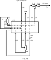
- a process for purifying crude carbon dioxide fluid comprising at least one "light” impurity and at least one "heavy” impurity comprising:
- first and second column systems operate above the triple point pressure and below the critical pressure of carbon dioxide
- said process comprises at least one heat pump cycle using as working fluid carbon dioxide-containing fluid from said second column system;
- said second column system is re-boiled by at least partially vaporizing at least one "heavy" impurity-enriched liquid in or taken from said second column system by indirect heat exchange against carbon dioxide-containing vapor from said second column system;
- said overhead vapor from said first column system comprises carbon dioxide and at least a portion of said carbon dioxide is recovered from said overhead vapor to produce "light" impurity-rich residual gas and recovered carbon dioxide;
- Suitable “heavy” impurity-enriched liquids in or taken from the second column system include “heavy” impurity-enriched bottoms liquid; and “heavy” impurity-enriched liquid(s) in or taken from at least one intermediate location in the second column system (i.e. "intermediate liquid”).
- apparatus for purifying crude carbon dioxide fluid comprising at least one "light” impurity and at least one "heavy” impurity, said apparatus comprising:
- said third heat exchanger is arranged to re-boil said second column system by vaporizing "heavy" impurity-enriched liquid in or taken from said second column system by said indirect heat exchange against said condensing carbon dioxide recycle gas; and wherein the apparatus further comprises a conduit arrangement for feeding recovered carbon dioxide from said carbon dioxide recovery system to said second column system for mass transfer separation.
- apparatus for purifying crude carbon dioxide fluid comprising at least one "light” impurity and at least one "heavy” impurity, said apparatus comprising:
- said second heat exchanger is arranged to at least partially condense carbon dioxide-enriched overhead vapor from said second column system by said indirect heat exchange against said vaporizing expanded "heavy" impurity-enriched liquid;
- apparatus further comprises a conduit arrangement for feeding recovered carbon dioxide from said carbon dioxide recovery system to said second column system for mass transfer separation.
- the first column system is for removal (or "rejection") of the "light” impurities from the crude carbon dioxide and thus may be referred to as a "lights" removal (or rejection) column system.
- the first column system usually comprises one or more distillation column systems for removing (or rejecting) one or more "light” impurity.
- the first column system may comprise a first distillation column system for removing (or rejecting) at least a first "light” impurity, e.g. helium, and a second distillation column system for removing (or rejecting) at least a second "light” impurity, e.g. nitrogen.
- the second column system is for removal of the "heavy" impurities from the "light” impurity depleted carbon dioxide produced in the first column system and thus may be referred to as a "heavies" removal column system.
- One advantage of preferred embodiments of the present invention is that overall energy consumption is reduced significantly.
- the reduction is achieved because the purity of the working fluid in the heat pump cycle is increased thereby enabling the recycle stream to condense over a narrower range of temperature which allows a closer average temperature approach when re-boiling the second column system.
- the recycle pressure can be reduced which enables a reduction in compression power required in the heat pump cycle.
- a further advantage of preferred embodiments is that the overall recovery of carbon dioxide is improved significantly. The improvement is achieved as it is no longer necessary to purge working fluid from the heat pump cycle to prevent build up of "light” impurities. In addition, carbon dioxide is recovered from the overhead from the first column system.
- references herein to pressure are references to absolute pressure and not gauge pressure unless expressly stated otherwise.
- references to "light impurity” and “heavy impurity” should be interpreted as references to “light impurities” and “heavy impurities” as appropriate depending on the number of such impurities present in the crude carbon dioxide fluid.
- fluid compositions are calculated in mol. % on a “dry” basis, i.e. excluding any water content from the calculations. In reality, to avoid operating problems, water content must be low enough to avoid freeze-out and/or hydrate formation, i.e. the crude carbon dioxide should have a water content of no more than 10 ppm.
- the present invention involves a process for purifying crude carbon dioxide fluid comprising at least one "light” impurity and at least one "heavy” impurity.
- the process comprising cooling the crude carbon dioxide fluid above the triple point pressure of carbon dioxide by indirect heat exchange to produce cooled crude carbon dioxide fluid.
- the cooled crude carbon dioxide fluid is fed to a first column system for mass transfer separation to produce "light" impurity-enriched overhead vapor and "light” impurity-depleted carbon dioxide bottoms liquid comprising the "heavy” impurity.
- the first column system is re-boiled by indirect heat exchange to provide vapor for the first column system.
- the bottoms liquid is fed from the first column system to a second column system for mass transfer separation to produce carbon dioxide overhead vapor and bottoms liquid enriched with the "heavy" impurity.
- Reflux for the second column system is provided using a carbon dioxide-enriched liquid and the second column system is re-boiled by indirect heat exchange to provide vapor for the second column system.
- the first and second column systems operate above the triple point pressure of carbon dioxide, i.e. above about 5.2 bar, and below the critical pressure of carbon dioxide, i.e. below about 73.9 bar.
- the process comprises at least one heat pump cycle using as working fluid carbon dioxide-containing fluid from the second column system.
- the second column system is reboiled by at least partially vaporizing at least one "heavy" impurity-enriched liquid in or taken from the second column system, by indirect heat exchange against carbon dioxide-containing vapor from the second column system.
- the "heavy" impurity-enriched liquid may be "heavy" impurity-enriched bottoms liquid, at least one "heavy” impurity-enriched liquid in or taken from an intermediate location in the second column system, or a combination of such liquids.
- the second column system is reboiled in part by vaporizing an "heavy" impurity-enriched intermediate liquid by indirect heat exchange against the carbon dioxide-containing vapor.
- "Heavy" impurity-enriched bottoms liquid is also vaporized by indirect heat exchange, possibly against another "warm” process stream, to provide further vapor for the second column system.
- the overhead vapor from the first column system comprises carbon dioxide, at least a portion of which is recovered from the overhead vapor to produce "light" impurity-rich residual gas and recovered carbon dioxide.
- the recovered carbon dioxide may be either recycled to an appropriate point in the process, or fed to the second column system for mass transfer separation.
- mass transfer separation the Inventors mean processes involving distillation (or rectification or fractionation), scrubbing, stripping or washing.
- the expression is intended to include processes in which heat is also transferred.
- mass transfer separation in the first and second column systems is by distillation.
- re-boiling the Inventors mean that liquid present in a column system is vaporized, typically by indirect heat exchange against a warmer process stream, to produce vapor for the column system and facilitate the mass transfer separation. Bottoms liquid and/or liquid from an intermediate point in the column system may be re-boiled. The liquid may be re-boiled within the column using an in situ re-boiler, or may be re-boiled outside the column, for example using a side re-boiler which may be a discrete unit, or may be a zone in a larger heat exchange unit.
- the crude carbon dioxide fluid may be taken from any suitable source.
- the crude carbon dioxide fluid is derived from a natural source of carbon dioxide.
- the crude carbon dioxide fluid may originate from enhanced oil recovery (EOR) processes.
- crude carbon dioxide from the field will often be reduced in pressure or temperature to "knock out” water, dissolved sulfur compounds and heavier hydrocarbons.
- crude carbon dioxide would typically be reduced to low pressure, e.g. less than 5 bar. In such case, the crude carbon dioxide would be recompressed prior to processing using the present invention.
- the concentration of water in the crude carbon dioxide may be further reduced to reduce the potential for condensation or hydrate formation within the present invention.
- the dehydration step could be performed with an adsorption system or a solvent-based system, for example using a glycol mixture as a solvent.
- the pressure of the crude carbon dioxide fluid is typically above the triple point pressure for carbon dioxide (i.e. about 5.2 bar) and usually no more than 200 bar. Since the critical pressure of carbon dioxide is about 73.9 bar, the crude carbon dioxide fluid may be below, at or above the critical pressure for carbon dioxide. In some embodiments, the pressure of the crude carbon dioxide fluid is from about 100 bar to about 200 bar. In other embodiments, the pressure of the crude carbon dioxide fluid is from about 20 bar to about 100 bar, e.g. from about 30 bar to about 80 bar.
- the temperature of the crude carbon dioxide fluid is typically no less than -20°C, usually no less than -10°C, and preferably no less than 0°C.
- the temperature may be above the critical temperature for carbon dioxide, i.e. about 31.1°C.
- the temperature of the crude carbon dioxide fluid is typically no more than 100°C, usually no more than 50°C and preferably no more than 30°C. In some embodiments, the temperature is no more than 20°C, or even no more than 15°C.
- the temperature may be about the "bubble point" of carbon dioxide, i.e. the temperature at which the carbon dioxide begins to boil at a given pressure. In other embodiments, the temperature is at or above the dew point of carbon dioxide.
- the present invention is intended to process crude carbon dioxide fluid at flow rates typically from about 50 to about 100,000 kmol/h (or 1 to 2000 million standard cubic feet per day or MMSCFD), e.g. about 500 to about 50,000 kmol/h (or 10 to 1000 MMSCFD). Individual plants would process typically about 2,500 to about 10,000 kmol/h (or 50 to 200 MMSCFD) but multiple plants may be used in parallel.
- the crude carbon dioxide fluid typically comprises at least 50 mol. %, e.g. at least 65 mol. % and preferably at least 80 mol. % carbon dioxide.
- the crude carbon dioxide fluid typically comprises no more than 97 mol. %, e.g. no more than 95 mol. %, carbon dioxide.
- the crude carbon dioxide comprises from about 85 mol. % to about 95 mol. % carbon dioxide.
- Typical "heavy" impurities include hydrogen sulfide; methanol; C 3 to C 8 hydrocarbons such as propane; carbon disulfide; carbon oxysulfide; dimethyl sulfide and other organic sulfur compounds; nitrogen dioxide; sulfur dioxide; sulfur trioxide; and ammonia, and the present invention may be applied to the removal of any one, or any mixture, of these impurities or other "heavy” impurities.
- the total concentration of the "heavy" impurities in the crude carbon dioxide fluid is typically no more than 50 mol. %, for example no more than 25 mol %, e.g. no more than 10 mol. %.
- the total concentration of the "heavy" impurities in the crude carbon dioxide fluid is typically at least 0.1 mol. %, for example at least 0.2 mol. %, e.g. at least 0.5 mol. % or 1 mol. %.
- the invention has particular application in the removal of hydrogen sulfide as a "heavy" impurity.
- concentration of hydrogen sulfide may be from about 0.1 mol. % to about 25 mol. %, e.g. from about 0.2 mol. % to about 10 mol. %.
- Typical "light” impurities include nitrogen; oxygen; neon; krypton; argon; xenon; hydrogen; helium; methane; C 2 hydrocarbons such as ethane; carbon monoxide; nitric oxide; and nitrous oxide, and the present invention may be applied to the removal of any one or any mixture of these impurities or other "light” impurities.
- the total concentration of the "light” impurities in the crude carbon dioxide fluid is typically no more than 50 mol. %, for example no more than 25 mol %, e.g. no more than 10 mol. %.
- the total concentration of the "light” impurities in the crude carbon dioxide fluid is typically at least 0.1 mol. %, for example at least 0.2 mol. %, e.g. at least 0.5 mol. % or 1 mol. %.
- the present invention has particular application in the removal of hydrogen sulfide as a "heavy" impurity.
- the "light” impurities are typically one or more of nitrogen, argon, helium, methane and ethane.
- the total concentration of "light” impurities in such cases may be from about 0.5 mol. % to about 50 mol. %, e.g. from about 1 mol. % to about 25 mol. %.
- the fluid is typically condensed on cooling. In embodiments where the crude carbon dioxide fluid is supercritical, the fluid is "pseudo-condensed" on cooling. Typically, the crude carbon dioxide fluid is cooled to a temperature in the range from about 0°C to about -55°C.
- the cooled crude carbon dioxide fluid is usually expanded prior to being fed to the first column system. Prior to expansion, the cooled crude carbon dioxide fluid may be below, at or above the critical pressure for carbon dioxide. However, after expansion, the pressure of the fluid is sub-critical.
- the feed to the first column system is typically two phase with the liquid phase containing predominantly carbon dioxide and heavy impurity and the vapor phase containing predominantly "light” impurities. In embodiments where there is only a small amount of "light” impurities in the crude carbon dioxide fluid, then the feed is predominantly liquid.
- the "light” impurities are removed from the crude carbon dioxide fluid by mass transfer separation in the first column system.
- the operating pressure(s) of the first column system is typically from about 10 bar to about 60 bar, e.g. from about 30 bar to about 60 bar, and operating temperature(s) is typically from about -55°C to about 25°C.
- the first column system typically comprises a single distillation column system to which the cooled crude carbon dioxide fluid is fed for mass transfer separation to produce the "light” impurity-enriched overhead vapor and the "light” impurity-depleted carbon dioxide bottoms liquid.
- one of the light impurities may be more valuable than the other(s). In which case, it may be desirable to recover the more valuable "light” impurity separately from the other "light” impurities. Examples of such cases would include situations where the "light” impurities include hydrogen or helium which are more volatile (and potentially more valuable) than other "light” impurities such as nitrogen, oxygen, argon and methane.
- the process may comprise different steps for removing the "light” impurities.
- the first column system may comprise a plurality of distillation column systems, for example a first distillation column system and a second distillation column system.
- the process may comprise feeding the cooled crude carbon dioxide fluid to the first distillation column system to produce overhead vapor enriched in the first "light” impurity, and bottoms liquid depleted in the first "light” impurity; re-boiling the first distillation column system by indirect heat exchange to provide vapor for the first distillation column system; feeding bottoms liquid from the first distillation column system to the second distillation column system to produce the "light" impurity-enriched overhead vapor and the "light” impurity depleted carbon dioxide bottoms liquid; and feeding bottoms liquid from the second distillation column system to the first distillation column system, preferably as reflux.
- the bottoms liquid from the first distillation column system is typically expanded prior to being fed to the second distillation column system.
- the bottoms liquid from the second distillation column system is preferably pumped prior to being fed to the first distillation column system.
- reflux for the first distillation column system may be provided using carbon dioxide-enriched liquid from the second column system.
- the bottoms liquid from the second distillation column system may be fed to an intermediate location in the first distillation column system.
- the carbon dioxide-enriched liquid from the second column system is preferably pumped prior to being fed as reflux to the first distillation column system.
- the first and second distillation column systems both operate within the broad range of pressures and temperatures identified above. However, in preferred embodiments, the first distillation column system operates at a pressure of about 40 bar to about 60 bar and a feed temperature from about -55°C to about 10°C, and the second distillation column system operates at a pressure of about 30 bar to about 50 bar and a feed temperature from about -30°C to about 10°C.
- the first column system recovers methane in a methane-enriched overhead vapor. If nitrogen is also present as a "light” impurity, then the methane-enriched overhead vapor also contains nitrogen and the overhead vapor may then be subjected to a nitrogen rejection process to recover the methane.
- the "light" impurities are methane, nitrogen and helium
- the crude carbon dioxide fluid is typically a vapor that is at least partially condensed during the initial cooling step to produce the cooled crude carbon dioxide fluid which is preferably expanded prior to being fed to the first column system.
- re-boiling duty for the first column system is usually provided at least in part by indirect heat exchange against condensing crude carbon dioxide fluid.
- the re-boiling duty may be provided at least in part by indirect heat exchange against condensing recycle fluid in the heat pump cycle.
- Overhead vapor from the first column system contains carbon dioxide.
- the Inventors propose recovering carbon dioxide from this vapor to improve overall carbon dioxide recovery.
- the temperature of the overhead vapor from the first column system when fed to the carbon dioxide recovery step depends on the nature of the recovery process.
- the temperature of the overhead vapor may be reduced or increased or even remain unchanged after the overhead vapor is removed from the first column system.
- the overhead vapor is cooled to condense carbon dioxide to facilitate separation from the "light" impurities which would remain uncondensed. This is referred to herein as "cold" recovery of carbon dioxide.
- the refrigeration duty required to cool and partially condense the overhead vapor from the first column system may provided by indirect heat exchange against any suitable process stream, for example evaporating recovered carbon dioxide after expansion.
- the refrigeration duty may be provided by a combination of indirect heat exchange against a process stream and direct heat exchange with a colder washing liquid in a wash column.
- carbon dioxide is recovered from the overhead vapor by partial condensation and phase separation.
- the overhead vapor from the first column system is cooled by indirect heat exchange to condense carbon dioxide in the vapor which is then recovered by phase separation.
- the overhead vapor from the first column system is cooled by indirect heat exchange to condense carbon dioxide and the partially condensed fluid is fed to a wash column in which "heavy" impurities are washed out of the uncondensed vapor.
- Carbon dioxide-enriched liquid from the second column system is used to wash the uncondensed vapor in the wash column.
- the overhead vapor from the first column system may be cooled further by direct heat exchange with the washing liquid in the wash column.
- the liquid/vapor (“L/V”) ratio in the wash column is typically low in order to wash the small quantity of "heavy” impurities out of the "light” impurity-enriched vapor.
- the L/V ratio is typically less than 1, e.g. less than 0.5 or even less than 0.2.
- recovery typically takes place at a pressure that is as high as possible and/or practicable within the process, and at a temperature that is as low as possible and/or practicable within the process so as to maximize the recovery of carbon dioxide.
- the pressure is typically the same as the operating pressure of the part of the first column system from which the overhead vapor is taken (usually allowing for inherent pressure drop).
- the temperature is typically just above, e.g. a few degrees centigrade, or 1 to 3°C, above the temperature at which carbon dioxide would "freeze out” of the vapor.
- carbon dioxide may recovered from the overhead vapor from the first column system using a process selected from the group consisting of adsorption; absorption; membrane separation; and solidification and separation at a temperature below the triple point temperature for carbon dioxide.
- Suitable adsorption processes include Temperature Swing Adsorption (TSA), Vacuum Swing Adsorption (VSA) and Pressure Swing Adsorption (PSA).
- Suitable absorption processes include amine-based systems or other chemical or physical solvent systems. Examples of suitable absorption processes include Selexol® and Rectisol®.
- the recovered carbon dioxide may be sufficiently pure to be combined directly to the product rather than being fed to the first column system.
- Suitable membrane systems include polymeric membranes such as PRISM® membranes (Air Products and Chemicals, Inc.).
- the solid carbon dioxide is separated by any suitable means from the residual gas at a temperature below the triple point temperature for carbon dioxide.
- the invention covers the use of a supersonic separator and hydrate separator supplied by Twister BV in this context.
- the "light" impurity-rich residual gas is warmed by indirect heat exchange and purged from the process.
- at least a portion of the "light” impurity-rich gas may warmed by indirect heat exchange and added to carbon dioxide gas removed as product from the second column system.
- the purity of the carbon dioxide recycle stream(s) in the heat pump cycle(s) may be increased so that the streams condense over a narrower temperature range, thereby enabling a better match of the boiling temperature profile of the reboiler of the second column system.
- the "light" impurity-rich residual gas may be used as a fuel for combustion to produce combustion product gas.
- heat is preferably recovered from the combustion product gas by indirect heat exchange.
- the recovered carbon dioxide is typically fed as a supplementary feed to the second column system for mass transfer separation.
- the recovered liquid is optionally heated by indirect heat exchange (so to avoid formation of solid carbon dioxide on expansion), expanded and vaporized by indirect heat exchange, prior to being fed to the second column system.
- the recovered carbon dioxide is flashed in a separator vessel prior to (optional heating and) expansion, the vapor phase typically being warmed by indirect heat exchange and purged from the process and the liquid phase being expanded, vaporized and fed to the second column system.
- the recovered carbon dioxide may be recycled to the process.
- the recovered carbon dioxide may either be recycled upstream of the "light” impurity separation step, or fed as reflux to the first column system, as the "light” impurities in this stream would otherwise contaminate the pure carbon dioxide product.
- the overhead vapor from the first column system may be warmed by indirect heat exchange and carbon dioxide may be recovered from the warmed stream using a membrane separation system and recycled.
- Carbon dioxide bottoms liquid from the first column system still comprises the or each "heavy” impurity but is typically at least substantially free of "light” impurities, e.g. contains less than 5 mol. %, and typically less than 1 mol %, "light” impurities depending on the final carbon dioxide purity requirement.
- the liquid is fed to the second column system for mass transfer separation to produce carbon dioxide overhead vapor and bottoms liquid enriched with the "heavy” impurity.
- the bottoms liquid from the first column system is subcooled prior to being fed to the second column system.
- the bottoms liquid from the first column system is expanded prior to being fed to the second column system.
- the bottoms liquid from the first column system may be subcooled by indirect heat exchange prior to being expanded.
- the bottoms liquid from the first column system is at least partially vaporized prior to being fed to the second column system.
- the bottoms liquid from the first column system may be subcooled by indirect heat exchange and optionally expanded prior to being at least partially vaporized.
- the bottoms liquid from the first column system may be expanded (without subcooling) prior to being at least partially vaporized.
- the operating pressure(s) of the second column system is typically at least 10 bar. This avoids having to operate the column system at a temperature that is excessively cold and means that the volumetric suction flow of the heat pump compressor is not excessive.
- the operating pressure(s) of the second column system is typically no more than about 40 bar, e.g. no more than about 30 bar. In preferred embodiments, the operating pressure(s) is no more than about 25 bar. At this pressure, the second column system operates sufficiently far from the critical pressure for the hydraulic parameters within the column to be comfortable.
- the temperature of the primary feed to the second column system is typically in the range from about -40°C to about 5°C.
- the second column system may comprise a single distillation column, a split distillation column where both parts of the column operate at the same pressure, or multiple distillation columns where the columns operate at different pressures. In the latter case, all of the operating pressures fall within the preferred ranges given above.
- the operating pressure of the higher pressure column is typically from about 15 bar to about 40 bar and the operating pressure of the lower pressure column is typically from about 10 bar to about 30 bar.
- the bottoms liquid from the first column system is preferably fed to an intermediate location in the second column system.
- the second column system typically contains distillation trays and/or packing (random and/or structured), together with liquid redistributors etc., to increase vapor/liquid and thereby improve mass transfer separation.
- the second column system typically comprises at least two distillation sections with an intermediate zone between adjacent distillation sections. This intermediate zone is typically the feed location for the bottoms liquid from the first column system to the second column system.
- adjacent distillation sections the Inventors mean that there is no other distillation section between them.
- the "adjacent" distillation sections may be within the same distillation column system, e.g. in a single distillation column system, or may be in different distillation column systems, e.g. in a split or multiple distillation column system.
- the adjacent distillation sections may be in vertically and/or laterally spaced apart relation. Where the adjacent distillation sections are in laterally spaced apart relation, it may be necessary to pump liquid from one distillation section to the other, depending on the position of the distillation sections relative to each other.
- the second column system is typically re-boiled by at least partially vaporizing liquid in or taken from an intermediate location in the second column system.
- the intermediate liquid may be in or taken from the same intermediate zone as the feed location, or may be in or taken from a different intermediate zone in the second column system below said feed location, i.e. with at least one distillation section there between.
- the second column system is typically re-boiled by at least partially vaporizing bottoms liquid produced in the second column system.
- the reboiler may be in the sump of the column system, or may be located outside the column.
- the second column system may also comprise at least one vapor/liquid separator; one separator to separate a vapor component from reflux liquid for the column system; and/or a different separator to separate a liquid component from vapor for the column system generated from partially re-boiled liquid taken from the column system.
- Carbon dioxide-enriched overhead vapor has a greater concentration of carbon dioxide than the crude carbon dioxide fluid.
- concentration of carbon dioxide in the overhead vapor is typically at least 90 mol. %, e.g. at least 95 mol. % and preferably at least 98 mol. %.
- the overhead vapor is preferably substantially pure carbon dioxide containing no more than 200 ppm, preferably no more than 100 ppm, of "heavy" impurities.
- the bottoms liquid produced in the second column system comprises at least substantially all, and preferably essentially all, of any "heavy" impurity present in the crude carbon dioxide fluid.
- the vapor flow in the bottom section of the distillation column system is reduced resulting in a reduction in the diameter of the bottom section of the column system.
- the total inventory of bottoms liquid is thereby reduced significantly where there is a higher concentration of the volatile impurities.
- a reduction in the amount of liquid inventory means that there is less liquid inventory to escape in the event of a catastrophic failure of the plant. This advantage is particularly important where the "heavy" impurity or, where there is more than one, at least one of the "heavy” impurities is toxic, for example, in cases where the impurity is hydrogen sulfide.
- the process also provides carbon dioxide-enriched liquid for use as reflux for the second column system, and a portion of the bottoms liquid is at least partially re-boiled by indirect heat exchange to provide vapor for the column system. Carbon dioxide-enriched overhead vapor is removed from the column system, as is a portion of the bottoms liquid, or a liquid derived from bottoms liquid.
- Re-boiling duty for at least the second column system is provided at least in part by indirect heat exchange against recycle fluid(s) from at least one heat pump cycle using a carbon dioxide-containing vapor originating from the second column system as working fluid. Where there is more than one recycle fluid, at least one of the recycle fluids may a different pressure from the other recycle fluid(s).
- heat pump cycle the Inventors are referring to a cycle by which thermal energy is transferred from a heat source, which is at lower temperature, to a heat sink, which is at higher temperature.
- the heat pump cycle uses a working fluid which in this case is a carbon dioxide vapor from the second column system.
- the working fluid is removed from the second column system; at least partially vaporized (optional); warmed; compressed; and recycled to the column system after suitable cooling (and optional at least partially condensation) and pressure reduction.
- the compressed fluid, or "recycle fluid” is used to provide re-boil duty by indirect heat exchange with "heavy" impurity-enriched liquid(s) in or taken from the second column system, typically “heavy” impurity-enriched intermediate liquid(s).
- the recycle fluid(s) are cooled to a certain extent as a result of providing the re-boil duty but typically require further cooling before being returned to the second column system.
- the heat source is the overhead vapor that typically condenses at a lower temperature than the re-boiler (the heat sink).
- the Inventors have observed that, by compressing the overhead vapor in the heat pump cycle, the vapor transfers heat to the re-boiler and is condensed at a higher temperature than the reboiler.
- the working fluid is carbon dioxide depleted in "heavy" impurity and typically selected from the group consisting of carbon dioxide-enriched overhead vapor or carbon dioxide-enriched vapor taken from an intermediate location in the second column system ("intermediate vapor").
- intermediate vapor is used as the working fluid.
- the present invention may involve at least two recycle fluids at different pressures.
- the pressure differential is significant, typically of the order of at least 10%, e.g. at least 25% or even at least 50%, although the pressure differential is usually no more than 200%, e.g. no more than 100%.
- the pressure differential may be at least 2 bar, e.g. at least 5 bar and preferably at least 10 bar.
- the pressure differential is usually no more than 50 bar and preferably no more than 30 bar.
- the process comprises a single heat pump cycle having one or more recycle fluids.
- the pressure of that fluid is typically from about 15 bar to about 60 bar.
- the process may comprise a first recycle fluid and a second recycle fluid, the second recycle fluid having a pressure that is greater than that of the first recycle fluid.
- the pressure of the first recycle fluid is typically from about 15 bar to about 30 bar.
- the pressure of the second recycle fluid is typically about 20 bar to about 70 bar.
- the working fluid of the heat pump cycle comprises carbon dioxide-enriched gas generated by warming the carbon dioxide-enriched overhead vapor by indirect heat exchange. At least a portion of the duty required to warm the carbon dioxide-enriched overhead vapor may be provided by indirect heat exchange against any suitable "warm” process stream but is preferably provided by indirect heat exchange against at least one of the recycle fluids.
- the compressor feed may be warmed against the compressor products so that the flows on both sides of the heat exchanger are the same. In these embodiments, both the first and second recycle fluids are used to warm the overhead vapor.
- the recycle fluid(s) are typically recycled to an appropriate location in the second column system after suitable pressure reduction.
- the appropriate location in the second column system is typically where the composition in the column matches the composition of the recycle fluids.
- condensed recycle fluid is typically recycled as reflux to the second column system.
- the ratio of molar flow of the first recycle fluid to the second recycle fluid is determined by the duty required of the fluids.
- the molar flow ratio is from about 0.1 (i.e. 1:10) to about 15 (i.e. 15:1). In some preferred embodiments, this ratio is from about 3 (i.e. 3:1) to about 12 (i.e. 12:1). In other preferred embodiments, the ratio is from about 0.2 (i.e. 1:5) to about 1 (i.e. 1:1).
- the working fluid of the heat pump cycle comprises "heavy" impurity-enriched gas generated by vaporizing liquid taken from said second column system by indirect heat exchange after suitable pressure reduction.
- the liquid is an "heavy" impurity-enriched liquid taken from an intermediate location in the second column system or the bottom of said column system.
- the intermediate liquid is removed from a location that is at least substantially level (or below) with the location of the main feed to the second column system.
- the composition of the intermediate liquid is usually at least substantially identical to that of the carbon dioxide feed to the second column system.
- the working fluid may also comprise carbon dioxide gas generated by warming the carbon dioxide overhead vapor by indirect heat exchange.
- At least a portion of the duty required to evaporate said "intermediate" liquid may also be provided by any suitable "warm” process stream.
- the intermediate liquid is evaporated by indirect heat exchange against condensing overhead vapor from the second column system.
- the first recycle fluid is preferably recycled as part of the feed to the second column system and, additionally or alternatively, the second recycle fluid is preferably recycled as part of the working fluid for the heat pump cycle after suitable pressure reduction.
- the process may comprise at least a first heat pump cycle and a second heat pump cycle, each heat pump cycle comprising at least one recycle fluid.
- the recycle fluid of the first heat pump cycle or, where the first heat pump cycle has more than one recycle fluid, at least one of the recycle fluids, has a pressure that is greater than that of a recycle fluid of the second heat pump cycle.
- the working fluid of the first heat pump cycle preferably comprises carbon dioxide-enriched gas generated by warming the carbon dioxide-enriched overhead vapor by indirect heat exchange. At least a portion of the duty required to warm the carbon dioxide-enriched overhead vapor may be provided by indirect heat exchange against any suitable "warm” process stream although, in preferred embodiments, it is provided by indirect heat exchange against at least one of the recycle fluids.
- the pressure of the recycle fluid of the first heat pump cycle is typically from about 15 bar to about 60 bar.
- the working fluid of the second heat pump cycle may comprises carbon dioxide-enriched gas generated by warming "intermediate" vapor taken from an intermediate location of the distillation column system by indirect heat exchange.
- the "intermediate" vapor is a carbon dioxide-enriched fluid.
- the intermediate vapor is removed from a location that is at least substantially level with the location of the main feed to the column system.
- the composition of the intermediate vapor is usually at least substantially identical to that of the carbon dioxide feed.
- At least a portion of the duty required to warm the "intermediate" vapor may be provided by indirect heat exchange against any suitable "warm” process stream although, in preferred embodiments, it is provided by indirect heat exchange against at least one of the recycle fluids.
- the recycle streams are usually recycled to appropriate locations in the second column system after suitable pressure reduction if required.
- the first recycle fluid is preferably condensed and recycled after pressure reduction to the top of the second column system to provide reflux.
- the second recycle fluid is usually recycled after suitable pressure reduction if required to an intermediate location in the second column system that is at least substantially level with the location of the main feed to the column system.
- the working fluid for the second heat pump cycle is intermediate vapor from the lower pressure column and is recycled without pressure reduction to the bottom of the higher pressure column.
- the pressure of the recycle fluid of the second heat pump cycle is preferably from about 10 bar to about 25 bar, e.g. the operating pressure of the part of the second column system to which the recycle fluid is recycled.
- Bottoms liquid alone, or both bottoms liquid and at least one liquid from an intermediate location in the second column system is preferably at least partially re-boiled by indirect heat exchange to provide vapor for the second column system.
- At least a portion of the re-boiling duty, particularly for intermediate liquid(s) may be provided by indirect heat exchange against any suitable "warm” process stream although, in preferred embodiments, it is provided by indirect heat exchange against at least one of the recycle fluids, e.g. the first recycle fluid which is at least partially condensed as a result.
- an advantage of using the intermediate reboiler is that the pressure to which the working fluid must be compressed is reduced thereby saving power.
- an advantage of using an intermediate re-boiler is that the power consumption is significantly reduced by only needing to compress a fraction (typically ⁇ 10%) of the overhead vapor to the higher pressure required to heat the bottom re-boiler, whilst the rest only needs to be compressed to the lower pressure.
- a further advantage of the intermediate re-boiler for all embodiments is that the column diameter below the reboiler, where the hydrogen sulfide concentration increases rapidly, can be significantly reduced so that the inventory of highly toxic hydrogen sulfide can be reduced.
- the reflux for the second column system is preferably provided by at least one recycle fluid condensate, typically condensed overhead vapor, after suitable pressure reduction.
- the reflux for the column is provided by an overhead condenser arrangement in which overhead vapor is at least partially condensed by indirect heat exchange against at least one "cold" process stream, e.g. re-boiling intermediate or bottoms liquid, and returned to the column system.
- the refrigeration duty required to cool and at least partially condense at least one recycle fluid may be provided by indirect heat exchange against any suitable "cold" process stream.
- cooling duty the Inventors mean the cooling duty and, if applicable, the condensing duty required by the process.
- cold process stream the Inventors mean any fluid stream within the process whose temperature is lower than that of the fluid to be cooled and, where appropriate, condensed and whose pressure is suitable to provide the necessary indirect heat exchange.
- Suitable "cold" process streams include streams entering a main heat exchange at the cold end.
- the duty is provided by indirect heat exchange against at least one fluid selected from the group consisting of carbon dioxide-enriched liquid; intermediate liquid; bottoms liquid; liquid derived from bottoms liquid; and expanded crude carbon dioxide fluid.
- the crude carbon dioxide fluid is cooled by indirect heat exchange prior to separation. At least a portion of the refrigeration duty required to cool and optionally condense the crude carbon dioxide fluid may be provided by indirect heat exchange with any suitable refrigerant stream although, in preferred embodiments, it is provided by indirect heat exchange against at least one "cold" process stream selected from the group consisting of carbon dioxide-enriched liquid; intermediate liquid; bottoms liquid from any column system; liquid derived from bottoms liquid; and expanded crude carbon dioxide fluid.
- the "light" impurity-depleted carbon dioxide bottoms liquid from the first column system is preferably used as a "cold" process stream to provide refrigeration duty for the process.
- the liquid may also be used as a "warm” process stream since it is typically subcooled by indirect heat exchange.
- the subcooled stream is typically expanded and then can be used as a "cold” stream when vaporized by indirect heat exchange.
- the liquid may also be fed directly to the distillation column stream without providing refrigeration duty by indirect heat exchange.
- the feed may be derived from supercritical crude carbon dioxide fluid and carbon dioxide liquid is produced as a product.
- the carbon dioxide liquid is typically removed from the second column system, pumped and warmed by indirect heat exchange to produce warmed carbon dioxide liquid as a product.
- At least a portion of the duty required to warm the pumped carbon dioxide liquid may be provided by indirect heat exchange against any suitable "warm” process stream although, in preferred embodiments, it is provided by indirect heat exchange against at least one of the recycle fluids.
- the pumped carbon dioxide liquid is preferably used as a "cold" process stream to provide refrigeration duty for the process.
- the feed may be derived from crude carbon dioxide vapor and carbon dioxide gas is produced as a product.
- a portion of the carbon dioxide overhead vapor from the second column system is typically warmed by indirect heat exchange to produce the carbon dioxide gas.
- At least a portion of the duty required to warm said carbon dioxide overhead vapor may be provided by indirect heat exchange with any suitable "warm" process stream although, in preferred embodiments, it is provided by indirect heat exchange against at least one of the recycle fluids.
- the carbon dioxide overhead vapor is preferably used as a "cold" process stream to provide refrigeration duty for the process.
- a portion of bottoms liquid from the second column system, or liquid derived from said bottoms liquid, is usually pumped to provide "heavy" impurity-rich waste liquid. Since the pumped liquid is typically a small stream near ambient temperature, there may be no need to or advantage to warm it by indirect heat exchange, before disposal as a waste liquid. However, in embodiments in which the liquid is significantly below ambient temperature, the liquid may be used as a "cold" stream to provide refrigeration duty. At least a portion of the duty required to warm the pumped bottoms liquid may be provided by indirect heat exchange against any "warm” process stream although, in preferred embodiments, it is provided by indirect heat exchange against at least one of the recycle fluids.
- the further portion of the bottoms liquid, or the liquid derived from bottoms liquid, is typically used as a "cold" process stream to provide refrigeration duty for the process.
- An external refrigeration cycle may be used to provide at least a portion of the refrigeration duty required by the process, e.g. to cool the feed to the process thereby producing the cooled carbon dioxide fluid.
- the entire process is auto-refrigerated, i.e. none of the refrigeration duty is provided by an external refrigeration cycle.
- the apparatus comprises:
- the apparatus comprises:
- Fluid flow communication the Inventors mean that the relevant parts of the apparatus are operationally arranged and/or interconnected such that fluid may flow between the parts as indicated. Fluid flow communication may be provided in any suitable way although the use of conduit arrangements, such as piping, is preferred. Fluid flow communication may also include, for example, pressure reduction arrangements, such as expansion valves; channels in a heat exchanger; and/or phase separation vessels, as required.
- the apparatus comprises a conduit arrangement for feeding recovered carbon dioxide from the carbon dioxide recovery system to the second column system for mass transfer separation.
- the apparatus preferably comprises a second pressure reduction arrangement, such as an expansion valve, provided in the fluid flow communication between the first heat exchanger and the first column system for expanding the cooled crude carbon dioxide fluid.
- a second pressure reduction arrangement such as an expansion valve
- the apparatus preferably comprises a fourth heat exchanger provided in the fluid flow communication between the first column system and the carbon dioxide recovery system for cooling the overhead vapor from the first column system by indirect heat exchange.
- the carbon dioxide recovery system comprises:
- the carbon dioxide recovery system comprises:
- the second column system typically comprises:
- the third heat exchanger is typically arranged to re-boil liquid in or taken from the intermediate zone of the second column system to which bottoms liquid from the first column system is fed, or another intermediate zone.
- the apparatus comprises a third pressure reduction arrangement, such as an expansion valve, in the fluid flow communication between the first heat exchanger and the first column system for expanding the crude carbon dioxide fluid.
- a third pressure reduction arrangement such as an expansion valve
- the first re-boiler is preferably at least a part of the first heat exchanger, the first heat exchanger being arranged to re-boil the bottoms liquid produced by the first column system by the indirect heat exchange against the condensing crude carbon dioxide fluid.
- the first re-boiler may be at least a part of the third heat exchanger, the third heat exchanger also being arranged to re-boil the bottoms liquid produced by the first column system by the indirect heat exchange against the condensing carbon dioxide fluid.
- the first or second column system may comprise a distillation (or rectification or fractionation) column system, a scrubbing column system, a stripping column system or a wash column system.
- the first or second column system comprises a distillation column system.
- the first column system typically comprises at least one distillation column system.
- the first column system may comprise:
- the apparatus may also comprise a conduit arrangement for providing carbon dioxide-enriched liquid from the second column system as reflux to the first distillation column system.
- the conduit arrangement for providing carbon dioxide-enriched liquid from the second column system as reflux to the first distillation column system may comprise a second pump for pumping carbon dioxide liquid from the second column system to the first distillation column system.
- the apparatus preferably comprises a fourth pressure reduction arrangement, such as an expansion valve, in the fluid flow communication between the first and second distillation column systems for expanding said bottoms liquid from said first distillation column system prior to being fed to said second distillation column system.
- a fourth pressure reduction arrangement such as an expansion valve
- the apparatus preferably comprises a sixth heat exchanger in the fluid flow communication between the first column system and the second column system for subcooling bottoms liquid from the first column system by indirect heat exchanger prior to feeding to the second column system.
- the apparatus preferably comprises a fifth pressure reduction arrangement, such as an expansion valve, in the fluid flow communication between the first column system and the second column system for expanding bottoms liquid from the first column system prior to feeding to the second column system.
- a fifth pressure reduction arrangement such as an expansion valve
- the apparatus preferably comprises a seventh heat exchanger in the fluid flow communication between the first column system and the second column system for at least partially vaporizing bottoms liquid from the first column system prior to feeding to the second column system.
- the second heat exchanger is in fluid flow communication with the top portion of the second column system, thereby enabling the use of carbon dioxide overhead vapor as the working fluid of the heat pump cycle.
- the heat exchangers may be individual heat exchangers. However, in preferred embodiments, the heat exchangers are zones within at least one larger heat exchange unit. Preferably, the heat exchangers are zones within a single primary heat exchange unit which is typically a plate fin heat exchanger made of braized aluminum.
- the compressors may be individual compressors. However, in some embodiments, the compressors may be stages within one or more multistage intercooled compressor.
- the distillation column systems may also comprise at least one vapor/liquid separator to separate a vapor component from reflux liquid for the column system, and/or to separate a liquid component from vapor for the column system generated from partially re-boiled liquid taken from the column system.
- a stream 100 of crude carbon dioxide vapor is cooled and condensed by indirect heat exchange in main heat exchanger HE1 by indirect heat exchange to produce a stream 102 of crude carbon dioxide condensate.
- Stream 102 is expanded across expansion valve V2 to produce stream 104 of expanded crude carbon dioxide condensate which is then vaporized by indirect heat exchange in main heat exchanger HE1 to form stream 106 of crude carbon dioxide vapor and fed to distillation column system C1 for removal of the "heavy" impurities.
- Crude carbon dioxide is separated in a distillation column C1 into "heavy" impurity-depleted carbon dioxide overhead vapor and "heavy” impurity-enriched bottoms liquid.
- Reboil duty for the distillation column is provided at least in part by a recycle fluid in a heat pump cycle using overhead vapor as the working fluid.
- overhead vapor is removed and fed as stream 110 to the main heat exchanger HE1 where it is warmed by indirect heat exchange to produce stream 112 which is compressed in compressor CP1 to produce compressed carbon dioxide gas.
- the compressed gas is divided into two portions. The first portion is further compressed in compressor CP3 and then fed to a downstream process, e.g. FIG 1B , for removal of "light" impurities.
- the second portion is fed as recycle stream 120 to the main heat exchanger HE1 where it is cooled and partially condensed to form stream 122 of partially condensed carbon dioxide gas.
- Stream 122 is expanded across valve V4 to produce stream 124 which is phase separated in phase separator vessel S3.
- the separated vapor is combined with the overhead vapor from column C1 to form stream 110 and the separated liquid is returned to the top of the distillation column C1 as reflux.
- a stream 180 of "heavy" impurity-enriched bottoms liquid is removed from the distillation column C1 and partially vaporized by indirect heat exchange in the main heat exchanger HE1 against condensing feed.
- a stream 182 of partially vaporized bottoms liquid is fed to a phase separator S4 and the vapor phase is fed back to the column C1.
- the liquid phase is removed from the separator S4 as stream 186, pumped in pump P3, warmed by indirect heat exchange in HE1 to form a stream 190 of warmed bottoms liquid and pumped further in pump P4 to produce a stream 192 of waste liquid.
- a stream 170 of liquid taken from an intermediate location in the distillation column C1 is fed to HE1 where it is at least partially vaporized by indirect heat exchange against condensing recycle fluid from the heat pump cycle to produce a stream 172 of at least partially vaporized intermediate liquid which is fed back to the distillation column C1.
- a stream of carbon dioxide containing "light" impurities such as stream 160 in FIG. 1A , is fed to a heat exchange HE10 where it is cooled and partially condensed.
- the two-phase stream is phase separated in phase separator S10 into a vapor phase containing most of the "light” impurities and some carbon dioxide, and a liquid phase containing most of the carbon dioxide.
- the liquid phase 920 is expanded across valve V20, vaporized by indirect heat exchange in HE10 and compressed in CP20 to form the carbon dioxide product gas 930.
- Carbon dioxide is recovered from the vapor phase 940 from S10 by cooling and partially condensing the vapor phase by indirect heat exchange in HE10 and subsequent phase separation in phase separator S20.
- the further vapor phase 908 is warmed by indirect heat exchange in HE10 and purged from the process.
- the further liquid phase 912 is warmed by indirect heat exchange in HE10, expanded across valve V30, vaporized by indirect heat exchange in HE10, compressed in compressor CP10 and combined with the vaporized liquid phase from S10 prior to further compression in CP20 to produce the product gas 930.
- FIG. 2 The process depicted in FIG. 2 is a modification of the process of Figs 1A & 1B in which "light" impurities are removed from the feed to the process rather than from the carbon dioxide product.
- the features of FIG. 2 that are common to Figs 1A & 1B have been given the same reference numerals. The following is a discussion of the features of FIG. 2 that distinguish the process over that depicted in Figs 1A & 1B .
- Stream 100 of crude carbon dioxide vapor is cooled and condensed by indirect heat exchange in heat exchanger HE1 to form a stream 200 of condensed feed which is expanded across valve V1 and fed to a distillation column C3 of a first column system where it is separated into "light" impurity-enriched overhead vapor 156 and "light” impurity-depleted crude carbon dioxide liquid 204 comprising the heavy impurity.
- the overhead vapor 156 is cooled by indirect heat exchange in heat exchanger HE1 to form partially condensed "light" impurity-enriched fluid 210 which is phase separated in separator S2.
- the residual vapor rich in light impurity(s) 140 is warmed by indirect heat exchange in heat exchanger HE1 and purged from the process.
- the liquid phase containing recovered carbon dioxide 212 is expanded across valve V3, vaporized by indirect heat exchange in heat exchanger HE1 and then fed to the distillation column C1 of a second column system for mass transfer separation (stream 214).
- FIG. 3 The process depicted in FIG. 3 is a modification of the process of FIG. 2 in which the heat pump cycle has two recycle pressures.
- the features of FIG. 3 that are common to the previous figures have been given the same reference numerals. The following is a discussion of the distinguishing features of FIG. 3 .
- compressor CP3 Rather than being compressed in compressor CP3 and taken as product, the part of the exhaust from compressor CP1 that is not recycled is compressed to an intermediate pressure in compressor CP2 and divided into two portions. A first portion is fed to compressor CP3 for compression as in the previous figures. However, a second portion 130 is cooled by indirect heat exchange in HE1 to form condensed carbon dioxide fluid 132 at a second recycle pressure that is greater than the first recycle pressure. The fluid is then expanded across valve V5 and then combined with the first recycle fluid prior to phase separation in S3.
- a part 154 of the liquid carbon dioxide from separator S3 is pressurized in pump P1 and vaporized by indirect heat exchange in HE1 to form stream 158 which is then combined with the exhaust from compressor CP3 to form the carbon dioxide product 160.
- FIG. 4 is a modification of the process of FIG. 2 in which the single distillation column C1 of the second column system is replaced with a split distillation column C1/C2, in which part of the carbon dioxide-enriched fluid is taken as liquid and vaporized at two different pressures and in which the recovered carbon dioxide is warmed by indirect heat exchange prior to expansion and vaporization.
- the features of FIG. 4 that are common to the previous figures have been given the same reference numerals. The following is a discussion of the distinguishing features of FIG. 4 .
- the vapor phase 184 from separator S4 is fed to the base of distillation column C2 of the second column system.
- the overhead vapor from distillation column C2 is combined with the primary feed to distillation column C1 of the second column system.
- Distillation column C2 is re-boiled by indirect heat exchange against condensing feed in HE1.
- the bottoms liquid from distillation column C1 is divided into two portions.
- the first portion is used to provide reflux in distillation column C2.
- the second portion 170 is vaporized by indirect heat exchange against condensing recycle fluid in HE1 and returned to the distillation column C1 as stream 172.
- the recovered carbon dioxide 212 from S2 is warmed by indirect heat exchange in HE1 prior to being expanded across valve V3. Such warming is to ensure that no solid carbon dioxide is formed on expansion and enables the "light" impurity-enriched overhead vapor to be cooled further thereby improving recovery of carbon dioxide condensate in S2.
- the liquid is divided into two portions.
- the first portion is fed to the second column system as reflux and the second portion 154 is pumped in P1 and then divided into two parts.
- the first part 162 is expanded across valve V5, vaporized by indirect heat exchange in HE1, combined with the compressed carbon dioxide gas from CP2 and then compressed in CP3.
- the second part 156 is vaporized by indirect heat exchange in HE1, combined with the compressed carbon dioxide gas from CP3 and the combined gas 160 is taken as carbon dioxide product.
- FIG. 5 The process depicted in FIG. 5 is a modification of the process of FIG. 4 in which residual "heavy" impurity and carbon dioxide in the vapor phase of the "light" impurity-enriched overhead vapor from the first column system after cooling and partial condensation by indirect heat exchange in HE1 are washed out from the vapor phase and recovered.
- the recovered carbon dioxide 212 is not heated prior to expansion and vaporization.
- the overhead vapor 156 from distillation column C3 of the first column system is cooled and partially condensed by indirect heat exchange in HE1 and fed as stream 210 to wash column C4 where the vapor phase is washed using liquid carbon dioxide 232 from the second column system. Washing the vapor phase in this way enables residual "heavy" impurity and some of the carbon dioxide in the vapor phase to be recovered.
- the overhead vapor 140 from wash column C4 is warmed in HE1 and purged from the process.
- the bottoms liquid 212 is expanded in valve V3, vaporized in HE1 and forms the supplementary feed 214 to distillation column C1 of the second column system.
- the pumped carbon dioxide liquid from pump P1 is divided into three portions.
- the first and second portions are vaporized at different pressures and compressed to form the carbon dioxide product as in FIG. 4 .
- the third portion 230 is expanded across valve V6 and used as the washing liquid 232 in wash column C4.
- FIG. 6 The process depicted in FIG. 6 is a modification of the process of FIG. 5 in which the heat pump cycle has been modified.
- the features of FIG. 6 that are common to the previous figures have been given the same reference numerals. The following is a discussion of the distinguishing features of FIG. 6 .
- the entire flow 120 is cooled and condensed by indirect heat exchange in HE1, expanded across valve V4 and fed as reflux to distillation column C1 via separator S3 of the second column system.
- the entire feed 242 to compressor CP2 is provided by the carbon dioxide vapor 240 from separator S3 that has been warmed by indirect heat exchange in HE1.
- FIG. 7 The process depicted in FIG. 7 is a modification of the process of FIG. 5 with initial helium recovery.
- the features of FIG. 7 that are common to the previous figures have been given the same reference numerals. The following is a discussion of the distinguishing features of FIG. 7 .
- the condensed feed 250 is expanded across valve V8 and fed to an intermediate location in a distillation column C5 of the first column system where it is separated by mass transfer into helium-enriched overhead vapor 254 and helium-depleted crude carbon dioxide bottoms liquid 260.
- the overhead vapor is warmed by indirect heat exchange in HE1 to form a gaseous product 256 containing helium.
- distillation column C5 is reboiled by indirect heat exchange against condensing feed in HE1 with the vapor phase 264 being sent to column C5 and bottoms liquid 200 being fed to distillation column C3 of the first column system for mass transfer separation after expansion across valve V1.
- Reflux 274 for distillation column C5 is provided by a portion 270 of the bottoms liquid from distillation column C3 which is pumped in pump P2.
- Valve V7 is typically a control valve only and not an expansion valve.
- FIG. 8 The process depicted in FIG. 8 is a modification of the process of FIG. 7 in which the helium recovery column is provided with additional reflux using pure carbon dioxide liquid from the second column system.
- the features of FIG. 8 that are common to the previous figures have been given the same reference numerals. The following is a discussion of the distinguishing features of FIG. 8 .
- Part of the bottoms liquid from distillation column C3 of the first column system (stream 274) is fed to an intermediate location in distillation column C5 after pumping in pump P2.
- liquid carbon dioxide from separator S3 of the second column system is pumped in pump P1 and divided into four portions.
- the first and second portions are used to form part of the gaseous carbon dioxide product, and the third portion is used as wash liquid in wash column C4, as in FIG. 7 .
- a fourth portion 280 is expanded across valve V9 and fed to the top of distillation column C5 of the first column system to provide additional reflux, 282, to the column.
- the fourth portion is expanded to a significant extent since the pressure produced by pump P1 is higher than needed for this small flow but in this case it is not worth installing an additional pump to provide exactly the required pressure.
- bottoms liquid 212 from wash column C4 is expanded across valve V3, vaporized by indirect heat exchange in HE1, compressed in compressor CP4 and cooled before being fed to distillation column C1 of the second column system as the supplementary feed 214.
- FIG. 9 is a modification of the process of FIG. 8 comprising an intermediate pressure flash to remove further "light" impurities from the bottoms liquid from the wash column C4 and hence from the feed to second column system and allow higher purity carbon dioxide.
- FIG. 9 that are common to the previous figures have been given the same reference numerals. The following is a discussion of the distinguishing features of FIG. 9 .
- the bottoms liquid 212 from wash column C4 is expanded and partially vaporized across valve V10.
- the fluid 300 is then phase separated in separator S6.
- the vapor phase 146 is warmed by indirect heat exchange in HE1 and combined with the purge stream.
- the liquid phase 302 is further expanded across V3, vaporized and warmed by indirect heat exchange in HE1, compressed in compressor CP4, cooled by indirect heat exchange in HE1 and fed as the supplementary feed 214 to distillation column C1 of the second column system.
- FIG. 10 The process depicted in FIG. 10 is a modification of the process of FIG. 2 that uses an alternative heat pump cycle whose working fluid is an intermediate stream from the column system C1.
- the features of FIG. 10 that are common to the previous figures have been given the same reference numerals. The following is a discussion of the distinguishing features of FIG. 10 .
- the overhead vapor 110 from the second column system (C1 and S3) is condensed in HE1 and returned as stream 124 to separator S3 of the second column system to provide reflux to the column C1.
- the required condensing duty is provided by vaporizing an intermediate liquid stream 174 that has been withdrawn from column C1 and expanded in valve V11.
- the vaporized intermediate liquid is further warmed in HE1 to form stream 176, which is compressed in CP1, recooled in HE1 and fed to C1 as stream 172 to provide intermediate vapor.
- the heat pump provides boilup and reflux to the second column system
- FIG. 11 is a modification of the process of FIG. 2 not according to the invention in which carbon dioxide is recovered from the overhead vapor of the first column system C3 by means of a warm process M1.
- the features of FIG. 11 that are common to the previous figures have been given the same reference numerals. The following is a discussion of the distinguishing features of FIG. 11 .
- the overhead vapor 156 from the first column system C3 is warmed in HE1 and fed as stream 310 to warm separation device M1, which could be a membrane or other unit.
- warm separation device M1 which could be a membrane or other unit.
- Recovered carbon-dioxide enriched gas 314 is recompressed in compressor CP5 to form stream 316 and mixed with the feed 100.
- this stream 316 may be separately cooled and fed to either the first or second column systems.
- recompression in CP5 might not be necessary.
- the carbon dioxidedepleted gas 142 from M1 is purged from the process, or sent for further processing depending on its composition.
- Figs 1A The process depicted in Figs 1A was modeled by computer using ASPENTM Plus software (version 7.2; ⁇ Aspen Technology, Inc.) and the heat and mass balance data for key streams are provided in Table 1.
- the process of the comparative example recovers 99.3% of the carbon dioxide in the feed at a purity of 91.1 mol. %, and consumes about 23,775 kW of power in total.
- This figure represents the sum of the power required for compressors CP1 and CP3 (23,682 kW) and pumps P3 and P4 (92 kW).
- the exemplified process recovers 95% of the carbon dioxide in the feed at a purity of 99 mol. %, and consumes about 17,074 kW of power in total.
- This figure represents the sum of the power required for compressors CP1 and CP3 (16,981 kW) and pumps P3 and P4 (93 kW).
- the exemplified process therefore saves 28.2% of the power of the comparative example (or 18.4% on a specific power basis), and also produces a higher purity product.
Landscapes
- Engineering & Computer Science (AREA)
- Chemical & Material Sciences (AREA)
- Organic Chemistry (AREA)
- Chemical Kinetics & Catalysis (AREA)
- General Engineering & Computer Science (AREA)
- Physics & Mathematics (AREA)
- Thermal Sciences (AREA)
- Mechanical Engineering (AREA)
- Inorganic Chemistry (AREA)
- Environmental & Geological Engineering (AREA)
- Analytical Chemistry (AREA)
- General Chemical & Material Sciences (AREA)
- Oil, Petroleum & Natural Gas (AREA)
- Health & Medical Sciences (AREA)
- Biomedical Technology (AREA)
- Carbon And Carbon Compounds (AREA)
- Separation By Low-Temperature Treatments (AREA)
Claims (20)
- Verfahren zum Reinigen von rohem Kohlendioxidfluid (100), umfassend mindestens eine "leichte" Verunreinigung und mindestens eine "schwere" Verunreinigung, wobei das Verfahren das Folgende umfasst:Kühlen von dem rohem Kohlendioxidfluid über den Tripelpunktdruck des Kohlendioxids durch indirekten Wärmetausch (HE1), um gekühltes, rohes Kohlendioxidfluid (200) herzustellen;Zuführen von dem gekühlten, rohen Kohlendioxidfluid zu einem ersten Kolonnensystem (C3) zur Massenübertragungstrennung, um mit "leichter" Verunreinigung angereicherten Kopfproduktdampf (156) und an "leichter" Verunreinigung verarmte Kohlendioxidsumpfproduktflüssigkeit (204), die die "schwere" Verunreinigung umfasst, herzustellen;neu Aufkochen von dem ersten Kolonnensystem durch Verdampfen von an "leichter" Verunreinigung verarmter Sumpfproduktflüssigkeit durch indirekten Wärmetausch, um Dampf (205) für das erste Kolonnensystem bereitzustellen;Zuführen von an "leichter" Verunreinigung verarmter Sumpfproduktflüssigkeit aus dem ersten Kolonnensystem zu einem zweiten Kolonnensystem (C1) zur Massenübertragungstrennung, um mit Kohlendioxid angereicherten Kopfproduktdampf und mit "schwerer" Verunreinigung angereicherte Sumpfproduktflüssigkeit (180) herzustellen;Bereitstellen von mit Kohlendioxid angereicherter Flüssigkeit (124) als Rücklauf für das zweite Kolonnensystem;neu Aufkochen von dem zweiten Kolonnensystem durch indirekten Wärmetausch, um Dampf für das zweite Kolonnensystem bereitzustellen;wobei das erste und zweite Kolonnensystem über dem Tripelpunktdruck und unter dem kritischen Druck des Kohlendioxids arbeiten;
wobei das Verfahren mindestens einen Wärmepumpenzyklus umfasst, der als Arbeitsfluid kohlendioxidhaltiges Fluid (110) aus dem zweiten Kolonnensystem verwendet;
wobei das zweite Kolonnensystem erneut aufgekocht wird, indem zumindest teilweise mindestens eine mit "schwerer" Verunreinigung angereicherte Flüssigkeit (118) in oder entnommen aus dem zweiten Kolonnensystem durch indirekten Wärmetausch gegen kohlendioxidhaltigen Dampf aus dem zweiten Kolonnensystem verdampft wird;
wobei der Kopfproduktdampf aus dem ersten Kolonnensystem Kohlendioxid umfasst,
dadurch gekennzeichnet, dass
mindestens ein Teil des Kohlendioxids aus dem Kopfproduktdampf gewonnen wird, um an "leichter" Verunreinigung reiches Restgas (140) und gewonnenes Kohlendioxid (214) herzustellen; und
das gewonnene Kohlendioxid dem zweiten Kolonnensystem zur Massenübertragungstrennung zugeführt wird. - Verfahren nach Anspruch 1, wobei das gekühlte, rohe Kohlendioxidfluid entspannt wird, bevor es dem ersten Kolonnensystem zugeführt wird.
- Verfahren nach Anspruch 1 oder Anspruch 2, wobei Kohlendioxid und die mindestens eine "schwere" Verunreinigung aus dem Kopfproduktdampf aus dem ersten Kolonnensystem in einer Waschkolonne (C4) ausgewaschen werden, wobei als Waschflüssigkeit mit Kohlendioxid angereicherte Flüssigkeit (232) aus dem zweiten Kolonnensystem verwendet wird.
- Verfahren nach einem der vorhergehenden Ansprüche, wobei das rohe Kohlendioxidfluid entweder ein Dampf, der zumindest teilweise während des Kühlens kondensiert ist, oder ein superkritisches Fluid ist, das während des Kühlens "pseudokondensiert" ist, um das gekühlte, rohe Kohlendioxidfluid herzustellen.
- Verfahren nach Anspruch 4, wobei die Leistung für das erneute Aufkochen des ersten Kolonnensystems zumindest teilweise durch indirekten Wärmetausch gegen kondensierendes oder pseudokondensierendes, rohes Kohlendioxidfluid bereitgestellt wird.
- Verfahren nach Anspruch 4, wobei die Leistung für das erneute Aufkochen des ersten Kolonnensystems zumindest teilweise durch indirekten Wärmetausch gegen kondensierendes Rezyklusfluid in dem Wärmepumpenzyklus bereitgestellt wird.
- Verfahren nach einem der vorhergehenden Ansprüche, wobei der Wärmepumpenzyklus das Folgende umfasst:nach optional zumindest teilweisen Verdampfens des kohlendioxidhaltigen Arbeitsfluids aus dem zweiten Kolonnensystem durch indirekten Wärmetausch, Erwärmen von dem optional zumindest teilweise verdampften, kohlendioxidhaltigen Arbeitsfluid, um erwärmtes,kohlendioxidhaltiges Gas herzustellen;Komprimieren von dem erwärmten, kohlendioxidhaltigen Gas, um komprimiertes, kohlendioxidhaltiges Rezyklusgas zu bilden;Kühlen und optional zumindest teilweise Kondensieren von dem komprimierten, kohlendioxidhaltigen Rezyklusgas durch indirekten Wärmetausch, um gekühltes, kohlendioxidhaltiges Rezyklusfluid herzustellen; undRezyklieren von mindestens einem Teil des gekühlten, kohlendioxidhaltigen Rezyklusfluids zu dem zweiten Kolonnensystem,wobei das Arbeitsfluid entspannt wird, und zwar je nach Bedarf entweder vor dem optionalen Verdampfen und Erwärmen, um das erwärmte, kohlendioxidhaltige Gas herzustellen, oder nach dem Kühlen und der optionalen Kondensation, um das gekühlte, kohlendioxidhaltige Rezyklusfluid zu bilden, bevor das Rezyklusfluid zu dem zweiten Kolonnensystem rezykliert wird.
- Verfahren nach einem der Ansprüche 1 bis 7, wobei das Arbeitsfluid mit Kohlendioxid angereicherter Kopfproduktdampf ist, wobei der Wärmepumpenzyklus das Folgende umfasst:Erwärmen von dem mit Kohlendioxid angereicherten Kopfproduktdampf durch indirekten Wärmetausch, um das erwärmte, mit Kohlendioxid angereicherte Gas herzustellen;Komprimieren von dem mit Kohlendioxid angereicherten Gas, um komprimiertes, mit Kohlendioxid angereichertes Rezyklusgas herzustellen;Verwendung des komprimierten, mit Kohlendioxid angereicherten Rezyklusgases, um mindestens einen Teil der Leistung für das erneute Aufkochen bereitzustellen, die erforderlich ist, um die mit "schwerer" Verunreinigung angereicherte Flüssigkeit(en) zu verdampfen, wodurch das komprimierte, mit Kohlendioxid angereicherte Rezyklusgas gekühlt und zumindest teilweise kondensiert wird, um die mit Kohlendioxid angereicherte Flüssigkeit herzustellen;Entspannen von der mit Kohlendioxid angereicherten Flüssigkeit, um die entspannte, mit Kohlendioxid angereicherte Flüssigkeit herzustellen; undVerwenden von zumindest einem Teil der entspannten, mit Kohlendioxid angereicherten Flüssigkeit, um den Rücklauf zu dem zweiten Kolonnensystem bereitzustellen.
- Verfahren nach einem der Ansprüche 1 bis 7, wobei das Arbeitsfluid eine mit "schwerer" Verunreinigung angereicherte Flüssigkeit aus dem zweiten Kolonnensystem ist, wobei der Wärmepumpenzyklus das Folgende umfasst:Entspannen von der mit "schwerer" Verunreinigung angereicherten Flüssigkeit, um die entspannte, mit "schwerer" Verunreinigung angereicherte Flüssigkeit herzustellen;zumindest teilweises Verdampfen von der entspannten, mit "schwerer" Verunreinigung angereicherten Flüssigkeit durch indirekten Wärmetausch gegen den mit Kohlendioxid angereicherten Kopfproduktdampf, um mit "schwerer" Verunreinigung angereicherten Dampf und zumindest teilweise kondensierten, mit Kohlendioxid angereicherten Kopfproduktdampf herzustellen;Komprimieren von dem mit "schwerer" Verunreinigung angereicherten Dampf, um komprimierten, mit "schwerer" Verunreinigung angereicherten Rezyklusdampf herzustellen;Kühlen von dem komprimierten, mit "schwerer" Verunreinigung angereicherten Rezyklusdampf durch indirekten Wärmetausch, um gekühlten, mit "schwerer" Verunreinigung angereicherten Rezyklusdampf herzustellen; undZuführen von dem gekühlten, mit "schwerer" Verunreinigung angereicherten Rezyklusdampf zu dem zweiten Kolonnensystem,wobei der zumindest teilweise kondensierte, mit Kohlendioxid angereicherte Kopfproduktdampf zumindest teilweise als die mit Kohlendioxid angereicherte Flüssigkeit verwendet wird, die den Rücklauf zu dem zweiten Kolonnensystem bereitstellt.
- Verfahren nach Anspruch 9, wobei der mit "schwerer" Verunreinigung angereicherte Dampf durch indirekten Wärmetausch erwärmt wird, um vor der Kompression erwärmten, mit "schwerer" Verunreinigung angereicherten Dampf herzustellen.
- Verfahren nach einem der vorhergehenden Ansprüche, wobei das an "leichter" Verunreinigung reiche Restgas Methan, Stickstoff und Helium umfasst, wobei das Verfahren das Aussondern von Stickstoff und Helium von dem Methan und das Gewinnen von Helium aus dem Aussonderungsverfahren umfasst.
- Verfahren nach einem der vorhergehenden Ansprüche, wobei die mindestens eine "schwere" Verunreinigung Schwefelwasserstoff ist.
- Verfahren nach Anspruch 12, wobei die mindestens eine "leichte" Verunreinigung aus der Gruppe ausgewählt ist, bestehend aus Stickstoff; Argon; Helium; Methan; und Ethan.
- Verfahren nach einem der vorhergehenden Ansprüche, wobei der Betriebsdruck (die Betriebsdrücke) des ersten Kolonnensystems 10 bar bis 60 bar und vorzugsweise 30 bar bis 50 bar beträgt.
- Verfahren nach einem der vorhergehenden Ansprüche, wobei der Betriebsdruck (die Betriebsdrücke) des zweiten Kolonnensystems 5,2 bar bis 40 bar und vorzugsweise 15 war bis 25 bar beträgt.
- Apparat zum Reinigen von rohem Kohlendioxidfluid (100), umfassend mindestens eine "leichte" Verunreinigung und mindestens eine "schwere" Verunreinigung, wobei der Apparat das Folgende umfasst:einen ersten Wärmetauscher (HE1) zum Kühlen des rohen Kohlendioxidfluids durch indirekten Wärmetausch, um gekühltes, rohes Kohlendioxidfluid herzustellen;ein erstes Kolonnensystem C3) in Fluidflusskommunikation mit dem ersten Wärmetauscher zum Trennen des gekühlten, rohen Kohlendioxidfluids durch Massenübertragungstrennung, um mit "leichter" Verunreinigung angereicherten Kopfproduktdampf und an "leichter" Verunreinigung verarmte Kohlendioxidsumpfproduktflüssigkeit, die die "schweren" Komponenten umfasst, herzustellen, wobei das erste Kolonnensystem einen ersten Reboiler zum neu Aufkochen von Sumpfproduktflüssigkeit durch indirekten Wärmetausch umfasst, die durch das erste Kolonnensystem hergestellt wird;ein zweites Kolonnesystem (C1) in Fluidflusskommunikation mit dem ersten Kolonnensystem zum Trennen der Sumpfproduktflüssigkeit aus dem ersten Kolonnensystem durch Massenübertragungstrennung, um mit Kohlendioxid angereicherten Kopfproduktdampf und Sumpfproduktflüssigkeit, die mit der schweren Verunreinigung angereichert ist, herzustellen;einen zweiten Wärmetauscher (HE1) in Fluidflusskommunikation mit dem zweiten Kolonnensystem zum Erwärmen von mit Kohlendioxid angereichertem Kopfproduktdampf aus dem zweiten Kolonnensystem durch indirekten Wärmetausch, um das erwärmte, mit Kohlendioxid angereicherte Gas herzustellen;einen ersten Kompressor (CP1) in Fluidflusskommunikation mit dem zweiten Wärmetauscher zum Komprimieren des erwärmten, mit Kohlendioxid angereicherten Gases, um komprimiertes, mit Kohlendioxid angereichertes Rezyklusgas herzustellen;einen dritten Wärmetauscher (HE1) in Fluidflusskommunikation mit dem ersten Kompressor zum Kühlen und zum zumindest teilweisen Kondensieren von dem komprimierten, mit Kohlendioxid angereicherten Rezyklusgas durch indirekten Wärmetausch, um eine zumindest teilweise kondensierte, mit Kohlendioxid angereicherte Flüssigkeit herzustellen;eine erste Druckverringerungsanordnung (V4) in Fluidflusskommunikation mit dem dritten Wärmetauscher zum Entspannen der zumindest teilweise kondensierten, mit Kohlendioxid angereicherten Flüssigkeit;eine Leitungsanordnung zum Bereitstellen von zumindest teilweise kondensierter, mit Kohlendioxid angereicherter Flüssigkeit aus der ersten Druckverringerungsanordnung zu dem zweiten Kolonnensystem als Rücklauf; undein Kohlendioxidgewinnungssystem in Fluidflusskommunikation mit dem ersten Kolonnensystem zum Gewinnen von Kohlendioxid aus dem Kopfproduktdampf aus dem ersten Kolonnensystem, um an "leichter" Verunreinigung reiches Restgas und gewonnenes Kohlendioxid herzustellen,wobei der dritte Wärmetauscher so angeordnet ist, um das zweite Kolonnensystem durch Verdampfen von mit "schwerer" Verunreinigung angereicherter Flüssigkeit in oder entnommen aus dem zweiten Kolonnensystem durch indirekten Wärmetausch gegen das kondensierende Kohlendioxidrezyklusgas neu aufzukochen; und
wobei der Apparat ferner eine Leitungsanordnung zum Zuführen von gewonnenem Kohlendioxid aus dem Kohlendioxidgewinnungssystem zu dem zweiten Kolonnensystem zur Massenübertragungstrennung umfasst. - Apparat zum Reinigen von rohem Kohlendioxidfluid (100), umfassend mindestens eine "leichte" Verunreinigung und mindestens eine "schwere" Verunreinigung, wobei der Apparat das Folgende umfasst:einen ersten Wärmetauscher (HE1) zum Kühlen des rohen Kohlendioxidfluids durch indirekten Wärmetausch, um gekühltes, rohes Kohlendioxidfluid herzustellen;ein erstes Kolonnensystem (C3) in Fluidflusskommunikation mit dem ersten Wärmetauscher zum Trennen des gekühlten, rohen Kohlendioxidfluids durch Massenübertragungstrennung, um mit "leichter" Verunreinigung angereicherten Kopfproduktdampf und an "leichter" Verunreinigung verarmte Kohlendioxidsumpfproduktflüssigkeit, die die "schweren" Komponenten umfasst, herzustellen, wobei das erste Kolonnensystem einen ersten Reboiler zum neu Aufkochen von Sumpfproduktflüssigkeit durch indirekten Wärmetausch umfasst, die durch das erste Kolonnensystem hergestellt wird;ein zweites Kolonnensystem (C1) in Fluidflusskommunikation mit dem ersten Kolonnensystem zum Trennen der Sumpfproduktflüssigkeit aus dem ersten Kolonnensystem durch Massenübertragungstrennung, um mit Kohlendioxid angereicherten Kopfproduktdampf und Sumpfproduktflüssigkeit, die mit der schweren Verunreinigung angereichert ist, herzustellen;eine erste Druckverringerungsanordnung in Fluidflusskommunikation mit dem zweiten Kolonnensystem zum Entspannen von mit "schwerer" Verunreinigung angereicherten Flüssigkeit aus dem zweiten Kolonnensystem, um entspannte, mit "schwerer" Verunreinigung angereicherte Flüssigkeit herzustellen;einen zweiten Wärmetauscher (HE1) in Fluidflusskommunikation mit der ersten Druckverringerungsanordnung zum zumindest teilweisen Verdampfen der entspannten, mit "schwerer" Verunreinigung angereicherten Flüssigkeit durch indirekten Wärmetausch, um entspanntes, mit "schwerer" Verunreinigung angereichertes Gas herzustellen;einen ersten Kompressor in Fluidflusskommunikation mit dem zweiten Wärmetauscher zum Komprimieren des entspannten, mit "schwerer" Verunreinigung angereicherten Gases, um komprimiertes, mit "schwerer" Verunreinigung angereichertes Rezyklusgas herzustellen;einen dritten Wärmetauscher (HE1) in Fluidflusskommunikation mit dem ersten Kompressor zum Kühlen des komprimierten, mit "schwerer" Verunreinigung angereicherten Rezyklusgases durch indirekten Wärmetausch, um gekühltes, mit "schwerer" Verunreinigung angereichertes Rezyklusgas herzustellen;eine Leitungsanordnung zum Zuführen des gekühlten, mit "schwerer" Verunreinigung angereicherten Rezyklusgases aus dem dritten Wärmetauscher zu dem zweiten Kolonnensystem; undein Kohlendioxidgewinnungssystem in Fluidflusskommunikation mit dem ersten Kolonnensystem zum Gewinnen von Kohlendioxid aus dem Kopfproduktdampf aus dem ersten Kolonnensystem, um an "leichter" Verunreinigung reiches Restgas und gewonnenes Kohlendioxid herzustellen,wobei der zweite Wärmetauscher so angeordnet ist, um zumindest teilweise mit Kohlendioxid angereicherten Kopfproduktdampf aus dem zweiten Kolonnensystem durch den indirekten Wärmetausch gegen die verdampfende, entspannte, mit "schwerer" Verunreinigung angereicherte Flüssigkeit zu kondensieren; und
wobei der Apparat ferner eine Leitungsanordnung zum Zuführen von gewonnenem Kohlendioxid aus dem Kohlendioxidgewinnungssystem zu dem zweiten Kolonnensystem zur Massenübertragungstrennung umfasst. - Apparat nach Anspruch 16 oder Anspruch 17, wobei der Apparat eine zweite Druckverringerungsanordnung umfasst, die in der Fluidflusskommunikation zwischen dem ersten Wärmetauscher und dem ersten Kolonnensystem zum Entspannen des gekühlten, rohen Kohlendioxidfluids bereitgestellt ist.
- Apparat nach einem der Ansprüche 16 bis 18, wobei das Kohlendioxidgewinnungssystem das Folgende umfasst:einen fünften Wärmetauscher in Fluidflusskommunikation mit dem ersten Kolonnensystem zum teilweisen Kondensieren des Kopfproduktdampfs aus dem ersten Kolonnensystem durch indirekten Wärmetausch; undeinen Phasentrenner in Fluidflusskommunikation mit dem fünften Wärmetauscher zum Trennen des an "leichter" Verunreinigung reichen Restgases von dem gewonnenen Kohlendioxid in der Form von Kondensat.
- Apparat nach einem der Ansprüche 16 bis 18, wobei das Kohlendioxidgewinnungssystem das Folgende umfasst:eine Waschkolonne in Fluidflusskommunikation mit dem ersten Kolonnensystem zum Waschen von Kohlendioxid und der "schweren" Verunreinigung aus dem Kopfproduktdampf aus dem ersten Kolonnensystem, um das an "leichter" Verunreinigung reiche Restgas und das gewonnene Kohlendioxid herzustellen; undeine Leitungsanordnung zum Zuführen von mit Kohlendioxid angereicherter Flüssigkeit aus dem zweiten Kolonnensystem zu der Waschkolonne.
Applications Claiming Priority (1)
| Application Number | Priority Date | Filing Date | Title |
|---|---|---|---|
| US14/063,047 US10254042B2 (en) | 2013-10-25 | 2013-10-25 | Purification of carbon dioxide |
Publications (3)
| Publication Number | Publication Date |
|---|---|
| EP2865976A2 EP2865976A2 (de) | 2015-04-29 |
| EP2865976A3 EP2865976A3 (de) | 2016-05-25 |
| EP2865976B1 true EP2865976B1 (de) | 2018-11-14 |
Family
ID=51868759
Family Applications (1)
| Application Number | Title | Priority Date | Filing Date |
|---|---|---|---|
| EP14189928.6A Not-in-force EP2865976B1 (de) | 2013-10-25 | 2014-10-22 | Reinigung von Kohlendioxid |
Country Status (6)
| Country | Link |
|---|---|
| US (1) | US10254042B2 (de) |
| EP (1) | EP2865976B1 (de) |
| CN (1) | CN104548639B (de) |
| AU (1) | AU2014250728B2 (de) |
| CA (1) | CA2868576C (de) |
| MY (1) | MY172961A (de) |
Families Citing this family (15)
| Publication number | Priority date | Publication date | Assignee | Title |
|---|---|---|---|---|
| US9458022B2 (en) * | 2014-03-28 | 2016-10-04 | L'Air Liquide Société Anonyme Pour L'Étude Et L'Exploitation Des Procedes Georges Claude | Process and apparatus for separating NO2 from a CO2 and NO2—containing fluid |
| CN105268283B (zh) * | 2015-09-28 | 2017-06-06 | 北京化工大学 | 一种联合吸收的二氧化碳捕集与压缩处理工艺 |
| EP3315463B1 (de) * | 2016-11-01 | 2020-07-01 | Air Products And Chemicals, Inc. | Heliumrückgewinnung aus strömen mit helium, kohlendioxid und mindestens einem von stickstoff und methan |
| US10717041B2 (en) * | 2017-02-10 | 2020-07-21 | Shell Oil Company | Carbon molecular sieve membranes for aggressive gas separations |
| FR3064260B1 (fr) * | 2017-03-24 | 2021-10-01 | Air Liquide | Procede et appareil de distillation d'un melange de dioxyde de carbone et d'un composant moins volatil |
| CN110357102B (zh) * | 2019-08-08 | 2020-11-24 | 广东华特气体股份有限公司 | 一种二氧化碳的纯化方法 |
| CA3156148A1 (en) | 2019-09-27 | 2021-04-01 | Wm Intellectual Property Holdings, L.L.C. | System and process for recovering methane and carbon dioxide from biogas and reducing greenhouse gas emissions |
| EP4144431A1 (de) * | 2021-09-06 | 2023-03-08 | Linde GmbH | Verfahren und anlage zur trenntechnischen bearbeitung eines gasgemischs |
| CN113896198B (zh) * | 2021-11-03 | 2022-11-25 | 陕西聚能新创煤化科技有限公司 | 一种甲醇洗生产气、液二氧化碳的系统及方法 |
| CN114669165A (zh) * | 2022-04-11 | 2022-06-28 | 明正鹏达(天津)环保科技有限公司 | 一种高纯度二氧化碳制备实现化工厂尾气零排放的方法 |
| US12599868B2 (en) | 2022-07-01 | 2026-04-14 | Air Products And Chemicals, Inc. | Desulfurization of carbon dioxide-containing gases |
| CN115585628B (zh) * | 2022-09-30 | 2025-12-09 | 烟台龙源电力技术股份有限公司 | 一种烟气中二氧化碳处理系统及烟气中二氧化碳纯化方法 |
| CN116924405A (zh) * | 2023-06-25 | 2023-10-24 | 中船(邯郸)派瑞特种气体股份有限公司 | 一种高纯氧硫化碳的制备和纯化方法 |
| FR3160595B1 (fr) * | 2024-03-26 | 2026-02-20 | Air Liquide | Procédé et appareil de séparation d’un mélange de CO2 et de NOx par condensation partielle |
| CN119838357B (zh) * | 2025-03-20 | 2025-07-18 | 中太能源科技(上海)有限公司 | 一种从高浓度co2中深度脱除微量nox的方法及系统 |
Family Cites Families (17)
| Publication number | Priority date | Publication date | Assignee | Title |
|---|---|---|---|---|
| GB971362A (en) | 1962-06-30 | 1964-09-30 | Petrocarbon Dev Ltd | Improvements in the purification of carbon dioxide |
| DE1467055C3 (de) | 1964-03-25 | 1975-01-16 | Linde Ag, 6200 Wiesbaden | Verfahren zum Gewinnen von reinem Kohlendioxid aus einem Gemisch mit Kohlenwasserstoffen |
| US3417572A (en) | 1967-05-01 | 1968-12-24 | Chevron Res | Separation of hydrogen sulfide from carbon dioxide by distillation |
| BE754952A (fr) | 1969-08-18 | 1971-02-17 | Uss Eng & Consult | Procede et appareil pour produire du dioxyde de carbone de haute puretesous pression elevee a partir d'un melange de gaz acidessous basse pression |
| GB2069118B (en) | 1980-02-13 | 1984-10-03 | Cryoplants Ltd | Method for purifying a gas mixture |
| DE3510097A1 (de) | 1985-03-20 | 1986-09-25 | Linde Ag, 6200 Wiesbaden | Verfahren zum abtrennen von co(pfeil abwaerts)2(pfeil abwaerts) aus einem gasgemisch |
| GB9105478D0 (en) | 1991-03-15 | 1991-05-01 | Air Prod & Chem | Carbon dioxide and acid gas removal and recovery process for fossil fuel fired power plants |
| AR007346A1 (es) | 1996-06-05 | 1999-10-27 | Shell Int Research | Un metodo para separar dioxido de carbono, etano y componentes mas pesados de una corriente de gas natural a alta presion |
| US6499312B1 (en) * | 2001-12-04 | 2002-12-31 | Praxair Technology, Inc. | Cryogenic rectification system for producing high purity nitrogen |
| ES2433717T3 (es) * | 2003-04-03 | 2013-12-12 | Fluor Corporation | Configuraciones y métodos de captura de carbono |
| US7666251B2 (en) | 2006-04-03 | 2010-02-23 | Praxair Technology, Inc. | Carbon dioxide purification method |
| US7777088B2 (en) | 2007-01-10 | 2010-08-17 | Pilot Energy Solutions, Llc | Carbon dioxide fractionalization process |
| US8268050B2 (en) * | 2007-02-16 | 2012-09-18 | Air Liquide Process & Construction, Inc. | CO2 separation apparatus and process for oxy-combustion coal power plants |
| US9109831B2 (en) | 2007-07-11 | 2015-08-18 | AIR LIQUIDE GLOBAL E&C SOLUTIONS US Inc. | Process and apparatus for the separation of a gaseous mixture |
| AU2008283409B2 (en) | 2007-07-27 | 2013-06-27 | Nippon Oil Corporation | Method and apparatus for hydrogen production and carbon dioxide recovery |
| KR101282621B1 (ko) | 2011-06-29 | 2013-07-12 | 기아자동차주식회사 | 배기가스의 이산화탄소 회수방법 |
| US20130283851A1 (en) | 2012-04-26 | 2013-10-31 | Air Products And Chemicals, Inc. | Purification of Carbon Dioxide |
-
2013
- 2013-10-25 US US14/063,047 patent/US10254042B2/en active Active
-
2014
- 2014-10-20 AU AU2014250728A patent/AU2014250728B2/en active Active
- 2014-10-21 MY MYPI2014703123A patent/MY172961A/en unknown
- 2014-10-22 EP EP14189928.6A patent/EP2865976B1/de not_active Not-in-force
- 2014-10-22 CA CA2868576A patent/CA2868576C/en active Active
- 2014-10-24 CN CN201410573194.4A patent/CN104548639B/zh active Active
Non-Patent Citations (1)
| Title |
|---|
| None * |
Also Published As
| Publication number | Publication date |
|---|---|
| AU2014250728B2 (en) | 2016-12-15 |
| EP2865976A3 (de) | 2016-05-25 |
| EP2865976A2 (de) | 2015-04-29 |
| CN104548639A (zh) | 2015-04-29 |
| US10254042B2 (en) | 2019-04-09 |
| CA2868576A1 (en) | 2015-04-25 |
| AU2014250728A1 (en) | 2015-05-14 |
| CN104548639B (zh) | 2017-04-12 |
| US20150114033A1 (en) | 2015-04-30 |
| CA2868576C (en) | 2016-11-15 |
| MY172961A (en) | 2019-12-16 |
Similar Documents
| Publication | Publication Date | Title |
|---|---|---|
| EP2865976B1 (de) | Reinigung von Kohlendioxid | |
| CA3054907C (en) | Helium extraction from natural gas | |
| CA2813434C (en) | Purification of carbon dioxide | |
| US10215488B2 (en) | Treatment of nitrogen-rich natural gas streams | |
| EP2865979B1 (de) | Reinigung von Kohlendioxid | |
| CA3097220C (en) | Lights removal from carbon dioxide | |
| EP3205964A2 (de) | Rückgewinnung von helium aus stickstoffreichen strömen | |
| US10415879B2 (en) | Process for purifying natural gas and liquefying carbon dioxide | |
| CN105723173B (zh) | 二氧化碳的纯化 | |
| EP3325904A1 (de) | System und verfahren zur trennung breiter variationen bei methan und stickstoff | |
| BR112019014274B1 (pt) | Sistema de purificação de gás ácido |
Legal Events
| Date | Code | Title | Description |
|---|---|---|---|
| PUAI | Public reference made under article 153(3) epc to a published international application that has entered the european phase |
Free format text: ORIGINAL CODE: 0009012 |
|
| 17P | Request for examination filed |
Effective date: 20141022 |
|
| AK | Designated contracting states |
Kind code of ref document: A2 Designated state(s): AL AT BE BG CH CY CZ DE DK EE ES FI FR GB GR HR HU IE IS IT LI LT LU LV MC MK MT NL NO PL PT RO RS SE SI SK SM TR |
|
| AX | Request for extension of the european patent |
Extension state: BA ME |
|
| RIC1 | Information provided on ipc code assigned before grant |
Ipc: F25J 3/02 20060101AFI20151120BHEP Ipc: B01D 53/00 20060101ALI20151120BHEP Ipc: C01B 17/16 20060101ALI20151120BHEP Ipc: F25J 3/08 20060101ALI20151120BHEP |
|
| PUAL | Search report despatched |
Free format text: ORIGINAL CODE: 0009013 |
|
| AK | Designated contracting states |
Kind code of ref document: A3 Designated state(s): AL AT BE BG CH CY CZ DE DK EE ES FI FR GB GR HR HU IE IS IT LI LT LU LV MC MK MT NL NO PL PT RO RS SE SI SK SM TR |
|
| AX | Request for extension of the european patent |
Extension state: BA ME |
|
| RIC1 | Information provided on ipc code assigned before grant |
Ipc: B01D 53/00 20060101ALI20160418BHEP Ipc: F25J 3/02 20060101AFI20160418BHEP Ipc: C01B 17/16 20060101ALI20160418BHEP Ipc: F25J 3/08 20060101ALI20160418BHEP |
|
| STAA | Information on the status of an ep patent application or granted ep patent |
Free format text: STATUS: REQUEST FOR EXAMINATION WAS MADE |
|
| R17P | Request for examination filed (corrected) |
Effective date: 20161118 |
|
| RBV | Designated contracting states (corrected) |
Designated state(s): AL AT BE BG CH CY CZ DE DK EE ES FI FR GB GR HR HU IE IS IT LI LT LU LV MC MK MT NL NO PL PT RO RS SE SI SK SM TR |
|
| STAA | Information on the status of an ep patent application or granted ep patent |
Free format text: STATUS: EXAMINATION IS IN PROGRESS |
|
| 17Q | First examination report despatched |
Effective date: 20171201 |
|
| GRAP | Despatch of communication of intention to grant a patent |
Free format text: ORIGINAL CODE: EPIDOSNIGR1 |
|
| STAA | Information on the status of an ep patent application or granted ep patent |
Free format text: STATUS: GRANT OF PATENT IS INTENDED |
|
| INTG | Intention to grant announced |
Effective date: 20180528 |
|
| GRAS | Grant fee paid |
Free format text: ORIGINAL CODE: EPIDOSNIGR3 |
|
| GRAA | (expected) grant |
Free format text: ORIGINAL CODE: 0009210 |
|
| STAA | Information on the status of an ep patent application or granted ep patent |
Free format text: STATUS: THE PATENT HAS BEEN GRANTED |
|
| AK | Designated contracting states |
Kind code of ref document: B1 Designated state(s): AL AT BE BG CH CY CZ DE DK EE ES FI FR GB GR HR HU IE IS IT LI LT LU LV MC MK MT NL NO PL PT RO RS SE SI SK SM TR |
|
| REG | Reference to a national code |
Ref country code: CH Ref legal event code: EP Ref country code: AT Ref legal event code: REF Ref document number: 1065322 Country of ref document: AT Kind code of ref document: T Effective date: 20181115 |
|
| REG | Reference to a national code |
Ref country code: DE Ref legal event code: R096 Ref document number: 602014035918 Country of ref document: DE |
|
| REG | Reference to a national code |
Ref country code: IE Ref legal event code: FG4D |
|
| REG | Reference to a national code |
Ref country code: NL Ref legal event code: MP Effective date: 20181114 |
|
| REG | Reference to a national code |
Ref country code: LT Ref legal event code: MG4D |
|
| REG | Reference to a national code |
Ref country code: AT Ref legal event code: MK05 Ref document number: 1065322 Country of ref document: AT Kind code of ref document: T Effective date: 20181114 |
|
| PG25 | Lapsed in a contracting state [announced via postgrant information from national office to epo] |
Ref country code: LV Free format text: LAPSE BECAUSE OF FAILURE TO SUBMIT A TRANSLATION OF THE DESCRIPTION OR TO PAY THE FEE WITHIN THE PRESCRIBED TIME-LIMIT Effective date: 20181114 Ref country code: AT Free format text: LAPSE BECAUSE OF FAILURE TO SUBMIT A TRANSLATION OF THE DESCRIPTION OR TO PAY THE FEE WITHIN THE PRESCRIBED TIME-LIMIT Effective date: 20181114 Ref country code: ES Free format text: LAPSE BECAUSE OF FAILURE TO SUBMIT A TRANSLATION OF THE DESCRIPTION OR TO PAY THE FEE WITHIN THE PRESCRIBED TIME-LIMIT Effective date: 20181114 Ref country code: LT Free format text: LAPSE BECAUSE OF FAILURE TO SUBMIT A TRANSLATION OF THE DESCRIPTION OR TO PAY THE FEE WITHIN THE PRESCRIBED TIME-LIMIT Effective date: 20181114 Ref country code: BG Free format text: LAPSE BECAUSE OF FAILURE TO SUBMIT A TRANSLATION OF THE DESCRIPTION OR TO PAY THE FEE WITHIN THE PRESCRIBED TIME-LIMIT Effective date: 20190214 Ref country code: HR Free format text: LAPSE BECAUSE OF FAILURE TO SUBMIT A TRANSLATION OF THE DESCRIPTION OR TO PAY THE FEE WITHIN THE PRESCRIBED TIME-LIMIT Effective date: 20181114 Ref country code: FI Free format text: LAPSE BECAUSE OF FAILURE TO SUBMIT A TRANSLATION OF THE DESCRIPTION OR TO PAY THE FEE WITHIN THE PRESCRIBED TIME-LIMIT Effective date: 20181114 Ref country code: IS Free format text: LAPSE BECAUSE OF FAILURE TO SUBMIT A TRANSLATION OF THE DESCRIPTION OR TO PAY THE FEE WITHIN THE PRESCRIBED TIME-LIMIT Effective date: 20190314 Ref country code: NO Free format text: LAPSE BECAUSE OF FAILURE TO SUBMIT A TRANSLATION OF THE DESCRIPTION OR TO PAY THE FEE WITHIN THE PRESCRIBED TIME-LIMIT Effective date: 20190214 |
|
| PG25 | Lapsed in a contracting state [announced via postgrant information from national office to epo] |
Ref country code: RS Free format text: LAPSE BECAUSE OF FAILURE TO SUBMIT A TRANSLATION OF THE DESCRIPTION OR TO PAY THE FEE WITHIN THE PRESCRIBED TIME-LIMIT Effective date: 20181114 Ref country code: NL Free format text: LAPSE BECAUSE OF FAILURE TO SUBMIT A TRANSLATION OF THE DESCRIPTION OR TO PAY THE FEE WITHIN THE PRESCRIBED TIME-LIMIT Effective date: 20181114 Ref country code: GR Free format text: LAPSE BECAUSE OF FAILURE TO SUBMIT A TRANSLATION OF THE DESCRIPTION OR TO PAY THE FEE WITHIN THE PRESCRIBED TIME-LIMIT Effective date: 20190215 Ref country code: PT Free format text: LAPSE BECAUSE OF FAILURE TO SUBMIT A TRANSLATION OF THE DESCRIPTION OR TO PAY THE FEE WITHIN THE PRESCRIBED TIME-LIMIT Effective date: 20190314 Ref country code: AL Free format text: LAPSE BECAUSE OF FAILURE TO SUBMIT A TRANSLATION OF THE DESCRIPTION OR TO PAY THE FEE WITHIN THE PRESCRIBED TIME-LIMIT Effective date: 20181114 Ref country code: SE Free format text: LAPSE BECAUSE OF FAILURE TO SUBMIT A TRANSLATION OF THE DESCRIPTION OR TO PAY THE FEE WITHIN THE PRESCRIBED TIME-LIMIT Effective date: 20181114 |
|
| PG25 | Lapsed in a contracting state [announced via postgrant information from national office to epo] |
Ref country code: PL Free format text: LAPSE BECAUSE OF FAILURE TO SUBMIT A TRANSLATION OF THE DESCRIPTION OR TO PAY THE FEE WITHIN THE PRESCRIBED TIME-LIMIT Effective date: 20181114 Ref country code: DK Free format text: LAPSE BECAUSE OF FAILURE TO SUBMIT A TRANSLATION OF THE DESCRIPTION OR TO PAY THE FEE WITHIN THE PRESCRIBED TIME-LIMIT Effective date: 20181114 Ref country code: IT Free format text: LAPSE BECAUSE OF FAILURE TO SUBMIT A TRANSLATION OF THE DESCRIPTION OR TO PAY THE FEE WITHIN THE PRESCRIBED TIME-LIMIT Effective date: 20181114 Ref country code: CZ Free format text: LAPSE BECAUSE OF FAILURE TO SUBMIT A TRANSLATION OF THE DESCRIPTION OR TO PAY THE FEE WITHIN THE PRESCRIBED TIME-LIMIT Effective date: 20181114 |
|
| REG | Reference to a national code |
Ref country code: DE Ref legal event code: R097 Ref document number: 602014035918 Country of ref document: DE |
|
| PG25 | Lapsed in a contracting state [announced via postgrant information from national office to epo] |
Ref country code: SK Free format text: LAPSE BECAUSE OF FAILURE TO SUBMIT A TRANSLATION OF THE DESCRIPTION OR TO PAY THE FEE WITHIN THE PRESCRIBED TIME-LIMIT Effective date: 20181114 Ref country code: EE Free format text: LAPSE BECAUSE OF FAILURE TO SUBMIT A TRANSLATION OF THE DESCRIPTION OR TO PAY THE FEE WITHIN THE PRESCRIBED TIME-LIMIT Effective date: 20181114 Ref country code: SM Free format text: LAPSE BECAUSE OF FAILURE TO SUBMIT A TRANSLATION OF THE DESCRIPTION OR TO PAY THE FEE WITHIN THE PRESCRIBED TIME-LIMIT Effective date: 20181114 Ref country code: RO Free format text: LAPSE BECAUSE OF FAILURE TO SUBMIT A TRANSLATION OF THE DESCRIPTION OR TO PAY THE FEE WITHIN THE PRESCRIBED TIME-LIMIT Effective date: 20181114 |
|
| PLBE | No opposition filed within time limit |
Free format text: ORIGINAL CODE: 0009261 |
|
| STAA | Information on the status of an ep patent application or granted ep patent |
Free format text: STATUS: NO OPPOSITION FILED WITHIN TIME LIMIT |
|
| 26N | No opposition filed |
Effective date: 20190815 |
|
| PG25 | Lapsed in a contracting state [announced via postgrant information from national office to epo] |
Ref country code: SI Free format text: LAPSE BECAUSE OF FAILURE TO SUBMIT A TRANSLATION OF THE DESCRIPTION OR TO PAY THE FEE WITHIN THE PRESCRIBED TIME-LIMIT Effective date: 20181114 |
|
| PG25 | Lapsed in a contracting state [announced via postgrant information from national office to epo] |
Ref country code: TR Free format text: LAPSE BECAUSE OF FAILURE TO SUBMIT A TRANSLATION OF THE DESCRIPTION OR TO PAY THE FEE WITHIN THE PRESCRIBED TIME-LIMIT Effective date: 20181114 |
|
| REG | Reference to a national code |
Ref country code: DE Ref legal event code: R119 Ref document number: 602014035918 Country of ref document: DE |
|
| PG25 | Lapsed in a contracting state [announced via postgrant information from national office to epo] |
Ref country code: MC Free format text: LAPSE BECAUSE OF FAILURE TO SUBMIT A TRANSLATION OF THE DESCRIPTION OR TO PAY THE FEE WITHIN THE PRESCRIBED TIME-LIMIT Effective date: 20181114 |
|
| REG | Reference to a national code |
Ref country code: CH Ref legal event code: PL |
|
| PG25 | Lapsed in a contracting state [announced via postgrant information from national office to epo] |
Ref country code: CH Free format text: LAPSE BECAUSE OF NON-PAYMENT OF DUE FEES Effective date: 20191031 Ref country code: LI Free format text: LAPSE BECAUSE OF NON-PAYMENT OF DUE FEES Effective date: 20191031 Ref country code: LU Free format text: LAPSE BECAUSE OF NON-PAYMENT OF DUE FEES Effective date: 20191022 Ref country code: DE Free format text: LAPSE BECAUSE OF NON-PAYMENT OF DUE FEES Effective date: 20200501 |
|
| REG | Reference to a national code |
Ref country code: BE Ref legal event code: MM Effective date: 20191031 |
|
| PG25 | Lapsed in a contracting state [announced via postgrant information from national office to epo] |
Ref country code: BE Free format text: LAPSE BECAUSE OF NON-PAYMENT OF DUE FEES Effective date: 20191031 |
|
| GBPC | Gb: european patent ceased through non-payment of renewal fee |
Effective date: 20191022 |
|
| PG25 | Lapsed in a contracting state [announced via postgrant information from national office to epo] |
Ref country code: GB Free format text: LAPSE BECAUSE OF NON-PAYMENT OF DUE FEES Effective date: 20191022 Ref country code: FR Free format text: LAPSE BECAUSE OF NON-PAYMENT OF DUE FEES Effective date: 20191031 Ref country code: IE Free format text: LAPSE BECAUSE OF NON-PAYMENT OF DUE FEES Effective date: 20191022 |
|
| PG25 | Lapsed in a contracting state [announced via postgrant information from national office to epo] |
Ref country code: CY Free format text: LAPSE BECAUSE OF FAILURE TO SUBMIT A TRANSLATION OF THE DESCRIPTION OR TO PAY THE FEE WITHIN THE PRESCRIBED TIME-LIMIT Effective date: 20181114 |
|
| PG25 | Lapsed in a contracting state [announced via postgrant information from national office to epo] |
Ref country code: HU Free format text: LAPSE BECAUSE OF FAILURE TO SUBMIT A TRANSLATION OF THE DESCRIPTION OR TO PAY THE FEE WITHIN THE PRESCRIBED TIME-LIMIT; INVALID AB INITIO Effective date: 20141022 Ref country code: MT Free format text: LAPSE BECAUSE OF FAILURE TO SUBMIT A TRANSLATION OF THE DESCRIPTION OR TO PAY THE FEE WITHIN THE PRESCRIBED TIME-LIMIT Effective date: 20181114 |
|
| PG25 | Lapsed in a contracting state [announced via postgrant information from national office to epo] |
Ref country code: MK Free format text: LAPSE BECAUSE OF FAILURE TO SUBMIT A TRANSLATION OF THE DESCRIPTION OR TO PAY THE FEE WITHIN THE PRESCRIBED TIME-LIMIT Effective date: 20181114 |