EP2866059A2 - Capteur optique de type à réflexion à zone restreinte et dispositif électronique - Google Patents
Capteur optique de type à réflexion à zone restreinte et dispositif électronique Download PDFInfo
- Publication number
- EP2866059A2 EP2866059A2 EP20140188307 EP14188307A EP2866059A2 EP 2866059 A2 EP2866059 A2 EP 2866059A2 EP 20140188307 EP20140188307 EP 20140188307 EP 14188307 A EP14188307 A EP 14188307A EP 2866059 A2 EP2866059 A2 EP 2866059A2
- Authority
- EP
- European Patent Office
- Prior art keywords
- light
- curvature
- lens
- limited
- optical sensor
- Prior art date
- Legal status (The legal status is an assumption and is not a legal conclusion. Google has not performed a legal analysis and makes no representation as to the accuracy of the status listed.)
- Granted
Links
Images






Classifications
-
- G—PHYSICS
- G01—MEASURING; TESTING
- G01S—RADIO DIRECTION-FINDING; RADIO NAVIGATION; DETERMINING DISTANCE OR VELOCITY BY USE OF RADIO WAVES; LOCATING OR PRESENCE-DETECTING BY USE OF THE REFLECTION OR RERADIATION OF RADIO WAVES; ANALOGOUS ARRANGEMENTS USING OTHER WAVES
- G01S17/00—Systems using the reflection or reradiation of electromagnetic waves other than radio waves, e.g. lidar systems
- G01S17/02—Systems using the reflection of electromagnetic waves other than radio waves
- G01S17/06—Systems determining position data of a target
- G01S17/08—Systems determining position data of a target for measuring distance only
-
- G—PHYSICS
- G01—MEASURING; TESTING
- G01S—RADIO DIRECTION-FINDING; RADIO NAVIGATION; DETERMINING DISTANCE OR VELOCITY BY USE OF RADIO WAVES; LOCATING OR PRESENCE-DETECTING BY USE OF THE REFLECTION OR RERADIATION OF RADIO WAVES; ANALOGOUS ARRANGEMENTS USING OTHER WAVES
- G01S17/00—Systems using the reflection or reradiation of electromagnetic waves other than radio waves, e.g. lidar systems
- G01S17/02—Systems using the reflection of electromagnetic waves other than radio waves
- G01S17/04—Systems determining the presence of a target
-
- G—PHYSICS
- G01—MEASURING; TESTING
- G01S—RADIO DIRECTION-FINDING; RADIO NAVIGATION; DETERMINING DISTANCE OR VELOCITY BY USE OF RADIO WAVES; LOCATING OR PRESENCE-DETECTING BY USE OF THE REFLECTION OR RERADIATION OF RADIO WAVES; ANALOGOUS ARRANGEMENTS USING OTHER WAVES
- G01S7/00—Details of systems according to groups G01S13/00, G01S15/00, G01S17/00
- G01S7/48—Details of systems according to groups G01S13/00, G01S15/00, G01S17/00 of systems according to group G01S17/00
- G01S7/481—Constructional features, e.g. arrangements of optical elements
-
- G—PHYSICS
- G01—MEASURING; TESTING
- G01V—GEOPHYSICS; GRAVITATIONAL MEASUREMENTS; DETECTING MASSES OR OBJECTS; TAGS
- G01V8/00—Prospecting or detecting by optical means
- G01V8/10—Detecting, e.g. by using light barriers
- G01V8/12—Detecting, e.g. by using light barriers using one transmitter and one receiver
Definitions
- the present invention relates to a limited-area reflection type optical sensor in which a sensing area of an object is limited and an electronic device.
- a limited-area reflection type optical sensor in which a sensing area of an object is limited is known as an optical sensor that detects whether the object exists at a predetermined position.
- a limited-area reflection type optical sensor 100 includes a light emitting element 101 and a light receiving element 102.
- an angle between the optical axes are set such that the object sensing limited area S is irradiated with the light emitted from the light emitting element 101, and such that the light receiving element 102 can receive the light reflected from the object, the light reflected from the object intersecting the emitted light only in the object sensing limited area S.
- the light receiving element 102 When the object passes through the object sensing limited area S indicated by a hatch, the light reflected from the object is detected by the light receiving element 102 to determine the object.
- the limited-area reflection type optical sensor 100 in the case that the object exists in the object sensing limited area S of distances LL2 to LL4 from the limited-area reflection type optical sensor 100, the emitted light from the light emitting element 101 is specularly reflected by the object, and the specularly-reflected light is incident to the light receiving element 102.
- a determination that the object does not exist is made in the case that the object exists out of the object sensing limited area S of the distances LL2 to LL4. Accordingly, a range of the distances LL2 to LL4 becomes an object detection range.
- the light receiving element 102 obtains a signal in the case that the object reaches the object sensing limited area S of the distances LL2 to LL4, whether the object exists is determined based on the signal.
- a distance between an operation level at which the object is detected to output a detection signal and a non-operation level at which the object moves to become a non-detection state is small and an influence of a background decreases.
- a detection distance can be set by changing an angle between optical axes of the light emitting element 101 and the light receiving element 102.
- the conventional limited-area reflection type optical sensor 100 is used to detect the approaching object to stop the object at a given position. Therefore, as illustrated in Figs. 16A and 16B , the emitted light and the reflected light is formed at the distance LL4 which is the position separated from the limited-area reflection type optical sensor 100.
- Japanese Unexamined Patent Publication No. 6-241783 discloses an optical sensor 200 that can widen the detection range.
- the optical sensor 200 as illustrated in Fig. 17 , plural reflection type optical sensors 201A to 201 D are provided in parallel in order to detect surfaces to be measured A to D at a detection position P, and the surfaces to be measured A to D are separately detected by the reflection type optical sensors 201A to 201 D.
- the optical sensor 200 includes the reflection type optical sensors 201A to 201 D, projectors 202, and optical receivers 203, respectively. As a result, the detection range can be widened.
- An object of the invention is to provide a simple-configuration limited-area reflection type optical sensor that can accurately detect the object, in which the distance to the surface to be measured changes, by widening the detection range in a far-and-near direction and an electronic device.
- a limited-area reflection type optical sensor configured to irradiate an object sensing limited area with emitted light from a light emitter and receive reflected light from an object existing in the object sensing limited area, the optical sensor comprising:
- a simple-configuration limited-area reflection type optical sensor that can accurately detect the object, in which the distance to the surface to be measured changes, by widening the detection range in a far-and-near direction and an electronic device.
- a limited-area reflection type optical sensor 1A may be applied to electronic devices such as mobile robots including a robot cleaner, a robotic wheelchair, and a security watching robot or other devices.
- the limited-area reflection type optical sensor 1A may be used to detect whether an object exists within a limited range such that a step of the object is sensed, or such that the existence or non-existence of a sheet is detected. Accordingly, the object may be detected within a range of the designated object sensing limited area S even if light is specularly or diffusely reflected from the detection object.
- an output boundary is clearly defined on a far distance side while a detection range is obtained as widely as possible.
- the reflected light is a single light beam.
- An advantage of the limited-area reflection type optical sensor 1A is that it is configured to enlarge the object sensing limited area S as much as possible.
- FIG. 3 is a perspective view illustrating the configuration of the limited-area reflection type optical sensor 1A.
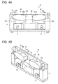
- Fig. 4A is a sectional view illustrating the configuration of the limited-area reflection type optical sensor 1A
- Fig. 4B is a perspective view illustrating a vertical section of the limited-area reflection type optical sensor 1A.
- Fig. 5 is a sectional view illustrating a configuration of an emitted light lens 12A.
- Fig. 6 is a perspective view illustrating configurations of an emitted light lens 12A and a reflected light lens 22.
- FIG. 7A is a view illustrating an optical path on a side having a curvature in a cylindrical lens
- Fig. 7B is a view illustrating an optical path on a side not having the curvature in the cylindrical lens.
- Fig. 8A is a sectional view illustrating a configuration of a modification of the limited-area reflection type optical sensor 1A
- Fig. 8B is a perspective view illustrating a vertical section of the modification of the limited-area reflection type optical sensor 1A.
- the limited-area reflection type optical sensor 1A includes a light emitter 10 and a light receiver 20, and the light emitter 10 and the light receiver 20 are accommodated in a case 2.
- the light emitter 10 includes an LED (Light Emitting Diode) 11 as the light emitting element and an emitted light lens 12A that is provided in a front surface of the LED 11.
- LED Light Emitting Diode
- the light receiver 20 includes a phototransistor 21 as the light receiving element and a reflected light lens 22 that is provided in a front surface of the phototransistor 21.
- the optical sensor 1A may include at least one of the emitted light lens 12A and the reflected light lens 22 as illustrated in Figs. 8A and 8B .
- the LED 11 may be used as the light emitting element and the phototransistor 21 may be used as the light receiving element.
- a laser diode may be used as the light emitting element and a photodiode may be used as the light receiving element.
- other kinds of light emitting elements except the LED and the laser diode and other kinds of light receiving elements except the phototransistor and the photodiode may be combined.
- front surfaces of the emitted light lens 12A and the reflected light lens 22 constitute a case opening 2a such that the emitted light and the reflected light can pass through the case 2.
- an intersection angle between optical axes of the emitted light and the reflected light is set such that the object sensing limited area S is irradiated with the light emitted from the light emitter 10, and such that the light receiver 20 can receive the light reflected from the object existing in the object sensing limited area S.
- the limited-area reflection type optical sensor 1A determines whether the object exists based on a light receiving level at the phototransistor 21, namely, a detection voltage. The determination whether the object exists is made by a determination unit on a printed board 3 that is of the determination section on which the LED 11 and the phototransistor 21 are mounted.
- the emitted light lens 12A that refracts the emitted light is provided in an optical path of the emitted light from the LED 11 to the object sensing limited area S.
- the emitted light lens 12A is one that has at least two different curvatures.
- an opposite-light-emitter-side surface 12b opposite to a light-emitter-side surface 12a of emitted light lens 12A constitutes a first curvature surface 12ba in which an opposite-light-receiver-side portion opposite to a light receiver side has a first curvature
- a light-receiver-side portion on the light receiver side with respect to the opposite-light-receiver-side portion constitutes a second curvature surface 12bb having a second curvature smaller than the first curvature of the first curvature surface 12ba.
- the first curvature of the first curvature surface 12ba may be at least double the second curvature of the second curvature surface 12bb.
- the emitted light lens 12A includes the first curvature surface 12ba and the second curvature surface 12bb in which the curvatures differ from each other.
- the emitted light lens may have at least three kinds of curvatures different from one another.
- the first curvature surface 12ba is constructed with an aspherical lens
- the second curvature surface 12bb is constructed with a cylindrical lens.
- the cylindrical lens has a shape in which a column is divided into two in an axial direction, or an axis of the cylindrical lens.
- FIG. 7B is a view illustrating an optical path of the emitted light through a side of the cylindrical lens without a curvature. Therefore, as illustrated in Fig. 7B , because there is no curvature provided in the optical path of the emitted light, the light passes directly through the side without the curvature in the same manner that the light passes through a plane parallel glass plate.
- FIG. 7B is a view illustrating an optical path of the emitted light through a side of the cylindrical lens without a curvature. Therefore, as illustrated in Fig. 7B , because there is no curvature provided in the optical path of the emitted light, the light passes directly through the side without the curvature in the same manner that the light passes through
- FIG. 7A illustrates an optical path of the emitted light through a side having a curvature in a cylindrical lens used in a second curvature surface of the emitted light lens and a fifth curvature surface of the reflected light lens.
- a semi-circular section of a second direction has the curvature, the light is bent to prevent diffusion of the light, and a light quantity can be increased in the object sensing limited area S.
- the first curvature surface 12ba constructed with the aspherical lens has the first curvature at a vertex of an aspherical lens surface
- the second curvature surface 12bb constructed with the cylindrical lens has a second curvature at a vertex of a cylindrical lens surface. That is, in the invention, the first curvature is larger than the second curvature under the definition that the vertex of the first curvature surface 12ba has the first curvature while the vertex of the second curvature surface 12bb has the second curvature.
- the emitted light lens 12A is formed by integrating the aspherical lens including the first curvature surface 12ba with the cylindrical lens including the second curvature surface 12bb.
- the first curvature surface 12ba and the second curvature surface 12bb may separately be formed.
- the reflected light lens 22 that refracts the reflected light is provided in the optical path of the reflected light from the object sensing limited area S to the phototransistor 21.
- the reflected light lens 22 has at least two different curvatures. Specifically, an opposite-light-receiver-side surface 22b opposite to a light-receiver-side surface 22a of the reflected light lens 22 constitutes a fourth curvature surface 22ba in which an opposite-light-emitter-side portion opposite to a light emitter side has a fourth curvature, and a light-emitter-side portion on the light emitter side with respect to the opposite-light-emitter-side portion constitutes a fifth curvature surface 22bb having a fifth curvature smaller than the fourth curvature of the fourth curvature surface 22ba.
- the reflected light lens 22 includes the fourth curvature surface 22ba and the fifth curvature surface 22bb in which the curvatures differ from each other. Alternatively, the reflected light lens may have at least three kinds of curvatures different from one another.
- the fourth curvature surface 22ba is constructed with the aspherical lens, while the fifth curvature surface 22bb is constructed with the cylindrical lens.
- the fourth curvature surface 22ba constructed with the aspherical lens has the fourth curvature at the vertex of the aspherical lens surface
- the fifth curvature surface 22bb constructed with the cylindrical lens has the fifth curvature at the vertex of the cylindrical lens surface. That is, in the invention, the fourth curvature is larger than the fifth curvature under the definition that the vertex of the fourth curvature surface 22ba has the fourth curvature while the vertex of the fifth curvature surface 22bb has the fifth curvature.
- the reflected light lens 22 is formed by integrating the aspherical lens including the fourth curvature surface 22ba with the cylindrical lens including the fifth curvature surface 22bb.
- the fourth curvature surface 22ba and the fifth curvature surface 22bb may separately be formed.
- Both the emitted light lens 12A and the reflected light lens 22 are provided in the limited-area reflection type optical sensor 1A.
- at least one of the emitted light lens 12A and the reflected light lens 22 may be provided as illustrated in Figs. 8A and 8B .
- At least one of the emitted light lens 12A and the reflected light lens 22 may be exchanged.
- Fig. 1 is a sectional view illustrating an optical path of emitted light L1 and an optical path of reflected light L2 in the limited-area reflection type optical sensor 1A and a detection state of an object M in the object sensing limited area S.
- Fig. 9 is a graph illustrating a relationship between a detection distance and detection performance of the object M in the phototransistor 21.
- the emitted light lens 12A is provided in the optical path of the light emitted from the LED 11 of the light emitter 10.
- the emitted light lens 12A includes the first curvature surface 12ba having the large curvature on the opposite-light-receiver side and the second curvature surface 12bb having the small curvature on the light receiver side. Accordingly, as illustrated in Fig.
- the emitted light L1 emitted from the LED 11 passes through the first curvature surface 12ba on the opposite-light-receiver side in the emitted light lens 12A
- the emitted light L1 has a high light flux density to reach a far distance side of the object sensing limited area S.
- the emitted light L1 passes through the second curvature surface 12bb on the light-receiver side in the emitted light lens 12A
- the emitted light L1 has a low light flux density to reach a near distance side of the object sensing limited area S.
- the reflected light lens 22 is provided in the optical path of the reflected light from the object sensing limited area S toward the phototransistor 21 of the light receiver 20.
- the reflected light lens 22 includes the fourth curvature surface 22ba having the large curvature on the opposite-light-emitter side and the fifth curvature surface 22bb having the small curvature on the light emitter side. Accordingly, as illustrated in Fig. 1 , the reflected light L2 from the far distance side of the object sensing limited area S passes through the fourth curvature surface 22ba on the opposite-light-emitter side of the reflected light lens 22 with the high light flux density. On the other hand, the reflected light L2 from the near distance side of the object sensing limited area S passes through the fifth curvature surface 22bb on the light emitter side of the emitted light lens 12A with the low light flux density.
- the phototransistor 21 can detect the reflected light L2 reflected from the object M.
- the emitted light lens 12A is provided in the optical path of the light emitted from the LED 11 of the light emitter 10 as illustrated in Fig. 1 .
- the emitted light lens 12A includes the first curvature surface 12ba having the large curvature on the opposite-light-receiver side and the second curvature surface 12bb having the small curvature on the light receiver side.
- the reflected light lens 22 is provided in the optical path of the reflected light from the object sensing limited area S toward the phototransistor 21 of the light receiver 20.
- the reflected light lens 22 includes the fourth curvature surface 22ba having the large curvature on the opposite-light-emitter side and the fifth curvature surface 22bb having the small curvature on the light receiver side. Accordingly, as illustrated in Fig. 9 , because the reflected light L2 reflected from the object M on the far distance side SL has the high light flux density, there is an acute fall in the detection performance of the phototransistor 21 in receiving reflected light from the object M on the far distance side SL. In the case that a threshold whether the object M exists on the far distance side SL is set, a boundary between an on area and an off area of the far distance side SL in the phototransistor 21 is clarified or clearly defined to be able to determine whether the object M exist.
- the light emitter 10 emits the emitted light L1 toward the object sensing limited area S, and the light receiver 20 receives the reflected light L2 from the object M existing in the object sensing limited area S.
- the emitted light L1 and the reflected light L2 from the object M are the single light beams.
- the emitted light lens 12A is provided in the optical path of the emitted light L1.
- the opposite-light-receiver-side portion opposite to the light receiver side constitutes the first curvature surface 12ba having the first curvature
- the light-receiver-side portion on the light receiver side with respect to the opposite-light-receiver-side portion constitutes the second curvature surface 12bb having the second curvature smaller than the first curvature.
- the quantity of light reflected from the object M can be increased, and the light receiver 20 receives the light quantity enough for the detection.
- the object M can be detected on the near distance side SS in the object sensing limited area S using the emitted light L1 passing through the second curvature surface 12bb having the small curvature in the light-receiver-side portion.
- the light receiver 20 receives the light quantity enough for the detection because of a short distance from the object M to the light receiver 20.
- the emitted light L1 passing through the second curvature surface 12bb having the small curvature has the low light flux density, so that the range can be spread in the direction of the near distance side SS.
- the configuration is simple because the emitted light lens 12A having the two curvatures different from each other is provided in order to spread the detection range.
- the limited-area reflection type optical sensor having the simple configuration can accurately detect the object, in which the distance to the surface to be measured changes, by spreading the detection range in a far-and-near direction, particularly on the near distance side.
- the above function can also be achieved by a configuration in which the reflected light lens 22 is provided instead of the emitted light lens 12A.
- the emitted light lens 12A provided in the optical path of the emitted light L1 the opposite-light-receiver-side portion opposite to the light receiver side constitutes the first curvature surface 12ba having the first curvature
- the light-receiver-side portion on the light receiver side with respect to the opposite-light-receiver-side portion constitutes the second curvature surface 12bb having the second curvature smaller than the first curvature.
- the opposite-light-emitter-side portion opposite to the light emitter side constitutes the fourth curvature surface 22ba having the fourth curvature
- the light-emitter-side portion on the light emitter side with respect to the opposite-light-emitter-side portion constitutes the fifth curvature surface 22bb having the fifth curvature smaller than the fourth curvature
- the light reflected from the object M on the far distance side SL in the object sensing limited area S is input to the light receiver 20 through the fourth curvature surface 22ba having the large curvature in the opposite-light-emitter-side portion of the reflected light lens 22.
- the reflected light L2 passing through the fourth curvature surface 22ba having the large curvature has the high light flux density, the quantity of light reflected from the object M can be increased, and the light receiver 20 receives the light quantity enough for the detection.
- the light reflected from the object on the near distance side in the object sensing limited area is input to the light receiver through the fifth curvature surface of the light-emitter-side having the small curvature in the reflected light lens.
- the light receiver receives the light quantity enough for the detection because of the short distance from the object to the light receiver.
- the configuration is also simple because the reflected light lens 22 having the two curvatures different from each other is provided in order to spread the detection range.
- the detection range in the far-and-near direction, particularly on the near distance side SS is spread by providing at least one of the emitted light lens 12A and the reflected light lens 22.
- the opposite-light-receiver-side portion opposite to the light receiver side constitutes the first curvature surface 12ba having the first curvature
- the light-receiver-side portion on the light receiver side with respect to the opposite-light-receiver-side portion constitutes the second curvature surface 12bb having the second curvature smaller than the first curvature.
- the opposite-light-emitter-side portion opposite to the light emitter side constitutes the fourth curvature surface 22ba having the fourth curvature
- the light-emitter-side portion on the light emitter side with respect to the opposite-light-emitter-side portion constitutes the fifth curvature surface 22bb having the fifth curvature smaller than the fourth curvature.
- the first curvature of the first curvature surface 12ba in the emitted light lens 12A is at least double the second curvature of the second curvature surface 12bb.
- the emitted light L1 passing through the first curvature surface 12ba has the dense light flux, and the object M on the far distance side SL in the object sensing limited area S can be detected compared with the emitted light L1 passing through the second curvature surface 12bb.
- a threshold for the detection is easy to set.
- the fourth curvature of the fourth curvature surface 22ba in the reflected light lens 22 is at least double the fifth curvature of the fifth curvature surface 22bb. Therefore, the reflected light L2 passing through the fourth curvature surface 22ba has the dense light flux compared with the reflected light L2 passing through the fifth curvature surface 22bb, and the object M on the far distance side SL in the object sensing limited area S can be detected.
- a threshold for the detection is easy to set.
- the determination unit on the printed board 3 that is of the determination section determining whether the object M exists in the object sensing limited area S based on the light receiving level at the light receiver 20 is provided in the limited-area reflection type optical sensor 1A. Therefore, the determination unit on the printed board 3 can determine whether the object M exists in the object sensing limited area S based on the light receiving level at the light receiver 20. The determination that the object does not exist in the object sensing limited area S is made when the light receiving level at the light receiver 20 is zero, and the determination that the object M exists in the object sensing limited area S is made when the light receiving level at the light receiver 20 is greater than or equal to a predetermined detection value.
- At least one of the condition that at least one of the first curvature and the second curvature can be changed to a different curvature in the emitted light lens 12A and the condition that at least one of the fourth curvature and the fifth curvature can be changed to a different curvature in the reflected light lens 22 is satisfied in the limited-area reflection type optical sensor 1A.
- the object sensing limited area S may be changed easily.
- At least one of the condition that the first curvature surface 12ba and the second curvature surface 12bb are integrally formed in the emitted light lens 12A and the condition that the fourth curvature surface 22ba and the fifth curvature surface 22bb are integrally formed in the reflected light lens 22 is satisfied in the limited-area reflection type optical sensor 1A.
- Position accuracy can be improved compared with the case that the two different curvatures are separated from each other, and a measure against stray light can be taken in the case that the two different curvatures are separated from each other. Additionally, the emitted light lens 12A or the reflected light lens 22 can separately be exchanged.
- the second curvature surface 12bb of the emitted light lens 12A constitutes a part of the cylindrical lens.
- the cylindrical lens is the semi-columnar lens. Therefore, although the light passes directly through the section having no curvature, the light is bent in a semi-circular section having the curvature, and the diffusion of the light can be prevented to increase the light quantity in the object sensing limited area S.
- the second curvature surface 12bb having the second curvature smaller than the first curvature may be produced in the light-receiver-side portion on the light receiver side with respect to the opposite-light-receiver-side portion.
- first curvature surface 12ba and the second curvature surface 12bb are separately formed
- a commercially available cylindrical lens can be used as the second curvature surface 12bb having the second curvature smaller than the first curvature in the light-receiver-side portion on the light receiver side with respect to the opposite-light-receiver-side portion in the opposite-light-emitter-side surface 12b of the emitted light lens 12A.
- cost reduction can be achieved compared with the case that the second curvature surface 12bb of the emitted light lens 12 is separately produced.
- the fifth curvature surface 22bb of the reflected light lens 22 constitutes a part of the cylindrical lens.
- the cylindrical lens is the semi-columnar lens. Therefore, although the light passes directly through the section having no curvature, the light is bent in a semi-circular section having the curvature, and the diffusion of the light can be prevented to increase the light quantity in the object sensing limited area S.
- the fifth curvature surface 22bb having the fifth curvature smaller than the fourth curvature may be produced in the light-emitter-side portion on the light emitter side with respect to the opposite-light-emitter-side portion.
- the fourth curvature surface 22ba and the fifth curvature surface 22bb are separately formed, a commercially available cylindrical lens can be used as the fifth curvature surface 22bb having the fifth curvature smaller than the fourth curvature in the light-emitter-side portion on the light emitter side with respect to the opposite-light-emitter-side portion in the opposite-light-receiver-side surface 22b of the reflected light lens 22.
- the cost reduction can be achieved compared with the case that the fifth curvature surface 22bb of the reflected light lens 22 is separately produced.
- an electronic device may include the limited-area reflection type optical sensor 1 A.
- the limited-area reflection type optical sensor 1A having the simple configuration can accurately detect the object M, in which the distance to the surface to be measured changes, by increasing the detection range.
- a limited-area reflection type optical sensor 1 B differs from the limited-area reflection type optical sensor 1A in that the limited-area reflection type optical sensor 1 B includes an integrated emitted light/reflected light lens 30 to integrally form the emitted light lens 12A and the reflected light lens 22.
- FIG. 10 is a perspective view illustrating the configuration of the limited-area reflection type optical sensor 1 B.
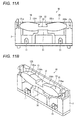
- Fig. 11A is a sectional view illustrating the configuration of the limited-area reflection type optical sensor 1 B, and Fig. 11B is a perspective view illustrating a vertical section of the limited-area reflection type optical sensor 1 B.
- Fig. 12 is a perspective view illustrating a configuration of the integrated emitted light/reflected light lens 30 provided in the light emitter 10 and the light receiver 20 of the limited-area reflection type optical sensor 1 B.
- the limited-area reflection type optical sensor 1 B includes the integrated emitted light/reflected light lens 30.
- the integrated emitted light/reflected light lens 30 As illustrated in Fig. 10 , the limited-area reflection type optical sensor 1 B includes the integrated emitted light/reflected light lens 30.
- a coupling unit 31 is provided between the emitted light lens 12A and the reflected light lens 22, and the emitted light lens 12A and the reflected light lens 22 are integrally coupled to each other by the coupling unit 31.
- the first curvature surface 12ba in the emitted light lens 12A is constructed with the aspherical lens similarly to the embodiment of FIG. 3 .
- the second curvature surface 12bb is constructed with the cylindrical lens.
- the fourth curvature surface 22ba in the reflected light lens 22 is constructed with the aspherical lens.
- the fifth curvature surface 22bb is constructed with the cylindrical lens.
- the emitted light lens 12A and the reflected light lens 22 are constructed with the integrated emitted light/reflected light lens 30 in which the emitted light lens 12A and the reflected light lens 22 are integrally formed. Therefore, the number of components can further be decreased. The position accuracy can be improved compared with the case that the emitted light lens 12A and the reflected light lens 22 are separated from each other. Additionally, the integrated emitted light/reflected light lens 30 is easy to exchange.
- the optical axis of the emitted light of the LED 11 is aligned with the center axis of the emitted light lens 12A.
- the light receiving axis of the phototransistor 21 is aligned with the center axis of the reflected light lens 22.
- a limited-area reflection type optical sensor 1C differs from the limited-area reflection type optical sensors 1A and 1 B in that the optical axis of the emitted light of the LED 11 is arranged on the opposite-light-receiver side with respect to the center axis of the emitted light lens 12A, and that the light receiving axis of the phototransistor 21 is arranged on the opposite-light-emitter side with respect to the center axis of the reflected light lens 22.
- Fig. 13 is a front view illustrating the configuration of the limited-area reflection type optical sensor 1C.
- the light emitter 10 includes the LED 11 that is of the light emitting element emitting the emitted light L1, and the LED 11 is arranged such that the optical axis of the emitted light L1 emitted from the LED 11 is located on the opposite-light-receiver side with respect to the center axis of the emitted light lens 12A.
- the light receiver 20 includes the phototransistor 21 that is of the light receiving element receiving the reflected light L2, and the phototransistor 21 is arranged such that the optical axis of the reflected light L2 in the phototransistor 21 is located on the opposite-light-emitter side with respect to the center axis of the reflected light lens 22.
- the spread of the light flux is eliminated on the far distance side, and only the portion having the high light flux density can be limited as the object sensing limited area S.
- Each of the limited-area reflection type optical sensor 1A, the limited-area reflection type optical sensor 1 B, and the limited-area reflection type optical sensor 1C includes one phototransistor 21.
- a limited-area reflection type optical sensor 1 D differs from the limited-area reflection type optical sensors 1A, 1 B, and 1C in that the limited-area reflection type optical sensor 1 D includes plural phototransistors 21.
- FIGS. 14A, 14B, and 14C are front views illustrating the light receiving states of plural phototransistors 21 a, 21 b, and 21 c in the limited-area reflection type optical sensor 1 D.
- the limited-area reflection type optical sensor 1 D includes three phototransistor 21 a, 21 b, and 21 c that are of the light receiving element.
- the phototransistor 21 a can receive the light on the near distance side SS nearest the limited-area reflection type optical sensor 1 D in the object sensing limited area S.
- the phototransistor 21 b can receive the light on an intermediate distance side SM located at an intermediate position from the limited-area reflection type optical sensor 1 D in the object sensing limited area S.
- the phototransistor 21 c can receive the light on the far distance side SL farthest from the limited-area reflection type optical sensor 1 D in the object sensing limited area S.
- the determination that the object M exists at the position on the near distance side SS nearest the limited-area reflection type optical sensor 1 D in the object sensing limited area S can be made in the case that the phototransistor 21 a senses the signal.
- the determination that the object M exists at the position on the intermediate distance side SM in the object sensing limited area S can be made in the case that the phototransistor 21 b senses the signal.
- the determination that the object M exists at the position on the far distance side SL farthest from the limited-area reflection type optical sensor 1 D in the object sensing limited area S can be made in the case that the phototransistor 21 c senses the signal.
- the limited-area reflection type optical sensor 1 D can be used as a displacement sensor that determines the position of the object M.
- an object moving direction detection section may be provided in the limited-area reflection type optical sensor 1 D.
- the object moving direction detection section determines whether the object M approaches or recedes by detecting the light receiving levels at the phototransistors 21 a, 21 b, and 21 c that is of the light receiving element, namely, the change in detection voltage at the phototransistors 21 a, 21 b, and 21c.
- the object moving direction detection section determines whether the object approaches or recedes can be detected based on the change of the light receiving level at the phototransistors 21 a, 21 b, and 21 c.
- the limited-area reflection type optical sensor 1 D may include a moving speed calculation section that calculates the approaching speed or the receding speed of the object M based on the light receiving levels of the phototransistors 21 a, 21 b, and 21 c, namely, a time change in detection voltage.
- the approaching speed or the receding speed of the object M can be calculated based on the time change of the light receiving level at the phototransistors 21 a, 21 b, and 21 c.
- the opposite-light-emitter-side surface 12b includes the first curvature surface 12ba having the first curvature with large curvature on the opposite-light-receiver side and the second curvature surface 12bb having the second curvature with small curvature on the light receiver side in the emitted light lens 12A and the integrated emitted light/reflected light lens 30, in which the two curvatures are different from each other.
- a limited-area reflection type optical sensor 1 E differs from the limited-area reflection type optical sensors 1A, 1 B, 1C, and 1 D in that the opposite-light-emitter-side surface 12b further includes a third curvature surface having a third curvature larger than the second curvature on the light receiver side with respect to the second curvature surface 12bb having the second curvature.
- Fig. 15A is a sectional view illustrating the configuration of an emitted light lens 12B in the limited-area reflection type optical sensor 1 E
- Fig. 15B is a waveform chart illustrating the detection signal in the object sensing limited area S.
- the light receiver side with respect to the second curvature surface 12bb constitutes a third curvature surface 12bc having the third curvature larger than the second curvature of the second curvature surface 12bb in the opposite-light-emitter-side surface 12b of the emitted light lens 12B.
- the third curvature of the third curvature surface 12bc is at least double the second curvature of the second curvature surface 12bb.
- the first curvature surface 12ba is identical to the first curvature surface 12ba of the emitted light lens 12A of FIGS. 3 , 10 , and 13 .
- the opposite-light-receiver-side portion constitutes the first curvature surface 12ba having the large curvature
- the light flux density of the emitted light L1 on the most opposite-light-receiver side increases in the emitted light L1 passing through the emitted light lens 12B, which allows an acute light intensity distribution of the emitted light L1 to be formed on the most opposite-light-receiver side.
- the threshold may be set in order to determine whether the object M exists.
- the light receiver side (the right side in Fig. 15A ) from the second curvature surface 12bb constitutes the third curvature surface 12bc having the third curvature larger than the second curvature of the second curvature surface 12bb in the opposite-light-emitter-side surface 12b of the emitted light lens 12B.
- the most light-receiver-side portion constitutes the third curvature surface 12bc having the third curvature larger than the second curvature of the second curvature surface 12bb, which allows the acute light intensity distribution of the emitted light L1 to be formed on the most light receiver side.
- the threshold may be set in order to determine whether the object M exists.
- the threshold may be set in order to determine whether the object M exists with respect to both the far distance side SL and the near distance side SS in the object sensing limited area S.
- the embodiment is described for the emitted light lens 12B.
- the reflected light lens 22 may have the similar configuration.
- the light emitter side with respect to the fifth curvature surface 22bb constitutes a sixth curvature surface having a sixth curvature larger than the fifth curvature of the fifth curvature surface 22bb in the opposite-light-receiver-side surface 22b of the reflected light lens 22.
- the sixth curvature of the sixth curvature surface in the reflected light lens 22 is at least double the fifth curvature of the fifth curvature surface 22bb.
- the threshold may be set in order to determine whether the object exists with respect to both the far distance side SL and the near distance side SS in the object sensing limited area S.
- the configuration including the third curvature surface 12bc and the sixth curvature can also be applied to the integrated emitted light/reflected light lens 30 of FIG. 10 .
- the object on the far distance side in the object sensing limited area may be detected using the emitted light passing through the first curvature surface having the large curvature in the opposite-light-receiver-side portion.
- the emitted light passing through the first curvature surface having the large curvature has the high light flux density, a quantity of light reflected from the object can be increased, and the light receiver receives the light quantity enough for the detection.
- the object can be detected on the near distance side in the object sensing limited area using the emitted light passing through the second curvature surface having the small curvature in the light-receiver-side portion.
- the light receiver receives the light quantity enough for the detection because of a short distance from the object to the light receiver.
- the emitted light passing through the second curvature surface having the small curvature has the low light flux density, so that the range can be spread in the direction of the near distance side.
- the configuration is simple because the emitted light lens having the two curvatures different from each other is provided in order to spread the detection range.
- the limited-area reflection type optical sensor having the simple configuration can accurately detect the object, in which the distance to the surface to be measured changes, by spreading the detection range in a far-and-near direction, particularly on the near distance side.
- the above function can also be achieved by a configuration in which the reflected light lens is provided instead of the emitted light lens.
- the opposite-light-receiver-side portion opposite to the light receiver side constitutes the first curvature surface having the first curvature
- the light-receiver-side portion on the light receiver side with respect to the opposite-light-receiver-side portion constitutes the second curvature surface having the second curvature smaller than the first curvature.
- the opposite-light-emitter-side portion opposite to the light emitter side constitutes the fourth curvature surface having the fourth curvature
- the light-emitter-side portion on the light emitter side with respect to the opposite-light-emitter-side portion constitutes the fifth curvature surface having the fifth curvature smaller than the fourth curvature
- the light reflected from the object on the far distance side in the object sensing limited area is input to the light receiver through the fourth curvature surface having the large curvature in the opposite-light-emitter-side portion of the reflected light lens.
- the emitted light passing through the fourth curvature surface having the large curvature has the high light flux density, the quantity of light reflected from the object can be increased, and the light receiver receives the light quantity enough for the detection.
- the light reflected from the object on the near distance side in the object sensing limited area is input to the light receiver through the fifth curvature surface having the small curvature in the reflected light lens.
- the light receiver receives the light quantity enough for the detection because of the short distance from the object to the light receiver.
- the detection range is spread in the far-and-near direction like the case that the emitted light lens having the two curvatures different from each other is provided in the optical path of the emitted light.
- the configuration is also simple because the reflected light lens having the two curvatures different from each other is provided in order to spread the detection range.
- the detection range in the far-and-near direction, particularly on the near distance side is spread by providing at least one of the emitted light lens and the reflected light lens.
- the opposite-light-receiver-side portion opposite to the light receiver side constitutes the first curvature surface having the first curvature
- the light-receiver-side portion on the light receiver side with respect to the opposite-light-receiver-side portion constitutes the second curvature surface having the second curvature smaller than the first curvature.
- the opposite-light-emitter-side portion opposite to the light emitter side constitutes the fourth curvature surface having the fourth curvature
- the light-emitter-side portion on the light emitter side with respect to the opposite-light-emitter-side portion constitutes the fifth curvature surface having the fifth curvature smaller than the fourth curvature.
- the limited-area reflection type optical sensor may include a determination section configured to determine whether the object exists in the object sensing limited area based on a light receiving level at the light receiver.
- the determination section can determine whether the object exists in the object sensing limited area based on the light receiving level at the light receiver.
- the determination that the object does not exist in the object sensing limited area is made when the light receiving level is zero at the light receiver, and the determination that the object exists in the object sensing limited area is made when the light receiving level is greater than or equal to a predetermined detection value at the light receiver.
- the limited-area reflection type optical sensor preferably at least one of a condition that at least one of the first curvature and the second curvature can be changed to a different curvature in the emitted light lens and a condition that at least one of the fourth curvature and the fifth curvature can be changed to a different curvature in the reflected light lens is satisfied.
- At least one of the emitted light lens and the reflected light lens can be exchanged to one having the different curvature.
- the object sensing limited area may be changed easily.
- the limited-area reflection type optical sensor preferably at least one of a condition that the first curvature surface and the second curvature surface are integrally formed in the emitted light lens and a condition that the fourth curvature surface and the fifth curvature surface are integrally formed in the reflected light lens is satisfied.
- Position accuracy can be improved compared with the case that the two different curvatures are separated from each other, and a measure against stray light can be taken in the case that the two different curvatures are separated from each other. Additionally, the emitted light lens or the reflected light lens can separately be exchanged.
- the emitted light lens and the reflected light lens are integrally formed.
- the position accuracy can be improved compared with the case that the emitted light lens and the reflected light lens are separated from each other.
- the integrated lens is easy to exchange.
- the light emitter includes a light emitting element configured to emit the emitted light
- the light emitting element is arranged such that an optical axis of the emitted light emitted from the light emitting element is located on the opposite-light-receiver side with respect to a center axis of the emitted light lens
- the light receiver includes a light receiving element configured to receive the reflected light
- the light receiving element is arranged such that an optical axis of the reflected light in the light receiving element is located on the opposite-light-emitter side with respect to a center axis of the reflected light lens.
- the spread of the light flux is eliminated on the far distance side, and only the portion having the high light flux density can be limited as the object sensing limited area.
- plural light receiving elements configured to receive the reflected light reflected from the object from plural directions are provided in the light receiver.
- the limited-area reflection type optical sensor can be used as a displacement sensor that determines the position of the object.
- a third curvature surface having a third curvature larger than the second curvature of the second curvature surface is formed on the light receiver side with respect to the second curvature surface in the emitted light lens.
- the most opposite-light-receiver-side portion has a first curvature having the large curvature, the light flux density of the emitted light on the most opposite-light-receiver side increases in the emitted light passing through the emitted light lens, which allows an acute light intensity distribution of the emitted light to be formed on the most opposite-light-receiver side.
- a threshold may be set in order to determine whether the object exists.
- the third curvature surface having the third curvature larger than the second curvature of the second curvature surface is formed on the light receiver side with respect to the second curvature surface in the emitted light lens. That is, in the emitted light lens, the most light-receiver-side portion constitutes the third curvature surface having the third curvature larger than the second curvature, which allows an acute light intensity distribution of the emitted light to be formed on the most light receiver side.
- a threshold may be set in order to determine whether the object exists.
- the threshold may be set in order to determine whether the object exists with respect to both the far distance side and the near distance side in the object sensing limited area.
- the second curvature surface of the emitted light lens constitutes a part of a cylindrical lens.
- the cylindrical lens is the semi-columnar lens. Therefore, although the light passes directly through the section having no curvature, the light is bent in a semi-circular section having the curvature, and diffusion of the light can be prevented to increase the light quantity in the object sensing limited area.
- the second curvature surface having the second curvature smaller than the first curvature may be produced in the light-receiver-side portion on the light receiver side with respect to the opposite-light-receiver-side portion.
- a commercially available cylindrical lens can be used as the second curvature surface in the case that the first curvature surface and the second curvature surface are separately formed. As a result, cost reduction can be achieved compared with the case that the second curvature surface of the emitted light lens is separately produced.
- a sixth curvature surface having a sixth curvature larger than the fifth curvature of the fifth curvature surface is formed on the light emitter side with respect to the fifth curvature surface in the reflected light lens.
- the most opposite-light-emitter-side portion has a fourth curvature having the large curvature, the light flux density of the reflected light on the most opposite-light-emitter side increases in the reflected light passing through the fourth curvature surface of the reflected light lens, which allows the acute light intensity distribution of the reflected light to be formed on the most opposite-light-emitter side.
- a threshold may be set in order to determine whether the object exists.
- the sixth curvature surface having the sixth curvature larger than the fifth curvature of the fifth curvature surface is formed on the light emitter side with respect to the fifth curvature surface in the reflected light lens. That is, in the reflected light lens, the most light-emitter-side portion constitutes the sixth curvature surface having the sixth curvature larger than the fifth curvature, which allows the acute light intensity distribution of the reflected light to be formed on the most light emitter side.
- a threshold may be set in order to determine whether the object exists.
- the threshold may be set in order to determine whether the object exists with respect to both the far distance side and the near distance side in the object sensing limited area.
- the fifth curvature surface of the reflected light lens constitutes a part of a cylindrical lens.
- the cylindrical lens is the semi-columnar lens. Therefore, although the light passes directly through the section having no curvature, the light is bent in a semi-circular section having the curvature, and diffusion of the light can be prevented to increase the light quantity in the object sensing limited area.
- the fifth curvature surface having the fifth curvature smaller than the fourth curvature may be produced in the light-emitter-side portion on the light emitter side with respect to the opposite-light-emitter-side portion.
- a commercially available cylindrical lens can be used as the fifth curvature surface in the case that the fourth curvature surface and the fifth curvature surface are separately formed. As a result, the cost reduction can be achieved compared with the case that the fifth curvature surface of the reflected light lens is separately produced.
- a threshold used to determine whether the object exists can easily be set.
- an electronic device includes the above limited-area reflection type optical sensor.
- the electronic device including the limited-area reflection type optical sensor can be provided.
- the limited-area reflection type optical sensor having the simple configuration can accurately detect the object, in which the distance to the surface to be measured changes, by spreading the detection range.
- the simple-configuration limited-area reflection type optical sensor that can accurately detect the object, in which the distance to the surface to be measured changes, by spreading the detection range and the electronic device can advantageously be provided.
- the invention can be applied to the limited-area reflection type optical sensor in which the object detection area is limited.
- the limited-area reflection type optical sensor can be applied to electronic devices of mobile robots such as a robot cleaner, a robotic wheelchair, and a security watching robot.
- the limited-area reflection type optical sensor can also be applied to a board sensing conveyer (board sensing), a food packing machine, an FPC production apparatus (transparent film sensing), and a general conveying apparatus.
Landscapes
- Physics & Mathematics (AREA)
- Engineering & Computer Science (AREA)
- General Physics & Mathematics (AREA)
- Electromagnetism (AREA)
- Computer Networks & Wireless Communication (AREA)
- Radar, Positioning & Navigation (AREA)
- Remote Sensing (AREA)
- General Life Sciences & Earth Sciences (AREA)
- Life Sciences & Earth Sciences (AREA)
- Geophysics (AREA)
- Geophysics And Detection Of Objects (AREA)
- Switches Operated By Changes In Physical Conditions (AREA)
- Photometry And Measurement Of Optical Pulse Characteristics (AREA)
- Optical Radar Systems And Details Thereof (AREA)
- Investigating Or Analysing Materials By Optical Means (AREA)
- Length Measuring Devices By Optical Means (AREA)
- Photo Coupler, Interrupter, Optical-To-Optical Conversion Devices (AREA)
Applications Claiming Priority (1)
| Application Number | Priority Date | Filing Date | Title |
|---|---|---|---|
| JP2013218668A JP6303388B2 (ja) | 2013-10-21 | 2013-10-21 | 限定領域反射型光学センサ及び電子機器 |
Publications (3)
| Publication Number | Publication Date |
|---|---|
| EP2866059A2 true EP2866059A2 (fr) | 2015-04-29 |
| EP2866059A3 EP2866059A3 (fr) | 2015-06-03 |
| EP2866059B1 EP2866059B1 (fr) | 2022-05-11 |
Family
ID=52469564
Family Applications (1)
| Application Number | Title | Priority Date | Filing Date |
|---|---|---|---|
| EP14188307.4A Active EP2866059B1 (fr) | 2013-10-21 | 2014-10-09 | Capteur optique de type à réflexion à zone restreinte et dispositif électronique |
Country Status (5)
| Country | Link |
|---|---|
| US (1) | US9519059B2 (fr) |
| EP (1) | EP2866059B1 (fr) |
| JP (1) | JP6303388B2 (fr) |
| KR (1) | KR101640989B1 (fr) |
| CN (1) | CN104569996B (fr) |
Cited By (1)
| Publication number | Priority date | Publication date | Assignee | Title |
|---|---|---|---|---|
| CN114296088A (zh) * | 2021-12-09 | 2022-04-08 | 广东烨嘉光电科技股份有限公司 | 一种近距离探测器 |
Families Citing this family (10)
| Publication number | Priority date | Publication date | Assignee | Title |
|---|---|---|---|---|
| JP6614909B2 (ja) | 2015-10-15 | 2019-12-04 | アズビル株式会社 | 光電センサ |
| CN107064906B (zh) * | 2016-12-12 | 2023-07-14 | 东莞市美光达光学科技有限公司 | 一种测距透镜模组及激光测距装置 |
| JP7026912B2 (ja) * | 2017-02-06 | 2022-03-01 | 大阪瓦斯株式会社 | ガスコンロ |
| US11453123B2 (en) * | 2017-12-27 | 2022-09-27 | Stmicroelectronics, Inc. | Robotic device with time-of-flight proximity sensing system |
| JP6947065B2 (ja) * | 2018-02-06 | 2021-10-13 | オムロン株式会社 | 限定反射型センサ |
| JP6904285B2 (ja) | 2018-03-13 | 2021-07-14 | オムロン株式会社 | 限定反射型センサ |
| JP7003858B2 (ja) * | 2018-07-13 | 2022-01-21 | オムロン株式会社 | 光センサ |
| CN109461662B (zh) * | 2018-09-28 | 2020-06-02 | 深圳赛意法微电子有限公司 | 多点近距离感应器的封装方法 |
| KR102121398B1 (ko) * | 2018-10-29 | 2020-06-10 | 니덱모빌리티코리아 주식회사 | 비구면렌즈로 구성된 차량용 레인센서 |
| JP7354716B2 (ja) * | 2019-09-20 | 2023-10-03 | 株式会社デンソーウェーブ | レーザレーダ装置及びレーザレーダ装置用レンズ |
Citations (1)
| Publication number | Priority date | Publication date | Assignee | Title |
|---|---|---|---|---|
| JPH06241783A (ja) | 1993-02-18 | 1994-09-02 | Rohm Co Ltd | 三角測距式光電センサ |
Family Cites Families (14)
| Publication number | Priority date | Publication date | Assignee | Title |
|---|---|---|---|---|
| JPS5992372A (ja) * | 1982-11-18 | 1984-05-28 | Nippon Soken Inc | 車両用障害物検知装置 |
| JPH02114414A (ja) * | 1988-10-24 | 1990-04-26 | Yamatake Honeywell Co Ltd | 反射形光電スイツチ用レンズユニツト |
| JP2855744B2 (ja) * | 1989-02-20 | 1999-02-10 | オムロン株式会社 | 反射形光電スイッチ |
| DE4125479C3 (de) * | 1991-08-01 | 2002-01-10 | Leuze Electronic Gmbh & Co | Reflexionslichttaster |
| JP3350826B2 (ja) * | 1993-06-25 | 2002-11-25 | オムロン株式会社 | 限定反射型光電センサ |
| JP2001267625A (ja) * | 2000-03-16 | 2001-09-28 | Keyence Corp | 限定反射型光電スイッチ |
| JP4357731B2 (ja) * | 2000-10-31 | 2009-11-04 | サンクス株式会社 | 反射型光電センサの検出ヘッド |
| JP2003279405A (ja) * | 2002-03-20 | 2003-10-02 | Kyocera Corp | 限定反射型光電センサ |
| EP1408343A1 (fr) * | 2003-02-14 | 2004-04-14 | Siemens Aktiengesellschaft | Fenêtre pour capteur de proximité, capteur de proximité, terminale mobile, et méthode de détection de présence d'un objet |
| JP4887057B2 (ja) * | 2006-02-17 | 2012-02-29 | 株式会社キーエンス | 光電センサ |
| DE102007025987A1 (de) * | 2007-06-04 | 2009-01-08 | Trw Automotive Electronics & Components Gmbh | Optische Sensorvorrichtung zur Erfassung einer Benetzung |
| KR101406929B1 (ko) * | 2011-10-14 | 2014-06-12 | 오므론 가부시키가이샤 | 광전 센서 |
| JP6003121B2 (ja) * | 2012-03-15 | 2016-10-05 | オムロン株式会社 | 反射型光電センサ |
| JP2016075564A (ja) * | 2014-10-06 | 2016-05-12 | 株式会社リコー | 投射光学系、物体検出装置 |
-
2013
- 2013-10-21 JP JP2013218668A patent/JP6303388B2/ja active Active
-
2014
- 2014-09-26 KR KR1020140128835A patent/KR101640989B1/ko active Active
- 2014-09-30 CN CN201410519995.2A patent/CN104569996B/zh active Active
- 2014-10-06 US US14/507,289 patent/US9519059B2/en active Active
- 2014-10-09 EP EP14188307.4A patent/EP2866059B1/fr active Active
Patent Citations (1)
| Publication number | Priority date | Publication date | Assignee | Title |
|---|---|---|---|---|
| JPH06241783A (ja) | 1993-02-18 | 1994-09-02 | Rohm Co Ltd | 三角測距式光電センサ |
Cited By (1)
| Publication number | Priority date | Publication date | Assignee | Title |
|---|---|---|---|---|
| CN114296088A (zh) * | 2021-12-09 | 2022-04-08 | 广东烨嘉光电科技股份有限公司 | 一种近距离探测器 |
Also Published As
| Publication number | Publication date |
|---|---|
| KR101640989B1 (ko) | 2016-07-19 |
| KR20150045887A (ko) | 2015-04-29 |
| EP2866059B1 (fr) | 2022-05-11 |
| CN104569996B (zh) | 2017-10-03 |
| EP2866059A3 (fr) | 2015-06-03 |
| CN104569996A (zh) | 2015-04-29 |
| US9519059B2 (en) | 2016-12-13 |
| JP2015081801A (ja) | 2015-04-27 |
| US20150108332A1 (en) | 2015-04-23 |
| JP6303388B2 (ja) | 2018-04-04 |
Similar Documents
| Publication | Publication Date | Title |
|---|---|---|
| US9519059B2 (en) | Limited-area reflection type optical sensor and electronic device | |
| JP5949931B2 (ja) | 光センサ | |
| US7984561B2 (en) | Device for determining dimension of a workpiece | |
| CN104062690A (zh) | 有限区域反射型光电传感器 | |
| US11550161B2 (en) | Illumination system having different light sources adapt to different work surfaces | |
| CN105264328A (zh) | 用于无接触地光学确定穿透位置的测量框架及配属的测量方法 | |
| CN100580369C (zh) | 距离测量传感器及装备有该距离测量传感器的电子设备 | |
| FI59300C (fi) | Foerfarande och anordning vid kontaktfri maetning | |
| JP4584065B2 (ja) | エレベータの乗客検出装置 | |
| JP2011141142A (ja) | 測距センサおよび電子機器 | |
| JP2007031103A5 (fr) | ||
| GB2446961A (en) | Pointing device | |
| SE1250316A1 (sv) | Optisk sensor | |
| CN102063228B (zh) | 光学侦测系统及应用该光学侦测系统的触摸屏 | |
| EP3688484B1 (fr) | Dispositif de mesure de distance par les temps de vol | |
| JP6414351B2 (ja) | 限定領域反射型光学センサ及び電子機器 | |
| US11886649B2 (en) | Optical navigation device | |
| KR101324627B1 (ko) | 3차원 공간인식 센서모듈 | |
| US7368704B2 (en) | Self-contained fork sensor having a wide effective beam | |
| JP7329943B2 (ja) | 検出装置及び移動装置 | |
| KR101236200B1 (ko) | 다중 반사를 이용한 터치스크린 장치 | |
| JP4034328B2 (ja) | 発光検出装置および座標検出装置 | |
| KR20160064628A (ko) | Pcb 위치 감지 장치 | |
| KR101243614B1 (ko) | 광학적 터치스크린 장치 | |
| JP2023183315A (ja) | 発光装置、光測距装置、及び、画像形成装置 |
Legal Events
| Date | Code | Title | Description |
|---|---|---|---|
| PUAI | Public reference made under article 153(3) epc to a published international application that has entered the european phase |
Free format text: ORIGINAL CODE: 0009012 |
|
| 17P | Request for examination filed |
Effective date: 20141009 |
|
| AK | Designated contracting states |
Kind code of ref document: A2 Designated state(s): AL AT BE BG CH CY CZ DE DK EE ES FI FR GB GR HR HU IE IS IT LI LT LU LV MC MK MT NL NO PL PT RO RS SE SI SK SM TR |
|
| AX | Request for extension of the european patent |
Extension state: BA ME |
|
| PUAL | Search report despatched |
Free format text: ORIGINAL CODE: 0009013 |
|
| AK | Designated contracting states |
Kind code of ref document: A3 Designated state(s): AL AT BE BG CH CY CZ DE DK EE ES FI FR GB GR HR HU IE IS IT LI LT LU LV MC MK MT NL NO PL PT RO RS SE SI SK SM TR |
|
| AX | Request for extension of the european patent |
Extension state: BA ME |
|
| RIC1 | Information provided on ipc code assigned before grant |
Ipc: G01V 8/00 20060101ALI20150429BHEP Ipc: G01S 7/481 20060101AFI20150429BHEP Ipc: G01S 17/02 20060101ALI20150429BHEP Ipc: G01S 17/08 20060101ALI20150429BHEP Ipc: G01V 8/12 20060101ALI20150429BHEP |
|
| R17P | Request for examination filed (corrected) |
Effective date: 20151203 |
|
| RBV | Designated contracting states (corrected) |
Designated state(s): AL AT BE BG CH CY CZ DE DK EE ES FI FR GB GR HR HU IE IS IT LI LT LU LV MC MK MT NL NO PL PT RO RS SE SI SK SM TR |
|
| STAA | Information on the status of an ep patent application or granted ep patent |
Free format text: STATUS: EXAMINATION IS IN PROGRESS |
|
| 17Q | First examination report despatched |
Effective date: 20170919 |
|
| REG | Reference to a national code |
Ref country code: DE Ref legal event code: R079 Ref document number: 602014083671 Country of ref document: DE Free format text: PREVIOUS MAIN CLASS: G01V0008000000 Ipc: G01S0007481000 |
|
| RIC1 | Information provided on ipc code assigned before grant |
Ipc: G01S 17/04 20200101ALI20210901BHEP Ipc: G01V 8/12 20060101ALI20210901BHEP Ipc: G01S 17/02 20200101ALI20210901BHEP Ipc: G01V 8/00 20060101ALI20210901BHEP Ipc: G01S 17/08 20060101ALI20210901BHEP Ipc: G01S 7/481 20060101AFI20210901BHEP |
|
| GRAP | Despatch of communication of intention to grant a patent |
Free format text: ORIGINAL CODE: EPIDOSNIGR1 |
|
| STAA | Information on the status of an ep patent application or granted ep patent |
Free format text: STATUS: GRANT OF PATENT IS INTENDED |
|
| INTG | Intention to grant announced |
Effective date: 20211027 |
|
| GRAJ | Information related to disapproval of communication of intention to grant by the applicant or resumption of examination proceedings by the epo deleted |
Free format text: ORIGINAL CODE: EPIDOSDIGR1 |
|
| STAA | Information on the status of an ep patent application or granted ep patent |
Free format text: STATUS: EXAMINATION IS IN PROGRESS |
|
| GRAS | Grant fee paid |
Free format text: ORIGINAL CODE: EPIDOSNIGR3 |
|
| STAA | Information on the status of an ep patent application or granted ep patent |
Free format text: STATUS: GRANT OF PATENT IS INTENDED |
|
| GRAP | Despatch of communication of intention to grant a patent |
Free format text: ORIGINAL CODE: EPIDOSNIGR1 |
|
| INTC | Intention to grant announced (deleted) | ||
| INTG | Intention to grant announced |
Effective date: 20220309 |
|
| GRAA | (expected) grant |
Free format text: ORIGINAL CODE: 0009210 |
|
| STAA | Information on the status of an ep patent application or granted ep patent |
Free format text: STATUS: THE PATENT HAS BEEN GRANTED |
|
| AK | Designated contracting states |
Kind code of ref document: B1 Designated state(s): AL AT BE BG CH CY CZ DE DK EE ES FI FR GB GR HR HU IE IS IT LI LT LU LV MC MK MT NL NO PL PT RO RS SE SI SK SM TR |
|
| REG | Reference to a national code |
Ref country code: GB Ref legal event code: FG4D |
|
| REG | Reference to a national code |
Ref country code: CH Ref legal event code: EP |
|
| REG | Reference to a national code |
Ref country code: AT Ref legal event code: REF Ref document number: 1491877 Country of ref document: AT Kind code of ref document: T Effective date: 20220515 |
|
| REG | Reference to a national code |
Ref country code: DE Ref legal event code: R096 Ref document number: 602014083671 Country of ref document: DE |
|
| REG | Reference to a national code |
Ref country code: IE Ref legal event code: FG4D |
|
| REG | Reference to a national code |
Ref country code: LT Ref legal event code: MG9D |
|
| REG | Reference to a national code |
Ref country code: NL Ref legal event code: MP Effective date: 20220511 |
|
| REG | Reference to a national code |
Ref country code: AT Ref legal event code: MK05 Ref document number: 1491877 Country of ref document: AT Kind code of ref document: T Effective date: 20220511 |
|
| PG25 | Lapsed in a contracting state [announced via postgrant information from national office to epo] |
Ref country code: SE Free format text: LAPSE BECAUSE OF FAILURE TO SUBMIT A TRANSLATION OF THE DESCRIPTION OR TO PAY THE FEE WITHIN THE PRESCRIBED TIME-LIMIT Effective date: 20220511 Ref country code: PT Free format text: LAPSE BECAUSE OF FAILURE TO SUBMIT A TRANSLATION OF THE DESCRIPTION OR TO PAY THE FEE WITHIN THE PRESCRIBED TIME-LIMIT Effective date: 20220912 Ref country code: NO Free format text: LAPSE BECAUSE OF FAILURE TO SUBMIT A TRANSLATION OF THE DESCRIPTION OR TO PAY THE FEE WITHIN THE PRESCRIBED TIME-LIMIT Effective date: 20220811 Ref country code: NL Free format text: LAPSE BECAUSE OF FAILURE TO SUBMIT A TRANSLATION OF THE DESCRIPTION OR TO PAY THE FEE WITHIN THE PRESCRIBED TIME-LIMIT Effective date: 20220511 Ref country code: LT Free format text: LAPSE BECAUSE OF FAILURE TO SUBMIT A TRANSLATION OF THE DESCRIPTION OR TO PAY THE FEE WITHIN THE PRESCRIBED TIME-LIMIT Effective date: 20220511 Ref country code: HR Free format text: LAPSE BECAUSE OF FAILURE TO SUBMIT A TRANSLATION OF THE DESCRIPTION OR TO PAY THE FEE WITHIN THE PRESCRIBED TIME-LIMIT Effective date: 20220511 Ref country code: GR Free format text: LAPSE BECAUSE OF FAILURE TO SUBMIT A TRANSLATION OF THE DESCRIPTION OR TO PAY THE FEE WITHIN THE PRESCRIBED TIME-LIMIT Effective date: 20220812 Ref country code: FI Free format text: LAPSE BECAUSE OF FAILURE TO SUBMIT A TRANSLATION OF THE DESCRIPTION OR TO PAY THE FEE WITHIN THE PRESCRIBED TIME-LIMIT Effective date: 20220511 Ref country code: ES Free format text: LAPSE BECAUSE OF FAILURE TO SUBMIT A TRANSLATION OF THE DESCRIPTION OR TO PAY THE FEE WITHIN THE PRESCRIBED TIME-LIMIT Effective date: 20220511 Ref country code: BG Free format text: LAPSE BECAUSE OF FAILURE TO SUBMIT A TRANSLATION OF THE DESCRIPTION OR TO PAY THE FEE WITHIN THE PRESCRIBED TIME-LIMIT Effective date: 20220811 Ref country code: AT Free format text: LAPSE BECAUSE OF FAILURE TO SUBMIT A TRANSLATION OF THE DESCRIPTION OR TO PAY THE FEE WITHIN THE PRESCRIBED TIME-LIMIT Effective date: 20220511 |
|
| PG25 | Lapsed in a contracting state [announced via postgrant information from national office to epo] |
Ref country code: RS Free format text: LAPSE BECAUSE OF FAILURE TO SUBMIT A TRANSLATION OF THE DESCRIPTION OR TO PAY THE FEE WITHIN THE PRESCRIBED TIME-LIMIT Effective date: 20220511 Ref country code: PL Free format text: LAPSE BECAUSE OF FAILURE TO SUBMIT A TRANSLATION OF THE DESCRIPTION OR TO PAY THE FEE WITHIN THE PRESCRIBED TIME-LIMIT Effective date: 20220511 Ref country code: LV Free format text: LAPSE BECAUSE OF FAILURE TO SUBMIT A TRANSLATION OF THE DESCRIPTION OR TO PAY THE FEE WITHIN THE PRESCRIBED TIME-LIMIT Effective date: 20220511 Ref country code: IS Free format text: LAPSE BECAUSE OF FAILURE TO SUBMIT A TRANSLATION OF THE DESCRIPTION OR TO PAY THE FEE WITHIN THE PRESCRIBED TIME-LIMIT Effective date: 20220911 |
|
| PG25 | Lapsed in a contracting state [announced via postgrant information from national office to epo] |
Ref country code: SM Free format text: LAPSE BECAUSE OF FAILURE TO SUBMIT A TRANSLATION OF THE DESCRIPTION OR TO PAY THE FEE WITHIN THE PRESCRIBED TIME-LIMIT Effective date: 20220511 Ref country code: SK Free format text: LAPSE BECAUSE OF FAILURE TO SUBMIT A TRANSLATION OF THE DESCRIPTION OR TO PAY THE FEE WITHIN THE PRESCRIBED TIME-LIMIT Effective date: 20220511 Ref country code: RO Free format text: LAPSE BECAUSE OF FAILURE TO SUBMIT A TRANSLATION OF THE DESCRIPTION OR TO PAY THE FEE WITHIN THE PRESCRIBED TIME-LIMIT Effective date: 20220511 Ref country code: EE Free format text: LAPSE BECAUSE OF FAILURE TO SUBMIT A TRANSLATION OF THE DESCRIPTION OR TO PAY THE FEE WITHIN THE PRESCRIBED TIME-LIMIT Effective date: 20220511 Ref country code: DK Free format text: LAPSE BECAUSE OF FAILURE TO SUBMIT A TRANSLATION OF THE DESCRIPTION OR TO PAY THE FEE WITHIN THE PRESCRIBED TIME-LIMIT Effective date: 20220511 Ref country code: CZ Free format text: LAPSE BECAUSE OF FAILURE TO SUBMIT A TRANSLATION OF THE DESCRIPTION OR TO PAY THE FEE WITHIN THE PRESCRIBED TIME-LIMIT Effective date: 20220511 |
|
| REG | Reference to a national code |
Ref country code: DE Ref legal event code: R097 Ref document number: 602014083671 Country of ref document: DE |
|
| PLBE | No opposition filed within time limit |
Free format text: ORIGINAL CODE: 0009261 |
|
| STAA | Information on the status of an ep patent application or granted ep patent |
Free format text: STATUS: NO OPPOSITION FILED WITHIN TIME LIMIT |
|
| PG25 | Lapsed in a contracting state [announced via postgrant information from national office to epo] |
Ref country code: AL Free format text: LAPSE BECAUSE OF FAILURE TO SUBMIT A TRANSLATION OF THE DESCRIPTION OR TO PAY THE FEE WITHIN THE PRESCRIBED TIME-LIMIT Effective date: 20220511 |
|
| 26N | No opposition filed |
Effective date: 20230214 |
|
| PG25 | Lapsed in a contracting state [announced via postgrant information from national office to epo] |
Ref country code: SI Free format text: LAPSE BECAUSE OF FAILURE TO SUBMIT A TRANSLATION OF THE DESCRIPTION OR TO PAY THE FEE WITHIN THE PRESCRIBED TIME-LIMIT Effective date: 20220511 Ref country code: MC Free format text: LAPSE BECAUSE OF FAILURE TO SUBMIT A TRANSLATION OF THE DESCRIPTION OR TO PAY THE FEE WITHIN THE PRESCRIBED TIME-LIMIT Effective date: 20220511 |
|
| REG | Reference to a national code |
Ref country code: CH Ref legal event code: PL |
|
| REG | Reference to a national code |
Ref country code: BE Ref legal event code: MM Effective date: 20221031 |
|
| GBPC | Gb: european patent ceased through non-payment of renewal fee |
Effective date: 20221009 |
|
| PG25 | Lapsed in a contracting state [announced via postgrant information from national office to epo] |
Ref country code: LU Free format text: LAPSE BECAUSE OF NON-PAYMENT OF DUE FEES Effective date: 20221009 |
|
| PG25 | Lapsed in a contracting state [announced via postgrant information from national office to epo] |
Ref country code: LI Free format text: LAPSE BECAUSE OF NON-PAYMENT OF DUE FEES Effective date: 20221031 Ref country code: FR Free format text: LAPSE BECAUSE OF NON-PAYMENT OF DUE FEES Effective date: 20221031 Ref country code: CH Free format text: LAPSE BECAUSE OF NON-PAYMENT OF DUE FEES Effective date: 20221031 |
|
| PG25 | Lapsed in a contracting state [announced via postgrant information from national office to epo] |
Ref country code: BE Free format text: LAPSE BECAUSE OF NON-PAYMENT OF DUE FEES Effective date: 20221031 |
|
| PG25 | Lapsed in a contracting state [announced via postgrant information from national office to epo] |
Ref country code: IE Free format text: LAPSE BECAUSE OF NON-PAYMENT OF DUE FEES Effective date: 20221009 Ref country code: GB Free format text: LAPSE BECAUSE OF NON-PAYMENT OF DUE FEES Effective date: 20221009 |
|
| PG25 | Lapsed in a contracting state [announced via postgrant information from national office to epo] |
Ref country code: IT Free format text: LAPSE BECAUSE OF FAILURE TO SUBMIT A TRANSLATION OF THE DESCRIPTION OR TO PAY THE FEE WITHIN THE PRESCRIBED TIME-LIMIT Effective date: 20220511 |
|
| PG25 | Lapsed in a contracting state [announced via postgrant information from national office to epo] |
Ref country code: HU Free format text: LAPSE BECAUSE OF FAILURE TO SUBMIT A TRANSLATION OF THE DESCRIPTION OR TO PAY THE FEE WITHIN THE PRESCRIBED TIME-LIMIT; INVALID AB INITIO Effective date: 20141009 |
|
| PG25 | Lapsed in a contracting state [announced via postgrant information from national office to epo] |
Ref country code: CY Free format text: LAPSE BECAUSE OF FAILURE TO SUBMIT A TRANSLATION OF THE DESCRIPTION OR TO PAY THE FEE WITHIN THE PRESCRIBED TIME-LIMIT Effective date: 20220511 |
|
| PG25 | Lapsed in a contracting state [announced via postgrant information from national office to epo] |
Ref country code: MK Free format text: LAPSE BECAUSE OF FAILURE TO SUBMIT A TRANSLATION OF THE DESCRIPTION OR TO PAY THE FEE WITHIN THE PRESCRIBED TIME-LIMIT Effective date: 20220511 |
|
| PG25 | Lapsed in a contracting state [announced via postgrant information from national office to epo] |
Ref country code: MT Free format text: LAPSE BECAUSE OF FAILURE TO SUBMIT A TRANSLATION OF THE DESCRIPTION OR TO PAY THE FEE WITHIN THE PRESCRIBED TIME-LIMIT Effective date: 20220511 |
|
| PG25 | Lapsed in a contracting state [announced via postgrant information from national office to epo] |
Ref country code: BG Free format text: LAPSE BECAUSE OF FAILURE TO SUBMIT A TRANSLATION OF THE DESCRIPTION OR TO PAY THE FEE WITHIN THE PRESCRIBED TIME-LIMIT Effective date: 20220511 |
|
| PG25 | Lapsed in a contracting state [announced via postgrant information from national office to epo] |
Ref country code: BG Free format text: LAPSE BECAUSE OF FAILURE TO SUBMIT A TRANSLATION OF THE DESCRIPTION OR TO PAY THE FEE WITHIN THE PRESCRIBED TIME-LIMIT Effective date: 20220511 |
|
| PG25 | Lapsed in a contracting state [announced via postgrant information from national office to epo] |
Ref country code: TR Free format text: LAPSE BECAUSE OF FAILURE TO SUBMIT A TRANSLATION OF THE DESCRIPTION OR TO PAY THE FEE WITHIN THE PRESCRIBED TIME-LIMIT Effective date: 20220511 |
|
| PGFP | Annual fee paid to national office [announced via postgrant information from national office to epo] |
Ref country code: DE Payment date: 20251020 Year of fee payment: 12 |