EP2866121A1 - Étui de dispositif électronique portable, agenda et socle - Google Patents
Étui de dispositif électronique portable, agenda et socle Download PDFInfo
- Publication number
- EP2866121A1 EP2866121A1 EP20140190646 EP14190646A EP2866121A1 EP 2866121 A1 EP2866121 A1 EP 2866121A1 EP 20140190646 EP20140190646 EP 20140190646 EP 14190646 A EP14190646 A EP 14190646A EP 2866121 A1 EP2866121 A1 EP 2866121A1
- Authority
- EP
- European Patent Office
- Prior art keywords
- case
- dock
- attachment structure
- electronic device
- portable electronic
- Prior art date
- Legal status (The legal status is an assumption and is not a legal conclusion. Google has not performed a legal analysis and makes no representation as to the accuracy of the status listed.)
- Withdrawn
Links
Images





Classifications
-
- H—ELECTRICITY
- H05—ELECTRIC TECHNIQUES NOT OTHERWISE PROVIDED FOR
- H05K—PRINTED CIRCUITS; CASINGS OR CONSTRUCTIONAL DETAILS OF ELECTRIC APPARATUS; MANUFACTURE OF ASSEMBLAGES OF ELECTRICAL COMPONENTS
- H05K5/00—Casings, cabinets or drawers for electric apparatus
- H05K5/02—Details
- H05K5/0208—Interlock mechanisms; Means for avoiding unauthorised use or function, e.g. tamperproof
-
- G—PHYSICS
- G06—COMPUTING OR CALCULATING; COUNTING
- G06F—ELECTRIC DIGITAL DATA PROCESSING
- G06F1/00—Details not covered by groups G06F3/00 - G06F13/00 and G06F21/00
- G06F1/16—Constructional details or arrangements
- G06F1/1613—Constructional details or arrangements for portable computers
- G06F1/1632—External expansion units, e.g. docking stations
-
- G—PHYSICS
- G06—COMPUTING OR CALCULATING; COUNTING
- G06F—ELECTRIC DIGITAL DATA PROCESSING
- G06F1/00—Details not covered by groups G06F3/00 - G06F13/00 and G06F21/00
- G06F1/16—Constructional details or arrangements
- G06F1/1613—Constructional details or arrangements for portable computers
- G06F1/1633—Constructional details or arrangements of portable computers not specific to the type of enclosures covered by groups G06F1/1615 - G06F1/1626
- G06F1/1675—Miscellaneous details related to the relative movement between the different enclosures or enclosure parts
- G06F1/1679—Miscellaneous details related to the relative movement between the different enclosures or enclosure parts for locking or maintaining the movable parts of the enclosure in a fixed position, e.g. latching mechanism at the edge of the display in a laptop or for the screen protective cover of a PDA
-
- H—ELECTRICITY
- H05—ELECTRIC TECHNIQUES NOT OTHERWISE PROVIDED FOR
- H05K—PRINTED CIRCUITS; CASINGS OR CONSTRUCTIONAL DETAILS OF ELECTRIC APPARATUS; MANUFACTURE OF ASSEMBLAGES OF ELECTRICAL COMPONENTS
- H05K5/00—Casings, cabinets or drawers for electric apparatus
- H05K5/02—Details
- H05K5/0217—Mechanical details of casings
- H05K5/0221—Locks; Latches
-
- G—PHYSICS
- G06—COMPUTING OR CALCULATING; COUNTING
- G06F—ELECTRIC DIGITAL DATA PROCESSING
- G06F2200/00—Indexing scheme relating to G06F1/04 - G06F1/32
- G06F2200/16—Indexing scheme relating to G06F1/16 - G06F1/18
- G06F2200/163—Indexing scheme relating to constructional details of the computer
- G06F2200/1633—Protecting arrangement for the entire housing of the computer
Definitions
- the present invention relates to cases, folios, and docks for use with portable electronic devices, such as tablet computers.
- the invention relates in particular to a system for use with a portable electronic device.
- the system includes a case having a body configured to receive the portable electronic device, a first attachment structure formed on the body, and a second attachment structure formed on the body.
- the system also includes a folio having a cover and an attachment member.
- the attachment member is engageable with the first attachment structure of the case to selectively attach the case to the folio.
- the system further includes a dock having a housing and a lock mechanism supported by the housing. The lock mechanism is engageable with the second attachment structure of the case to selectively attach the case to the dock.
- the system according to the invention includes a case that receives the portable electronic device, a folio that selectively attaches to the case, and a dock that alternately selectively attaches to the case.
- the case advantageously is usable independently of the folio and the dock to help protect the portable electronic device.
- the case is also usable with the folio to provide a cover for the portable electronic device.
- the case is alternatively usable with the dock to provide a docking station for the portable electronic device.
- the first attachment structure is spaced apart from the second attachment structure.
- the first attachment structure includes a keyhole-shaped aperture, wherein a portion of the attachment member of the folio is received in the keyhole-shaped aperture.
- the second attachment structure includes an aperture, wherein the lock mechanism includes a projection that is selectively moved into the aperture to secure the case to the dock.
- the second attachment structure further includes a guide slot
- the housing of the dock includes a rail that is received in the guide slot to facilitate aligning the aperture in the case with the projection of the lock mechanism.
- the dock includes an actuator supported by the housing, wherein the actuator is operable to move the projection relative to the case.
- the body of the case includes a front portion and a back portion, wherein the front portion defines an opening through which a screen of the portable electronic device is accessible, and wherein the first and second attachment structures are formed on the back portion.
- the cover of the folio includes a front cover and a back cover pivotally coupled to the front cover.
- the attachment member of the folio includes a rigid bar coupled to the back cover, and wherein the rigid bar extends across a portion of the case.
- the front cover and the back cover of the folio are foldable to form a stand for the case.
- the folio further includes a keyboard that is at least partially supported by the cover.
- the housing of the dock defines a slot that receives a portion of the case.
- the dock further includes a connector supported by the housing, and wherein the connector is configured to engage a port of the portable electronic device to electrically connect the portable electronic device to the dock.
- system according to the invention is in particular used with a tablet computer.
- the invention also relates to a case for a portable electronic device, such as a tablet computer.
- the case includes a body configured to receive the portable electronic device.
- the case also includes a first attachment structure formed on the body.
- the first attachment structure is configured to engage a folio to selectively attach the case to the folio.
- the case further includes a second attachment structure formed on the body.
- the second attachment structure is configured to engage a dock to selectively attach the case to the dock.
- the case according to the invention is advantageously usable independently of the folio and the dock to help protect the portable electronic device.
- the case is also usable with the folio to provide a cover for the portable electronic device.
- the case is alternatively usable with the dock to provide a docking station for the portable electronic device.
- the first attachment structure is spaced apart from the second attachment structure.
- the body includes a front portion and a back portion, wherein the front portion defines an opening through which a screen of the portable electronic device is accessible, and wherein the first and second attachment structures are formed on the back portion.
- the first attachment structure may include two keyhole-shaped apertures formed in the back portion of the body.
- the second attachment structure may include two apertures formed in the back portion of the body.
- the invention also provides a docking system for a portable electronic device.
- the docking system includes a dock having a housing and a lock mechanism supported by the housing.
- the housing is configured to couple to the portable electronic device.
- the lock mechanism is operable to secure the portable electronic device to the housing.
- the docking system also includes a wireless key operable to communicate with the dock and an actuator coupled to the lock mechanism.
- the actuator is operable to disengage the lock mechanism to release the portable electronic device from the housing when the wireless key communicates with the dock.
- the invention furthermore provides a method of using a dock for a portable electronic device.
- the dock includes a housing and lock mechanism supported by the housing.
- the method includes coupling the portable electronic device to the housing, securing the portable electronic device to the housing with the lock mechanism, communicating, by a wireless key, with the dock, and actuating an actuator to disengage the lock mechanism to release the portable electronic device from the housing when the wireless key communicates with the dock.
- Couple and “engage” (and variations thereof) can refer to direct or indirect couplings and engagements.
- Fig. 1 illustrates a system 20 for protecting and securing a portable electronic device 24.
- the portable electronic device 24 is, for example, a tablet computer, such as a Galaxy Tab® sold by Samsung or an iPad® sold by Apple.
- the portable electronic device 24 may alternatively be a smartphone, an eReader, or the like.
- the illustrated system 20 includes a case 28 that receives the portable electronic device 24, a folio 32 that selectively attaches to the case 28, and a dock 36 that alternately selectively attaches to the case 28.
- the case 28 is usable independently of the folio 32 and the dock 36 to help protect the portable electronic device 24, is usable with the folio 32 to provide a cover for the portable electronic device 24, or is usable with the dock 36 to provide a docking station for the portable electronic device 24.
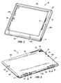
- Figs. 2 and 3 illustrate the case 28 in more detail.
- the case 28 includes a body 30 configured to receive the portable electronic device 24 ( Fig. 1 ).
- the body 30 has a front portion 40 and a back portion 44.
- the illustrated front and back portions 40, 44 connect together in a clamshell-type manner to at least partially enclose the portable electronic device 24. When connected together, the front and back portions 40, 44 form four sidewalls 48A-D extending around a perimeter of the portable electronic device.
- the front portion 40 defines an opening 52 through which a screen 56 ( Figs. 4 and 8 ) of the portable electronic device 24 is visible and accessible.
- the back portion 44 extends across and covers a backside of the portable electronic device 24. In the illustrated embodiment, the back portion 44 defines an aperture 60 through which a camera 64 of the device 24 is accessible.
- the back portion 44 may define additional apertures, openings, or slots to access other components of the device 24.
- the sidewalls 48A-D define slots or openings to access various components of the device 24.
- the illustrated sidewalls 48A-D define a port 68 (e.g., a charging port) that connects to the device 24.
- the charging port 68 is coupled to a pass-through connector 70.
- the pass-through connector 70 is housed between the front and back portions 40, 44 of the case 28 and connects to a charging port of the portable electronic device 24.
- the pass-through connector 70 provides access to the charging port of the portable electronic device 24 via the charging port 68 in the case 28 when the device 24 is positioned within the case 28.
- the illustrated sidewalls 48A-D also include a lock slot 72 that is configured to receive a locking head of a cable lock, such as a MicroSaver® lock sold by Kensington.
- the cable lock is operable to secure the case 28 to an immovable object, such as a desk, table, chair, wall, or the like.
- the port 68 and/or the lock slot 72 may be located elsewhere on the case 28.
- the case 28 also includes two attachment structures 76, 80 formed in the back portion 44.
- the first attachment structure 76 includes two keyhole-shaped apertures 84 formed adjacent opposing sidewalls 48B, 48D of the case 28.
- the apertures 84 are configured to receive projections extending from the folio 32 ( Figs. 4-7 ) to selectively attach the case 28 to the folio 32.
- the second attachment structure 80 includes two guide slots 88 and two rectangular apertures 92.
- the illustrated guide slots 88 are located adjacent the lower sidewall 48A of the case 28.
- the slots 88 are configured to receive guide rails 96 ( Figs. 11-12 ) extending from the dock 36 to help properly align the case 28 on the dock 36.
- each of the illustrated attachment structures 76, 80 includes two or more apertures, in other embodiments each attachment structure 76, 80 may include a single aperture or other suitable connecting feature.
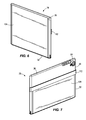
- Figs. 4-7 illustrate the case 28 attached to the folio 32.
- the folio 32 includes a front cover 104, a back cover 108, and an attachment member 112.
- the front cover 104 is attached to the back cover 108 at a hinge 116 so that the front cover 104 can move (e.g., pivot) relative to the back cover 108.
- the attachment member 112 is coupled to an edge of the back cover 108 opposite the front cover 104.
- the attachment member 112 is configured to extend across the case 28 and engage the two keyhole-shaped apertures 84 ( Fig. 3 ) of the first attachment structure 76.
- the attachment member 112 and the apertures 84 allow the folio 32 to be selectively and releaseably attached to the case 28.
- the front and back covers 104, 108 may be composed of a relatively soft and flexible material, such as fabric, and the attachment member 112 may be composed of a relatively rigid material, such as hard plastic.
- the covers 104, 108 and the attachment member 112 may be formed of other suitable materials.
- the front and back covers 104, 108 may be folded to form a triangular stand.
- the folio 32 can support the case 28, and thereby the portable electronic device 24, at multiple viewing angles.
- the lower sidewall 48A of the case 28 engages an inner surface 120 of the front cover 104 to support the case 28 and the portable electronic device 24 at the different viewing angles.
- the front and back covers 104, 108 may also be folded to a closed position to surround the case 28.
- the front cover 104 When in the closed position, the front cover 104 extends across the opening 52 in the case 28 to cover and protect the screen 56 of the portable electronic device 24.
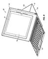
- the folio 32 may also include a keyboard 124.
- the illustrated keyboard 124 is a wireless keyboard that communicates with the portable electronic device 24 in the case 28 via a short-range network (e.g., via Bluetooth).
- the keyboard 124 magnetically couples to the inner surface 120 of the front cover 104 and is adjustable (i.e., movable along the inner surface 120) relative to the front cover 104.
- the keyboard 124 also engages the lower sidewall 48A of the case 28 to inhibit the case 28 from sliding along the front cover 120.
- the lower sidewall 48A of the case 28 may rest directly on top of the keyboard 124 to achieve a desired viewing angle of the portable electronic device 24.
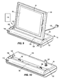
- Fig. 9 illustrates the portable electronic device 24 attached to the dock 36.
- the dock 36 or stand, includes a housing 128.
- the housing 128 is configured to couple to the portable electronic device 24. When coupled together, the illustrated housing 128 also supports the device 24.
- the housing 128 defines a slot 132 ( Fig. 10 ).
- the slot 132 receives a lower portion of the case 28 to connect the case 28 to the dock 36.
- the dock 36 is operable to secure the case 28, and thereby the portable electronic device 24, to the housing 128 using the lock mechanism 100 ( Fig. 13 ).
- the dock 36 may directly engage the portable electronic device 24.
- the case 28 may be omitted, and lock mechanism 100 ( Fig. 13 ) of the dock 36 may be configured to directly engage surfaces of or apertures formed in the portable electronic device 24 to secure the device 24 to the housing 128.
- "portable electronic device” can refer to the device 24 by itself or to the device 24 and the case 28 together.
- direct engagement of the lock mechanism 100 with the case 28 can also be considered engagement of the lock mechanism 100 with the device 24.
- a cord 133 extends from the housing 128.
- the illustrated cord 133 is a power cord that supplies power to the dock 36 and the portable electronic device 24 through the dock 36.
- the cord 133 may also or alternatively be a data cable (e.g., a USB cable, an HDMI cable, a network cable, or the like) to provide a data connection to the dock 36 and the portable electronic device 24 through the dock 36.
- the data cable may input/output audio and/or video from the portable electronic device 24, or the data cable may provide a network connection for the dock 26 and the portable electronic device 24.
- two ports 134A, 134B are formed in a rear surface of the housing 128.
- the first port 134A provides a power connection to the dock 36.
- the second port 134B provides a data connection to the dock 36.
- the power and data connections may be integrated into a single port and cord.
- the illustrated dock 36 also includes a lock slot 135 formed in the rear surface of the housing 128. Similar to the lock slot 72 ( Figs. 2 and 3 ) formed in the case 28, the lock slot 135 is configured to receive a locking head of a cable lock, such as a MicroSaver® lock sold by Kensington.
- the cable lock is configured to secure the dock 26 to an immovable object, such as a desk, table, chair, wall, or the like.
- the power cord and the cable lock may be combined into a single element that both provides power to the dock 36 and secures the dock 36 in place.
- the dock 36 may be secured to an immovable object with fasteners.
- the dock 36 may be screwed, bolted, and/or glued to a desk or table.
- the dock 36 may be mounted to other structures, such as an articulable stand or arm on a desk.
- the illustrated dock 36 includes an elastomeric member 136 and the two guide rails 96 positioned within the slot 132.
- the elastomeric member 136 is a rubber bar that extends across the slot 132 to engage the case 28.
- the elastomeric member 136 helps stabilize the case 28 within the slot 132 via a frictional engagement.
- the guide rails 96 extend into the slot 132 opposite from the elastomeric member 136.
- the guide rails 96 are spaced apart and are configured to fit within the guide slots 88 ( Fig. 3 ) in the case 28.
- the guide rails 96 are generally T-shaped or dovetail-shaped to inhibit the case 28 from shifting side-to-side and front-to-back within the slot 132.
- the guide rails 96 and the guide slots 88 may have other suitable shapes or configurations.
- the dock 36 also includes a connector 140 extending from a bottom surface of the slot 132.
- the connector 140 is configured to extend into the port 68 ( Fig. 3 ) formed in the case 28 to provide power from the dock 36 to the portable electronic device 24 within the case 28.
- the connector 140 may be a standard USB connector, a micro USB connector, an HDMI connector, a pogo pin connector, a proprietary connector, or the like.
- An indicator light 144 (e.g., an LED) is located on the housing 128 to provide a visual indication to a user when the case 28 is properly connected to the dock 36 and the portable electronic device 24 is charging.
- the illustrated connector 140 is also a data connector. As such, the connector 140 may be used for data synching, audio input and output, video input and output, or the like.
- the dock 36 may include a short-range wireless connector (e.g., a Bluetooth connector) to provide these additional functions.
- the dock 36 includes an actuator 142 supported by the housing 128 and electrically coupled to the connector 140.
- the illustrated actuator 142 is a charge and sync button that selectively establishes the power and data connection between the portable electronic device 24 and the dock 36. For example, actuating (e.g., depressing) the actuator 142 will initiate charging and/or data syncing of the portable electronic device 24 while the device 24 is connected to the dock 36; and actuating the actuator 142 again will stop charging and/or data synching the portable electronic device 24.
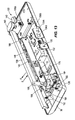
- the illustrated dock 36 further includes the lock mechanism 100.
- the lock mechanism 100 is operable to secure the case 28 within the slot 132 so that the case 28, and thereby the portable electronic device 24, cannot be removed (e.g., pulled out of) the slot 132.
- the lock mechanism 100 includes a hinge plate 148, a solenoid 152, a circuit board 156A-B, and an actuator 160.
- the hinge plate 148 is pivotally coupled within the housing 128 by a pin 164 and includes two projections 168.
- the projections 168 selectively extend into the slot 132 and engage the apertures 92 ( Fig. 3 ) on the case 28 to secure the case 28 in place.
- a biasing member 172 biases the hinge plate 148 toward the slot 132 (i.e., in the direction of arrow A) so that the projections 108 move toward an engaged position with the case 28.
- the biasing member 172 is a coil spring positioned between the hinge plate 148 and a bracket 176.
- other suitable biasing members such as torsion springs positioned around the pin 164, may also or alternatively be employed.
- the lock mechanism 100 may include multiple biasing members to bias the hinge plate 148 toward the engaged position.
- the projections 168 may likewise engage corresponding apertures in the device 24.
- the projections 168 may be replaced with one or more high-friction pads that engage one or more surfaces of the device 24.
- the pads may grip or press on the device 24 to clamp the device 24 within the slot 132 (e.g., between the pads and the elastomeric member 136).
- other suitable lock mechanisms 100 that are configured to engage the case 28 and/or the device 24 may also or alternatively be employed.
- the solenoid 152 is coupled to the hinge plate 148 and controlled by the circuit board 156A-B. When energized, the solenoid 152 pulls the hinge plate 148 away from the slot 132 against the bias of the biasing member 172 (i.e., in the direction of arrow B) so that the projections 168 move away from and disengage the case 28. As further discussed below, the solenoid 152 is energized when a wireless key 178 ( Fig. 9 ) is within a suitable range of the dock 36 (e.g., within about five feet) and the actuator 160 is actuated. When the solenoid 152 is not actuated, the hinge plate 148 is returned to the engaged position by the biasing member 172 to secure the case 28 in the slot 132. The projections 168 are shaped so that the case 28 can be inserted into the slot 132 without energizing the solenoid 152, but are only moved out of the slot 132 by energizing the solenoid 152.
- the circuit board 156A-B is positioned within the housing 128 and electrically coupled between the solenoid 152 and the actuator 160.
- the circuit board 156A-B includes a processor and a transceiver. In the illustrated embodiment, the circuit board 156A-B is split into two separate boards that communicate with each other. In other embodiments, the circuit board 156A-B may be single board.
- the circuit board 156A-B receives wireless signals from the wireless key 178 ( Fig. 9 ) via the transceiver to allow operation of the lock mechanism 100.
- the processor of the circuit board 156A-B receives the wireless signals from the wireless key 178 when the key 178 is within a suitable range of the dock 36.
- the processor of the circuit board 156A-B also receives a signal when the actuator 160 is actuated. When the processor receives both types of signals, the processor outputs a signal to energize the solenoid 152, thereby moving the lock mechanism 100 to the disengaged position.
- the circuit board 156A-B is also electrically coupled between the connector 140 and the actuator 142 to control power and data synching between the dock 38 and the portable electronic device 24.
- the actuator 160 is a button supported by the housing 128. As noted above, the actuator 160 is actuatable by a user to selectively energize the solenoid 152 and move the hinge plate 148 out of engagement with the case 28. After the actuator 160 is actuated (and if the wireless key 178 is within range of the dock 36), the solenoid 152 remains energized for a predetermined period of time (e.g., about five seconds) so that a user can remove the case 28 from the dock 36. In other embodiments, the actuator 160 may be located elsewhere. For example, the actuator 160 may be part of the wireless key 178 ( Fig. 9 ) or part of the portable electronic device 24.
- the actuator 160 may be a mechanical button or switch supported by the key 178, the device 24, or the case 28.
- the actuator 160 may be part of a software program (e.g., a button displayed on the screen 56 of the device 24 or on a screen of the key 178) that is selectively actuated by a user.
- the illustrated lock mechanism 100 also includes a mechanical latch release 180.
- the mechanical latch release 180 is physically coupled to the lock mechanism 100.
- the mechanical latch release 180 is usable if, for example, the dock 36 is not connected to a power source to properly power the solenoid 152 and the circuit board 156A-B, or if the wireless key 178 is not available.
- the mechanical latch release 180 includes a lock cylinder 184.
- the lock cylinder 184 is configured to receive a key 188 that is inserted by a user. The user can then rotate the key 188 to actuate the lock cylinder 184 and pivot the hinge plate 148 against the bias of the biasing members 172 so that the projections 168 disengage the case 28.
- a link 192 extends between the lock cylinder 184 and the hinge plate 148 to pull the hinge plate 148 as the lock cylinder 184 rotates.
- other suitable mechanical latch releases 180 may alternatively be employed.
- Figs. 14 and 15 illustrate the case 28 being inserted into the slot 132 in the dock 36.
- the case 28 is insertable in a generally downward motion so that the guide slots 88 on the case 28 slide into the guide rails 96 on the dock 36, and so that the projections 168 of the hinge plate 148 extend into the apertures 92 in the case 28.
- the rails 96 help properly position the case 28 within the slot 132 so that the apertures 92 are properly aligned with the projections 168.
- the case 28 is captured between the elastomeric member 136 and the lock mechanism 100 to secure the case 28, and thereby the portable electronic device 24, to the dock 36.
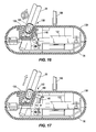
- Figs. 16 and 17 illustrate the lock mechanism 100 moving between the engaged position ( Fig. 16 ) and the disengaged position ( Fig. 17 ).
- some of the internal components of the dock 36 are removed to facilitate illustrating the hinge plate 148 and the solenoid 152.
- the solenoid 152 When in the engaged position, the solenoid 152 is not energized. In this position, the biasing member 172 biases the projections 168 on the hinge plate 148 into engagement with the case 28. The case 28 and the device 24 are, therefore, secured within the slot 132 of the dock 36.
- the solenoid 152 is energized.
- the solenoid 152 pulls the hinge plate 148 against the bias of the biasing member 172 to pivot the projections 168 away from the case 28 against the bias of the biasing member 172.
- the case 28 and the device 24 are, therefore, removable from the slot 132 of the dock 36.
- Fig. 18 is a flowchart depicting operation of the logic controlling the lock mechanism 100 in the dock 36.
- the logic is performed by the printed circuit board 156A-B coupled to the solenoid 152. More particularly, the logic is performed by the processor of the printed circuit board 156A-B.
- the circuit board 156A-B receives signals from the wireless key 178 ( Fig. 9 ).
- the wireless key 178 used to "unlock" the lock mechanism 100 may be a fob, a smartphone, or other apparatus that is capable of transmitting a wireless signal and is carried by a user.
- the lock mechanism 100 is initially in the engaged or locked position to inhibit the case 28 from being removed from the dock 36.
- the circuit board 156A-B checks whether the actuator 160 has been actuated by a user. If so, the circuit board 156A-B begins searching for the wireless key 178 at steps 208 and 212. The circuit board 156A-B pairs with the wireless key 178 at 212 to verify that the key 178 is authorized to interact with the dock 36.
- the solenoid 152 is energized to move the lock mechanism 100 to the disengaged or unlocked position (step 220) so that the case 28 can be removed from the dock 36.
- the lock mechanism 100 remains in the unlocked position for, for example, about five seconds before returning to the locked position. If the wireless key 178 is not within range, the solenoid 152 is not energized so that the lock mechanism 100 remains in the locked position (step 224).
- the circuit board 156A-B may periodically check whether the wireless key 178 is within range, regardless of whether the actuator 160 has been actuated. In such embodiments, actuating the actuator 160 (while the wireless key 178 is in range) will energize the solenoid 152 to move the lock mechanism 100 to the unlocked position without requiring the circuit board 156A-B to recheck if the key 178 is in range.
- Fig. 19 is a flowchart depicting operation of the logic controlling the wireless key 178 that communicates with the dock 36.
- the wireless key 178 periodically scans or searches for the dock 36. If the dock 36 is found, the wireless key 178 establishes a connection (i.e., pairs) with the dock 36 at step 304. Then, the wireless key 178 periodically checks at step 308 if the dock 36 has become disconnected from (e.g., moved out of range of) the wireless key 178. In some embodiments, the dock 36 and/or the wireless key 178 may be programmed to have a range between about five feet and about fifty feet. If the wireless key 178 and the dock 36 become disconnected (i.e., unpaired), the wireless key 178 goes back to step 300 to periodically scan for the dock 36.
Landscapes
- Engineering & Computer Science (AREA)
- Theoretical Computer Science (AREA)
- Computer Hardware Design (AREA)
- Human Computer Interaction (AREA)
- Physics & Mathematics (AREA)
- General Engineering & Computer Science (AREA)
- General Physics & Mathematics (AREA)
- Microelectronics & Electronic Packaging (AREA)
- Computer Security & Cryptography (AREA)
- Casings For Electric Apparatus (AREA)
Applications Claiming Priority (2)
| Application Number | Priority Date | Filing Date | Title |
|---|---|---|---|
| US201361896303P | 2013-10-28 | 2013-10-28 | |
| US201461924284P | 2014-01-07 | 2014-01-07 |
Publications (1)
| Publication Number | Publication Date |
|---|---|
| EP2866121A1 true EP2866121A1 (fr) | 2015-04-29 |
Family
ID=51870832
Family Applications (2)
| Application Number | Title | Priority Date | Filing Date |
|---|---|---|---|
| EP20140190646 Withdrawn EP2866121A1 (fr) | 2013-10-28 | 2014-10-28 | Étui de dispositif électronique portable, agenda et socle |
| EP20140190645 Withdrawn EP2866120A1 (fr) | 2013-10-28 | 2014-10-28 | Étui de dispositif électronique portable, agenda et socle |
Family Applications After (1)
| Application Number | Title | Priority Date | Filing Date |
|---|---|---|---|
| EP20140190645 Withdrawn EP2866120A1 (fr) | 2013-10-28 | 2014-10-28 | Étui de dispositif électronique portable, agenda et socle |
Country Status (2)
| Country | Link |
|---|---|
| US (2) | US20150116926A1 (fr) |
| EP (2) | EP2866121A1 (fr) |
Families Citing this family (25)
| Publication number | Priority date | Publication date | Assignee | Title |
|---|---|---|---|---|
| US9875607B2 (en) * | 2011-07-13 | 2018-01-23 | Igt | Methods and apparatus for providing secure logon to a gaming machine using a mobile device |
| US9017092B1 (en) | 2014-05-07 | 2015-04-28 | Microsoft Technology Licensing, Llc | Electronic connector |
| JP2016051928A (ja) * | 2014-08-28 | 2016-04-11 | 株式会社東芝 | アタッチメント装置、カバー装置およびアタッチメントシステム |
| US9728915B2 (en) | 2015-05-19 | 2017-08-08 | Microsoft Technology Licensing, Llc | Tapered-fang electronic connector |
| US9557778B2 (en) | 2015-06-27 | 2017-01-31 | Intel Corporation | Hinge for a device |
| KR102393165B1 (ko) * | 2015-07-31 | 2022-05-02 | 엘지전자 주식회사 | 디스플레이 장치 |
| US10277275B2 (en) | 2015-09-08 | 2019-04-30 | Google Llc | Audio media streaming device |
| US9736531B2 (en) | 2015-09-08 | 2017-08-15 | Google Inc. | Video media streaming device |
| US9740245B2 (en) * | 2015-10-05 | 2017-08-22 | Microsoft Technology Licensing, Llc | Locking mechanism |
| US9660380B1 (en) | 2016-01-22 | 2017-05-23 | Microsoft Technology Licensing, Llc | Alignment tolerant electronic connector |
| US9880586B2 (en) * | 2016-02-09 | 2018-01-30 | Lenovo (Singapore) Pte. Ltd. | Modular display system interface |
| EP3433681B1 (fr) * | 2016-03-24 | 2025-03-12 | Razer (Asia-Pacific) Pte. Ltd. | Stations d'accueil, dispositifs informatiques, procédés de commande d'une station d'accueil et procédés de commande d'un dispositif informatique |
| US11054862B2 (en) * | 2016-04-26 | 2021-07-06 | Microsoft Technology Licensing, Llc | Undocking assist mechanisms and methods of use |
| US9785196B1 (en) * | 2016-08-18 | 2017-10-10 | Microsoft Technology Licensing, Llc | Capture connector for actuated locking devices |
| CN106790834B (zh) * | 2017-02-27 | 2019-04-19 | 深圳罗马仕科技有限公司 | 移动终端保护组件及其保护框和背夹电池 |
| US10511599B2 (en) | 2017-03-13 | 2019-12-17 | Microsoft Technology Licensing, Llc | System to filter impossible user travel indicators |
| US10794093B2 (en) | 2017-05-19 | 2020-10-06 | Microsoft Technology Licensing, Llc | Method of optimizing memory wire actuator energy output |
| US10445533B2 (en) | 2017-06-30 | 2019-10-15 | Microsoft Technology Licensing, Llc | Method of optimizing memory wire actuator energy output |
| US10768676B2 (en) * | 2017-09-07 | 2020-09-08 | Intel Corporation | Docking systems and methods for electronic devices |
| US10303214B2 (en) | 2017-10-17 | 2019-05-28 | Microsoft Technology Licensing, Llc | Docking mechanisms and methods of restraining two portions of a computing device |
| US10511127B2 (en) | 2018-03-20 | 2019-12-17 | Microsoft Technology Licensing, Llc | High-speed electronic connector |
| CN110611219B (zh) * | 2018-06-15 | 2021-02-12 | 神讯电脑(昆山)有限公司 | 连动机构模块及扩充座 |
| US10788857B2 (en) * | 2018-09-05 | 2020-09-29 | ACCO Brands Corporation | Dock for a portable electronic device |
| USD901507S1 (en) | 2018-09-05 | 2020-11-10 | ACCO Brands Corporation | Electronic dock |
| US10903612B1 (en) * | 2019-06-26 | 2021-01-26 | Amazon Technologies, Inc. | Dock device with integrated clamp |
Citations (4)
| Publication number | Priority date | Publication date | Assignee | Title |
|---|---|---|---|---|
| EP2182608A2 (fr) * | 2008-10-29 | 2010-05-05 | SA Shuang | Chargeur d'accueil pour charger un dispositif électronique portatif avec ou sans couvercle de boîte protecteur assemblé sur celui-ci |
| US20130021164A1 (en) * | 2011-07-21 | 2013-01-24 | Datamax-O'neil Corporation | Docking cradle including a releasable latching mechanism for engaging a handheld device therein |
| WO2013103082A1 (fr) * | 2012-01-06 | 2013-07-11 | ソニー株式会社 | Structure externe et appareil électronique |
| US20140073262A1 (en) | 2012-09-12 | 2014-03-13 | ACCO Brands Corporation | Proximity tag for object tracking |
Family Cites Families (65)
| Publication number | Priority date | Publication date | Assignee | Title |
|---|---|---|---|---|
| US5144290A (en) * | 1988-10-31 | 1992-09-01 | Kabushiki Kaisha Toshiba | Display unit attachment device |
| JPH04233797A (ja) * | 1990-12-28 | 1992-08-21 | Sony Corp | 電子機器保持装置 |
| US5417319A (en) * | 1994-03-22 | 1995-05-23 | Hydrabaths, Inc. | Security container for display of audio and video media |
| US5552957A (en) * | 1994-09-09 | 1996-09-03 | International Business Machines Corporation | Portable computer field kit |
| JPH10198459A (ja) * | 1996-12-24 | 1998-07-31 | Internatl Business Mach Corp <Ibm> | 携帯型コンピュータ用ドッキング装置 |
| US5995366A (en) * | 1998-01-16 | 1999-11-30 | Dell U.S.A., L.P. | Computer anti-theft system and method |
| US7612999B2 (en) * | 1998-09-18 | 2009-11-03 | Flo Healthcare Solutions, Llc | Mobile clinical workstation |
| US6108200A (en) * | 1998-10-13 | 2000-08-22 | Fullerton; Robert L. | Handheld computer keyboard system |
| US6532152B1 (en) * | 1998-11-16 | 2003-03-11 | Intermec Ip Corp. | Ruggedized hand held computer |
| US6388877B1 (en) * | 1999-02-04 | 2002-05-14 | Palm, Inc. | Handheld computer with open accessory slot |
| US6626362B1 (en) * | 1999-02-16 | 2003-09-30 | Mark Steiner | Protective cover for a hand held device |
| US6317313B1 (en) * | 1999-11-09 | 2001-11-13 | Interlogix, Inc. | Case and cover for an electronic device |
| WO2001079975A2 (fr) * | 2000-04-19 | 2001-10-25 | Enfora, Inc. | Systeme et dispositif de portefeuille sans fil |
| DE10202061A1 (de) * | 2001-01-18 | 2002-09-19 | Andreas Peiker | Anordnung mit Mobiltelefon |
| US6829140B2 (en) * | 2001-12-17 | 2004-12-07 | Toshiba America Information Services, Inc. | Portable computer usable in laptop and tablet configurations |
| US20110289123A1 (en) * | 2001-12-27 | 2011-11-24 | Denison William D | Method for Controlling and Recording the Security of an Enclosure |
| GB2386346B (en) * | 2002-03-12 | 2005-06-15 | Eleksen Ltd | Flexible foldable keyboard |
| US7542052B2 (en) * | 2002-05-31 | 2009-06-02 | Hewlett-Packard Development Company, L.P. | System and method of switching viewing orientations of a display |
| US6952343B2 (en) * | 2002-06-11 | 2005-10-04 | Fujitsu Limited | Functional expansion apparatus and method for attaching electronic apparatus to the functional expansion apparatus |
| US6772879B1 (en) * | 2002-06-25 | 2004-08-10 | The Gem Group, Inc. | Standing case for personal digital assistant |
| TWM245484U (en) * | 2003-11-10 | 2004-10-01 | Tatung Co | Structure for locking a portable computer to its docket |
| JP4411151B2 (ja) * | 2004-06-30 | 2010-02-10 | ソニー・エリクソン・モバイルコミュニケーションズ株式会社 | 通信端末装置及び通信システム |
| TWM259501U (en) * | 2004-07-09 | 2005-03-21 | Tatung Co | Foldable computer cover |
| US7239505B2 (en) * | 2004-10-08 | 2007-07-03 | Microsoft Corporation | Direct hinge for optimizing conversion |
| US7345871B2 (en) * | 2005-02-01 | 2008-03-18 | Hewlett-Packard Development Company, L.P. | System and method for locking a tablet computer display |
| US20120011367A1 (en) * | 2005-04-21 | 2012-01-12 | Denison William D | Method for Controlling and Recording the Security of an Enclosure |
| US7480138B2 (en) * | 2005-06-30 | 2009-01-20 | Symbol Technologies, Inc. | Reconfigurable mobile device docking cradle |
| US20070049071A1 (en) * | 2005-07-05 | 2007-03-01 | Jackson W S | Recharging apparatus for portable electronic devices |
| EP1793351B1 (fr) * | 2005-11-29 | 2015-07-15 | Kabushiki Kaisha Tokai-Rika-Denki-Seisakusho | Dispositif portable avec clé mécanique |
| US20070195490A1 (en) * | 2006-02-13 | 2007-08-23 | Howell Sean V | Apparatus And Method For Attaching An Electronic Module To A Lock Assembly |
| JP4192954B2 (ja) * | 2006-02-16 | 2008-12-10 | トヨタ自動車株式会社 | 受信回路 |
| US8487738B2 (en) * | 2006-03-20 | 2013-07-16 | Medical Solutions, Inc. | Method and apparatus for securely storing medical items within a thermal treatment system |
| US8179672B2 (en) * | 2006-06-30 | 2012-05-15 | National Products, Inc. | Portable device docking station |
| CN101641657B (zh) * | 2007-03-16 | 2012-06-06 | 富士通株式会社 | 支架和电子设备系统 |
| JP2009151708A (ja) * | 2007-12-21 | 2009-07-09 | Toshiba Corp | 電子機器のドッキングステーション |
| US7978466B2 (en) * | 2008-02-27 | 2011-07-12 | L&P Property Management Company | Computer docking station for a vehicle |
| CN101569537B (zh) * | 2008-04-29 | 2014-07-09 | Ge医疗系统环球技术有限公司 | 扩展坞与超声波诊断系统 |
| US8511633B2 (en) * | 2009-01-16 | 2013-08-20 | Amazon Technologies, Inc. | Accessory attachment mechanism |
| AU2010253755B2 (en) * | 2009-05-29 | 2015-08-27 | Acco Brands Usa Llc | Security apparatus including attachment device |
| US7911779B1 (en) * | 2009-09-30 | 2011-03-22 | L&P Property Management Company | Computer docking station |
| US8334765B2 (en) * | 2010-05-24 | 2012-12-18 | Keylockit Ltd. | Wireless network apparatus and method for lock indication |
| TWI439215B (zh) * | 2010-05-28 | 2014-05-21 | Asustek Comp Inc | 擴充基座及使用其之電子裝置 |
| US20120111881A1 (en) * | 2010-06-07 | 2012-05-10 | 360 Mobility Solutions, Llc | Protective cases for electronic devices |
| US20120153116A1 (en) * | 2010-06-25 | 2012-06-21 | Doug Harrison | Convertible Case for a Tablet Computer |
| US8328008B2 (en) * | 2010-08-10 | 2012-12-11 | Incase Designs Corp. | Case for electronic tablet |
| US8816816B2 (en) * | 2010-11-17 | 2014-08-26 | Symbol Technologies, Inc. | Methods and apparatus for securing a portable device |
| WO2012094526A1 (fr) * | 2011-01-05 | 2012-07-12 | Mophie, Inc. | Support de tablette électronique |
| US9335793B2 (en) * | 2011-01-31 | 2016-05-10 | Apple Inc. | Cover attachment with flexible display |
| US20120224316A1 (en) * | 2011-03-03 | 2012-09-06 | Shulenberger Arthur M | Foldable carrying case for a tablet computer |
| JP5538460B2 (ja) * | 2011-04-06 | 2014-07-02 | パナソニック株式会社 | 拡張機器、およびそれを備えた情報処理システム |
| TWI420775B (zh) * | 2011-05-26 | 2013-12-21 | 鴻海精密工業股份有限公司 | 具有安全功能的充電座 |
| US8869573B2 (en) * | 2011-06-14 | 2014-10-28 | ACCO Brands Corporation | Protective case for physically securing a portable electronic device |
| WO2012178168A2 (fr) * | 2011-06-23 | 2012-12-27 | Zagg Intellectual Property Holding Co., Inc. | Accessoire et support pour dispositifs électroniques, systèmes les intégrant et procédés associés |
| US20120327580A1 (en) * | 2011-06-23 | 2012-12-27 | Zagg Intellectual Property Holding Co., Inc. | Protective devices and systems for portable electronic devices and associated methods |
| US20130016467A1 (en) * | 2011-07-11 | 2013-01-17 | Allen Ku | Leather case with keyboard |
| TWI494741B (zh) * | 2011-08-16 | 2015-08-01 | Asustek Comp Inc | 接合組件及電子系統 |
| US8867202B2 (en) * | 2011-08-23 | 2014-10-21 | L&P Property Management Company | Docking station |
| US20130057199A1 (en) * | 2011-09-07 | 2013-03-07 | Albert G. Langella | Electrical junction box mounted electronic device charging station |
| US9182793B2 (en) * | 2011-10-14 | 2015-11-10 | Ergotron, Inc. | Tablet storage and transportation device |
| US8556327B1 (en) * | 2012-03-23 | 2013-10-15 | Toyota Motor Engineering & Manufacturing North America, Inc. | Fuel housing assemblies with integrated sealing retainer assemblies |
| US9327593B2 (en) * | 2012-03-29 | 2016-05-03 | Toyota Motor Engineering & Manufacturing North America, Inc. | Fuel housing assemblies with primary and secondary fuel door lock systems |
| KR101169059B1 (ko) * | 2012-03-30 | 2012-07-31 | 주식회사 빅솔론 | 휴대용 단말기를 이용한 포스 단말기 및 그 시스템 |
| US8844817B2 (en) * | 2013-01-05 | 2014-09-30 | Otter Products, Llc | Electronic device case for mobile point of sale |
| DE112013006354T5 (de) * | 2013-01-31 | 2015-10-08 | Hewlett-Packard Development Company, L.P. | Anzeigenbefestigungssystem |
| US9596914B2 (en) * | 2013-04-19 | 2017-03-21 | Joseph A. Zaloom | Tablet transformer |
-
2014
- 2014-10-28 EP EP20140190646 patent/EP2866121A1/fr not_active Withdrawn
- 2014-10-28 EP EP20140190645 patent/EP2866120A1/fr not_active Withdrawn
- 2014-10-28 US US14/525,751 patent/US20150116926A1/en not_active Abandoned
- 2014-10-28 US US14/525,765 patent/US20150116927A1/en not_active Abandoned
Patent Citations (5)
| Publication number | Priority date | Publication date | Assignee | Title |
|---|---|---|---|---|
| EP2182608A2 (fr) * | 2008-10-29 | 2010-05-05 | SA Shuang | Chargeur d'accueil pour charger un dispositif électronique portatif avec ou sans couvercle de boîte protecteur assemblé sur celui-ci |
| US20130021164A1 (en) * | 2011-07-21 | 2013-01-24 | Datamax-O'neil Corporation | Docking cradle including a releasable latching mechanism for engaging a handheld device therein |
| WO2013103082A1 (fr) * | 2012-01-06 | 2013-07-11 | ソニー株式会社 | Structure externe et appareil électronique |
| US20140376182A1 (en) * | 2012-01-06 | 2014-12-25 | Sony Corporation | External structure and electronic apparatus |
| US20140073262A1 (en) | 2012-09-12 | 2014-03-13 | ACCO Brands Corporation | Proximity tag for object tracking |
Also Published As
| Publication number | Publication date |
|---|---|
| US20150116926A1 (en) | 2015-04-30 |
| EP2866120A1 (fr) | 2015-04-29 |
| US20150116927A1 (en) | 2015-04-30 |
Similar Documents
| Publication | Publication Date | Title |
|---|---|---|
| EP2866121A1 (fr) | Étui de dispositif électronique portable, agenda et socle | |
| US10544895B2 (en) | Equipment mounting system | |
| US9141136B2 (en) | Tablet computer carrying case with retractable latch | |
| US11066004B2 (en) | Equipment mounting system | |
| US8649169B2 (en) | Systems and methods for securing mobile computing devices | |
| US8867202B2 (en) | Docking station | |
| US10307313B2 (en) | Equipment mounting system | |
| US5546334A (en) | Notebook computer system with a separable trackball | |
| CN101959379B (zh) | 电子设备及其卡止装置 | |
| US8074951B2 (en) | Quick release electronics platform | |
| US8724312B2 (en) | Mobile computer stand with integrated keyboard | |
| DK3169296T3 (en) | EQUIPMENT MOUNTING SYSTEM | |
| US20090278495A1 (en) | Charging and security station for multiple wireless tablets | |
| US20080151489A1 (en) | Electronic device quick connect system | |
| US20100053857A1 (en) | Latching device and electronic device using the same | |
| US20130148289A1 (en) | Systems and Methods for Securing Mobile Computing Devices | |
| EP1650382A3 (fr) | Dispositif antivol pour la fixation d'équipement informatique | |
| CN101664337B (zh) | 台车 | |
| US6189349B1 (en) | Single retracting security hook of desktop port replicator providing security for dissimilar multiple portable computers | |
| CN107076187A (zh) | 连结件 | |
| GB2461237A (en) | Electronic device restraint mechanism | |
| CN103935296B (zh) | 用于车辆顶部控制台的具有磁辅装置的滑动会话镜总成 | |
| TWM503731U (zh) | 具有轉動鎖固機構之固定裝置 | |
| EP1464244A1 (fr) | Dispositif de fermeture pour la connection ouvrable de plus qu'un languette en des directions différentes | |
| CN117759815A (zh) | 用于可穿戴装置的人机工程学闭锁和释放的方法、系统和设备 |
Legal Events
| Date | Code | Title | Description |
|---|---|---|---|
| PUAI | Public reference made under article 153(3) epc to a published international application that has entered the european phase |
Free format text: ORIGINAL CODE: 0009012 |
|
| 17P | Request for examination filed |
Effective date: 20141028 |
|
| AK | Designated contracting states |
Kind code of ref document: A1 Designated state(s): AL AT BE BG CH CY CZ DE DK EE ES FI FR GB GR HR HU IE IS IT LI LT LU LV MC MK MT NL NO PL PT RO RS SE SI SK SM TR |
|
| AX | Request for extension of the european patent |
Extension state: BA ME |
|
| RBV | Designated contracting states (corrected) |
Designated state(s): AL AT BE BG CH CY CZ DE DK EE ES FI FR GB GR HR HU IE IS IT LI LT LU LV MC MK MT NL NO PL PT RO RS SE SI SK SM TR |
|
| 17Q | First examination report despatched |
Effective date: 20171002 |
|
| STAA | Information on the status of an ep patent application or granted ep patent |
Free format text: STATUS: THE APPLICATION IS DEEMED TO BE WITHDRAWN |
|
| 18D | Application deemed to be withdrawn |
Effective date: 20180213 |