EP2866123A2 - Appareil de fonctionnement d'écran et procédé de fonctionnement de l'écran - Google Patents
Appareil de fonctionnement d'écran et procédé de fonctionnement de l'écran Download PDFInfo
- Publication number
- EP2866123A2 EP2866123A2 EP20140185303 EP14185303A EP2866123A2 EP 2866123 A2 EP2866123 A2 EP 2866123A2 EP 20140185303 EP20140185303 EP 20140185303 EP 14185303 A EP14185303 A EP 14185303A EP 2866123 A2 EP2866123 A2 EP 2866123A2
- Authority
- EP
- European Patent Office
- Prior art keywords
- screen
- operator
- face
- face direction
- predetermined
- Prior art date
- Legal status (The legal status is an assumption and is not a legal conclusion. Google has not performed a legal analysis and makes no representation as to the accuracy of the status listed.)
- Withdrawn
Links
Images




Classifications
-
- G—PHYSICS
- G06—COMPUTING OR CALCULATING; COUNTING
- G06F—ELECTRIC DIGITAL DATA PROCESSING
- G06F3/00—Input arrangements for transferring data to be processed into a form capable of being handled by the computer; Output arrangements for transferring data from processing unit to output unit, e.g. interface arrangements
- G06F3/01—Input arrangements or combined input and output arrangements for interaction between user and computer
- G06F3/011—Arrangements for interaction with the human body, e.g. for user immersion in virtual reality
-
- G—PHYSICS
- G06—COMPUTING OR CALCULATING; COUNTING
- G06F—ELECTRIC DIGITAL DATA PROCESSING
- G06F3/00—Input arrangements for transferring data to be processed into a form capable of being handled by the computer; Output arrangements for transferring data from processing unit to output unit, e.g. interface arrangements
- G06F3/01—Input arrangements or combined input and output arrangements for interaction between user and computer
- G06F3/011—Arrangements for interaction with the human body, e.g. for user immersion in virtual reality
- G06F3/012—Head tracking input arrangements
-
- G—PHYSICS
- G06—COMPUTING OR CALCULATING; COUNTING
- G06F—ELECTRIC DIGITAL DATA PROCESSING
- G06F3/00—Input arrangements for transferring data to be processed into a form capable of being handled by the computer; Output arrangements for transferring data from processing unit to output unit, e.g. interface arrangements
- G06F3/01—Input arrangements or combined input and output arrangements for interaction between user and computer
- G06F3/011—Arrangements for interaction with the human body, e.g. for user immersion in virtual reality
- G06F3/013—Eye tracking input arrangements
Definitions
- the present invention relates to a technique for enabling hands-free, non-contact operation of screen.
- Line-of-sight input There are known methods for using line of sight (referred to as “line-of-sight input") as a means for operating a device (e.g., see Non-Patent Documents 1 to 3).
- line-of-sight input Various applications for line-of-sight input are known, and for example, NTT DOCOMO, Inc. recently presented at CEATEC (Cutting-Edge IT & Electronics Comprehensive Exhibition) JAPAN 2012 a test model of an ibeam tablet terminal where pointer movement and screen scrolling that match the movement of a line of sight are possible.
- JP 2009-227246A discloses an example of using line of sight as a means for unlocking a lock for preventing erroneous operation of a car navigation apparatus.
- JP 2009-227246A is an example of background art.
- Non-Patent Document 1 Takehiko Ohno, Naoki Mukawa, Atsushi Yoshikawa, "An Eyeball Model Based Eye Tracking Method", Proceedings of the 8th Symposium on Sensing via Image Information, pp.
- Non-Patent Document 2 Yasuhiro Ono, Takahiro Okabe, Yoichi Sato, "Gaze Estimation from Low Resolution Images Insensitive to Segmentation Error” Proceedings of the Meeting on Image Recognition and Understanding (MIRU 2005), pp. 96-103, 2005 (Non-Patent Document 3) are also examples of background art.
- a screen operation apparatus for enabling operation of a screen by an operator, the screen operation apparatus comprising: a processor configured to operate as an image input unit configured to obtain images of a face of the operator at a predetermined time interval; a focus condition determination unit configured to, using the images obtained by the image input unit, determine whether or not the operator is focusing on the screen; a face direction condition determination unit configured to, using the images obtained by the image input unit, determine whether or not a face direction of the operator satisfies a predetermined condition; and a screen operation unit configured to execute a predetermined screen operation when the face direction condition determination unit determines that the face direction of the operator satisfies the predetermined condition and the focus condition determination unit determines that the operator is focusing on the screen.
- Embodiments of the present invention have been devised in view of the foregoing problems and it is an object thereof to provide a method by which hands-free, non-contact operation of a screen can be performed and there is less operational burden and operation is easier compared to conventional line-of-sight input.
- the first embodiment will describe an example in which a program for screen operation according to an aspect of the present invention is implemented in an electronic device (such as a smartphone), and screen operations, such as screen scrolling and page movement (page turning) in an application program (Web browser, e-mail software, document viewer, game, etc.) that operates on the electronic device, are performed using a combination of "line of sight" and "face direction".
- screen operations such as screen scrolling and page movement (page turning) in an application program (Web browser, e-mail software, document viewer, game, etc.) that operates on the electronic device, are performed using a combination of "line of sight" and "face direction”.
- FIGS. 1A to 1C a smartphone 1 and the face of an operator 2 operating the smartphone 1 are shown schematically from the side.
- FIG. 1A is an example of a correct screen operation.
- An example is shown in which the operator 2 focuses on the screen of the smartphone 1 and while maintaining that state, faces downward, and accordingly, the screen scrolls down.
- the association between the face direction and the screen operation is not limited to this and any other association may be used. According to this operation method, the operator 2 can easily instruct a desired screen operation without using his or her hands.
- FIG. 1B shows an action of returning the line of sight to the screen from a state in which the eyes have been taken away from the screen.
- FIG. 1C shows a situation in which the line of sight has been shifted to the floor from a state in which the operator 2 is focusing on the screen. In either case, it is the same as FIG. 1A in terms of the movement of the face direction.
- FIG. 2 is a diagram schematically showing a functional configuration of a screen operation apparatus according to the first embodiment.
- the screen operation apparatus 10 is for enabling operation of a screen of the smartphone 1 by the operator 2 and is implemented as an operation input interface of the smartphone 1.
- the screen operation apparatus 10 has an image input unit 11, a face direction estimation unit 12, a line-of-sight estimation unit 13, a focus condition determination unit 14, a face direction condition determination unit 15, a screen operation unit 16, and a record storage unit 17. These functions are realized by a program for screen operation stored in a memory (storage apparatus) of the smartphone 1 being executed by a processor.
- the record storage unit 17 is a storage region retained in a working memory. Note that all or a portion of these functional elements may be configured by a dedicated chip (ASIC, FPGA, or the like).
- the image input unit 11 is a function for obtaining images of the face of the operator 2 from a built-in camera of the smartphone 1.
- images are obtained at a predetermined time interval (e.g., a few to around a dozen frames in one second) by the image input unit 11.
- the face direction estimation unit 12 is a function of estimating the face direction of the operator 2 by analyzing the images obtained by the image input unit 11. Many algorithms for estimating the face direction from the images have been proposed (e.g., see Non-Patent Document 1), and any algorithm may be employed.
- the face direction estimation unit 12 of the present embodiment estimates the position and size of the face, the face direction, the positions of facial parts such as eyes, nose, and mouth, and the like using a model fitting method in which a 3D model configured by groups of feature points of facial parts is applied to a face portion in an image.
- the position in the depth direction (optical axis direction of camera) of the face can be estimated from the size of the face in the image, and the like.
- the face direction is obtained as an orientation vector of the 3D face model (3D vector).
- the 3D vector can be represented in any coordinate system, such as xyz, or roll-pitch-yaw, and in the present embodiment, a description is given using an xyz coordinate system.
- the line-of-sight estimation unit 13 is a function of estimating the direction of the line of sight of the operator 2 by analyzing the images obtained by the image input unit 11.
- Many algorithms for line-of-sight detection and line-of-sight estimation have been proposed (e.g., see Non-Patent Documents 1 to 3), and any algorithm may be employed.
- the result of the model fitting of the face direction estimation unit 12 is used to estimate the size and central position of the eyeballs based on the size of the face, the position of the eyes, and the like, and to detect the positions of the pupils based on the face image, and a vector connecting the center of the eyeball and the center of the pupil can be assumed to be the line-of-sight direction.
- the line-of-sight direction may be estimated by learning the features (relative positions, darkness and lightness, texture, etc. of whites and pupils of eyes) of images of eyes in various line-of-sight directions in advance and evaluating the degree of similarity between the features.
- the line-of-sight direction is also obtained as a 3D vector.
- a portion of the values of the 3D vectors of the line-of-sight directions may be made common with the values of the 3D vectors for the face directions (e.g., the coordinates of the start point are made common, etc.), and the 3D vectors of the line-of-sight direction may be represented using the relative values of the 3D vectors of the face direction (relative angles using the face direction 3D vector as a reference, etc.).
- the focus condition determination unit 14 is a function of determining whether or not the operator 2 is focusing on the screen of the smartphone 1.
- the face direction condition determination unit 15 is a function of determining whether or not the face direction of the operator 2 satisfies a predetermined condition.
- the screen operation unit 16 is a function of executing a corresponding screen operation based on the determination results of the focus condition determination unit 14 and the face direction condition determination unit 15.
- the record storage unit 17 is a storage region for temporarily storing information such as the face direction, line of sight, and the like for each image.
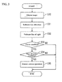
- FIG. 3 is a flowchart of main processing performed by the screen operation apparatus according to the first embodiment. This processing is repeatedly executed at a predetermined time interval while a screen that is to be the operation target is displayed on the smartphone 1 (for example, when a screen capable of scrolling and page movement is displayed). As described above, a few to around a dozen frames of images are processed per second in the present embodiment, and therefore the flow in FIG. 3 is executed at a few to around a dozen cycles per second.
- the image input unit 11 obtains one image from the camera (step S30).
- the image that is to be used may be a monochrome image or a color image.
- step S31 the face direction estimation unit 12 estimates the face direction from the image obtained in step S30.
- information regarding the 3D vector for the face direction, the size and position of the face, the positions of the facial parts, and the like can be obtained.
- the results of the face direction estimation are stored in the record storage unit 17.
- step S32 the line-of-sight estimation unit 13 estimates the line of sight using the image obtained in step S30. In the case of using the result of the face direction estimation, it is sufficient that the necessary information is loaded from the record storage unit 17. As a result of the line-of-sight estimation, information regarding the position of the eyes of the operator 2, 3D vectors for the line-of-sight direction, and the like are obtained. The result of the line-of-sight estimation is stored in the record storage unit 17.
- the focus condition determination unit 14 references the line-of-sight estimation result stored in the record storage unit 17 and determines whether or not the operator 2 is focusing on the screen (step S33). "Focusing on the screen” means continuing to look at the screen for a predetermined amount of time or longer. Merely looking at the screen briefly is insufficient.
- the predetermined amount of time for determining focus is set to 1 second, but the value for the predetermined amount of time may be set appropriately according to the type of device being operated, the type of application, the size of the screen, and the like. Also, it is possible to allow the operator to change the setting value.
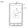
- FIG. 4 is a diagram of a screen 40 of the smartphone 1 as viewed from the front, and the broken-line rectangle 41 in the center of the image shows a focus area 41 that is set on the screen.
- the focus condition determination unit 14 reads out the line-of-sight estimation results (obtained during the most recent 1-second) from the record storage unit 17 and calculates the intersection between the line of sight and the screen for each line of sight.
- the relative positions of the camera 43 of the smartphone 1 and the screen 40 are already known, and therefore it is possible to geometrically calculate the intersection between the line of sight (straight line that passes through the position of the eye and is parallel with the line-of-sight direction) and the screen 40.
- Points 42 on the screen 40 in FIG. 4 are plotted as the intersections between the screen 40 and the most recent one-second-worth of lines of sight. With the example in FIG. 4 , all of the points 42 are in the focus area 41, and therefore it is determined that the current state is the "focused state”. If there is a line of sight that is shifted outside the focus area 41, it is determined that the current state is a "non-focused state".
- the position, size, and number of focus areas can be set arbitrarily.
- the end portion of the screen may be set to be a focus area
- focus areas may be set in four portions, namely the upper, lower, left, and right portions, of the screen
- the entire screen may be a focus area.
- the position, size, number, and the like of the focus area can also be changed dynamically according to the content displayed on the screen. For example, in the case of a browser or a document viewer, if a focus area is set at a position at which a document or an image is displayed, the reliability of determining the focus of the operator can be improved.
- step S33 If it is determined that the current state is the "non-focused state" by the focus condition determination unit 14 (NO in step S33), processing for determining the face direction or the like is skipped, and the processing ends. Accordingly, it is possible to prevent erroneous operation due to an unintended change in face direction, as shown in FIGS. 1B and 1C .
- step S34 the face direction condition determination unit 15 references the face direction estimation result stored in the record storage unit 17 and determines whether or not the face direction of the operator 2 satisfies a predetermined condition.
- the determination processing of the face direction condition determination unit 15 will be described next in detail with reference to FIGS. 5A and 5B .
- the xyz coordinate system shown in FIGS. 5A and 5B is a coordinate system that uses the screen of the smartphone 1 as a reference, in which the x axis is in the screen lateral direction, the y axis is in the screen lengthwise direction, and the z axis is in the normal line direction of the screen.
- FIG. 5A is a diagram of the smartphone 1 and the face of the operator 2 as viewed from the y direction
- FIG. 5B is a diagram as viewed from the x direction.
- a 3D vector 50 for the face direction is obtained as a result of the face direction estimation.
- An angle ⁇ formed by the vector 50 for the face direction and a reference direction vector 51, or in other words, a face direction shift amount ⁇ with respect to the reference direction is calculated by the face direction condition determination unit 15 for the x direction and the y direction.
- the shift amount in the x direction (angle about the y axis) is referred to as ⁇ x
- the shift amount in the y direction (angle about the x axis) is referred to as ⁇ y.
- the face direction condition determination unit 15 compares the shift amounts ⁇ x and ⁇ y and a threshold value ⁇ th.
- ⁇ x and ⁇ y are both smaller than the threshold value ⁇ th, that is, if the shift in the face direction is small, it is determined that a screen operation has not been input and the processing ends (NO in step S34).
- the threshold value ⁇ th is a parameter that can control the sensitivity of the face direction sensing, and can be set to any value that is greater than or equal to 0 degrees. In the case of being set to 0 degrees, the sensitivity is the highest, and even a slight shift of the face direction will be detected.
- references direction examples include (a) the line-of-sight direction of the operator 2, (b) the face direction in the case where it is assumed that the face of the operator 2 is directly facing the screen (i.e., the z direction is the reference direction), (c) the face direction at the point in time when the operator 2 starts focusing on the screen, and the like.
- Reference direction (a) has the advantage of being intuitive and easy to understand since the state in which the line-of-sight direction and the face direction match is neutral (no shift in face direction). For example, it is thought that reference direction (a) is best suited for operations on a device with a large screen (e.g., a display of a computer, a television apparatus, etc.).
- Reference direction (b) has the advantage of not requiring calculation such as line-of-sight detection in the determination of the reference direction since it is determined uniformly with respect to the screen. For example, it is thought that reference direction (b) is best suited for the case where the accuracy of line-of-sight detection is not very high, and for operations on devices with small screens (e.g., smartphones, tablet terminals, etc.). Note that the operator need not always be in an orientation in which he or she is directly facing the screen. For example, a case is possible in which the screen is viewed from an oblique angle, or only the line of sight is pointed toward the screen. In such a case, it is preferable to use reference direction (c).
- step S35 the screen operation unit 16 executes a predetermined screen operation.
- a predetermined screen operation For example, it is possible to operate the screen of an operating application program by transmitting a screen scrolling command or a page movement command using an OS (Operating System) or an API (Application Programming Interface) provided by the application program.
- OS Operating System
- API Application Programming Interface
- screen scrolling and page movement are screen operations, but other screen operations such as operation of a pointer, area designation, tab switching, and zooming in/out can be performed in this way too.
- the operator 2 can perform a screen operation.
- the flow in FIG. 3 is executed repeatedly, and therefore scrolling or page movement is executed continuously when the face direction is shifted while the focused state is maintained. Accordingly, with a simple operation of keeping the face direction shifted while an uninteresting page is displayed and returning the face direction to normal when an interesting page is displayed, it is possible to jump to an interesting page. Note that during that period, it is necessary to continue focusing on the screen, and since it is also necessary for the operator to visually confirm when to stop scrolling or page movement, it can be said that it is reasonable to use the focused state as a condition.
- the face direction condition determination unit 15 determines "whether or not the face direction of the operator has been shifted by a predetermined amount or more from the reference direction", but it is possible to use "whether or not the face direction of the operator remains shifted from the reference direction for a predetermined amount of time or longer" as a face direction condition. For example, if a screen operation is to be performed when the face direction remains shifted for 0.5 seconds or longer, the face direction condition determination unit 15 reads out the face direction estimation results (obtained during the most recent 0.5-seconds) from the record storage unit 17 and calculates the shift amount ⁇ for each face direction.
- step S35 If
- the predetermined amount of time in this case is also a parameter for controlling the sensitivity of the face direction sensing, and it is possible to set it to any value.
- the face direction condition determination unit 15 reads out the estimation results (obtained during the most recent 0.5 seconds) from the record storage unit 17 and calculates the shift amount ⁇ for each face direction. If
- the threshold value ⁇ th can be determined in advance, the user can set it in advance, and it can be determined dynamically based on the distance between the screen (or operation target device) and the face (operator).
- the face direction condition determination unit 15 may use "that the face direction point is shifted by a predetermined amount or more from the reference position set on the screen” as a face direction condition.
- the "face direction point” is a point obtained by projecting a predetermined point on the face of the operator onto the screen in a direction parallel to the face direction, and it can be calculated geometrically based on the position of the face, the face direction, the position of the screen, and the like. Examples of the "predetermined point on the face of the operator” include the central point of the face, the peak of the nose, the central point between the eyes (between the eyebrows), or the like.
- examples of the "reference position set on the screen” include (a) the intersection between the line of sight of the operator and the screen, (b) the face direction point of the face direction in the case where it is assumed that the face of the operator is directly facing the screen, (c) the face direction point of the face direction at the point in time when the operator starts focusing on the screen, (d) the central point of the screen, (e) the central point of the operation target area in the screen (an operation target window, etc.), or the like.
- the face direction condition may be "whether or not the face direction point of the operator remains shifted for a predetermined amount of time or more from the reference position", or "whether or not the face direction point of the operator remains shifted by a predetermined amount or more from the reference position for a predetermined amount of time or longer".
- the predetermined amount (threshold value) in this case is not an angle and may be expressed using the distance ⁇ Dth on the screen.
- the threshold value ⁇ Dth can also be determined in advance, the user can set it in advance, and it can be determined dynamically based on the distance between the screen (or operation target device) and the face (operator).
- the face direction condition determination unit 15 may use “that the face direction point is shifted to the outer side of the reference area set on the screen” or “that the face direction point remains shifted to the outer side of the reference area for a predetermined amount of time or longer” as the face direction condition.
- the position, size, shape, and the like of the "reference area set on the screen” can also be determined in advance, it can be set by the user, or it can be determined dynamically based on the distance between the screen (or the operation target device) and the face (operator).
- the position of the reference area may be determined using the above-described "reference position" as a reference (for example, setting the reference area such that it is centered about the reference position). Note that results that are substantially the same as changing the above-described threshold value ⁇ Dth according to the distance between the screen and the face can be obtained if the size of the reference area is fixed.
- the scrolling direction and the like can be changed according to whichever direction the face direction is shifted from the reference position or the reference area, which is similar to the first embodiment.
- Separate values on the x axis and the y axis can be set as the threshold values ⁇ th and ⁇ Dth. Also, separate values can be set for the + side and the-side of the x direction. Separate values can also be set for the + side and the-side of the y direction as well. As a benefit of setting separate values on the + side and the - side, a usage example is conceivable in which reduction of erroneous operation is achieved by reducing the threshold value in the page advancement direction so as to make it easier to scroll, or by increasing the threshold value in the page return direction so as to make it more difficult to scroll when browsing an e-book, for example. Similarly, it is possible to set separate values for the x axis and the y axis and to set separate values for the + side and the - side with respect to the "predetermined time" for face direction determination as well.
- the distance between the target device (screen) and the operator (face) is estimated based on the size of the face in the image, but it is also possible to measure or estimate the distance using another method. For example, it is possible to employ a method of imaging the face of the operator using a stereo camera and calculating the distance in the depth direction based on parallax information, a method of measuring the distance to the operator by providing another distance sensor in the target device, or the like.
- the x-direction shift amount ⁇ x and the y-direction shift amount ⁇ y may be calculated and evaluated separately also in the case of the modified example stated herein. Also, in order to increase the speed of the determination processing, it is preferable that the calculated shift amount is stored in the record storage unit 17 and the second and subsequent instances of calculation with respect to the same face direction are omitted.
- the screen operation unit 16 executes only one type of screen operation, but it is also possible to provide a variety of screen operations.
- the screen operation unit 16 may change the direction of scrolling or page movement according to the shift direction of the face direction of the operator 2.
- the screen operation unit 16 stores a screen operation table such as that shown in FIG. 6A and switches the screen operation that is to be executed according to the face direction shift amounts ⁇ x and ⁇ y calculated by the face direction condition determination unit 15. In the example shown in FIG.
- scrolling to the right is performed in the case where
- scrolling to the left is performed in the case where
- scrolling down is performed in the case where
- scrolling up is performed in the case where
- the screen operation unit 16 may change the speed or amount of scrolling or page movement according to the shift direction of the face direction of the operator 2. Specifically, the screen operation unit 16 stores a screen operation table such as that shown in FIG. 6B and switches the speed and amount of the screen execution that is to be executed according to the face direction shift amount ⁇ calculated by the face direction condition determination unit 15.
- scrolling speed is set to "high speed” in the case where
- the scrolling speed is set to "low speed” in the case where
- the change in the face direction is increased when high-speed scrolling is desired.
- switching is performed between two steps, but switching between three or more steps may be performed, or switching may be performed continuously (without steps). Also, it is preferable to allow adjustment of multiple types of screen operations in multiple steps using a combination of FIG. 6A and 6B .
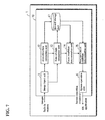
- FIG. 7 is a diagram schematically showing a functional configuration of a screen operation apparatus according to the second embodiment.
- a screen operation apparatus 70 is for enabling operation of a screen of the smartphone 1 by the operator 2 and is implemented as an operation input interface of the smartphone 1.
- the screen operation apparatus 70 has an image input unit 11, a face direction estimation unit 12, a line-of-sight estimation unit 13, a focus condition determination unit 14, a face movement condition determination unit 75, a screen operation unit 16, and a record storage unit 17.
- the configuration is the same as that of the first embodiment ( FIG. 2 ). Therefore, where the configurations are the same, the same reference numerals are used.
- FIG. 8 is a flowchart of main processing performed by the screen operation apparatus according to the second embodiment. This processing is repeatedly executed at a predetermined time interval while a screen that is to be the operation target is displayed on the smartphone 1 (for example, when a screen capable of scrolling and page movement is displayed). As described above, a few to around a dozen frames of images are processed per second in the present embodiment, and therefore the flow in FIG. 8 is executed at a few to around a dozen cycles per second.
- steps S80 to S82 is the same as that of steps S30 to S32 in the first embodiment ( FIG. 3 ).
- the focus condition determination unit 14 references the line-of-sight estimation result stored in the record storage unit 17 and determines whether or not the operator 2 is focusing on the screen (step S83). Similarly to the first embodiment, the predetermined time for determining focus is set to 1 second.
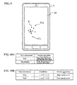
- FIG. 9 is a diagram of a screen 90 of the smartphone 1 as viewed from the front. Points 91 on the screen 90 are obtained by plotting, over the most recent 1-second, intersections between the lines of sight and the screen. In the present embodiment, if the line of sight of the operator 2 is on the screen 90 and the amount of change in the line of sight of the operator 2 remains less than a predetermined amount for 1 second or longer, it is determined that the current state is the "focused state". Specifically, the focus condition determination unit 14 calculates the intersections between the screen and lines of sight during the most recent 1 second, similar to the first embodiment.
- two points having the farthest distance between the two points are selected (points 91a and 91b in FIG. 9 ) from among the intersections, and if the distance between the two points is smaller than a predetermined threshold value, it can be determined that the current state is the "focused state". That is to say, unlike the first embodiment, it is determined that the current state is the focused state in the case where no focus area is provided in particular and the operator 2 continues to look somewhere on the screen 90. Rather than using the distance between two points, it is possible to evaluate whether or not the line of sight is being focused using the diameter of a circumscribed circle containing all of the points, the variance value of the coordinates of all of the points, or the like, for example. Note that in the present embodiment as well, the determination method of the first embodiment (method using focus area) may be employed, and conversely, it is also possible to use the determination method of the present embodiment in the first embodiment.
- step S83 If it is determined that the current state is the "non-focused state" by the focus condition determination unit 14 (NO in step S83), processing for determining face movement is skipped and the processing ends. Accordingly, erroneous operation due to unintended face movement can be prevented.
- step S83 the procedure moves to the face movement condition determination in step S34.
- step S84 the face movement condition determination unit 75 references the face direction estimation result stored in the record storage unit 17 and determines whether or not the face of the operator 2 has performed a predetermined movement.
- Examples of the predetermined movement include (1) a movement of changing the face direction or the face orientation, (2) a movement of blinking or closing the eyes, (3) a movement of creating a predetermined expression, or the like.
- the movement of changing the face direction is, for example, a nodding movement (movement of shaking head up and down; movement of rotation about the x axis), a headshake movement (movement of shaking head left and right; movement of rotation about the y axis), or the like.
- a vector for the face directions of the most recent several frames is read out from the record storage unit 17 and the change in the orientation of the vector is evaluated. Thus, it is possible to detect a nodding movement or a headshake movement.
- a movement of changing the orientation of the face is, for example, a movement of tilting the head (movement of inclining the head portion left or right; movement of rotation about the z axis), or the like. It is also possible to perform detection using the fitting result of the 3D face model in the face direction estimation, for example.
- a movement of blinking or closing the eyes can be detected by calculating the degree of opening the eyes based on the face direction estimation results or the line-of-sight estimation results and evaluating the change in the degree of opening the eyes of the most recent several frames. It is possible to detect the movement of both eyes, and it is possible to detect the movement of only one eye.
- a movement of creating an expression is a movement of a facial part (eyes, nose, mouth, etc.), and expression such as a smile, opening or closing the mouth, or a movement of frowning, may be used. It is also possible to perform detection using the fitting result (positional relationship between facial parts) of the 3D face model in the face direction estimation, or the like, for example. Note that many algorithms for estimating face direction, face orientation, blinking, eye-shutting, expressions, and the like based on an image have been proposed, and any algorithm may be employed.
- step S84 If it is determined that the face of the operator 2 has performed a predetermined movement (YES in step S84), the procedure moves to step S85. On the other hand, if a predetermined movement is not detected, it is determined that input of a screen operation was not performed, and the processing ends (NO in step S84).
- step S85 the screen operation unit 16 executes a predetermined screen operation.
- the processing of step S85 is similar to that of the first embodiment.
- the operator 2 can perform a screen operation.
- the flow in FIG. 8 is executed repeatedly, and therefore scrolling or page movement is executed continuously when the face movement is repeated while the focused state is maintained. Accordingly, with a simple operation of continuing to move the face while an uninteresting page is displayed and stopping the movement when an interesting page is displayed, it is possible to easily jump to an interesting page. Note that during that period, it is necessary to continue focusing on the screen, and since it is also necessary for the operator to visually confirm when to stop scrolling or page movement, it can be said that it is reasonable to use the focused state as a condition.
- the screen operation unit 16 may change the direction of scrolling or page movement according to the type of movement of the face of the operator 2. Specifically, the screen operation unit 16 stores a screen operation table such as that shown in FIG. 10A and switches the screen operation that is to be executed according to the movement of the face detected by the face movement condition determination unit 75. For example in FIG. 10A , page movement in the advancing direction is executed with a nodding movement, and page movement in the reverse direction is executed with a head shaking movement. Accordingly, various screen operations can be performed.
- the screen operation unit 16 may change the speed or amount of scrolling or page movement according to the size of movement or the speed of movement of the face of the operator 2. Specifically, the screen operation unit 16 stores a screen operation table such as that shown in FIG. 10B and switches the speed or the amount of the screen operation that is to be executed, according to the size of movement or the speed of movement of the face detected by the face movement condition determination unit 75. For example in FIG. 10B , scrolling speed is set to "high speed" in the case where the angle ⁇ of the nodding movement is
- the line-of-sight estimation unit 13 outputs a line-of-sight estimation result obtained by performing estimation based on one image, but a representative value for a plurality of lines of sight (e.g., mean, mode, or median value, or the like) obtained based on a plurality of images (e.g., a few to around a dozen frames) that were obtained successively may be output as the line-of-sight estimation result.
- a representative value for a plurality of sight e.g., mean, mode, or median value, or the like
- a plurality of images e.g., a few to around a dozen frames
- a person's line-of-sight direction can fluctuate in short intervals with sudden significant changes.
- the line of sight is unstable and there is a risk that the current state will never be determined as being the focused state, even if only instantaneous values for the line-of-sight direction are evaluated.
- a representative value for a plurality of lines of sight it is possible to mitigate or remove noise such as fluctuation or rapid change in the line-of-sight direction, and to achieve an improvement in the accuracy of the focus determination. Note that it is also preferable to apply similar processing to the face direction estimation.
- the screen operation apparatus may also include a notification unit for notifying the operator of the fact that "focusing" has been determined. Accordingly, the operator can understand that the focus condition, which is a first condition, is satisfied and that he or she is in a state of being able to input a screen operation by means of face direction or face movement, and thus an improvement in usability is achieved.
- a method such as displaying an icon or a predetermined graphic on the screen, displaying a message, illuminating an LED, notifying by means of noise, notifying by means of vibration, changing the color or thickness of the screen edge or the border of the window that is to be operated, or changing the size of the window in the case where the operation target is a window, can be employed, for example, as the notification method.
- a screen operation of a smartphone was illustrated as an example in the above embodiments, but an embodiment of the present invention can be favorably applied to any electronic device with a screen, such as, for example, a personal computer, a mobile phone, a tablet terminal (slate terminal), a portable information terminal, a game apparatus, a television apparatus, and an image capturing apparatus.
- a personal computer such as, for example, a personal computer, a mobile phone, a tablet terminal (slate terminal), a portable information terminal, a game apparatus, a television apparatus, and an image capturing apparatus.
- a configuration in which a screen is operated using a combination of the line of sight and the face direction or a combination of the line of sight and a movement of the face.
- the target of operation may be an entire screen (or content displayed thereon), and it may be a portion of a screen (e.g., content displayed in a window or sub-screen).
- a screen operation apparatus for enabling operation of a screen by an operator, the screen operation apparatus including: an image input unit configured to obtain images of a face of the operator at a predetermined time interval; a focus condition determination unit configured to, using the images obtained by the image input unit, determine whether or not the operator is focusing on the screen; a face direction condition determination unit configured to, using the images obtained by the image input unit, determine whether or not the face direction of the operator satisfies a predetermined condition; and a screen operation unit configured to execute a predetermined screen operation in the case where the face direction condition determination unit determines that the face direction of the operator satisfies a predetermined condition while the focus condition determination unit determines that the operator is focusing on the screen.
- information regarding the line of sight can also be used in addition to the face direction. That is to say, screen operation by means of face direction is restricted such that it can only be performed while the operator is focusing on the screen. Accordingly, it is possible to suppress erroneous operation due to unintended changes in face direction, and operation input with superior operability and usability can be realized.
- Examples of the predetermined condition include (1) that the face direction of the operator is shifted by a predetermined amount or more from a reference direction, (2) that the face direction point (which is a point obtained by projecting a predetermined point on the face of the operator onto the screen in a direction parallel to the face direction) of the operator remains shifted from the reference position for a predetermined amount of time or longer, and (3) that the face orientation of the operator remains shifted by a predetermined amount or more from a reference direction for a predetermined amount of time or longer.
- Examples of the reference direction include (a) the line-of-sight direction of the operator, (b) the face direction in the case where it is assumed that the face of the operator is directly facing the screen, and (c) the face direction at a point in time when the operator starts focusing on the screen.
- the predetermined condition may be (1) that the face direction point is shifted from the reference position set on the screen by a predetermined amount or more, (2) that the face direction point of the operator remains shifted from the reference position for a predetermined amount of time or longer, or (3) that the face direction point of the operator remains shifted by a predetermined amount or more from the reference position for a predetermined amount of time or longer.
- the "predetermined point on the face of the operator” include the central point of the face, the peak of the nose, and the central point between the eyes (between the eyebrows).
- examples of the "reference position set on the screen” include (a) the intersection between the line-of-sight of the operator and the screen, (b) the face direction point of the face direction in the case where it is assumed that the face of the operator is directly facing the screen, (c) the face direction point of the face direction at a point in time when the operator starts focusing on the screen, (d) the central point of the screen, and (e) the central point of the operation target area on the screen.
- the predetermined condition may be (1) that a face direction point, which is a point obtained by projecting a predetermined point on the face of the operator onto the screen in a direction parallel to the face direction, is shifted to the outer side of a reference area set on the screen, or (2) that the face direction point of the operator remains shifted to the outer side of the reference area for a predetermined amount of time or longer.
- the position, size, shape, and the like of the "reference area set on the screen" can be set arbitrarily.
- the position of the reference area may be determined using the above-described "reference position" as a reference.
- scrolling, page movement, or the like is preferable as the predetermined screen operation.
- the movements of scrolling and page movement are intuitively linked to the action of shifting the face direction (e.g., the actions of facing up, down, to the left, or to the right).
- the screen operation unit changes the direction of scrolling or page movement in accordance with the direction in which the face direction of the operator is shifted. For example, it is sufficient that scrolling to the right or page movement to the right is executed when the face is turned to the right, and scrolling or page movement in the opposite direction (left direction) is executed when the face is turned to the left. According to this, an intuitive operability is obtained.
- the screen operation unit may change the speed or amount of scrolling or page movement in accordance with the amount by which the face direction of the operator is shifted. For example, it is preferable that the scrolling speed (amount) or the page movement speed (amount) is increased in a step-wise manner or continuously as the shift amount increases. Accordingly, the scrolling speed (amount) or the page movement speed (amount) can be adjusted with an intuitive action.
- a screen operation apparatus is a screen operation apparatus for enabling operation of a screen by an operator, the screen operation apparatus including: an image input unit configured to obtain images of a face of the operator at a predetermined time interval; a focus condition determination unit configured to, using the images obtained by the image input unit, determine whether or not the operator is focusing on the screen; a movement condition determination unit configured to, using the images obtained by the image input unit, determine a movement of the face of the operator; and a screen operation unit configured to execute a predetermined screen operation in the case where the movement condition determination unit determines that the face of the operator has performed a predetermined movement while the focus condition determination unit determines that the operator is focusing on the screen.
- information regarding the line of sight can also be used in addition to the movement of the face. That is to say, screen operation by means of movement of the face is restricted such that it can be performed only while the operator is focusing on the screen. Accordingly, it is possible to suppress erroneous operation by means of unintended face movement, and operation input with superior operability and usability can be realized.
- Examples of the predetermined movement include (1) a movement of changing the face direction or face orientation, (2) a movement of blinking or closing an eye, and (3) a movement of creating a predetermined expression, or the like.
- a movement of changing the face direction is, for example, a nodding movement (movement of shaking head up and down), a headshake movement (movement of shaking head left and right), or the like.
- a movement of changing the face orientation is, for example, a movement of tilting the head (movement of inclining the head portion left or right), or the like.
- the movement of blinking or closing an eye may be performed with both eyes or one eye.
- a movement of creating an expression is a movement of a facial part (eyes, nose, mouth), and anything may be used, such as a smile, opening and closing the mouth, or frowning.
- scrolling, page movement, or the like is preferable as the predetermined screen operation.
- the screen operation unit changes the direction of scrolling or page movement in accordance with the type of movement of the face of the operator. For example, it is conceivable to perform scrolling or page movement in the advancing direction using a nodding movement, to perform scrolling or page advancement in the reverse direction using a headshake movement, and the like. Accordingly, various screen operations can be performed.
- the screen operation unit may change the speed or amount of scrolling or page movement in accordance with the size of movement or the speed of movement of the face of the operator. For example, when using a headshake movement, it is preferable that the scrolling speed (amount) or page movement speed (amount) is increased in a step-wise manner or continuously as the angle or speed of the headshake increases. Accordingly, the scrolling speed (amount) or the page movement speed (amount) can be adjusted with a highly intuitive action.
- the focus condition determination unit determines that the operator is focusing on the screen in the case where a state in which the lines of sight of the operator are in a predetermined portion of the screen continues for a predetermined amount of time or longer. In other words, it is determined that the current state is a focused state if the operator continues to look at a predetermined portion set on the screen (also referred to as the focus area).
- the focus condition determination unit may determine that the operator is focusing on the screen in the case where a state in which the lines of sight of the operator intersect the screen and the amount of change in the lines of sight of the operator is less than a predetermined value continues for a predetermined amount of time or longer. In other words, it is determined that the current state is the focused state in the case where no focus area is provided in particular and the operator continues to look somewhere on the screen. This kind of method is easier to use in some cases, depending on the content displayed on the screen.
- the line-of-sight estimation unit obtains a plurality of lines of sight of the operator from a plurality of images obtained successively by the image input unit and outputs a representative value for the plurality of lines of sight obtained from the plurality of images as a line-of-sight estimation result.
- a representative value for the plurality of lines of sight e.g., mean, mode, median value, or the like
- a notification unit configured to notify the operator of a state in which the focus condition determination unit has determined that the operator is focusing on the screen. According to this, the operator can know if it is possible to input screen operations and an improvement in usability is achieved.
- embodiments of the present invention can be understood as being a screen operation apparatus or an electronic device including the screen operation apparatus, which has at least a portion of the above-described configuration.
- embodiments of the present invention can also be understood as being a screen operation method, a program for causing a computer to execute the steps of the method, or a computer-readable storage medium non-transitorily storing the program, that includes at least a portion of the above-described processing.
- Examples of electronic devices include a personal computer, a mobile phone, a smart phone, a tablet terminal (slate terminal), a portable information terminal, a game apparatus, a television apparatus, an image capturing apparatus.
- Embodiments of the present invention can be configured by combining the above-described configurations and processes, as long as no technical conflicts are generated.
- hands-free, non-contact operation of a screen can be performed and there is less operational burden and operation is easier compared to conventional line-of-sight input.
Landscapes
- Engineering & Computer Science (AREA)
- General Engineering & Computer Science (AREA)
- Theoretical Computer Science (AREA)
- Human Computer Interaction (AREA)
- Physics & Mathematics (AREA)
- General Physics & Mathematics (AREA)
- User Interface Of Digital Computer (AREA)
- Image Processing (AREA)
- Image Analysis (AREA)
Applications Claiming Priority (1)
| Application Number | Priority Date | Filing Date | Title |
|---|---|---|---|
| JP2013223646A JP2015087824A (ja) | 2013-10-28 | 2013-10-28 | 画面操作装置および画面操作方法 |
Publications (2)
| Publication Number | Publication Date |
|---|---|
| EP2866123A2 true EP2866123A2 (fr) | 2015-04-29 |
| EP2866123A3 EP2866123A3 (fr) | 2015-08-19 |
Family
ID=51625804
Family Applications (1)
| Application Number | Title | Priority Date | Filing Date |
|---|---|---|---|
| EP14185303.6A Withdrawn EP2866123A3 (fr) | 2013-10-28 | 2014-09-18 | Appareil de fonctionnement d'écran et procédé de fonctionnement de l'écran |
Country Status (5)
| Country | Link |
|---|---|
| US (1) | US20150116206A1 (fr) |
| EP (1) | EP2866123A3 (fr) |
| JP (1) | JP2015087824A (fr) |
| KR (1) | KR101663452B1 (fr) |
| CN (1) | CN104598019A (fr) |
Cited By (1)
| Publication number | Priority date | Publication date | Assignee | Title |
|---|---|---|---|---|
| US11333902B2 (en) * | 2017-12-12 | 2022-05-17 | RaayonNova LLC | Smart contact lens with embedded display and image focusing system |
Families Citing this family (34)
| Publication number | Priority date | Publication date | Assignee | Title |
|---|---|---|---|---|
| JP2015056141A (ja) | 2013-09-13 | 2015-03-23 | ソニー株式会社 | 情報処理装置、および情報処理方法 |
| FR3018119B1 (fr) * | 2014-02-28 | 2017-07-07 | Thales Sa | Systeme de visualisation de casque comportant des moyens d'affichage et de gestion de documentation |
| CN104834382B (zh) * | 2015-05-21 | 2018-03-02 | 上海斐讯数据通信技术有限公司 | 移动终端应用程序响应系统及方法 |
| DE102015213769A1 (de) * | 2015-07-22 | 2017-01-26 | Robert Bosch Gmbh | Verfahren und Vorrichtung zum Prädizieren einer Blickrichtung eines Fahrzeuginsassen |
| JP6433862B2 (ja) * | 2015-08-18 | 2018-12-05 | 株式会社コロプラ | ヘッドマウントディスプレイシステム制御プログラム、コンピュータ及び方法 |
| JP6398938B2 (ja) * | 2015-09-30 | 2018-10-03 | ブラザー工業株式会社 | 投影制御装置、及びプログラム |
| JP6637757B2 (ja) * | 2015-12-22 | 2020-01-29 | 株式会社トプコン | 眼調節機能支援システム |
| JP6897820B2 (ja) * | 2016-06-28 | 2021-07-07 | 富士フイルムビジネスイノベーション株式会社 | 情報処理装置、情報処理システムおよび画像形成装置 |
| JP6282696B2 (ja) | 2016-07-27 | 2018-02-21 | 京セラ株式会社 | 電子機器及び制御方法 |
| JP2018036476A (ja) * | 2016-08-31 | 2018-03-08 | アイシン・エィ・ダブリュ株式会社 | スクロール制御システムおよびスクロール制御プログラム |
| JP6169298B1 (ja) * | 2017-02-16 | 2017-07-26 | 京セラ株式会社 | 電子機器及び制御方法 |
| CN107390864B (zh) * | 2017-06-19 | 2021-05-04 | 广东数相智能科技有限公司 | 基于眼球轨迹追踪的网络调研方法、电子设备及存储介质 |
| JP6387154B2 (ja) * | 2017-06-27 | 2018-09-05 | 京セラ株式会社 | 電子機器及び制御方法 |
| JP6922686B2 (ja) | 2017-11-20 | 2021-08-18 | トヨタ自動車株式会社 | 操作装置 |
| JP2019135601A (ja) * | 2018-02-05 | 2019-08-15 | Kddi株式会社 | 入力制御装置、入力制御方法及びプログラム |
| EP3572910B1 (fr) | 2018-05-21 | 2021-11-24 | Vestel Elektronik Sanayi ve Ticaret A.S. | Procédé, système et programme informatique pour commander à distance un dispositif d'affichage au moyen de gestes de la tête |
| CN108888487A (zh) * | 2018-05-22 | 2018-11-27 | 深圳奥比中光科技有限公司 | 一种眼球训练系统及方法 |
| CN108829242A (zh) * | 2018-05-22 | 2018-11-16 | 深圳奥比中光科技有限公司 | 智能终端及其非触控式操作方法 |
| JP6387204B2 (ja) * | 2018-05-30 | 2018-09-05 | 京セラ株式会社 | 電子機器及び制御方法 |
| JP2020052190A (ja) * | 2018-09-26 | 2020-04-02 | いすゞ自動車株式会社 | 表示制御装置及び表示制御方法 |
| JP2020052188A (ja) * | 2018-09-26 | 2020-04-02 | いすゞ自動車株式会社 | 表示制御装置及び表示制御方法 |
| JP2020052189A (ja) * | 2018-09-26 | 2020-04-02 | いすゞ自動車株式会社 | 表示制御装置及び表示制御方法 |
| JP2020052191A (ja) * | 2018-09-26 | 2020-04-02 | いすゞ自動車株式会社 | 表示制御装置及び表示制御方法 |
| KR102233481B1 (ko) * | 2018-10-18 | 2021-03-29 | 주식회사 토비스 | 화면 제어 방법 및 표시 장치 |
| JP6726319B2 (ja) * | 2018-11-12 | 2020-07-22 | 知行 宍戸 | 補助ペダルシステム |
| JP2020107187A (ja) * | 2018-12-28 | 2020-07-09 | いすゞ自動車株式会社 | 表示制御装置及び表示制御方法 |
| CN110333779B (zh) * | 2019-06-04 | 2022-06-21 | Oppo广东移动通信有限公司 | 控制方法、终端和存储介质 |
| CN110287906A (zh) * | 2019-06-26 | 2019-09-27 | 四川长虹电器股份有限公司 | 基于图像视频检测人“玩手机”的方法及系统 |
| CN110363133B (zh) * | 2019-07-10 | 2021-06-01 | 广州市百果园信息技术有限公司 | 一种视线检测和视频处理的方法、装置、设备和存储介质 |
| JP6757841B2 (ja) * | 2019-11-08 | 2020-09-23 | 株式会社トプコン | 眼調節機能支援システム |
| CN112541400B (zh) * | 2020-11-20 | 2024-06-21 | 小米科技(武汉)有限公司 | 基于视线估计的行为识别方法及装置、电子设备、存储介质 |
| CN112434595B (zh) | 2020-11-20 | 2024-07-19 | 小米科技(武汉)有限公司 | 行为识别方法及装置、电子设备、存储介质 |
| JP7802561B2 (ja) * | 2022-02-08 | 2026-01-20 | キヤノン株式会社 | 電子機器、電子機器の制御方法、プログラム、および記録媒体 |
| CN115297351B (zh) * | 2022-08-03 | 2023-11-17 | 抖音视界有限公司 | 一种全景视频播放方法、装置、存储介质及电子设备 |
Citations (1)
| Publication number | Priority date | Publication date | Assignee | Title |
|---|---|---|---|---|
| JP2009227246A (ja) | 2008-03-25 | 2009-10-08 | Denso Corp | 車両用操作入力装置 |
Family Cites Families (18)
| Publication number | Priority date | Publication date | Assignee | Title |
|---|---|---|---|---|
| JPH07244556A (ja) * | 1994-03-04 | 1995-09-19 | Hitachi Ltd | 情報端末 |
| JP2000163196A (ja) * | 1998-09-25 | 2000-06-16 | Sanyo Electric Co Ltd | ジェスチャ認識装置及びジェスチャ認識機能を有する指示認識装置 |
| US7889244B2 (en) * | 2005-12-27 | 2011-02-15 | Panasonic Corporation | Image processing apparatus |
| JP5228305B2 (ja) * | 2006-09-08 | 2013-07-03 | ソニー株式会社 | 表示装置、表示方法 |
| JP2008186247A (ja) * | 2007-01-30 | 2008-08-14 | Oki Electric Ind Co Ltd | 顔向き検出装置および顔向き検出方法 |
| JP5433935B2 (ja) * | 2007-07-24 | 2014-03-05 | 日本電気株式会社 | 画面表示制御方法、画面表示制御方式、電子機器及びプログラム |
| JP4884417B2 (ja) * | 2008-04-01 | 2012-02-29 | 富士フイルム株式会社 | 携帯型電子装置及びその制御方法 |
| TWI450178B (zh) * | 2008-04-25 | 2014-08-21 | Wistron Corp | 驅動電子裝置顯示頁面捲動之方法與裝置 |
| EP2306891A1 (fr) * | 2008-07-08 | 2011-04-13 | IT University of Copenhagen | Procédé de suivi du regard |
| EP2395420B1 (fr) * | 2009-02-05 | 2018-07-11 | Panasonic Intellectual Property Corporation of America | Dispositif et procédé d'affichage d'informations |
| JP5423183B2 (ja) * | 2009-07-03 | 2014-02-19 | ソニー株式会社 | 表示制御装置および表示制御方法 |
| US8762846B2 (en) * | 2009-11-16 | 2014-06-24 | Broadcom Corporation | Method and system for adaptive viewport for a mobile device based on viewing angle |
| CN101866215B (zh) * | 2010-04-20 | 2013-10-16 | 复旦大学 | 在视频监控中采用视线跟踪的人机交互装置和方法 |
| EP2573650A1 (fr) * | 2010-05-20 | 2013-03-27 | Nec Corporation | Terminal portatif de traitement d'informations |
| JP2011243141A (ja) * | 2010-05-21 | 2011-12-01 | Nec System Technologies Ltd | 操作情報処理装置、方法及びプログラム |
| JP5323770B2 (ja) * | 2010-06-30 | 2013-10-23 | 日本放送協会 | ユーザ指示取得装置、ユーザ指示取得プログラムおよびテレビ受像機 |
| CN102043952B (zh) * | 2010-12-31 | 2012-09-19 | 山东大学 | 一种基于双光源的视线跟踪方法 |
| US8643680B2 (en) * | 2011-04-08 | 2014-02-04 | Amazon Technologies, Inc. | Gaze-based content display |
-
2013
- 2013-10-28 JP JP2013223646A patent/JP2015087824A/ja active Pending
-
2014
- 2014-09-16 KR KR1020140122452A patent/KR101663452B1/ko active Active
- 2014-09-18 EP EP14185303.6A patent/EP2866123A3/fr not_active Withdrawn
- 2014-09-22 US US14/492,499 patent/US20150116206A1/en not_active Abandoned
- 2014-09-30 CN CN201410520370.8A patent/CN104598019A/zh active Pending
Patent Citations (1)
| Publication number | Priority date | Publication date | Assignee | Title |
|---|---|---|---|---|
| JP2009227246A (ja) | 2008-03-25 | 2009-10-08 | Denso Corp | 車両用操作入力装置 |
Non-Patent Citations (3)
| Title |
|---|
| TAKEHIKO OHNO; NAOKI MUKAWA; ATSUSHI YOSHIKAWA: "An Eyeball Model Based Eye Tracking Method", PROCEEDINGS OF THE 8TH SYMPOSIUM ON SENSING VIA IMAGE INFORMATION, 2002, pages 307 - 312 |
| YASUHIRO ONO; TAKAHIRO OKABE; YOICHI SATO: "Gaze Estimation from Low Resolution Images Insensitive to Segmentation Error", PROCEEDINGS OF THE MEETING ON IMAGE RECOGNITION AND UNDERSTANDING (MIRU 2005, 2005, pages 96 - 103 |
| YUKARI NAKAMATSU; TETSUYA TAKIGUCHI; YASUO ARIKI: "Gaze Estimation Using 3D Active Appearance Models", PROCEEDINGS OF THE MEETING ON IMAGE RECOGNITION AND UNDERSTANDING (MIRU, 2011, pages 572 - 579 |
Cited By (1)
| Publication number | Priority date | Publication date | Assignee | Title |
|---|---|---|---|---|
| US11333902B2 (en) * | 2017-12-12 | 2022-05-17 | RaayonNova LLC | Smart contact lens with embedded display and image focusing system |
Also Published As
| Publication number | Publication date |
|---|---|
| KR20150048623A (ko) | 2015-05-07 |
| CN104598019A (zh) | 2015-05-06 |
| US20150116206A1 (en) | 2015-04-30 |
| EP2866123A3 (fr) | 2015-08-19 |
| KR101663452B1 (ko) | 2016-10-07 |
| JP2015087824A (ja) | 2015-05-07 |
Similar Documents
| Publication | Publication Date | Title |
|---|---|---|
| EP2866123A2 (fr) | Appareil de fonctionnement d'écran et procédé de fonctionnement de l'écran | |
| JP6551502B2 (ja) | ヘッドマウントディスプレイ、情報処理方法、及びプログラム | |
| CN105593787B (zh) | 用于与数字设备交互的直接指向检测的系统和方法 | |
| US10203764B2 (en) | Systems and methods for triggering actions based on touch-free gesture detection | |
| US9378581B2 (en) | Approaches for highlighting active interface elements | |
| JP6008309B2 (ja) | 電子ミラー装置 | |
| EP2864932B1 (fr) | Positionnement d'extrémité de doigt pour une entrée de geste | |
| JP6057396B2 (ja) | 3次元ユーザインタフェース装置及び3次元操作処理方法 | |
| US10642348B2 (en) | Display device and image display method | |
| US9342925B2 (en) | Information processing apparatus, information processing method, and program | |
| EP3144775B1 (fr) | Système de traitement d'informations et procédé de traitement d'informations | |
| JP2016194799A (ja) | 画像解析装置及び画像解析方法 | |
| JP2017102603A (ja) | 画像処理装置、画像処理方法および画像処理プログラム | |
| WO2014106219A1 (fr) | Interface centrée utilisateur pour une interaction avec un écran de visualisation qui reconnaît les intentions d'un utilisateur | |
| US9400575B1 (en) | Finger detection for element selection | |
| WO2024131694A1 (fr) | Procédés et systèmes d'interaction assistée par le regard | |
| US9898183B1 (en) | Motions for object rendering and selection | |
| US20160026244A1 (en) | Gui device | |
| US10082936B1 (en) | Handedness determinations for electronic devices | |
| CN110494915B (zh) | 电子装置及其控制方法和计算机可读介质 | |
| US12314470B2 (en) | Information processing system used in cross reality | |
| JP5558899B2 (ja) | 情報処理装置、その処理方法及びプログラム | |
| JP2006243784A (ja) | ポインティングシステム及びポインティング方法 | |
| JP6514416B2 (ja) | 画像表示装置、画像表示方法、及び画像表示プログラム | |
| Schmieder et al. | Thumbs up: 3D gesture input on mobile phones using the front facing camera |
Legal Events
| Date | Code | Title | Description |
|---|---|---|---|
| PUAI | Public reference made under article 153(3) epc to a published international application that has entered the european phase |
Free format text: ORIGINAL CODE: 0009012 |
|
| 17P | Request for examination filed |
Effective date: 20140918 |
|
| AK | Designated contracting states |
Kind code of ref document: A2 Designated state(s): AL AT BE BG CH CY CZ DE DK EE ES FI FR GB GR HR HU IE IS IT LI LT LU LV MC MK MT NL NO PL PT RO RS SE SI SK SM TR |
|
| AX | Request for extension of the european patent |
Extension state: BA ME |
|
| PUAL | Search report despatched |
Free format text: ORIGINAL CODE: 0009013 |
|
| AK | Designated contracting states |
Kind code of ref document: A3 Designated state(s): AL AT BE BG CH CY CZ DE DK EE ES FI FR GB GR HR HU IE IS IT LI LT LU LV MC MK MT NL NO PL PT RO RS SE SI SK SM TR |
|
| AX | Request for extension of the european patent |
Extension state: BA ME |
|
| RIC1 | Information provided on ipc code assigned before grant |
Ipc: G06F 3/01 20060101AFI20150710BHEP |
|
| R17P | Request for examination filed (corrected) |
Effective date: 20160107 |
|
| RBV | Designated contracting states (corrected) |
Designated state(s): AL AT BE BG CH CY CZ DE DK EE ES FI FR GB GR HR HU IE IS IT LI LT LU LV MC MK MT NL NO PL PT RO RS SE SI SK SM TR |
|
| STAA | Information on the status of an ep patent application or granted ep patent |
Free format text: STATUS: EXAMINATION IS IN PROGRESS |
|
| 17Q | First examination report despatched |
Effective date: 20171005 |
|
| STAA | Information on the status of an ep patent application or granted ep patent |
Free format text: STATUS: THE APPLICATION HAS BEEN WITHDRAWN |
|
| 18W | Application withdrawn |
Effective date: 20180213 |