EP2866266A1 - Module de cellule solaire - Google Patents
Module de cellule solaire Download PDFInfo
- Publication number
- EP2866266A1 EP2866266A1 EP13807231.9A EP13807231A EP2866266A1 EP 2866266 A1 EP2866266 A1 EP 2866266A1 EP 13807231 A EP13807231 A EP 13807231A EP 2866266 A1 EP2866266 A1 EP 2866266A1
- Authority
- EP
- European Patent Office
- Prior art keywords
- solar cell
- sealing portion
- cell module
- porous body
- nonwoven fabric
- Prior art date
- Legal status (The legal status is an assumption and is not a legal conclusion. Google has not performed a legal analysis and makes no representation as to the accuracy of the status listed.)
- Withdrawn
Links
- 238000007789 sealing Methods 0.000 claims abstract description 135
- 239000003566 sealing material Substances 0.000 claims description 94
- 239000004745 nonwoven fabric Substances 0.000 claims description 53
- 239000000835 fiber Substances 0.000 claims description 52
- 239000004744 fabric Substances 0.000 claims description 21
- 230000001681 protective effect Effects 0.000 claims description 11
- -1 polyethylene terephthalate Polymers 0.000 claims description 7
- 229920000139 polyethylene terephthalate Polymers 0.000 claims description 3
- 239000005020 polyethylene terephthalate Substances 0.000 claims description 3
- 229920000098 polyolefin Polymers 0.000 claims description 3
- 229920001577 copolymer Polymers 0.000 claims description 2
- 229920000554 ionomer Polymers 0.000 claims description 2
- 229920002037 poly(vinyl butyral) polymer Polymers 0.000 claims description 2
- 229920005672 polyolefin resin Polymers 0.000 claims description 2
- 229920002050 silicone resin Polymers 0.000 claims description 2
- 229920002803 thermoplastic polyurethane Polymers 0.000 claims description 2
- 238000003475 lamination Methods 0.000 abstract description 34
- 238000002834 transmittance Methods 0.000 abstract description 6
- 230000000052 comparative effect Effects 0.000 description 17
- 229920005989 resin Polymers 0.000 description 17
- 239000011347 resin Substances 0.000 description 17
- 239000005038 ethylene vinyl acetate Substances 0.000 description 16
- 239000000463 material Substances 0.000 description 16
- 229920001200 poly(ethylene-vinyl acetate) Polymers 0.000 description 16
- 238000012360 testing method Methods 0.000 description 16
- 229920000728 polyester Polymers 0.000 description 13
- 239000011800 void material Substances 0.000 description 13
- 238000011156 evaluation Methods 0.000 description 11
- 238000000465 moulding Methods 0.000 description 11
- GWEVSGVZZGPLCZ-UHFFFAOYSA-N Titan oxide Chemical compound O=[Ti]=O GWEVSGVZZGPLCZ-UHFFFAOYSA-N 0.000 description 10
- 238000000034 method Methods 0.000 description 10
- 230000008595 infiltration Effects 0.000 description 6
- 238000001764 infiltration Methods 0.000 description 6
- 230000008569 process Effects 0.000 description 6
- 239000004698 Polyethylene Substances 0.000 description 5
- 229920000573 polyethylene Polymers 0.000 description 5
- 238000006243 chemical reaction Methods 0.000 description 4
- 239000010408 film Substances 0.000 description 4
- 238000010030 laminating Methods 0.000 description 4
- 239000004750 melt-blown nonwoven Substances 0.000 description 4
- 238000010248 power generation Methods 0.000 description 4
- 239000004408 titanium dioxide Substances 0.000 description 4
- 229910052782 aluminium Inorganic materials 0.000 description 3
- XAGFODPZIPBFFR-UHFFFAOYSA-N aluminium Chemical compound [Al] XAGFODPZIPBFFR-UHFFFAOYSA-N 0.000 description 3
- 230000006866 deterioration Effects 0.000 description 3
- 239000011521 glass Substances 0.000 description 3
- 238000005259 measurement Methods 0.000 description 3
- 239000002861 polymer material Substances 0.000 description 3
- 239000007787 solid Substances 0.000 description 3
- 238000011179 visual inspection Methods 0.000 description 3
- JBRZTFJDHDCESZ-UHFFFAOYSA-N AsGa Chemical compound [As]#[Ga] JBRZTFJDHDCESZ-UHFFFAOYSA-N 0.000 description 2
- YCKRFDGAMUMZLT-UHFFFAOYSA-N Fluorine atom Chemical compound [F] YCKRFDGAMUMZLT-UHFFFAOYSA-N 0.000 description 2
- XUIMIQQOPSSXEZ-UHFFFAOYSA-N Silicon Chemical compound [Si] XUIMIQQOPSSXEZ-UHFFFAOYSA-N 0.000 description 2
- 239000000654 additive Substances 0.000 description 2
- 230000000996 additive effect Effects 0.000 description 2
- 239000003963 antioxidant agent Substances 0.000 description 2
- 230000003078 antioxidant effect Effects 0.000 description 2
- 239000003795 chemical substances by application Substances 0.000 description 2
- UIPVMGDJUWUZEI-UHFFFAOYSA-N copper;selanylideneindium Chemical compound [Cu].[In]=[Se] UIPVMGDJUWUZEI-UHFFFAOYSA-N 0.000 description 2
- 238000006073 displacement reaction Methods 0.000 description 2
- 239000002657 fibrous material Substances 0.000 description 2
- 229910052731 fluorine Inorganic materials 0.000 description 2
- 239000011737 fluorine Substances 0.000 description 2
- 238000004519 manufacturing process Methods 0.000 description 2
- 229910052751 metal Inorganic materials 0.000 description 2
- 239000002184 metal Substances 0.000 description 2
- 230000035515 penetration Effects 0.000 description 2
- 230000002093 peripheral effect Effects 0.000 description 2
- 238000011160 research Methods 0.000 description 2
- 229910052710 silicon Inorganic materials 0.000 description 2
- 239000010703 silicon Substances 0.000 description 2
- OGIDPMRJRNCKJF-UHFFFAOYSA-N titanium oxide Inorganic materials [Ti]=O OGIDPMRJRNCKJF-UHFFFAOYSA-N 0.000 description 2
- 238000009941 weaving Methods 0.000 description 2
- 239000002759 woven fabric Substances 0.000 description 2
- RNFJDJUURJAICM-UHFFFAOYSA-N 2,2,4,4,6,6-hexaphenoxy-1,3,5-triaza-2$l^{5},4$l^{5},6$l^{5}-triphosphacyclohexa-1,3,5-triene Chemical compound N=1P(OC=2C=CC=CC=2)(OC=2C=CC=CC=2)=NP(OC=2C=CC=CC=2)(OC=2C=CC=CC=2)=NP=1(OC=1C=CC=CC=1)OC1=CC=CC=C1 RNFJDJUURJAICM-UHFFFAOYSA-N 0.000 description 1
- 239000004925 Acrylic resin Substances 0.000 description 1
- 229920000178 Acrylic resin Polymers 0.000 description 1
- 239000006087 Silane Coupling Agent Substances 0.000 description 1
- ATJFFYVFTNAWJD-UHFFFAOYSA-N Tin Chemical compound [Sn] ATJFFYVFTNAWJD-UHFFFAOYSA-N 0.000 description 1
- XTXRWKRVRITETP-UHFFFAOYSA-N Vinyl acetate Chemical compound CC(=O)OC=C XTXRWKRVRITETP-UHFFFAOYSA-N 0.000 description 1
- 230000001070 adhesive effect Effects 0.000 description 1
- 229910021417 amorphous silicon Inorganic materials 0.000 description 1
- 239000012298 atmosphere Substances 0.000 description 1
- 230000004888 barrier function Effects 0.000 description 1
- RPPBZEBXAAZZJH-UHFFFAOYSA-N cadmium telluride Chemical compound [Te]=[Cd] RPPBZEBXAAZZJH-UHFFFAOYSA-N 0.000 description 1
- 238000003776 cleavage reaction Methods 0.000 description 1
- 239000003086 colorant Substances 0.000 description 1
- 150000001875 compounds Chemical class 0.000 description 1
- 238000010276 construction Methods 0.000 description 1
- 230000007423 decrease Effects 0.000 description 1
- 238000011161 development Methods 0.000 description 1
- 238000009792 diffusion process Methods 0.000 description 1
- 239000000945 filler Substances 0.000 description 1
- 239000003063 flame retardant Substances 0.000 description 1
- 238000010438 heat treatment Methods 0.000 description 1
- 230000003301 hydrolyzing effect Effects 0.000 description 1
- 230000006872 improvement Effects 0.000 description 1
- 229910010272 inorganic material Inorganic materials 0.000 description 1
- 239000011147 inorganic material Substances 0.000 description 1
- 230000001788 irregular Effects 0.000 description 1
- 229910021421 monocrystalline silicon Inorganic materials 0.000 description 1
- 230000003647 oxidation Effects 0.000 description 1
- 238000007254 oxidation reaction Methods 0.000 description 1
- 238000004806 packaging method and process Methods 0.000 description 1
- 230000035699 permeability Effects 0.000 description 1
- 230000000704 physical effect Effects 0.000 description 1
- 229920005668 polycarbonate resin Polymers 0.000 description 1
- 239000004431 polycarbonate resin Substances 0.000 description 1
- 229920006267 polyester film Polymers 0.000 description 1
- 229920001225 polyester resin Polymers 0.000 description 1
- 239000004645 polyester resin Substances 0.000 description 1
- 239000011148 porous material Substances 0.000 description 1
- 230000002265 prevention Effects 0.000 description 1
- 230000007017 scission Effects 0.000 description 1
- 239000004065 semiconductor Substances 0.000 description 1
- 239000002210 silicon-based material Substances 0.000 description 1
- 239000002356 single layer Substances 0.000 description 1
- 229910000679 solder Inorganic materials 0.000 description 1
- 239000002904 solvent Substances 0.000 description 1
- 229910001220 stainless steel Inorganic materials 0.000 description 1
- 239000010935 stainless steel Substances 0.000 description 1
- 229920005992 thermoplastic resin Polymers 0.000 description 1
- 239000010409 thin film Substances 0.000 description 1
- 229910052718 tin Inorganic materials 0.000 description 1
- 239000005341 toughened glass Substances 0.000 description 1
- 239000006097 ultraviolet radiation absorber Substances 0.000 description 1
- 238000007740 vapor deposition Methods 0.000 description 1
Images


Classifications
-
- H—ELECTRICITY
- H10—SEMICONDUCTOR DEVICES; ELECTRIC SOLID-STATE DEVICES NOT OTHERWISE PROVIDED FOR
- H10F—INORGANIC SEMICONDUCTOR DEVICES SENSITIVE TO INFRARED RADIATION, LIGHT, ELECTROMAGNETIC RADIATION OF SHORTER WAVELENGTH OR CORPUSCULAR RADIATION
- H10F19/00—Integrated devices, or assemblies of multiple devices, comprising at least one photovoltaic cell covered by group H10F10/00, e.g. photovoltaic modules
- H10F19/80—Encapsulations or containers for integrated devices, or assemblies of multiple devices, having photovoltaic cells
- H10F19/804—Materials of encapsulations
-
- H—ELECTRICITY
- H10—SEMICONDUCTOR DEVICES; ELECTRIC SOLID-STATE DEVICES NOT OTHERWISE PROVIDED FOR
- H10F—INORGANIC SEMICONDUCTOR DEVICES SENSITIVE TO INFRARED RADIATION, LIGHT, ELECTROMAGNETIC RADIATION OF SHORTER WAVELENGTH OR CORPUSCULAR RADIATION
- H10F19/00—Integrated devices, or assemblies of multiple devices, comprising at least one photovoltaic cell covered by group H10F10/00, e.g. photovoltaic modules
- H10F19/80—Encapsulations or containers for integrated devices, or assemblies of multiple devices, having photovoltaic cells
- H10F19/85—Protective back sheets
-
- Y—GENERAL TAGGING OF NEW TECHNOLOGICAL DEVELOPMENTS; GENERAL TAGGING OF CROSS-SECTIONAL TECHNOLOGIES SPANNING OVER SEVERAL SECTIONS OF THE IPC; TECHNICAL SUBJECTS COVERED BY FORMER USPC CROSS-REFERENCE ART COLLECTIONS [XRACs] AND DIGESTS
- Y02—TECHNOLOGIES OR APPLICATIONS FOR MITIGATION OR ADAPTATION AGAINST CLIMATE CHANGE
- Y02E—REDUCTION OF GREENHOUSE GAS [GHG] EMISSIONS, RELATED TO ENERGY GENERATION, TRANSMISSION OR DISTRIBUTION
- Y02E10/00—Energy generation through renewable energy sources
- Y02E10/50—Photovoltaic [PV] energy
Definitions
- the present invention relates to a structure for providing a solar cell device in a solar cell module.
- the solar cell module is rapidly attracting attention as a safe and clean energy source which can be used instead of nuclear power generation.
- a public undertaking of large scale solar construction has begun at last in recent years.
- the solar cell module is also becoming common in ordinary houses for private use.
- the solar cell module has not become common in many ordinary houses as it is difficult to generate a sufficient amount of power for replacing the conventional power generation and equipment is expensive. As reasons for that, conversion efficiency of solar cells is low at 20%, and productivity of the solar cell module is low.
- FIG. 6 A cross sectional view of the solar cell module which is commonly used is shown in Fig. 6 .
- a solar cell device 103 made of silicon, gallium-arsenic, copper-indium-selenium and so on is fixed by being sandwiched between a lower sealing portion 101 and an upper sealing portion 102, and further, a surface glass plate as an uppermost protective member 105 is arranged in a solar light irradiation side and a back sheet 106 is arranged in a back surface, thereby packaging the module.
- sealing materials for solar cells, transparency is necessary for guiding light to the solar cell device 103. It is also necessary that the material has a good adhesive property with respect to the upper and lower respective protective members as the module is installed outdoors.
- the sealing material for example, an ethylene-vinyl acetate copolymer with a high vinyl acetate content is frequently used from standpoints of flexibility, transparency and so on. A structure in which such sealing material is arranged above and below the solar cell device 103 as shown in Fig. 6 is used most frequently.
- an aluminum thin-film is laminated or a metal film is deposited on the back sheet 106 arranged in the back surface, thereby reflecting solar energy transmitted between the solar cell device 103 and the film as well as the solar cell device 103 to increase conversion efficiency as much as possible.
- an attempt to improve irradiation efficiency is performed by allowing the lower sealing portion 101 arranged in the back surface side with respect to a solar light irradiation surface of the solar cell device 103 to contain a solar light reflection material such as titanium oxide to thereby reflect solar light.
- moisture penetration can be cited. That is, moisture is penetrated from the back sheet 106 side as the back surface, which affects the solar cell device 103, electrically bonded tabs and solder at bonded portions, and may cause hydrolytic cleavage, oxidation deterioration of the sealing material and so on.
- As prevention measures to arrange an aluminum film in the back sheet 106, to allow an additive for preventing penetration of moisture to be contained in the lower sealing portion 101, or to arrange a material containing an antioxidant and to use a material with low transparency for preventing deterioration of the sealing material itself.
- the lower sealing portion 101 may enter the solar light irradiation side (uppermost protective member 105 side) in a laminating process of the upper sealing portion 102 and the lower sealing portion 101.
- the condition is shown in Fig. 7A and Fig. 7B.
- Fig. 7A is a cross-sectional view of the solar cell module
- Fig. 7B is a perspective view of the solar cell module which is partially exploded.
- the lower sealing portion 101 is mixed into the upper sealing portion 102 and a protruding portion 110 is put over an upper surface of the solar cell device 103.
- the additive for reflecting light is contained in the lower sealing portion 101, light is shielded and light to be irradiated to the solar cell device 103 is reduced, which decreases the efficiency.
- the solar cell module is heated according to use environment, and flowage occurs in the sealing material in the module when the temperature is increased, which generates the protruding portion 110 as described above.
- a solar cell module including a back sheet, a first sealing portion positioned over the back sheet, a porous body provided over the first sealing portion, a solar cell device positioned over the porous body, a second sealing portion positioned over the solar cell device and an outer protective portion positioned over the second sealing portion.
- an opaque lower sealing material does not protrude to a solar light irradiation surface side of the solar cell device by the lamination structure in which the porous body is interposed between two sealing materials. It is possible to maintain the lamination structure of the laminated sealing materials. Furthermore, the softened lower sealing material does not easily flow in a reliability test in which heat is applied from the outside such as a heat cycle test. As a result, it is possible to realize the solar cell module in which a failure due to generation of the protruding portion of the opaque lower sealing material does not easily occur and power generation efficiency is not reduced.
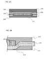
- Fig. 1 is a perspective view showing a state where part of a solar cell module according to Embodiment 1 is peeled
- Fig. 2A is a cross-sectional view thereof
- Fig. 2B is a cross-sectional view obtained by enlarging a portion surrounded by dotted lines of Fig. 2A .
- the solar cell module according to Embodiment 1 includes a solar cell device 103, an upper sealing portion 102 positioned over the solar cell device 103, a porous body 104 positioned below the solar cell device 103, a lower sealing portion 101 positioned below the porous body 104, an uppermost protective member 105 positioned over the upper sealing portion 102 and a back sheet 106 positioned below the lower sealing portion 101.
- the solar cell device 103 is sandwiched between the upper sealing portion 102 and the lower sealing portion 101.
- a dotted line of Fig. 2B denotes an interface 115 between the upper sealing portion 102 and the lower sealing portion 101.
- Vacuum lamination is performed in a state where the solar cell device 103 is sandwiched by the sheet-shaped upper sealing portion 102, the sheet-shaped porous body 104 and the sheet-shaped lower sealing portion 101, and the sheet-shaped uppermost protective member 105 and the sheet-shaped back sheet 106 are laminated above and below the solar cell device 103, thereby forming the solar cell module.
- the upper sealing portion 102 used in Embodiment 1 a high-polymer material having a total light transmittance of at least 50% or more is used.
- the transmittance is lower than 50%, a ratio in which light reaches the solar cell device 103 is low, which is not suitable to be used. Therefore, the upper sealing portion 102 preferably use a material with a transparency as high as possible.
- the lower sealing portion 101 is positioned below the solar cell device 103, and a high total light transmittance is not necessary.
- the lower sealing portion 101 uses a high-polymer material having better bonding property with respect to the upper sealing portion 102.
- the high-polymer material commonly used as the sealing material a material mainly containing an ethylene-vinyl acetate copolymer (EVA) is used.
- EVA ethylene-vinyl acetate copolymer
- a material obtained by adding an ultraviolet-light reflection filler such as titanium oxide into the material mainly containing ethylene-vinyl acetate copolymer (EVA) to thereby allow solar light to be easily reflected is used.
- resin components for the sealing portions an ethylene-unsaturated carboxylic acid copolymer or an ionomer thereof, a silicone resin, polyvinyl-butyral, a thermoplastic polyurethane resin, a polyolefin resin and so on can be cited, and it is also preferable to use the above materials for the lower sealing portion 101 and the upper sealing portion 102 by combining these materials for utilizing characteristics of materials.
- a material obtained by adding an antioxidant, a photostabilizer, an ultraviolet absorber, a coloring agent, a light diffusion agent, a flame retardant, an antitarnish agent, a silane coupling agent and so on can be additionally used for the lower sealing portion 101 for improving durability.
- the porous body 104 is preferably a porous sheet, and it is particularly preferable to use an organic nonwoven fabric.
- an organic nonwoven fabric a long-fiber nonwoven fabric as well as a short-fiber nonwoven fabric made of polyethylene terephthalate fibers, polyolefin fibers, or a fabric formed by entangling these two or more kinds of fibers can be used.
- a spunbonded-nonwoven fabric, a wetted-nonwoven fabric, a needle nonwoven fabric and the like can be used.
- the fiber material in which the difference of SP values between the sealing materials and the organic fibers is 1.0 or less, because affinity between the sealing materials with respect to the organic nonwoven fabric is increased, and the fluidity of the sealing materials can be suppressed in the laminating process or when used at a high temperature.
- a solution parameter is a value defined by a regular solution model introduced by Hildebrand, which is the value giving an indication of solubility of a binary solution.
- the value is also called a solubility parameter, a solution property parameter and a Hildebrand parameter.
- the solution parameter is used as a gauge indicating the intermolecular force.
- an actual solution is not always the regular solution, but it is empirically known that the solubility is increased as the difference of SP values between two components is reduced.
- the porous body 104 is preferably the porous sheet, not limited to the nonwoven fabric, and further preferably has the SP value in a range described above.
- the sheet formed by weaving various kinds of fibers is preferably used.
- the porous body 104 is not limited to the nonwoven fabric, and a fabric formed by weaving fibers regularly such as a plain weave, a twill weave, a satin weave, leno, nock leno, an oblique weave and a double weave is preferably used.
- a shape of the porous body 104 is not particularly limited, but a fiber diameter thereof is preferably 10 ⁇ m or more to 100 ⁇ m or less and a fiber apparent density is preferably 0.05g/cm 3 or more to 0.3g/cm 3 or less in consideration of infiltration property of the sealing material with respect to the inside of the porous body 104. The reason thereof will be explained in the following example.
- the sealing material of the upper sealing portion 102 and the sealing material of the lower sealing portion 101 respectively enter the porous body 104 to the interface 115 shown by the dotted line of Fig. 2B .
- the porous body 104 is preferably arranged so that an outer periphery thereof reaches an outer surface of the solar cell module. That is because the sealing material of the upper sealing portion 102 and the sealing material of the lower sealing portion 101 preferably do not directly contact each other.
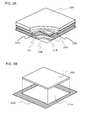
- Embodiment 2 a portion in which the solar cell device 103 is inserted is provided as an opening in the porous body 104.
- the opening will be explained with reference to Fig. 3A, Fig. 3B , Fig. 4A and Fig. 4B . Components not to be explained are the same as those of Embodiment 1.
- Fig. 3A is a perspective view obtained by breaking a corner portion of the solar cell module.
- Fig. 3B is an exploded view for explaining the relation between the solar cell device 103 and the porous body 104.
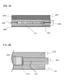
- Fig. 4A is a cross-sectional view of the solar cell module and Fig. 4B is an enlarged cross-sectional view of a portion surrounded by dotted lines of Fig. 4A .
- a dotted line in Fig. 4B is an interface 115 between the sealing material of the upper sealing portion 102 and the sealing material of the lower sealing portion 101.
- a sealing resin enters the porous body 104.
- An opening 114 is provided in the porous body 104 as shown in Fig. 3B , and the size of the opening 114 is larger than the size of the solar cell device 103 in a surface direction. Part of the sealing material of the upper sealing portion 102 and part of the sealing material of the lower sealing portion 101 contact at one portion through the opening 114 and bond to each other when they are laminated.
- the portion is a peripheral portion of the solar cell device 103.
- the portion is kept to the minimum as small as possible, because it is preferable that the sealing material of the upper sealing portion 102 and the sealing material of the lower sealing portion 101 do not directly contact each other. When they directly contact each other, the resin does not easily enter the porous body 104.
- the porous body 104, the upper sealing portion 102 and the lower sealing portion 101 preferably have a sheet shape in the same manner as in the case of the structures Fig. 1 , Figs. 2A and 2B . It is also preferable that the porous body 104 has a larger area than the upper sealing portion 102 and the lower sealing portion 101, and that the upper sealing portion 102 and the lower sealing portion 101 are not directly bonded in an outer peripheral side surface of the solar cell module. The reason thereof is that the resin does not easily enter the porous body 104 and that the entire strength is not increased when the porous body 104 is not used as described above.
- the solar cell is modularized by using a heat lamination method in which the sealing material of the upper sealing portion 102 and the sealing material of the lower sealing portion 101 are bonded by thermocompression in a temperature range in which the sealing materials can be softened and flow.
- the lamination is preferably performed in vacuum.
- a lamination method in the atmosphere is not suitable as a void is easily involved inside the porous body 104.
- the lower sealing portion 101 and the porous body 104 are previously bonded to perform sealing of the solar cell device 103 before the lamination of the solar cell module.
- the lower sealing portion 101 is pushed from one side and coated by using the porous body 104 as a base material, thereby forming a sealing material sheet having the porous body on one side.
- the above structure it is preferable to use the above structure as the positional displacement in the laminating process of the porous body 104 or variation in tensile force can be solved.
- solar cell device 103 various types of solar cell devices can be used, for example, ones made of silicon-based materials such as single-crystal silicon, polycrystal silicon and amorphous silicon, III-V or II-VI compound semiconductors such as gallium-arsenic, copper-indium-selenium and cadmium-tellurium.
- silicon-based materials such as single-crystal silicon, polycrystal silicon and amorphous silicon
- III-V or II-VI compound semiconductors such as gallium-arsenic, copper-indium-selenium and cadmium-tellurium.
- the sealing materials used in Embodiments 1 and 2 can be applied for sealing all types of the solar cell devices cited above.
- the uppermost protective member 105 a glass plate, an acrylic resin, a polycarbonate resin, a polyester resin, a fluorine-containing resin and so on can be used.
- a single layer or multilayer sheet such as various types of thermoplastic resin films can be used.
- multilayer sheets including, for example, metal such as tin, aluminum and stainless steel, polyester in which an inorganic material such as glass is laminated, inorganic-vapor deposition polyester, the fluorine-containing resin and polyolefin can be used.
- evaluation is performed based on a residual ratio of a light collection area of the solar cell device 103 by measuring the area as a visual inspection. Also, measurement using an ultrasonic depth measurement device (SAT) is performed. The evaluation is further performed by the number of generated voids. The evaluation is specifically performed as follows.
- the evaluation was performed by the total points (six is the best) of the above four evaluations.
- the evaluation is passed by two or more points in (1) and (2), and the evaluation is passed by one or more points in (3) and (4). When all items are satisfied, the module is passed as a product. Conditions and results are shown in Table 1.
- the sealing material of the upper sealing portion 102 the ethylene-vinyl acetate copolymer (EVA) sheet with a total light transmittance of 92% (measured by Haze Meter-HR-100 manufactured by MURAKAMI COLOR RESEARCH LABORATORY) was used.
- a sealing material obtained by allowing the ethylene-vinyl acetate copolymer to contain 5wt% rutile-type titanium dioxide with a total light reflectance of 75% was used.
- the EVA sheet with the total light transmittance of 92% as the sealing material of the upper sealing portion 102 was put on a white-plate tempered glass as the uppermost protective member 5, and the solar cell device 103 was put thereon.
- the polyester spunbond as the organic nonwoven fabric was overlaid as the porous body 104, then, the white EVA sheet containing titanium dioxide as the sealing material of the lower sealing portion 101 was put, and a polyester film having a thickness of 0.1mm was arranged as the back sheet 106.
- the solar cell module was made by using the vacuum lamination molding (molding temperature 150°C, load 1000kg.m2).
- the white lower sealing portion 101 was arranged on a back surface of the solar cell device 103 and the lamination could be performed so as not to cover the solar light irradiation surface of the solar cell device 103. Even after the heat cycle test was performed 200 cycles, movement due to the flowage of the sealing material of the lower sealing portion 101 to the solar light irradiation surface of the solar cell device 103 was not recognized.
- the porous body 104 was shaped so as to have an opening of the same area as the area of the solar cell device 103 in a part where the solar cell device 103 was arranged as shown in Fig. 3A and Fig. 3B and laminated so that the solar cell device 103 was fitted thereto.
- the solar cell module was made in the same manner as Example 1 except for that point.
- the irradiation area could be secured as the white material of the sealing material for the lower sealing portion 101 did not cover the solar light irradiation surface and generation of voids was not recognized.
- the fibers in which the difference of SP values with respect to respective sealing materials is 1.0 or less were entangled, infiltration and adhesion between two kinds of sealing materials and the porous body 104 was good and the flowage of the sealing materials did not occur even in the 200 cycles heat cycle reliability test.
- the solar cell module was made in the same manner as Example 1 except for a point that a polyester spunbond having a different fabric diameter was used as the organic nonwoven fabric for the porous body 104.
- the solar cell module obtained after the lamination molding was molded so that the white sealing material of the lower sealing portion 101 did not protrude to the solar light irradiation surface of the solar cell device 103, and so that a residual ratio was 100% with respect to the surface area of the solar cell device 103 before modularization without voids and flowage after the heat cycle test, that is, the condition was good.
- a polyester spunbond having a different fabric diameter was used as the organic nonwoven fabric for the porous body 104.
- the solar cell module was made in the same manner as Example 1 except for that point.
- the solar cell module obtained after the lamination molding was molded so that the white sealing material of the lower sealing portion 101 did not protrude to the solar light irradiation surface of the solar cell device 103, and so that the residual ratio was 100% with respect to the surface area of the solar cell device 103 before modularization without voids and flowage after the heat cycle test, that is, the condition was good.
- a polyester spunbond having a different apparent density was used as the organic nonwoven fabric for the porous body 104.
- the solar cell module was made in the same manner as Example 1 except for that point.
- the solar cell module after the lamination molding was molded so that the white lower sealing portion 101 did not protrude to the solar light irradiation surface of the solar cell device 103, and so that the residual ratio was 100% with respect to the surface area of the solar cell device 103 before modularization without voids and flowage after the heat cycle test, that is, the condition was good.
- a polyester spunbond having a different apparent density was used as the organic nonwoven fabric for the porous body 104.
- the solar cell module was made in the same manner as Example 1 except for that point.
- the solar cell module after the lamination molding was molded so that the white sealing material of the lower sealing portion 101 did not protrude to the solar light irradiation surface of the solar cell device 103, and so that the residual ratio was 100% with respect to the surface area of the solar cell device 103 before modularization without voids and flowage after the heat cycle test, that is, the condition was good.
- the solar cell module was obtained by vacuum lamination molding using the two sealing materials used in Example 1 without the lamination of the organic nonwoven fabric as the porous body 104. Conditions were the same as Example 1 except for that point.
- the solar cell module after the lamination molding was molded so that the white sealing material of the lower sealing portion 101 protruded to the solar light irradiation surface of the solar cell device 103, and the light collection area was 7% reduced with respect to the surface area of the solar cell device 103 before modularization. Accordingly, the power generation efficiency was deteriorated.
- a meltblown nonwoven fabric with polyester extremely thin fibers was used as the organic nonwoven fabric for the porous body 104, and the EVA resin was used for the sealing material of the lower sealing portion 101 and the sealing material of the upper sealing portion 102 to thereby obtain the solar cell module by the vacuum lamination molding.
- Conditions were the same as Example 1 except for that point.
- the solar cell module after the lamination molding was molded so that the white sealing material of the lower sealing portion 101 did not protrude to the solar light irradiation surface of the solar cell device 103, however, voids were found in the central part when checking voids by SAT. Furthermore, voids were grown as compared with the state before the heat cycle test when checking voids again after performing the heat cycle test in that state.
- a polyester needle nonwoven fabric with a different fiber diameter was used as the organic nonwoven fabric for the porous body 104.
- the solar cell module was obtained in the same manner as Example 1 except for that point.
- the obtained solar cell module was molded so that the white resin of the lower sealing portion 101 covered the solar light irradiation surface of the solar cell device 103, therefore, the irradiation area was reduced.
- a polyester spunbonded nonwoven fabric with a different apparent density was used as the organic nonwoven fabric for the porous body 104.
- the solar cell module was obtained in the same manner as Example 1 except for that point.
- the sealing material of the lower sealing portion 101 and the sealing material of the upper sealing portion 102 tend to flow into the organic nonwoven fabric for the porous body 104, and the solar cell module was molded so that the white resin as the sealing material for the lower sealing portion 101 covered the solar light irradiation surface of the solar cell device 103 in the lamination process, therefore, the irradiation area was reduced.
- the solar cell module was obtained in the same manner as Example 1 except that a polyester spunbonded nonwoven fabric with a different apparent density was used as the organic nonwoven fabric. Conditions were the same as Example 1 except for that point.
- the obtained solar cell module was molded so that the white resin as the sealing materials for the lower sealing portion 101 did not cover the solar light irradiation surface of the solar cell device 103, voids were generated at an interface between the upper sealing portion 102 and the lower sealing portion 101 when performing the heat cycle reliability test.
- the porous body 104 is formed by using PET type fibers with the SP values of 10.7 and 8.0 by being mixed and entangled, which have higher affinity respectively with respect to the sealing material for the upper sealing portion 102 with the SP value of 11.5 and the sealing material for the lower sealing portion 101 with the SP value of 8.0, therefore, the affinity between the porous body 104 and the sealing materials is increased and the infiltration property is increased to thereby reduce the generation of voids, which suppresses flowability of the sealing materials at the high temperature.
- the difference of SP values between the sealing materials for the lower sealing portion 101 as well as the sealing material for the upper sealing portion 102 and the organic nonwoven fabric for the porous body 104 is 0.8 or less.
- the following both differences are required to be 0.8 or less, that is, the difference between the SP value of a fiber having a higher SP value in the organic nonwoven fabric as the porous body 104 and the SP value of a sealing material having a higher SP value in the lower sealing portion 101 and the upper sealing portion 102, that is, the difference between the SP value of a fiber having a lower SP value in the organic nonwoven fabric as the porous body 104 and the SP value of a sealing material having a lower SP value in the lower sealing portion 101 and the upper sealing portion 102.
- the firm solar cell module having good adhesion between respective fibers and the sealing resins can be obtained.
- the above can be applied by the comparison using the highest SP value and the smallest SP value.
- the difference of SP values between the sealing material for the lower sealing portion 101 and the sealing material for the upper sealing portion 102 is at least lower than 3.5, and is preferably 1.0 or less which is approximately equal to 0.8 from the results as the plural fibers described above according to the comparisons in Comparative Example 2 and Example 3.
- Example 4 when the fiber diameter of the organic nonwoven fabric for the porous body 104 is lower than 10 ⁇ m, the nonwoven fabric tends to be dense as fibers forming the fabric are thin, as a result, the sealing materials are not easily infiltrated into the porous material 104 from both sides at the time of the vacuum lamination in the process of modularization.
- the apparent density also differs in addition to the fiber diameter in Example 4 and Comparative Example 3.
- the apparent density is preferably 0.05 to 0.30g/cm 3 as described below, and the apparent densities in Example 4 and Comparative Example 3 are within this range as well as the difference is small and does not affect the result.
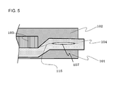
- Fig. 5 is a view corresponding to Fig. 2A , showing a cross-sectional view of a solar cell module in which a void 107 is involved inside the organic nonwoven fabric as the porous body 104.
- a void 107 is involved inside the organic nonwoven fabric as the porous body 104.
- Such failure tends to occur when the fiber diameter is smaller than 10 ⁇ m.
- the fiber diameter is larger than 100 ⁇ m, it is not preferable because the void between fibers becomes too large and the sealing material can be easily passed therethrough, which causes the flowage of the sealing material through the nonwoven fabric as can be seen from Example 5 and Comparative Example 4. Accordingly, it is necessary that the fabric diameter is 10 ⁇ m or more to 100 ⁇ m or less.
- Example 6 and Comparative Example 5 when the fiber apparent density is lower than 0.05g/cm 3 , the organic nonwoven fabric as the porous body 104 becomes a fabric with a small amount of fibers and a large number of voids, therefore, it is not preferable because the sealing material is easily passed through the organic nonwoven fabric and the flowage of the sealing material occurs at the time of heating in the laminating process or in use.
- the fabric apparent density requires to be 0.05g/cm 3 or more.
- the fiber apparent density is higher than 0.30g/cm 3
- the organic nonwoven fabric as the porous body 104 tends to be dense as can be seen from Example 7 and Comparative Example 6, and it is not suitable because the infiltration of the sealing members into the porous body 104 becomes worse and the void 107 tends to occur inside the porous body 104 as shown in Fig. 5 .
- the fiber apparent density requires to be 0.30g/cm 3 or less.
- the fiber apparent density is required to be 0.05g/cm 3 or more to 0.30g/cm 3 or less.
- the opening 114 is provided in the organic nonwoven fabric as the porous body 104 only in Embodiment 2, however, the relation in the example can be similarly applied to examples not having the opening 114.
- the organic nonwoven fabric has been mainly explained as the porous body 104, however, sheet type porous bodies such as a woven fabric of fibers and a resin sheet provided with many openings may be applied in addition to the nonwoven fabric.
- the woven fabric of fibers has uniform and three-dimensional openings, which is suitable as the resin can easily enter the fabric.
- the nonwoven fabric is further suitable as it has irregular fibers and various openings, therefore, the resin can easily enter the fabric.
- Embodiments 1 and 2 can be combined as long as there is no hindrance.
- the present invention can be used for the solar cell module.
Landscapes
- Photovoltaic Devices (AREA)
Applications Claiming Priority (2)
| Application Number | Priority Date | Filing Date | Title |
|---|---|---|---|
| JP2012140483 | 2012-06-22 | ||
| PCT/JP2013/003776 WO2013190823A1 (fr) | 2012-06-22 | 2013-06-18 | Module de cellule solaire |
Publications (2)
| Publication Number | Publication Date |
|---|---|
| EP2866266A1 true EP2866266A1 (fr) | 2015-04-29 |
| EP2866266A4 EP2866266A4 (fr) | 2015-10-21 |
Family
ID=49768437
Family Applications (1)
| Application Number | Title | Priority Date | Filing Date |
|---|---|---|---|
| EP13807231.9A Withdrawn EP2866266A4 (fr) | 2012-06-22 | 2013-06-18 | Module de cellule solaire |
Country Status (5)
| Country | Link |
|---|---|
| US (1) | US20150187977A1 (fr) |
| EP (1) | EP2866266A4 (fr) |
| JP (1) | JP6089214B2 (fr) |
| CN (1) | CN104380482B (fr) |
| WO (1) | WO2013190823A1 (fr) |
Families Citing this family (2)
| Publication number | Priority date | Publication date | Assignee | Title |
|---|---|---|---|---|
| JP6541106B2 (ja) * | 2015-07-02 | 2019-07-10 | パナソニックIpマネジメント株式会社 | 太陽電池モジュール |
| KR102932635B1 (ko) * | 2020-02-27 | 2026-03-03 | 주식회사 쿠라레 | 토목용 방수 시트 |
Family Cites Families (11)
| Publication number | Priority date | Publication date | Assignee | Title |
|---|---|---|---|---|
| JPS6112694Y2 (fr) * | 1980-05-23 | 1986-04-19 | ||
| JPS601875A (ja) * | 1983-06-20 | 1985-01-08 | Toshiba Corp | 太陽電池パネル |
| JP2651121B2 (ja) * | 1993-05-18 | 1997-09-10 | キヤノン株式会社 | 太陽電池モジュール及びその設置方法 |
| JP3687701B2 (ja) * | 1995-05-08 | 2005-08-24 | 株式会社ブリヂストン | 太陽電池モジュール |
| JP2915327B2 (ja) * | 1995-07-19 | 1999-07-05 | キヤノン株式会社 | 太陽電池モジュール及びその製造方法 |
| JP3825843B2 (ja) * | 1996-09-12 | 2006-09-27 | キヤノン株式会社 | 太陽電池モジュール |
| JP5004884B2 (ja) * | 2008-07-07 | 2012-08-22 | 三菱電機株式会社 | メンブレンリフレクタおよびその製造方法 |
| WO2010051355A2 (fr) * | 2008-10-31 | 2010-05-06 | Dow Corning Corporation | Module de piles photovoltaïques et procédé de formation |
| US20100224235A1 (en) * | 2009-03-06 | 2010-09-09 | E.I. Du Pont De Nemours And Company | Light weight solar cell modules |
| JP2011249720A (ja) * | 2010-05-31 | 2011-12-08 | Kst Co Ltd | パネルの接着用シート、パネルの製造方法、パネルの封止用シート、太陽電池の封止用シート、太陽電池の製造方法 |
| JP2012004146A (ja) | 2010-06-14 | 2012-01-05 | Bridgestone Corp | 太陽電池用封止膜及びこれを用いた太陽電池 |
-
2013
- 2013-06-18 CN CN201380033137.0A patent/CN104380482B/zh not_active Expired - Fee Related
- 2013-06-18 EP EP13807231.9A patent/EP2866266A4/fr not_active Withdrawn
- 2013-06-18 JP JP2014520950A patent/JP6089214B2/ja not_active Expired - Fee Related
- 2013-06-18 US US14/404,623 patent/US20150187977A1/en not_active Abandoned
- 2013-06-18 WO PCT/JP2013/003776 patent/WO2013190823A1/fr not_active Ceased
Also Published As
| Publication number | Publication date |
|---|---|
| CN104380482B (zh) | 2017-04-12 |
| EP2866266A4 (fr) | 2015-10-21 |
| CN104380482A (zh) | 2015-02-25 |
| JPWO2013190823A1 (ja) | 2016-02-08 |
| JP6089214B2 (ja) | 2017-03-08 |
| US20150187977A1 (en) | 2015-07-02 |
| WO2013190823A1 (fr) | 2013-12-27 |
Similar Documents
| Publication | Publication Date | Title |
|---|---|---|
| JP5365140B2 (ja) | 太陽電池バックシート | |
| CN101933164B (zh) | 光电组件及制造方法 | |
| JP6767708B2 (ja) | 太陽電池モジュール | |
| CN102884639A (zh) | 辐射收集装置 | |
| TWI605606B (zh) | Solar battery module | |
| US20240286391A1 (en) | Resin film for current collector sheet, current collector sheet, solar cell element with current collector sheet, and solar cell | |
| WO2013145116A1 (fr) | Film d'étanchéité de module de cellule solaire et module de cellule solaire l'utilisant | |
| JPWO2013069680A1 (ja) | 太陽電池モジュール | |
| Kim et al. | Recent developments of polymer-based encapsulants and backsheets for stable and high-performance silicon photovoltaic modules: Materials nanoarchitectonics and mechanisms | |
| JP6288902B2 (ja) | 反射性を有する太陽電池用裏面保護シート | |
| Babin et al. | Water vapor permeability of polymeric packaging materials for novel glass‐free photovoltaic applications | |
| EP2866266A1 (fr) | Module de cellule solaire | |
| JP2013191673A (ja) | フレキシブル太陽電池モジュール | |
| KR102253838B1 (ko) | 태양 전지 모듈 및 이에 사용되는 후면 시트 | |
| TWI474492B (zh) | 增強光捕捉之太陽光電模組 | |
| JP2019062088A (ja) | 太陽電池モジュール | |
| WO2015190046A1 (fr) | Module de cellule solaire | |
| JP5484762B2 (ja) | 太陽電池モジュール用保護シートの製造方法 | |
| JP2014179513A (ja) | 太陽電池モジュール及びその製造方法 | |
| JP2014036044A (ja) | 太陽電池モジュール | |
| Masuda et al. | Tolerance to hygrothermal and high-voltage stresses for Si-related photovoltaic modules with newly-developed polyvinyl butyral encapsulants | |
| US20130153005A1 (en) | Reinforcement element for thin film photovoltaic devices and their methods of manufacture | |
| JP6471501B2 (ja) | 太陽電池モジュール用裏面保護シート及びこれを用いた太陽電池モジュール | |
| JPWO2018150893A1 (ja) | 太陽電池モジュール | |
| TWI419342B (zh) | 太陽光電模組封裝疊層結構及其製造方法 |
Legal Events
| Date | Code | Title | Description |
|---|---|---|---|
| PUAI | Public reference made under article 153(3) epc to a published international application that has entered the european phase |
Free format text: ORIGINAL CODE: 0009012 |
|
| 17P | Request for examination filed |
Effective date: 20141113 |
|
| AK | Designated contracting states |
Kind code of ref document: A1 Designated state(s): AL AT BE BG CH CY CZ DE DK EE ES FI FR GB GR HR HU IE IS IT LI LT LU LV MC MK MT NL NO PL PT RO RS SE SI SK SM TR |
|
| AX | Request for extension of the european patent |
Extension state: BA ME |
|
| DAX | Request for extension of the european patent (deleted) | ||
| RA4 | Supplementary search report drawn up and despatched (corrected) |
Effective date: 20150917 |
|
| RIC1 | Information provided on ipc code assigned before grant |
Ipc: H01L 31/048 20140101AFI20150911BHEP |
|
| 17Q | First examination report despatched |
Effective date: 20171016 |
|
| GRAP | Despatch of communication of intention to grant a patent |
Free format text: ORIGINAL CODE: EPIDOSNIGR1 |
|
| INTG | Intention to grant announced |
Effective date: 20190128 |
|
| STAA | Information on the status of an ep patent application or granted ep patent |
Free format text: STATUS: THE APPLICATION IS DEEMED TO BE WITHDRAWN |
|
| 18D | Application deemed to be withdrawn |
Effective date: 20190608 |