EP2866423B1 - Kommunikationsvorrichtung, verfahren zur steuerung einer kommunikationsvorrichtung und programm - Google Patents
Kommunikationsvorrichtung, verfahren zur steuerung einer kommunikationsvorrichtung und programm Download PDFInfo
- Publication number
- EP2866423B1 EP2866423B1 EP13806406.8A EP13806406A EP2866423B1 EP 2866423 B1 EP2866423 B1 EP 2866423B1 EP 13806406 A EP13806406 A EP 13806406A EP 2866423 B1 EP2866423 B1 EP 2866423B1
- Authority
- EP
- European Patent Office
- Prior art keywords
- unit
- display
- input
- call
- voice call
- Prior art date
- Legal status (The legal status is an assumption and is not a legal conclusion. Google has not performed a legal analysis and makes no representation as to the accuracy of the status listed.)
- Active
Links
Images


Classifications
-
- H—ELECTRICITY
- H04—ELECTRIC COMMUNICATION TECHNIQUE
- H04M—TELEPHONIC COMMUNICATION
- H04M1/00—Substation equipment, e.g. for use by subscribers
- H04M1/72—Mobile telephones; Cordless telephones, i.e. devices for establishing wireless links to base stations without route selection
- H04M1/724—User interfaces specially adapted for cordless or mobile telephones
- H04M1/72403—User interfaces specially adapted for cordless or mobile telephones with means for local support of applications that increase the functionality
- H04M1/72445—User interfaces specially adapted for cordless or mobile telephones with means for local support of applications that increase the functionality for supporting Internet browser applications
-
- H—ELECTRICITY
- H04—ELECTRIC COMMUNICATION TECHNIQUE
- H04M—TELEPHONIC COMMUNICATION
- H04M1/00—Substation equipment, e.g. for use by subscribers
- H04M1/02—Constructional features of telephone sets
- H04M1/0202—Portable telephone sets, e.g. cordless phones, mobile phones or bar type handsets
- H04M1/0254—Portable telephone sets, e.g. cordless phones, mobile phones or bar type handsets comprising one or a plurality of mechanically detachable modules
- H04M1/0256—Portable telephone sets, e.g. cordless phones, mobile phones or bar type handsets comprising one or a plurality of mechanically detachable modules wherein the modules are operable in the detached state, e.g. one module for the user interface and one module for the transceiver
-
- H—ELECTRICITY
- H04—ELECTRIC COMMUNICATION TECHNIQUE
- H04M—TELEPHONIC COMMUNICATION
- H04M1/00—Substation equipment, e.g. for use by subscribers
- H04M1/72—Mobile telephones; Cordless telephones, i.e. devices for establishing wireless links to base stations without route selection
- H04M1/724—User interfaces specially adapted for cordless or mobile telephones
-
- H—ELECTRICITY
- H04—ELECTRIC COMMUNICATION TECHNIQUE
- H04M—TELEPHONIC COMMUNICATION
- H04M1/00—Substation equipment, e.g. for use by subscribers
- H04M1/72—Mobile telephones; Cordless telephones, i.e. devices for establishing wireless links to base stations without route selection
- H04M1/724—User interfaces specially adapted for cordless or mobile telephones
- H04M1/72448—User interfaces specially adapted for cordless or mobile telephones with means for adapting the functionality of the device according to specific conditions
-
- H—ELECTRICITY
- H04—ELECTRIC COMMUNICATION TECHNIQUE
- H04M—TELEPHONIC COMMUNICATION
- H04M3/00—Automatic or semi-automatic exchanges
- H04M3/02—Calling substations, e.g. by ringing
-
- H—ELECTRICITY
- H04—ELECTRIC COMMUNICATION TECHNIQUE
- H04M—TELEPHONIC COMMUNICATION
- H04M2250/00—Details of telephonic subscriber devices
- H04M2250/16—Details of telephonic subscriber devices including more than one display unit
Definitions
- the present invention relates to a separate-type communication device, a control method of the communication device, and a program.
- Configurations include, for example, the so-called straight-type configuration that is composed of one case (unit) in which a display unit and an input unit for receiving operation input are provided on the same surface, and the so-called folding-type configuration in which a first unit provided with a display unit and a second unit provided with an input unit are joined by way of a hinge so as to allow opening and closing.
- Patent Document 1 ( WO 2006/051669 A1 ) discloses a sliding-type communication device in which a first unit provided with a first display unit and a second unit provided with a second display unit are joined so as to allow sliding.
- Non-Patent Document 1 discloses the so-called separate-type communication device that is equipped with a first unit provided with a display unit and a second unit that is detachably attached to the first unit and that is provided with a transceiver unit for carrying out voice call.
- a user When a user carries out voice call by use of a communication device, the user holds the communication device in a state with the speaker in the communication device is in proximity to the user's ear. In this state, the user is unable to view the display of the display unit in the above-described straight, folding, or sliding types of communication devices.
- the ease of use of the device is compromised because, even though the Web page is being displayed on the display unit, the user is unable to carry out voice call while looking at the display unless the user uses, for example, a headset.
- Non-Patent Document 1 at the time of voice call, the user separates the first unit and second unit and then holds the second unit for carrying out voice call and holds the first unit such that the display of the display unit can be easily seen, whereby the display of the display unit can be easily viewed and the ease of use during voice call is improved.
- Patent Document 1 WO 2006/051669 A1
- Non-Patent Document 1 "F-04B User's Manual" (June 1, 2012 search) Internet ⁇ http://www.nttdocomo.co.jp/support/trouble/manual/download/fo4b/index.html>
- US2010/0143769 relates to a dual display mobile communication device comprising a first display and a second display wherein the mobile device can operate as a mobile cell phone.In a closed configuration of the mobile device, the first display is exposed and the second display is hidden. In an open configuration, both displays are exposed.
- US2010/0227642 relates to a mobile terminal including sub-device that is attached to or detached from the terminal, to remotely control operation and state of the terminal.
- Non-Patent Document 1 has the problem that, being equipped with only one display unit, it becomes difficult to view the display when a large amount of information is to be viewed at one time. Because a communication device such as a mobile telephone or smartphone is normally carried by the user and the device size is limited, the size of the display unit is therefore limited. As a result, it is difficult to remedy this problem by increasing the size of the display unit.
- An object of the present invention is to provide a communication device, a control method of the communication device, and a program that facilitate viewing the display of a display unit and thus improve the ease of use during voice call.
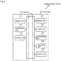
- FIG. 1 is a block diagram showing the essential configuration of communication device 100 of the first exemplary embodiment of the present invention.
- the communication device according to the present invention is equipped with communication functions for carrying out, for example, an outgoing call function and incoming call function, transmission and reception of email, and access to the Internet.
- Specific examples of communication device 100 include a mobile telephone, a smartphone, a tablet or notebook personal computer, a portable game device, and a PDA (Personal Digital Assistant).
- Communication device 100 is the so-called separate-type communication device that is equipped with call unit 110, and view unit 130 that is detachably attached to call unit 110.
- Call unit 110 is an example of the first unit
- view unit 130 is an example of the second unit.
- Call unit 110 includes display unit 111, transmitter unit 112, and receiver unit 113.
- View unit 130 includes display unit 131, input unit 132, communication unit 133, detection unit 134, and control unit 135.
- Display unit 111 is an example of the first display unit
- display unit 131 is an example of the second display unit.
- call unit 110 and view unit 130 are linked, the components in call unit 110 and in view unit 130 are each connected together by way of bus 150.
- call unit 110 and view unit 130 are separated, each of the components in call unit 110 are connected together by way of bus 150, and each of the components in view unit 130 are connected together by way of bus 150.
- call unit 110 and view unit 130 are capable of short-range wireless communication when in the separated state. In FIG. 1 , description of the configuration for carrying out short-range wireless communication has been omitted.
- Display unit 111 is, for example, an LCD (Liquid Crystal Display) and displays images under the control of control unit 135.
- LCD Liquid Crystal Display
- Transmitter unit 112 is, for example, a microphone and outputs a voice signal of an input voice.
- Receiver unit 113 is, for example, a speaker and reproduces an input voice signal.
- Display unit 131 is, for example, an LCD and displays images under the control of control unit 135.
- Input unit 132 accepts operation input from the user.
- Specific examples of input unit 132 include key buttons or a touch pad that detects contact with or proximity of, for example, a finger or a stylus pen.
- the touch panel is constructed by being overlaid on display unit 131.
- Input unit 132 may also be provided on call unit 110, and may be provided on both call unit 110 and view unit 130.
- Communication unit 133 can communicate by way of a network, and upon receiving input indicating that voice call is to be carried out, transmits a voice signal that is output from transmitter unit 112 to the communication partner by way of the network, and inputs to receiver unit 113 the voice signal from the communication partner that is received by way of the network.
- the input and output of voice signals between communication unit 133 and transmitter unit 112 and receiver unit 113 are carried out by way of bus 150 when call unit 110 and view unit 130 are in the linked state and are carried out by way of short-range wireless communication when call unit 110 and view unit 130 are in the separated state.
- communication unit 133 carries out, for example, the transmission and reception of email and the transmission and reception of data necessary for browsing Web pages by way of a network in accordance with input by way of input unit 132.
- Communication unit 133 may also be provided in call unit 110.
- Detection unit 134 detects whether or not call unit 110 and view unit 130 are in the linked state and outputs the detection result. Detection unit 134 may also be provided in call unit 110.
- Control unit 135 executes an application in accordance with input by way of input unit 132, and when voice call is not being carried out, displays images that correspond to the execution of the application on display unit 111 and display unit 131.
- control unit 135 Upon receiving input by way of input unit 132 indicating that voice call is to be carried out, and moreover, when the detection result of detection unit 134 indicates that call unit 110 and view unit 130 are in the separated state, control unit 135 displays images that correspond to the execution of the application on display unit 131.
- Control unit 135 may also be provided in call unit 110, and may also be provided separately in call unit 110 and view unit 130.
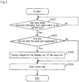
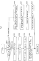
- FIG. 2 is a flow chart showing the display control operations during voice call.
- Control unit 135 is assumed to be executing an application and bringing about the display of images that correspond to the execution of the application on display unit 111 and display unit 131.
- Control unit 135 judges whether or not input has been received indicating that voice call is to be carried out (indicating that an outgoing call is to be carried out, or indicating that a response is to be made to an incoming call) (Step S201).
- Step S201 If input is not received indicating that voice call is to be carried out (Step S201: No), control unit 135 repeats the process of Step S201.
- control unit 135 judges whether or not call unit 110 and view unit 130 are in the separated state based on the detection result of detection unit 134 (Step S202).
- control unit 135 brings about display of images that correspond to the execution of the application on display unit 131 of view unit 130 (Step S203).
- control unit 135 starts the voice call on communication unit 133 (Step S204).
- Step S202 determines whether call unit 110 and view unit 130 are in the separated state. If call unit 110 and view unit 130 are not in the separated state (Step S202: No), control unit 135 proceeds to the process of Step S204. If call unit 110 and view unit 130 are not in the separated state, the display of one or both of display units 111 and 131 may be turned OFF.
- communication device 100 is equipped with call unit 110 that includes display unit 111 and view unit 130 that is detachably attached to call unit 110 and that includes display unit 131; and when not carrying out voice call, causes display of images that correspond to the execution of an application on display unit 111 and display unit 131, and upon receiving input indicating that voice call is to be carried out, and moreover, when call unit 110 and view unit 130 are in the separated state, causes display of images that correspond to the execution of the application on display unit 131.
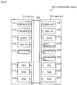
- FIG. 3 is a block diagram showing the essential configuration of communication device 200 of the second exemplary embodiment of the present invention.
- Communication device 200 is the so-called separate-type communication device that is equipped with call unit 210 and view unit 230 that is detachably attached to call unit 210.
- call unit 210 and view unit 230 are linked so as to allow opening and closing.
- Call unit 210 is one example of the first unit
- view unit 230 is one example of the second unit.
- Call unit 210 includes display unit 211, microphone 212, speaker 213, input unit 214, communication IC (Integrated Circuit) 215, CPU (Central Processing Unit) 216, RAM (Random Access Memory) 217, and ROM (Read Only Memory) 218.
- IC Integrated Circuit
- CPU Central Processing Unit
- RAM Random Access Memory
- ROM Read Only Memory
- View unit 230 includes display unit 231, input unit 232, sensor 233, state detection unit 234, communication IC 235, communication unit 236, CPU 237, RAM 238, and ROM 239.
- Display unit 211 is an example of the first display unit, and display unit 231 is an example of the second display unit.
- microphone 212 is an example of the transmitter unit, and the speaker is an example of the receiver unit.
- Sensor 233 and state detection unit 234 make up the detection unit.
- CPU 216, RAM 217, ROM 218, CPU 237, RAM 238, and ROM 239 make up the control unit.
- each of the components in call unit 210 and in view unit 230 are connected together by way of bus 250.
- each of the components in call unit 210 are connected together by way of bus 250, and each of the components in view unit 230 are connected together by way of bus 250.
- Display unit 211 is, for example, an LCD and displays images under the control of CPU 216 or CPU 237.
- Microphone 212 outputs a voice signal of an input voice.
- Speaker 213 reproduces an input voice signal.
- Input unit 214 corresponds to input unit 132 in the first exemplary embodiment, and accepts the operation input from the user.
- Communication IC 215 carries out short-range wireless communication such as Bluetooth (registered trademark) with view unit 230.
- CPU 216 executes an application in accordance with input by way of input unit 214 or input unit 232 and carries out display control of images that correspond to the execution of the application.
- RAM 217 temporarily stores, for example, data necessary for CPU 216 to carry out various processes.
- ROM 218 stores, for example, a control program for CPU 216 to carry out various processes.
- Display unit 231 is, for example, an LCD and displays images under the control of CPU 216 or CPU 237.
- Input unit 232 corresponds to input unit 132 of the first exemplary embodiment and accepts the operation input from the user.
- Sensor 233 monitors signals that change according to changes in the state of communication device 200.
- State detection unit 234 detects the state of communication device 200 (whether call unit 210 and view unit 230 are in the separated state or the linked state, and further, when call unit 210 and view unit 230 are in the linked state, the closed/opened state of call unit 210 and view unit 230) based on the result of monitoring of sensor 233.
- sensor 233 monitors, for example, the transmission and receipt of signals between call unit 210 and view unit 230 by way of bus 250.
- call unit 210 and view unit 230 are in the separated state, the transmission and receipt of signals between call unit 210 and view unit 230 by way of bus 250 are interrupted, and state detection unit 234 therefore detects whether call unit 210 and view unit 230 are in the separated state or linked state based on changes of these signals.
- a permanent magnet is disposed in either call unit 210 or view unit 230 and a Hall element is disposed in the other, and sensor 233 monitors the output voltage of the Hall element. Because the output voltage of a Hall element changes with changes in the opened/closed state of call unit 210 and view unit 230 due to the strength of the magnetic flux from the permanent magnet, state detection unit 234 detects the opened/closed state of call unit 210 and view unit 230 based on the change of the output voltage of this Hall element.
- Communication IC 235 carries out short-range wireless communication with call unit 210.
- Communication unit 236 is able to communicate by way of a network, and upon receiving input indicating that voice call is to be carried out, transmits a voice signal that is output from microphone 212 to the communication partner by way of the network, and further, inputs to speaker 213 the voice signal that is received from the communication partner by way of the network.
- the input and output of voice signals between communication unit 236 and microphone 212 and between communication unit 236 and speaker 213 are carried out by way of bus 250 when call unit 210 and view unit 230 are in the linked state and are carried out by way of short-range wireless communication when call unit 210 and view unit 230 are in the separated state.
- CPU 237 together with CPU 216 execute an application in accordance with input by way of input unit 214 or input unit 232 and carry out display control of images that correspond to the execution of the application.
- RAM 238 temporarily stores, for example, data necessary for CPU 237 to carry out various processes.
- ROM 239 stores, for example, a control program for CPU 237 to carry out various processes.
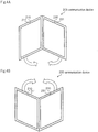
- FIGs. 4A and 4B show the external appearance of communication device 200.
- FIGs. 4A and 4B only display unit 211 and display unit 231 are shown, and the description of other configuration is omitted.
- Call unit 210 and view unit 230 are linked to allow opening and closing of substantially 360 degrees such that the inner sides of display unit 211 and display unit 231 face each other ( FIG. 4A ) or such that the outer sides of display unit 211 and display unit 231 face each other ( FIG. 4B ).
- the state in which communication device 200 is folded such that the outer sides of display unit 211 and display unit 231 face each other is referred to as the fully-opened state.
- Call unit 210 is provided with microphone 212 and speaker 213 on the same surface as display unit 211.
- Microphone 212 is arranged so as to be positioned in the vicinity of the user's mouth in a state in which the user holds call unit 210 to carry out voice call
- speaker 213 is arranged so as to be positioned in the vicinity of the user's ear in a state in which the user holds call unit 210 to carry out voice call.
- Communication device 200 is capable of voice call when call unit 210 and view unit 230 are in the separated state and in the fully-opened state.
- FIG. 5 is a flow chart showing the operation at the time of an incoming call of communication device 200.
- call unit 210 and view unit 230 are assumed to be in the linked state.
- input is assumed to have been received indicating the viewing of email and the viewing of a photograph, and, as shown in FIG. 6 , an image is displayed on display unit 211 of call unit 210 that corresponds to the execution of a photograph-viewing application and an image is displayed on display unit 231 of view unit 230 that corresponds to an email application.
- CPU 237 Upon incoming call, CPU 237 notifies CPU 216 by way of bus 250 of the incoming call (Step S501). Having received this notification, CPU 216 activates the call application (Step S502).
- CPU 237 activates communication IC 235
- CPU 216 activates communication IC 215 (Step S503).
- Communication IC 235 and communication IC 215 are thus able to perform short-range wireless communication.
- CPU 237 requests state detection unit 234 to detect the state of communication device 200, and based on the detection result of state detection unit 234, judges whether or not call unit 210 and view unit 230 are in the separated state, and further, whether or not call unit 210 and view unit 230 are in the fully-opened state (Step S504).
- CPU 237 repeats the process of Step 504.
- CPU 237 When call unit 210 and view unit 230 are in the separated state, CPU 237, having received input indicating that voice call is to be carried out, notifies call unit 210 by way of communication IC 235 that voice call is to be started in a state in which call unit 210 and view unit 230 are in the separated state by way of communication IC 235.
- CPU 216 having received this notification, causes microphone 212 and speaker 213 to begin processing.
- CPU 237 causes communication unit 236 to begin transmitting and receiving voice signals by way of the network and to begin the input and output of voice signals with microphone 212 and speaker 213, thereby entering a call-enabled state (Step S505).
- CPU 216 turns OFF the display of display unit 211 of call unit 210 (Step S506).
- CPU 237 causes display of images on display unit 231 of view unit 230 that correspond to the execution of an email application (Step S507).
- call unit 210 is held in a state in which microphone 212 is positioned in the vicinity of the user's mouth and speaker 213 is positioned in the vicinity of the user's ear, and in this state, the display of display unit 211 of call unit 210 is difficult for the user to see.
- CPU 237 causes images that correspond to the execution of the application that was selected to be displayed on display unit 231.
- CPU 237 causes the display on display unit 231 of images that correspond to the execution of the application that was selected.
- images that correspond to the execution of a photograph-viewing application that was being displayed on display unit 211 of call unit 210 before the start of call can be displayed on display unit 231 of view unit 230 during voice call.
- CPU 237 When call unit 210 and view unit 230 are in the fully-opened state, CPU 237, having received input indicating that voice call is to be carried out, notifies call unit 210 that voice call is to be started in a state in which call unit 210 and view unit 230 are in the fully-opened state by way of bus 250.
- CPU 216 having received this notification, causes microphone 212 and speaker 213 to begin processing.
- CPU 237 causes communication unit 236 to begin transmitting and receiving voice signals by way of the network and to begin the input and output of voice signals with microphone 212 and speaker 213, whereby the call-enabled state is realized (Step S508).
- CPU 237 turns OFF the display of display unit 231 or causes any image (such as an image indicating that voice call is in progress or an image that corresponds to the execution of an application) to be displayed on display unit 231 (Step S509).
- CPU 216 turns OFF the display of display unit 211 (Step S510).
- Step S510 when carrying out voice call, the user is unlikely to view the display of display unit 211 of call unit 210.
- turning OFF the display of display unit 211 of call unit 210 enables a decrease of power consumption.
- FIG. 8 is a flow chart showing the operation at the time of outgoing call of communication device 200.
- call unit 210 and view unit 230 are assumed to be in the linked state.
- CPU 237 periodically requests state detection unit 234 to detect the state of communication device 200 and judges based on the detection result of state detection unit 234 whether or not call unit 210 and view unit 230 are in the separated state or whether or not call unit 210 and view unit 230 are in the fully-opened state (Step S801).
- CPU 237 activates communication IC 235
- CPU 216 activates communication IC 215 (Step S802).
- CPU 216 monitors, for example, the input and output of signals between call unit 210 and view unit 230 by way of bus 250, and when the separation of call unit 210 and view unit 230 interrupts the input and output of signals by way of bus 250, judges that call unit 210 and view unit 230 have been separated and activates communication IC 215.
- CPU 216 activates a call application (Step S803).
- CPU 216 turns OFF display unit 211 of call unit 210 (Step S804).
- CPU 237 causes images that correspond to the execution of the application on display unit 231 of view unit 230 (Step S805) to be displayed.
- the user is able to see on display unit 231 of view unit 230 images that correspond to the execution of the application while holding call unit 210 for carrying out voice call.
- CPU 237 Upon receiving input indicating that outgoing call is to be implemented, CPU 237 causes communication unit 236 to carry out an outgoing call.
- CPU 237 causes images that correspond to the execution of the application on display unit 231 (Step S806) to be displayed.
- CPU 237 notifies CPU 216 by way of bus 250 that call unit 210 and view unit 230 are in the fully-opened state (Step S807). Having received this notification, CPU 216 activates a call application (Step S808). In addition, CPU 216 turns OFF the display of display unit 211 (Step S809).
- CPU 237 causes communication unit 236 to perform an outgoing call.
- communication device 200 is equipped with call unit 210 that includes display unit 211 and view unit 230 that includes display unit 231 and that is detachably attached to call unit 210; and when not carrying out voice call, displays images that correspond to the execution of an application on display unit 211 and display unit 231, and upon receiving input indicating that voice call is to be carried out, and moreover, when call unit 210 and view unit 230 are separated, displays images that correspond to the execution of the application on display unit 231.
- the method that is carried out in the communication device of the present invention may be applied to a program that is executed by a computer.
- this program can be stored on a recording medium, and further, can be provided to the outside by way of a network.
- a communication device is equipped with a first unit and a second unit that is detachably attached to the first unit and that is able to communicate with the first unit; the first unit being provided with at least a first display unit, a transmitter unit that outputs a voice signal of input voice, and a receiver unit that reproduces an input voice signal; the second unit being provided with at least a second display unit; the communication device comprising:
- a control method of a communication device that is equipped with a first unit that is provided with at least a first display unit, a transmitter unit that outputs a voice signal of input voice, and a receiver unit that reproduces an input voice signal and a second unit that is provided with at least a second display unit, that is detachably attached to the first unit, and that is able to communicate with the first unit; comprising:
- a program for causing a computer in a communication device which is equipped with a first unit that is provided with at least a first display unit, a transmitter unit that outputs a voice signal of input voice, and a receiver unit that reproduces an input voice signal and a second unit that is provided with at least a second display unit, that is detachably attached to the first unit, and that is able to communicate with the first unit, to execute:
Landscapes
- Engineering & Computer Science (AREA)
- Signal Processing (AREA)
- Human Computer Interaction (AREA)
- Computer Networks & Wireless Communication (AREA)
- Telephone Function (AREA)
- Telephone Set Structure (AREA)
Claims (6)
- Kommunikationsvorrichtung (100), die mit einer ersten Einheit (110) und einer zweiten Einheit (130) ausgestattet ist, die lösbar an der ersten Einheit (110) angebracht ist und die imstande ist, mit der ersten Einheit (110) zu kommunizieren;
wobei die erste Einheit (110) mit mindestens einer ersten Anzeigeeinheit (111), einer Sendeeinheit (112), die ein Eingangssprachsignal ausgibt, und einer Empfangseinheit (113) versehen ist, die ein Eingangssprachsignal wiedergibt; und
wobei die zweite Einheit (130) mit mindestens einer zweiten Anzeigeeinheit (131) versehen ist;
wobei die Kommunikationsvorrichtung (100) aufweist:eine Eingabeeinheit (132), die eine Betriebseingabe annimmt;eine Kommunikationseinheit (133), die beim Empfang einer Eingabe, die anzeigt, dass ein Sprachanruf vorgenommen werden soll, ein Sprachsignal sendet, das durch die Sendeeinheit (112) mittels eines Netzwerks an einen Kommunikationspartner ausgegeben wird, und als Eingabe in die Empfangseinheit (113) ein Sprachsignal vom Kommunikationspartner anwendet, das mittels des Netzwerks empfangen wird;eine Detektionseinheit (134), die detektiert, ob die erste Einheit (110) und die zweite Einheit (130) sich in einem getrennten Zustand befinden; undeine Steuereinheit (135), die eine Anwendung entsprechend einer Eingabe mittels der Eingabeeinheit (132) ausführt, und wenn kein Sprachanruf vorgenommen wird, Bilder, die der Ausführung der Anwendung entsprechen, auf der ersten und zweiten Anzeigeeinheit (111, 131) anzeigt, und wenn eine Eingabe empfangen wird, die anzeigt, dass ein Sprachanruf vorgenommen werden soll, und wenn außerdem das Detektionsresultat der Detektionseinheit (134) anzeigt, dass die erste Einheit (110) und die zweite Einheit (130) sich im getrennten Zustand befinden, Bilder, die der Ausführung der Anwendung entsprechen, auf der zweiten Anzeigeeinheit (131) anzeigt,wobei:die erste Einheit (111) und die zweite Einheit (131) in einem verbundenen Zustand verbunden sind, der geöffnet oder geschlossen werden kann;die Detektionseinheit (134) ferner den geöffneten/geschlossenen Zustand der ersten Einheit (111) und der zweiten Einheit (131) detektiert; undwenn eine Eingabe empfangen wird, die anzeigt, dass ein Sprachanruf vorgenommen werden soll, und wenn außerdem das Detektionsresultat der Detektionseinheit (134) den vollständig geöffneten Zustand anzeigt, in dem die Kommunikationsvorrichtung (100) so gefaltet ist, dass die Außenseiten der ersten Anzeigeeinheit (111) und der zweiten Anzeigeeinheit (131) einander gegenüberliegen, die Steuereinheit (135) bewirkt, dass ein Sprachanruf gestartet wird, und die Anzeige der ersten Anzeigeeinheit (111) ausschaltet und bewirkt, dass irgendein Bild auf der zweiten Anzeigeeinheit (131) angezeigt wird. - Kommunikationsvorrichtung (100) nach Anspruch 1, wobei:wenn eine Eingabe empfangen wird, die anzeigt, dass ein Sprachanruf ausgeführt werden soll, und wenn außerdem die erste Einheit (110) und die zweite Einheit (130) sich im getrennten Zustand befinden, die Steuereinheit (135) die Anzeige der ersten Anzeigeeinheit (111) ausschaltet.
- Kommunikationsvorrichtung (100) nach Anspruch 1 oder 2, wobei:wenn eine Eingabe empfangen wird, die anzeigt, dass ein Sprachanruf ausgeführt werden soll, in einem Zustand, in dem eine Vielzahl von Anwendungen ausgeführt werden, und wenn außerdem die erste Einheit (110) und die zweite Einheit (130) sich im getrennten Zustand befinden, die Steuereinheit (135) eine Anzeige auf der zweiten Anzeigeeinheit (131) eines Auswahlbilds bewirkt, das eine Anforderung anzeigt, irgendeine der Vielzahl der Anwendungen auszuwählen, die ausgeführt werden, und beim Empfang einer Eingabe, die die Auswahl irgendeiner Anwendung entsprechend der Anzeige des Auswahlbilds anzeigt, Bilder bewirkt, die der Ausführung der Anwendung entsprechen, die auf der zweiten Anzeigeeinheit (131) ausgewählt wurde.
- Kommunikationsvorrichtung (100) nach einem der Ansprüche 1 bis 3, wobei:die erste Einheit (110) und die zweite Einheit (130) in einem verbundenen Zustand verbunden sind, der geöffnet oder geschlossen werden kann;die Detektionseinheit (134) ferner den geöffneten/geschlossenen Zustand der ersten Einheit (110) und der zweiten Einheit (130) detektiert; undwenn eine Eingabe empfangen wird, die anzeigt, dass ein Sprachanruf ausgeführt werden soll, und wenn außerdem das Detektionsresultat der Detektionseinheit (134) anzeigt, dass die erste Einheit (110) und die zweite Einheit (130) sich in einem vorgegebenen geöffneten/geschlossenen Zustand befinden, die Steuereinheit (135) bewirkt, dass ein Sprachanruf beginnt und die Anzeige der ersten Anzeigeeinheit (111) ausschaltet.
- Verfahren zum Steuern einer Kommunikationsvorrichtung (100), die mit einer ersten Einheit (110), die mit mindestens einer ersten Anzeigeeinheit (111), einer Sendeeinheit (112), die ein Eingangssprachsignal ausgibt, und einer Empfangseinheit (113) versehen ist, die ein Eingangssprachsignal wiedergibt, und einer zweiten Einheit (130) ausgestattet ist, die mit mindestens einer zweiten Anzeigeeinheit (131) versehen ist, die lösbar an der ersten Einheit (110) angebracht ist, und die imstande ist, mit der ersten Einheit (110) zu kommunizieren; das aufweist:beim Empfang einer Eingabe, die anzeigt, dass ein Sprachanruf vorgenommen werden soll, Senden eines Sprachsignals, das aus der Sendeeinheit (112) ausgegeben wird, an einen Kommunikationspartner mittels eines Netzwerks und Eingeben in die Empfangseinheit (113) eines Sprachsignals von dem Kommunikationspartner, das mittels des Netzwerks empfangen wird;Detektieren, ob die erste Einheit (110) und die zweite Einheit (130) sich in einem getrennten Zustand befinden; undAusführen einer Anwendung entsprechend einer Betriebseingabe, und wenn kein Sprachanruf vorgenommen wird, Anzeigen von Bildern, die der Ausführung der Anwendung entsprechen, auf der ersten und zweiten Anzeigeeinheit (111, 131), und beim Empfang einer Eingabe, die anzeigt, dass ein Sprachanruf vorgenommen werden soll, und wenn außerdem die erste Einheit (110) und die zweite Einheit (130) sich in einem getrennten Zustand befinden, Anzeigen von Bildern, die der Ausführung der Anwendung entsprechen, auf der zweiten Anzeigeeinheit (131),wobei die erste Einheit (111) und die zweite Einheit (131) in einem verbundenen Zustand verbunden sind, der geöffnet oder geschlossen werden kann; wobei das Verfahren ferner aufweist:Detektieren des geöffneten/geschlossenen Zustands der ersten Einheit (111) und der zweiten Einheit (131); undwenn eine Eingabe empfangen wird, die anzeigt, dass ein Sprachanruf vorgenommen werden soll, und wenn außerdem das Detektieren den vollständig geöffneten Zustand anzeigt, in dem die Kommunikationsvorrichtung (100) so gefaltet ist, dass die Außenseiten der ersten Anzeigeeinheit (111) und der zweiten Anzeigeeinheit (131) einander gegenüberliegen, Bewirken, dass ein Sprachanruf gestartet wird, und Ausschalten der Anzeige der ersten Anzeigeeinheit (111) und Bewirken, dass irgendein Bild auf der zweiten Anzeigeeinheit (131) angezeigt wird.
- Programm zum Bewirken, dass ein Computer in einer Kommunikationsvorrichtung (100), die mit einer ersten Einheit (110), die mit mindestens einer ersten Anzeigeeinheit (111), einer Sendeeinheit (112), die ein Eingangssprachsignal ausgibt, und einer Empfangseinheit (113) versehen ist, die ein Eingangssprachsignal wiedergibt, und einer zweiten Einheit (130) ausgestattet ist, die mit mindestens einer zweiten Anzeigeeinheit (131) versehen ist, die lösbar an der ersten Einheit (110) angebracht ist, und die imstande ist, mit der ersten Einheit (110) zu kommunizieren; ausführt:einen Prozess beim Empfang einer Eingabe, die anzeigt, dass ein Sprachanruf vorgenommen werden soll, zum Senden eines Sprachsignals, das aus der Sendeeinheit (112) ausgegeben wird, an einen Kommunikationspartner mittels eines Netzwerks und Eingeben in die Empfangseinheit (113) eines Sprachsignals von dem Kommunikationspartner, das mittels des Netzwerks empfangen wird;einen Prozess zum Detektieren, ob die erste Einheit (110) und die zweite Einheit (130) sich in einem getrennten Zustand befinden; undeinen Prozess zum Ausführen einer Anwendung entsprechend einer Betriebseingabe, und wenn kein Sprachanruf vorgenommen wird, Anzeigen von Bildern, die der Ausführung der Anwendung entsprechen, auf der ersten und zweiten Anzeigeeinheit (111, 131), und wenn eine Eingabe empfangen wird, die anzeigt, dass ein Sprachanruf vorgenommen werden soll, und wenn außerdem die erste Einheit (110) und die zweite Einheit (130) sich in einem getrennten Zustand befinden, Anzeigen von Bildern, die der Ausführung der Anwendung entsprechen, auf der zweiten Anzeigeeinheit (131),wobei die erste Einheit (111) und die zweite Einheit (131) in einem verbundenen Zustand verbunden sind, der geöffnet oder geschlossen werden kann; das Programm ferner bewirkt, dass ausgeführt wird:ein Prozess zum Detektieren des geöffneten/geschlossenen Zustands der ersten Einheit (111) und der zweiten Einheit (131); undwenn eine Eingabe empfangen wird, die anzeigt, dass ein Sprachanruf vorgenommen werden soll, und wenn außerdem der Prozess zum Detektieren den vollständig geöffneten Zustand anzeigt, in dem die Kommunikationsvorrichtung (100) so gefaltet ist, dass die Außenseiten der ersten Anzeigeeinheit (111) und der zweiten Anzeigeeinheit (131) einander gegenüberliegen, ein Prozess zum Bewirken, dass ein Sprachanruf gestartet wird, und zum Ausschalten der Anzeige der ersten Anzeigeeinheit (111) und zum Bewirken, dass irgendein Bild auf der zweiten Anzeigeeinheit (131) angezeigt wird.
Applications Claiming Priority (2)
| Application Number | Priority Date | Filing Date | Title |
|---|---|---|---|
| JP2012138744 | 2012-06-20 | ||
| PCT/JP2013/050012 WO2013190854A1 (ja) | 2012-06-20 | 2013-01-07 | 通信装置および通信装置の制御方法、および、プログラム |
Publications (3)
| Publication Number | Publication Date |
|---|---|
| EP2866423A1 EP2866423A1 (de) | 2015-04-29 |
| EP2866423A4 EP2866423A4 (de) | 2016-03-30 |
| EP2866423B1 true EP2866423B1 (de) | 2018-03-28 |
Family
ID=49768465
Family Applications (1)
| Application Number | Title | Priority Date | Filing Date |
|---|---|---|---|
| EP13806406.8A Active EP2866423B1 (de) | 2012-06-20 | 2013-01-07 | Kommunikationsvorrichtung, verfahren zur steuerung einer kommunikationsvorrichtung und programm |
Country Status (5)
| Country | Link |
|---|---|
| US (1) | US9503564B2 (de) |
| EP (1) | EP2866423B1 (de) |
| JP (1) | JP6142872B2 (de) |
| CN (1) | CN104412567A (de) |
| WO (1) | WO2013190854A1 (de) |
Families Citing this family (2)
| Publication number | Priority date | Publication date | Assignee | Title |
|---|---|---|---|---|
| KR102483631B1 (ko) * | 2018-06-11 | 2023-01-03 | 삼성전자주식회사 | 안테나를 포함하는 전자 장치 |
| CN111988448A (zh) * | 2019-05-21 | 2020-11-24 | 北京小米移动软件有限公司 | 图像显示方法、终端及存储介质 |
Family Cites Families (12)
| Publication number | Priority date | Publication date | Assignee | Title |
|---|---|---|---|---|
| JP2005217817A (ja) * | 2004-01-30 | 2005-08-11 | Nec Access Technica Ltd | 携帯電話機 |
| EP1811750A4 (de) | 2004-11-09 | 2009-07-08 | Sharp Kk | Tragbares informationsendgerät |
| JP5061366B2 (ja) | 2008-01-04 | 2012-10-31 | Necカシオモバイルコミュニケーションズ株式会社 | ヒンジ構造、及び折り畳み式電子機器 |
| JP2008263622A (ja) * | 2008-03-11 | 2008-10-30 | Tetsuo Murayama | 分離式携帯電話 |
| US9009984B2 (en) * | 2008-09-08 | 2015-04-21 | Qualcomm Incorporated | Multi-panel electronic device |
| US8866840B2 (en) * | 2008-09-08 | 2014-10-21 | Qualcomm Incorporated | Sending a parameter based on screen size or screen resolution of a multi-panel electronic device to a server |
| US8805439B2 (en) | 2009-03-05 | 2014-08-12 | Lg Electronics Inc. | Mobile terminal and method for controlling the same |
| JP5407770B2 (ja) * | 2009-11-04 | 2014-02-05 | 富士通株式会社 | 通信端末装置、通信制御方法及び通信制御プログラム |
| US20110143769A1 (en) * | 2009-12-16 | 2011-06-16 | Microsoft Corporation | Dual display mobile communication device |
| JP5493960B2 (ja) * | 2010-02-10 | 2014-05-14 | 富士通モバイルコミュニケーションズ株式会社 | 無線端末 |
| KR101841570B1 (ko) | 2010-11-18 | 2018-03-26 | 삼성전자 주식회사 | 듀얼디스플레이 접이식단말기 |
| US20130169545A1 (en) * | 2011-12-29 | 2013-07-04 | Research In Motion Corporation | Cooperative displays |
-
2013
- 2013-01-07 EP EP13806406.8A patent/EP2866423B1/de active Active
- 2013-01-07 US US14/399,741 patent/US9503564B2/en active Active
- 2013-01-07 WO PCT/JP2013/050012 patent/WO2013190854A1/ja not_active Ceased
- 2013-01-07 CN CN201380032272.3A patent/CN104412567A/zh active Pending
- 2013-01-07 JP JP2014520964A patent/JP6142872B2/ja active Active
Non-Patent Citations (1)
| Title |
|---|
| None * |
Also Published As
| Publication number | Publication date |
|---|---|
| WO2013190854A1 (ja) | 2013-12-27 |
| US20150133198A1 (en) | 2015-05-14 |
| JP6142872B2 (ja) | 2017-06-07 |
| CN104412567A (zh) | 2015-03-11 |
| JPWO2013190854A1 (ja) | 2016-02-08 |
| US9503564B2 (en) | 2016-11-22 |
| EP2866423A1 (de) | 2015-04-29 |
| EP2866423A4 (de) | 2016-03-30 |
Similar Documents
| Publication | Publication Date | Title |
|---|---|---|
| KR101331346B1 (ko) | 전자기기 | |
| KR101617289B1 (ko) | 휴대 단말기 및 그 동작 제어방법 | |
| KR20120054925A (ko) | 터치스크린 단말기에서 화면 스크롤 방법 및 장치 | |
| KR20090028617A (ko) | 휴대용 장치로부터 데이터 전송을 위한 방법 및 시스템 | |
| JP2011070474A (ja) | 携帯端末装置 | |
| EP3046352B1 (de) | Verfahren zur anzeige von informationen auf einer tragbaren vorrichtung über eine am körper tragbare vorrichtung und vorrichtung dafür | |
| US20150011263A1 (en) | Mobile terminal and operation method therefor | |
| JP2010165289A (ja) | 携帯電話機 | |
| US11227595B2 (en) | Electronic device with speech recognition function, control method of electronic device with speech recognition function, and recording medium | |
| US11410647B2 (en) | Electronic device with speech recognition function, control method of electronic device with speech recognition function, and recording medium | |
| KR20140103751A (ko) | 소리 입출력 제어 방법 및 그 전자 장치 | |
| US8600449B2 (en) | Mobile communication device, display method, and display program of mobile communication device | |
| US9325380B2 (en) | Method and apparatus for data transfer via near field interaction | |
| JP2022544978A (ja) | インターフェース表示方法及び端末 | |
| EP2866423B1 (de) | Kommunikationsvorrichtung, verfahren zur steuerung einer kommunikationsvorrichtung und programm | |
| CN1985500A (zh) | 电子设备和检测壳体方向的方法 | |
| JP7526810B2 (ja) | オーディオ出力方式の切り替え方法及び電子機器 | |
| KR20150127476A (ko) | 휴대용 단말기 화면공유장치 | |
| JP3773208B2 (ja) | 折り畳み式情報処理装置 | |
| JP2014089725A (ja) | 携帯端末装置及びプログラム | |
| JP5561808B2 (ja) | 携帯端末装置及びプログラム | |
| KR20130000344U (ko) | 이동 단말기용 보조 모니터 | |
| KR100715368B1 (ko) | 이중화면 디스플레이 시스템 | |
| JP2014150315A (ja) | 情報処理装置、その制御方法及びプログラム | |
| JP2007251588A (ja) | 電気機器 |
Legal Events
| Date | Code | Title | Description |
|---|---|---|---|
| PUAI | Public reference made under article 153(3) epc to a published international application that has entered the european phase |
Free format text: ORIGINAL CODE: 0009012 |
|
| 17P | Request for examination filed |
Effective date: 20141106 |
|
| AK | Designated contracting states |
Kind code of ref document: A1 Designated state(s): AL AT BE BG CH CY CZ DE DK EE ES FI FR GB GR HR HU IE IS IT LI LT LU LV MC MK MT NL NO PL PT RO RS SE SI SK SM TR |
|
| AX | Request for extension of the european patent |
Extension state: BA ME |
|
| RAP1 | Party data changed (applicant data changed or rights of an application transferred) |
Owner name: NEC CORPORATION |
|
| DAX | Request for extension of the european patent (deleted) | ||
| RA4 | Supplementary search report drawn up and despatched (corrected) |
Effective date: 20160301 |
|
| RIC1 | Information provided on ipc code assigned before grant |
Ipc: H04M 1/02 20060101ALI20160224BHEP Ipc: H04M 3/02 20060101ALI20160224BHEP Ipc: H04M 1/725 20060101ALI20160224BHEP Ipc: H04M 1/00 20060101AFI20160224BHEP |
|
| GRAP | Despatch of communication of intention to grant a patent |
Free format text: ORIGINAL CODE: EPIDOSNIGR1 |
|
| STAA | Information on the status of an ep patent application or granted ep patent |
Free format text: STATUS: GRANT OF PATENT IS INTENDED |
|
| INTG | Intention to grant announced |
Effective date: 20170920 |
|
| GRAS | Grant fee paid |
Free format text: ORIGINAL CODE: EPIDOSNIGR3 |
|
| RIN1 | Information on inventor provided before grant (corrected) |
Inventor name: WATANABE, OSAMU |
|
| GRAA | (expected) grant |
Free format text: ORIGINAL CODE: 0009210 |
|
| STAA | Information on the status of an ep patent application or granted ep patent |
Free format text: STATUS: THE PATENT HAS BEEN GRANTED |
|
| AK | Designated contracting states |
Kind code of ref document: B1 Designated state(s): AL AT BE BG CH CY CZ DE DK EE ES FI FR GB GR HR HU IE IS IT LI LT LU LV MC MK MT NL NO PL PT RO RS SE SI SK SM TR |
|
| REG | Reference to a national code |
Ref country code: GB Ref legal event code: FG4D |
|
| REG | Reference to a national code |
Ref country code: CH Ref legal event code: EP |
|
| REG | Reference to a national code |
Ref country code: AT Ref legal event code: REF Ref document number: 984404 Country of ref document: AT Kind code of ref document: T Effective date: 20180415 |
|
| REG | Reference to a national code |
Ref country code: IE Ref legal event code: FG4D |
|
| REG | Reference to a national code |
Ref country code: DE Ref legal event code: R096 Ref document number: 602013035155 Country of ref document: DE |
|
| PG25 | Lapsed in a contracting state [announced via postgrant information from national office to epo] |
Ref country code: HR Free format text: LAPSE BECAUSE OF FAILURE TO SUBMIT A TRANSLATION OF THE DESCRIPTION OR TO PAY THE FEE WITHIN THE PRESCRIBED TIME-LIMIT Effective date: 20180328 Ref country code: LT Free format text: LAPSE BECAUSE OF FAILURE TO SUBMIT A TRANSLATION OF THE DESCRIPTION OR TO PAY THE FEE WITHIN THE PRESCRIBED TIME-LIMIT Effective date: 20180328 Ref country code: NO Free format text: LAPSE BECAUSE OF FAILURE TO SUBMIT A TRANSLATION OF THE DESCRIPTION OR TO PAY THE FEE WITHIN THE PRESCRIBED TIME-LIMIT Effective date: 20180628 Ref country code: FI Free format text: LAPSE BECAUSE OF FAILURE TO SUBMIT A TRANSLATION OF THE DESCRIPTION OR TO PAY THE FEE WITHIN THE PRESCRIBED TIME-LIMIT Effective date: 20180328 |
|
| REG | Reference to a national code |
Ref country code: NL Ref legal event code: MP Effective date: 20180328 |
|
| REG | Reference to a national code |
Ref country code: LT Ref legal event code: MG4D |
|
| PG25 | Lapsed in a contracting state [announced via postgrant information from national office to epo] |
Ref country code: LV Free format text: LAPSE BECAUSE OF FAILURE TO SUBMIT A TRANSLATION OF THE DESCRIPTION OR TO PAY THE FEE WITHIN THE PRESCRIBED TIME-LIMIT Effective date: 20180328 Ref country code: SE Free format text: LAPSE BECAUSE OF FAILURE TO SUBMIT A TRANSLATION OF THE DESCRIPTION OR TO PAY THE FEE WITHIN THE PRESCRIBED TIME-LIMIT Effective date: 20180328 Ref country code: GR Free format text: LAPSE BECAUSE OF FAILURE TO SUBMIT A TRANSLATION OF THE DESCRIPTION OR TO PAY THE FEE WITHIN THE PRESCRIBED TIME-LIMIT Effective date: 20180629 Ref country code: RS Free format text: LAPSE BECAUSE OF FAILURE TO SUBMIT A TRANSLATION OF THE DESCRIPTION OR TO PAY THE FEE WITHIN THE PRESCRIBED TIME-LIMIT Effective date: 20180328 Ref country code: BG Free format text: LAPSE BECAUSE OF FAILURE TO SUBMIT A TRANSLATION OF THE DESCRIPTION OR TO PAY THE FEE WITHIN THE PRESCRIBED TIME-LIMIT Effective date: 20180628 |
|
| PG25 | Lapsed in a contracting state [announced via postgrant information from national office to epo] |
Ref country code: ES Free format text: LAPSE BECAUSE OF FAILURE TO SUBMIT A TRANSLATION OF THE DESCRIPTION OR TO PAY THE FEE WITHIN THE PRESCRIBED TIME-LIMIT Effective date: 20180328 Ref country code: AL Free format text: LAPSE BECAUSE OF FAILURE TO SUBMIT A TRANSLATION OF THE DESCRIPTION OR TO PAY THE FEE WITHIN THE PRESCRIBED TIME-LIMIT Effective date: 20180328 Ref country code: EE Free format text: LAPSE BECAUSE OF FAILURE TO SUBMIT A TRANSLATION OF THE DESCRIPTION OR TO PAY THE FEE WITHIN THE PRESCRIBED TIME-LIMIT Effective date: 20180328 Ref country code: PL Free format text: LAPSE BECAUSE OF FAILURE TO SUBMIT A TRANSLATION OF THE DESCRIPTION OR TO PAY THE FEE WITHIN THE PRESCRIBED TIME-LIMIT Effective date: 20180328 Ref country code: NL Free format text: LAPSE BECAUSE OF FAILURE TO SUBMIT A TRANSLATION OF THE DESCRIPTION OR TO PAY THE FEE WITHIN THE PRESCRIBED TIME-LIMIT Effective date: 20180328 Ref country code: RO Free format text: LAPSE BECAUSE OF FAILURE TO SUBMIT A TRANSLATION OF THE DESCRIPTION OR TO PAY THE FEE WITHIN THE PRESCRIBED TIME-LIMIT Effective date: 20180328 |
|
| PG25 | Lapsed in a contracting state [announced via postgrant information from national office to epo] |
Ref country code: SM Free format text: LAPSE BECAUSE OF FAILURE TO SUBMIT A TRANSLATION OF THE DESCRIPTION OR TO PAY THE FEE WITHIN THE PRESCRIBED TIME-LIMIT Effective date: 20180328 Ref country code: CZ Free format text: LAPSE BECAUSE OF FAILURE TO SUBMIT A TRANSLATION OF THE DESCRIPTION OR TO PAY THE FEE WITHIN THE PRESCRIBED TIME-LIMIT Effective date: 20180328 Ref country code: SK Free format text: LAPSE BECAUSE OF FAILURE TO SUBMIT A TRANSLATION OF THE DESCRIPTION OR TO PAY THE FEE WITHIN THE PRESCRIBED TIME-LIMIT Effective date: 20180328 |
|
| REG | Reference to a national code |
Ref country code: AT Ref legal event code: MK05 Ref document number: 984404 Country of ref document: AT Kind code of ref document: T Effective date: 20180328 |
|
| PG25 | Lapsed in a contracting state [announced via postgrant information from national office to epo] |
Ref country code: PT Free format text: LAPSE BECAUSE OF FAILURE TO SUBMIT A TRANSLATION OF THE DESCRIPTION OR TO PAY THE FEE WITHIN THE PRESCRIBED TIME-LIMIT Effective date: 20180730 |
|
| REG | Reference to a national code |
Ref country code: DE Ref legal event code: R097 Ref document number: 602013035155 Country of ref document: DE |
|
| PG25 | Lapsed in a contracting state [announced via postgrant information from national office to epo] |
Ref country code: AT Free format text: LAPSE BECAUSE OF FAILURE TO SUBMIT A TRANSLATION OF THE DESCRIPTION OR TO PAY THE FEE WITHIN THE PRESCRIBED TIME-LIMIT Effective date: 20180328 Ref country code: DK Free format text: LAPSE BECAUSE OF FAILURE TO SUBMIT A TRANSLATION OF THE DESCRIPTION OR TO PAY THE FEE WITHIN THE PRESCRIBED TIME-LIMIT Effective date: 20180328 |
|
| PLBE | No opposition filed within time limit |
Free format text: ORIGINAL CODE: 0009261 |
|
| STAA | Information on the status of an ep patent application or granted ep patent |
Free format text: STATUS: NO OPPOSITION FILED WITHIN TIME LIMIT |
|
| PG25 | Lapsed in a contracting state [announced via postgrant information from national office to epo] |
Ref country code: IT Free format text: LAPSE BECAUSE OF FAILURE TO SUBMIT A TRANSLATION OF THE DESCRIPTION OR TO PAY THE FEE WITHIN THE PRESCRIBED TIME-LIMIT Effective date: 20180328 |
|
| 26N | No opposition filed |
Effective date: 20190103 |
|
| PG25 | Lapsed in a contracting state [announced via postgrant information from national office to epo] |
Ref country code: SI Free format text: LAPSE BECAUSE OF FAILURE TO SUBMIT A TRANSLATION OF THE DESCRIPTION OR TO PAY THE FEE WITHIN THE PRESCRIBED TIME-LIMIT Effective date: 20180328 |
|
| PG25 | Lapsed in a contracting state [announced via postgrant information from national office to epo] |
Ref country code: MC Free format text: LAPSE BECAUSE OF FAILURE TO SUBMIT A TRANSLATION OF THE DESCRIPTION OR TO PAY THE FEE WITHIN THE PRESCRIBED TIME-LIMIT Effective date: 20180328 |
|
| REG | Reference to a national code |
Ref country code: CH Ref legal event code: PL |
|
| PG25 | Lapsed in a contracting state [announced via postgrant information from national office to epo] |
Ref country code: LU Free format text: LAPSE BECAUSE OF NON-PAYMENT OF DUE FEES Effective date: 20190107 |
|
| REG | Reference to a national code |
Ref country code: BE Ref legal event code: MM Effective date: 20190131 |
|
| REG | Reference to a national code |
Ref country code: IE Ref legal event code: MM4A |
|
| PG25 | Lapsed in a contracting state [announced via postgrant information from national office to epo] |
Ref country code: FR Free format text: LAPSE BECAUSE OF NON-PAYMENT OF DUE FEES Effective date: 20190131 |
|
| PG25 | Lapsed in a contracting state [announced via postgrant information from national office to epo] |
Ref country code: BE Free format text: LAPSE BECAUSE OF NON-PAYMENT OF DUE FEES Effective date: 20190131 |
|
| PG25 | Lapsed in a contracting state [announced via postgrant information from national office to epo] |
Ref country code: LI Free format text: LAPSE BECAUSE OF NON-PAYMENT OF DUE FEES Effective date: 20190131 Ref country code: CH Free format text: LAPSE BECAUSE OF NON-PAYMENT OF DUE FEES Effective date: 20190131 |
|
| PG25 | Lapsed in a contracting state [announced via postgrant information from national office to epo] |
Ref country code: IE Free format text: LAPSE BECAUSE OF NON-PAYMENT OF DUE FEES Effective date: 20190107 |
|
| PG25 | Lapsed in a contracting state [announced via postgrant information from national office to epo] |
Ref country code: TR Free format text: LAPSE BECAUSE OF FAILURE TO SUBMIT A TRANSLATION OF THE DESCRIPTION OR TO PAY THE FEE WITHIN THE PRESCRIBED TIME-LIMIT Effective date: 20180328 |
|
| PG25 | Lapsed in a contracting state [announced via postgrant information from national office to epo] |
Ref country code: MT Free format text: LAPSE BECAUSE OF NON-PAYMENT OF DUE FEES Effective date: 20190107 |
|
| PG25 | Lapsed in a contracting state [announced via postgrant information from national office to epo] |
Ref country code: CY Free format text: LAPSE BECAUSE OF FAILURE TO SUBMIT A TRANSLATION OF THE DESCRIPTION OR TO PAY THE FEE WITHIN THE PRESCRIBED TIME-LIMIT Effective date: 20180328 |
|
| PG25 | Lapsed in a contracting state [announced via postgrant information from national office to epo] |
Ref country code: IS Free format text: LAPSE BECAUSE OF FAILURE TO SUBMIT A TRANSLATION OF THE DESCRIPTION OR TO PAY THE FEE WITHIN THE PRESCRIBED TIME-LIMIT Effective date: 20180728 |
|
| PG25 | Lapsed in a contracting state [announced via postgrant information from national office to epo] |
Ref country code: HU Free format text: LAPSE BECAUSE OF FAILURE TO SUBMIT A TRANSLATION OF THE DESCRIPTION OR TO PAY THE FEE WITHIN THE PRESCRIBED TIME-LIMIT; INVALID AB INITIO Effective date: 20130107 |
|
| PG25 | Lapsed in a contracting state [announced via postgrant information from national office to epo] |
Ref country code: MK Free format text: LAPSE BECAUSE OF FAILURE TO SUBMIT A TRANSLATION OF THE DESCRIPTION OR TO PAY THE FEE WITHIN THE PRESCRIBED TIME-LIMIT Effective date: 20180328 |
|
| PGFP | Annual fee paid to national office [announced via postgrant information from national office to epo] |
Ref country code: GB Payment date: 20260123 Year of fee payment: 14 |
|
| PGFP | Annual fee paid to national office [announced via postgrant information from national office to epo] |
Ref country code: DE Payment date: 20260121 Year of fee payment: 14 |