EP2866620B1 - System for automated detection in beverage dispensing machines - Google Patents
System for automated detection in beverage dispensing machines Download PDFInfo
- Publication number
- EP2866620B1 EP2866620B1 EP13739843.4A EP13739843A EP2866620B1 EP 2866620 B1 EP2866620 B1 EP 2866620B1 EP 13739843 A EP13739843 A EP 13739843A EP 2866620 B1 EP2866620 B1 EP 2866620B1
- Authority
- EP
- European Patent Office
- Prior art keywords
- detector
- transmitter
- pack
- doser
- interface
- Prior art date
- Legal status (The legal status is an assumption and is not a legal conclusion. Google has not performed a legal analysis and makes no representation as to the accuracy of the status listed.)
- Active
Links
Images





Classifications
-
- A—HUMAN NECESSITIES
- A47—FURNITURE; DOMESTIC ARTICLES OR APPLIANCES; COFFEE MILLS; SPICE MILLS; SUCTION CLEANERS IN GENERAL
- A47J—KITCHEN EQUIPMENT; COFFEE MILLS; SPICE MILLS; APPARATUS FOR MAKING BEVERAGES
- A47J31/00—Apparatus for making beverages
- A47J31/40—Beverage-making apparatus with dispensing means for adding a measured quantity of ingredients, e.g. coffee, water, sugar, cocoa, milk, tea
-
- G—PHYSICS
- G01—MEASURING; TESTING
- G01D—MEASURING NOT SPECIALLY ADAPTED FOR A SPECIFIC VARIABLE; ARRANGEMENTS FOR MEASURING TWO OR MORE VARIABLES NOT COVERED IN A SINGLE OTHER SUBCLASS; TARIFF METERING APPARATUS; MEASURING OR TESTING NOT OTHERWISE PROVIDED FOR
- G01D5/00—Mechanical means for transferring the output of a sensing member; Means for converting the output of a sensing member to another variable where the form or nature of the sensing member does not constrain the means for converting; Transducers not specially adapted for a specific variable
- G01D5/26—Mechanical means for transferring the output of a sensing member; Means for converting the output of a sensing member to another variable where the form or nature of the sensing member does not constrain the means for converting; Transducers not specially adapted for a specific variable characterised by optical transfer means, i.e. using infrared, visible, or ultraviolet light
- G01D5/32—Mechanical means for transferring the output of a sensing member; Means for converting the output of a sensing member to another variable where the form or nature of the sensing member does not constrain the means for converting; Transducers not specially adapted for a specific variable characterised by optical transfer means, i.e. using infrared, visible, or ultraviolet light with attenuation or whole or partial obturation of beams of light
- G01D5/34—Mechanical means for transferring the output of a sensing member; Means for converting the output of a sensing member to another variable where the form or nature of the sensing member does not constrain the means for converting; Transducers not specially adapted for a specific variable characterised by optical transfer means, i.e. using infrared, visible, or ultraviolet light with attenuation or whole or partial obturation of beams of light the beams of light being detected by photocells
- G01D5/342—Mechanical means for transferring the output of a sensing member; Means for converting the output of a sensing member to another variable where the form or nature of the sensing member does not constrain the means for converting; Transducers not specially adapted for a specific variable characterised by optical transfer means, i.e. using infrared, visible, or ultraviolet light with attenuation or whole or partial obturation of beams of light the beams of light being detected by photocells the sensed object being the obturating part
-
- A—HUMAN NECESSITIES
- A47—FURNITURE; DOMESTIC ARTICLES OR APPLIANCES; COFFEE MILLS; SPICE MILLS; SUCTION CLEANERS IN GENERAL
- A47J—KITCHEN EQUIPMENT; COFFEE MILLS; SPICE MILLS; APPARATUS FOR MAKING BEVERAGES
- A47J31/00—Apparatus for making beverages
- A47J31/40—Beverage-making apparatus with dispensing means for adding a measured quantity of ingredients, e.g. coffee, water, sugar, cocoa, milk, tea
- A47J31/404—Powder dosing devices
-
- A—HUMAN NECESSITIES
- A47—FURNITURE; DOMESTIC ARTICLES OR APPLIANCES; COFFEE MILLS; SPICE MILLS; SUCTION CLEANERS IN GENERAL
- A47J—KITCHEN EQUIPMENT; COFFEE MILLS; SPICE MILLS; APPARATUS FOR MAKING BEVERAGES
- A47J31/00—Apparatus for making beverages
- A47J31/40—Beverage-making apparatus with dispensing means for adding a measured quantity of ingredients, e.g. coffee, water, sugar, cocoa, milk, tea
- A47J31/407—Beverage-making apparatus with dispensing means for adding a measured quantity of ingredients, e.g. coffee, water, sugar, cocoa, milk, tea with ingredient-containing cartridges; Cartridge-perforating means
-
- B—PERFORMING OPERATIONS; TRANSPORTING
- B67—OPENING, CLOSING OR CLEANING BOTTLES, JARS OR SIMILAR CONTAINERS; LIQUID HANDLING
- B67D—DISPENSING, DELIVERING OR TRANSFERRING LIQUIDS, NOT OTHERWISE PROVIDED FOR
- B67D1/00—Apparatus or devices for dispensing beverages on draught
- B67D1/0015—Apparatus or devices for dispensing beverages on draught the beverage being prepared by mixing at least two liquid components
-
- B—PERFORMING OPERATIONS; TRANSPORTING
- B67—OPENING, CLOSING OR CLEANING BOTTLES, JARS OR SIMILAR CONTAINERS; LIQUID HANDLING
- B67D—DISPENSING, DELIVERING OR TRANSFERRING LIQUIDS, NOT OTHERWISE PROVIDED FOR
- B67D1/00—Apparatus or devices for dispensing beverages on draught
- B67D1/08—Details
- B67D1/10—Pump mechanism
-
- G—PHYSICS
- G01—MEASURING; TESTING
- G01F—MEASURING VOLUME, VOLUME FLOW, MASS FLOW OR LIQUID LEVEL; METERING BY VOLUME
- G01F23/00—Indicating or measuring liquid level or level of fluent solid material, e.g. indicating in terms of volume or indicating by means of an alarm
- G01F23/22—Indicating or measuring liquid level or level of fluent solid material, e.g. indicating in terms of volume or indicating by means of an alarm by measuring physical variables, other than linear dimensions, pressure or weight, dependent on the level to be measured, e.g. by difference of heat transfer of steam or water
- G01F23/28—Indicating or measuring liquid level or level of fluent solid material, e.g. indicating in terms of volume or indicating by means of an alarm by measuring physical variables, other than linear dimensions, pressure or weight, dependent on the level to be measured, e.g. by difference of heat transfer of steam or water by measuring the variations of parameters of electromagnetic or acoustic waves applied directly to the liquid or fluent solid material
- G01F23/284—Electromagnetic waves
- G01F23/292—Light, e.g. infrared or ultraviolet
-
- G—PHYSICS
- G01—MEASURING; TESTING
- G01S—RADIO DIRECTION-FINDING; RADIO NAVIGATION; DETERMINING DISTANCE OR VELOCITY BY USE OF RADIO WAVES; LOCATING OR PRESENCE-DETECTING BY USE OF THE REFLECTION OR RERADIATION OF RADIO WAVES; ANALOGOUS ARRANGEMENTS USING OTHER WAVES
- G01S17/00—Systems using the reflection or reradiation of electromagnetic waves other than radio waves, e.g. lidar systems
- G01S17/02—Systems using the reflection of electromagnetic waves other than radio waves
- G01S17/04—Systems determining the presence of a target
Definitions
- the invention relates to a system comprising a beverage dispensing machine and an exchangeable supply pack comprising a doser which system comprises means for automated detection of the presence of the exchangeable supply pack and of the product in the exchangeable supply pack.
- beverage dispensing machines can include coffee machines for preparing hot beverages or post mix juice dispensing or vending machines for such products. Enhancing the ease of use when operating these beverage dispensing machines is crucial, not only for the consumer but also for the supplier. In the supply process, service providers are challenged to minimize human interference and maximize the degree of automation, for reasons of costs, efficiency and failure reduction.
- the present invention provides a robust, easy-to-use, failsafe and cost effective system for the support of the automated process of supplying beverages.
- Pack and supply recognition in a beverage machine is disclosed in several documents such as DE 102008055949 and US 2005/022674 . While each of the prior art supply detection means are reasonably effective, these all require a substantial effort as regards to sensors that need to be sensitive and accurate and the electronic systems involved. A drawback of such sensors and electronic systems is that these are relatively costly and require great attention to detail, not only in their being incorporated in appliances, but also regarding the product supply packs with which they have to be compatible.
- One particular example of optical supply detection in a beverage-dispensing device comprising a storage unit is disclosed in document WO 2007/086744 . However, this known optical supply detection is not able to distinguish between a storage unit being empty and a storage unit being absent.
- Other examples of detection means are disclosed in EP 1832210 , EP 0779156 , and DE 3240047 .
- an object of the present invention to propose an improved system for automatically performing supply detection, such as detection of pack positioning (pack-in-place) and product availability.
- supply detection such as detection of pack positioning (pack-in-place) and product availability.
- the invention provides a system as defined in the appended claims.
- a supply detection means has the benefit of being relatively simple and reliable.
- the invention further provides for a reliable and possibly also failsafe distinction between individual signals generated by the first and second detectors, when a transmitter is used.
- the invention automates the detection of the presence and the contents of exchangeable supply packs in beverage dispensing machines.
- the invention may use light detection for the automated detection of pack positioning and product availability.
- An advantage of this system is that there is no physical contact between the first and second interface.
- the invention provides a system comprising a beverage dispensing machine and exchangeable supply packs comprising a doser which packs are adapted to contain a product to be supplied in the operation of the system.
- the invention uses radiation such as light for the automated detection and recognition. More particularly, the invention may include several light sources and detectors in combination with transparent and opaque elements being part of the doser.
- the system determines the absence or the correct/incorrect placement of the supply pack. More particularly, when the light does come through unhindered, the supply pack is absent or not properly placed.
- the system By detecting the intensity of light coming through transparent elements in the doser, the system identifies the degree of product presence in the supply pack.
- the presented means for supply detection uses two light detectors.
- a transparent element of the doser is positioned between a transmitter and the first detector.
- An opaque element of the doser is positioned between a transmitter and the second detector.
- This measure provides for failsafe distinction between individual signals generated by the first and second detectors.
- transmitters include infrared (IR) light transmitters or light emitting diodes (LED).
- IR infrared
- LED light emitting diodes
- the invention can be arranged to verify whether a signal generated by the first detector is below or above a predefined threshold. It can also be arranged that when the first detector detects radiation above the predefined threshold in combination with the second detector generating substantially no signal, a period of time lapsed after activation is considered to determine whether a positioned pack is empty or full, but still unopened.
- the end of product availability can be physically indicated by the presence of air in the liquid product as it is dispensed.
- the detection system uses the change in refractive index between a liquid and air to amplify the presence of air in the fluid as is passes into the pump. Therefore, it is advantageous that the transparent element of the doser is an optical element whereby it is only required that such an optical element can be utilised to alter a direction of light falling onto this optical element.
- the optical element can be in any shape or form that makes use of the difference in refractive index of fluid and air.
- the presence of a liquid in the transparent element of the doser causes the light from the transmitter to continue into the liquid and to be detected by the first detector. When air is present in the transparent element the direction of the light is altered.
- the deflected light is preferably detected by a third detector.
- the first detector is then substantially aligned with the transmitter on a common axis and the third detector is then directed perpendicular to the common axis.
- the optical element is a prism.
- the prism includes a plurality of prism facets (71).
- the third detector may be a reflection sensor
- the system uses exchangeable supply packs comprising fluid substances that are used in the preparation of a beverage for a user.
- the fluid substance may include but is not limited to coffee extracts, tea extracts, chocolate beverages, milk, flavours, juices, and/or concentrates thereof.
- exchangeable supply packs are bag-in-box packs or rigid containers as disclosed in WO 2011/049446 .
- An example of the doser is as disclosed in WO 2011/037464 .
- the whole housing of the doser may be used as the second interface. Alternatively, only part of the doser includes the second interface.
- the exchangeable supply pack may additionally be provided with a removable or pierceable seal, which separates the doser from the main body of the exchangeable supply pack that forms the actual fluid container.
- This seal covers the outlet opening of the actual fluid container, and is automatically broached by mechanical piercing or pushing out of the removable seal upon full engagement of the doser with the machine interface.
- the doser and the exchangeable supply pack may be two separate elements whereby the doser may be connectable to the exchangeable supply pack.
- the system of the present invention is described by the use of a supply detection arrangement for one exchangeable supply pack comprising a doser.
- a beverage dispensing machine may comprise more than one exchangeable supply pack.
- the system of the present invention may comprise one or more means for automatically detection depending on the number of exchangeable supply packs in the system.
- a preferred embodiment of the present invention uses double detection of a light beam, such as an Infra Red (IR) beam, radiated by a single transmitter, for detecting product positioning and product availability. It is expressively implied that transmitters and sensors in other frequency ranges of the spectrum can also be used.
- IR Infra Red
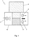
- a suitable means of detection can be an IR detection arrangement 1 with one single IR-transmitter 3 and first and second detectors 5, 7 instead of only one, as in conventional systems.
- the first detector 5 together with the IR-transmitter 3 for detecting product availability is proven technology and has been used before in detection systems.
- a second detector 7 is used to detect whether an exchangeable supply pack 9 comprising a doser 11 is in place.
- the detection arrangement 1 is part of a system that includes a beverage dispensing machine (not shown, but conventional) and at least one exchangeable supply pack comprising the doser 11.
- Such machines comprise at least one first or machine interface 13 for receiving at least one exchangeable supply pack 9 at at least one position.
- the doser 11 comprises a fluid connector and a dosing mechanism, such as a pump (not shown), and acts as a second or pack interface.
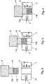
- a full exchangeable supply pack 9 comprising a doser 11 is not yet received between the transmitter 3 and the first and second detectors 5 and 7.
- Each of the first and second detectors is now exposed to the unobstructed radiation of the transmitter 3. This is characteristic for a situation that no pack is present.
- the doser 11 acts as a second or pack interface for cooperating with the first, or machine interface 13.
- FIG 3 a full exchangeable supply pack 9 is shown whereby the doser 11 of the supply pack 9 is partly inserted between the transmitter 3 and the first detector 5.
- the doser 11 has an upper part 11A that is substantially transparent.
- the doser 11 further has a lower part 11B.
- the lower part 11B of the doser 11 is substantially opaque.
- Figure 4 it is shown that the full pack 9 is properly inserted, with the upper part 11A facing the first detector 5 and the lower part 11B facing the second detector 7.
- the pack 9 is full and thus filled with a liquid product.
- the upper part 11A is filled with the liquid contents of the pack 9.
- Light emitted from the transmitter 3 is detected by the first detector 5 through the substantially transparent upper part 11A and the translucency of the liquid. This results in a signal generated by the first detector that is below a threshold typical for liquid detection (product availability).
- the second detector 7 receives no radiation from the transmitter 3, due to the opacity of the lower part 11B of the doser 11. This can be interpreted as a properly inserted full pack.
- Figure 5 the same situation as in Figure 4 is shown, except that here the pack 9 has reached an empty state.
- the partly translucent liquid product has sank below the level of the first detector 5, which now receives radiation from the transmitter 3 that is only obstructed by the transparent outer wall of the upper part 11A. This results in a different signal being generated by the first detector 5 that is above a predefined threshold, typical for an empty upper part 11A.
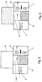
- the pack 9 is additionally provided with a removable or pierceable seal 15, which separates the upper part 11A from the main body of the pack 9 that forms the actual fluid container.
- This seal 15 covers the outlet opening of the actual fluid container, and is automatically broached by mechanical piercing or pushing out of the removable seal 15 upon full engagement of the doser 11 with the machine interface 13.
- the removal of the seal 15 has not been properly performed and no liquid has consequently entered the upper part 11A. This results in a combined reading of the first and second detectors 5 and 7 that differs from that in the situation of Figure 4 and hence an unsuccessful broaching of the pack 9 can be detected.
- the combined reading of the first and second detectors 5 and 7 is the same as in the situation of an emptied pack ( Figure 5 ), but the non-broached diagnosis can be related to the directly preceding pack insertion action having resulted in various changes of the detector readings.
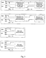
- Table 1 First detector (5) Second detector (7) Pack (9) Below threshold Below threshold Present and full Below threshold Above threshold Misplaced or in process of placement/ removal Above threshold Below threshold Empty or not broached Above threshold Above threshold No pack present
- non-broached and empty-pack diagnosis can also be related to a period of time that has lapsed after the appliance was last switched on.
- Figures 8 and 9 show an alternative embodiment in side and in perspective view.
- This embodiment is a doser according to the principles as disclosed in WO 2011/0377464 .
- the two required elements are positioned besides the in and outlet of the doser that comprises a fluid connector and a dosing mechanism, such as a pump (not shown).
- the doser 11 has an upper part 11A that is substantially transparent, and that is filled with the liquid contents of the pack 9 (not shown).
- the doser 11 further has a lower part 11B.
- the lower part 11B of the doser 11 is substantially opaque.
- Figure 9 shows the spout 17 for connecting the doser 11 to the exchangeable supply pack.
- Figure 10 shows a supply detection arrangement 1 according to the invention wherein the doser according to Figures 8 and 9 fits. It clearly shows the transmitter 3 and the first and second detectors 5, 7.
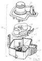
- FIG. 11 An alternative doser 31 is shown in Figure 11 .
- a first substantially transparent element 49 can be seen protruding from the right hand side of the doser 31.
- a stepped/serrated feature 51 provides the optical element of the system, as will be explained below.
- the doser further includes a bottom housing 39, a pump housing 41, and a top cap 43.
- the bottom housing 39 is the main housing of the doser 31A pump accommodated in the pump housing 41 is a gear pump with a pair of mutually engaging gear pinions 45, 47.
- One of the gear pinions 45, 47 of the pair is arranged for coupling to a drive shaft of a beverage dispensing machine.
- the pump housing 41 provides the body of the gear pump and both an inlet and outlet orifices for the pump.
- an extension 55 in the fluid flow path 53 can be seen on the right hand side of the pump housing 41.
- This extension 55 functions as a flow diverter.
- This flow diverter 55 ensures that product drawn into the pump passes through the first substantially transparent element, in the present figure sample chamber 49, and hence through the field of view of an optical system to be described below. It should be understood however that the flow diverter is an optional element not essential to the operation of the optical system.
- the top cap 43 mounts to the bottom housing 39.
- the top cap 43 is used for attachment of the doser 31 to an exchangeable supply pack (not shown, but conventional).
- Figure 12 shows the doser 31 of Figure 11 in assembled condition and in position with respect to a detection arrangement.
- the end of product availability (liquid presence), in the alternative embodiment of doser 31, is physically indicated by the presence of air in the liquid product as it is dispensed.
- the detection system uses the change in refractive index between a liquid and air to amplify the presence of air in the fluid as is passes into the pump. An example of this optical effect is schematically shown in Figure 13 .
- Light from an external light source 57 is directed towards a prism 59 that forms a part of the sample chamber 49.
- the prism 59 acts as an optical element, which can be an element in any shape or form that makes use of difference in refractive index of fluids and air. It is only required that such an optical element can be utilised to alter a direction of light falling onto this optical element.
- the light from the light source 57 passes through an external wall 61, but is reflected from an internal inside wall 63 when air is in the sample chamber 49 (see Figure 13A ). The reflected light then exits the prism 59 where it is detected by a third detector, e.g. a reflection sensor 65.
- the presence of a liquid in the sample chamber 49 changes the refractive index at the internal inside wall 63 causing the light to continue into the liquid instead of being reflected.
- Light emerging from a far chamber wall 67 is detected by a first detector, e.g. transmission sensor 69.
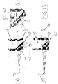
- the solid prism 59 of the schematic Figure 13 (A and B) is replaced by a series of smaller plurality of prism facets 71 shown in Figure 13C .
- the prism facets 71 form the stepped serrated feature 51 at an exterior of the inside wall 63 of the sample chamber 49.
- the whole housing of the doser might be used as the sample chamber and the prism facets could be incorporated into the housing side wall.
- the prism facets 71 act to amplify the presence of air in the sample chamber by switching light towards the reflection sensor 65 when air is present on the inside wall 63.
- a further method of improving detection is the monitoring of the various sensors during a pumping cycle. Usually such internal reflection sensors 65 could be used as static device in that the presence of air is only tested before or after the dispense cycle. The viscous and non-homogeneous nature of some liquids, especially liquid coffees, makes such an approach problematic.
- By monitoring the reflection and transmission sensors 65, 69 while the pump is operating it is possible to detect air bubbles entrained in the liquid.
- By careful design of the doser 31 it is possible to ensure that the entrained bubbles pass through the sensors' field of view.
- a further design consideration is to ensure that the bubbles are forced into contact with the internal wall 63 of each of the prism facets 71. This both improves detection and acts to clean the internal surfaces of product build up.
- a solid triangular prism 59 is used as the optical element in the system.
- the angle of the internal wall 63 is chosen as a function of the differing refractive index of air and the liquid to be measured. The angle is determined by optical analysis. Under ideal conditions with air in the sample chamber 49, all light is reflected to the reflection sensor 65 placed at 90 degrees to the incident light. Testing with various moulding techniques has shown that the optical performance is relatively unaffected by the slumping of surface features. The detection technique could therefore also use a solid prism.
- Figure 13C shows the stepped prism design, using the plurality facets 71. In practice it is preferred that a low volume of plastic be used.
- the solid prism 59 has been implemented using a series of smaller triangular facets 71. These facets 71 form a step feature 51 as shown in Figure 13C . Again the angle of the internal face or wall 63 is optimized through analysis. The size of the steps is a function of the light transmitting source 57 output angle and the reflection sensor 65 input angle. The facet steps 71 are typically at 90 degrees (but can be optimized if required). The surface finish should be flat and smooth to prevent surface scattering/lensing. Analysis has shown that a certain draft on either or both surfaces does not have a significant impact on its performance. The design is reasonably tolerant of variations due to manufacturing tolerances.
- the flow diverter 55 is optionally employed to ensure correct operation in that the product must pass in front of the detection system as it is pumped.
- the flow diverter 55 has been added in the flow path 53 of the pump to ensure that product is drawn through the sample chamber area 49.
- the flow diverter 55 does not intervene with the existing pump inlet opening size.
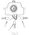
- a side view of the flow diverter is shown in Figure 15 .
- the flow diverter 55 provides several advantages, in that:
- the doser 31 forms part of an exchangeable supply pack embodied as a bag-in-box consumable.
- the pack is placed into the coffee machine/dispenser where the optical detection system is located.
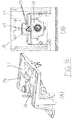
- the doser 31 is shown in Figure 16 engaged with an interface part 73 of a dispenser appliance. Thereby the doser 31 acts as a pack interface. Locating handles and other mechanisms are not shown to simplify Figure 16 .
- the optical components are located in the dispenser interface part 73 around a cavity 74 housing the sample chamber 49 with its prism facets 71. Looking at the right hand Figure 16B the light source 57 is located to the right of the prism facets 71, as will be understood in conjunction with Figures 12 and 14 .
- the reflection sensor 65 is located directly above the prism facets 71 (as illustrated in figure 16B ), while the transmission sensor 69 is located to the left of the prism facets 71.
- a further function of the optical system is to confirm that the exchangeable supply pack has been properly loaded into the dispenser appliance.
- a separate Pack-in-Place (PIP) sensor 75 is located below the transmission sensor 69 at the left of the prism facets 71, as shown in Figure 12 .
- the dispenser appliance thus include, the detection system as shown in Figure 12 and contains a number of advantageous features as will be described below.
- the transmission light source 57 for the detection system may be a light emitting diode (LED).
- LED light emitting diode
- the system will however also work at other wavelengths and has also been successfully tested at 650 nm.
- a light emitting diode (LED) with a wavelength in a range of 500 nm to 950 nm, preferably within a range of 650 nm to 880 nm is suitable.
- the preferred wavelength is a function of the product's spectral absorbance characteristics.
- the wavelength will be tuned so that the maximum attenuation is achieved when the product is present. As noted earlier the build up of product on the side walls can make this approach problematic.
- the wavelength is chosen so that maximum transmission can be achieved. This allows light entering the sample chamber 49 to penetrate any film present that might be obscuring an air void behind.
- a further advantage of an infrared light source is that it is not readily detected by a consumer during pack replacement.
- a second aspect of the transmission LED is its output beam angle. Illuminating the side wall of the sample chamber 49 with a wide angle light source will result in light propagating into and around the clear plastic side walls of the dosing assembly 31, This light can exit the side walls at various parts of the doser in an uncontrolled way and may make its way into the sensors in a rather uncontrolled manner. The result is that the sensors see some form of signal when in fact none should be present (reduced signal to noise ratio). To address this issue the output angle of the LED should be as narrow as possible and preferably around +/3 degrees (total half power beam width 6 degrees). Increasing the output angle is likely to result in reduced performance due to uncontrolled scattering of light.
- FIG 14 is a detailed view of the optical system.
- the reflection sensor 65 is chosen to match the wavelength of the LED light source 57.
- the detection angle should be reasonably wide to allow integration of the signal coming from the prism internal surface 63.
- the reception angle should however not be so broad as to allow collection of stray light from other parts of the doser 31.
- An acceptance angle of 16 to 24 degrees (corresponding to: +/-8 to +/-12 degrees half power) is recommended.
- the LED light source 57, reflection and transmission sensors 65, 69 should be aligned on the same horizontal plane.
- the reflection sensor should be located at 90 degrees to the LED axis ( Figure 12 ). The exact location of the sensor in the horizontal plane should be optimized.
- the transmission sensor 69 collects any light that passes through the sample chamber 49 when fluid product is present.
- the parameters for the transmission sensor 69 are similar to those of the reflection sensor 65 as regards wavelength and acceptance angle. Again for optimum performance the transmission sensor 69 should be located on the same axis as the LED light source 57.
- the transmission sensor 69 will detect the output of the LED light source 57 directly while the reflection sensor 65 will receive no signal at all. This sensor reading can be used by auto calibration software to look at changes in the maximum signal level, where a change may represent possible contamination of the system.
- both or either of the reflection and transmission sensors 65, 69 will receive a reduced signal level. In this case a pump priming sequence need not be initiated.
- Dynamic measurement is another feature of the detection system cooperating with the doser 31.
- Known fluid product availability sensor systems use a static system of measurement.
- An example is a float sensor in a fluid tank. In such systems the sensor allows the pump to operate so long as there is sufficient fluid available to keep the float switch closed.
- the nature of the fluid product used in the exchangeable supply pack related to the invention precludes a simple static detection system. Between dosing cycles (which may be days) a thick film of product can build up on the side walls of the sample chamber 49. This thick build up can obscure the transmission detector 69 resulting in a false indication of product availability.
- the dynamic system developed using the prism 59 i.e.
- prism facets 71 and flow diverter 55 relies primarily on the detection of air bubbles entrained in the product. These bubbles passing through the sensor system sweep up against the inner wall 63 of the prism facets 71 result in short pulses of light refracting towards the reflection sensor 65. These pulses are readily detected during a pumping cycle.
- a dynamic measurement algorithm examines the sensor system during the pump cycle and estimates the percentage of the pump cycle that contains air.
- An adjustable threshold determines when an unacceptable amount of air is passing through the system. At this point the product is flagged as no longer being available (end of pack).
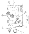
- An additional feature of the doser 31 is a second substantially opaque element 77 for wiggle and PIP sensing ( Figure 17 ).
- a splined drive shaft 79 of the dispenser pump drive must engage with pinion 45 of the pump mechanism of the doser 31 ( Figure 18 ).
- a problem can be defined in that a driven member, such as the pinion 45 of the gear pump, has to be pressed into engagement with the splined shaft 79 that will be driving the pinion 45.
- Both driving shaft 79 and pinion 45 have a moderate amount of friction.
- a solution is needed to align both without damaging the splines 81 or mating formations 83 of either part.
- This engagement is made easier if the drive shaft 79 is oscillating backwards and forwards by around +/- 40 degrees, in accordance with arrows 85, 87 indicated in Figure 18 .
- the PIP sensor 75 detects when the pinion 45 is getting close to the drive shaft 79 and when this is the case, the drive shaft 79 is wiggled slightly for a few degrees.
- Figure 17 shows the detection tab 77 for drive shaft approach and 'wiggle' initiation.
- the detection tab 77 is positioned at the bottom of the sample chamber 49. The tab 77 is sized and located to ensure that the light from the LED light source 57 to the transmission sensor 69 is obscured during lowering before the splined drive shaft 79 engages the pinion 45 of the doser 31.
- the tab 77 is used by the PIP sensor 75 for detecting pack approaching.
- the drive splines 81 of the dispenser drive shaft 79 must engage with the pump pinion 45 of the doser 31. This engagement is more readily achieved if the drive shaft 79 is rotated back and forth by a few degrees as the doser 31 engages the relevant splines 81. This oscillating rotation is referred to above as 'wiggling'.
- a further aspect of the LED light source 57 and transmission sensor 69 is that they should be located to allow them to detect the bottom of the doser sample chamber 49 before the splined shaft 79 engages the pump mechanism. This detection initiates the wiggling action.
- the tab 77 is opaque or treated to be opaque and is added to the bottom of the sample chamber 49 to ensure that the transmission sensor 69 detects the housing at the correct point in the lowering cycle.
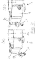
- the engagement between the splined shaft 79 and the doser housing 39 is shown in Figures 18 and 19 .
- the shaft 79 meets the doser bottom surface when the doser 31 is a first distance of (in this example) 8.8 mm above its home position.
- the splines 81 on the shaft 79 only engage with the pinion 45 at a second distance representing the last (in this example) 3.9 mm of a lowering cycle. The wiggling needs to start between the first and the second distance.
- the engagement sequence is described in more detail below.
- Figure 18 illustrates the spline engagement of the pump pinion 45 of the doser 31. while the subsequent pack-in-place detection is shown in Figure 19 .
- the further PIP sensor 75 is placed below the transmission sensor 69. This sensor is activated when the doser 31 is in the fully loaded home position. The PIP sensor 75 is located so that sufficient light from the LED light source 57 will be detected when the pack is not in place. When properly located the tab 77 on the bottom of the sample chamber 49 will obscure the PIP sensor 75 thus providing an indication that the pack is fully loaded and can be operated (see also Figure 17 ).
- the transmission sensor 69 and LED light source 57 should be on the same axis. To allow sufficient light to reach the PIP sensor 75, and to ensure that it is activated in the correct position, it may be necessary to move the transmission sensor 69 slightly off axis. In this case great care should be taken to ensure that performance of the product-availability-detection (PAD) system is not compromised. Optical ray tracing followed by testing is recommended to ensure that the system retains the desired PAD performance.
- PAD product-availability-detection
- the lowering sequence of the package with its doser 31 that is used to trigger the wiggling action and to indicate that the pack is in place is shown in Figures 17- 19 .
- a third distance of (in this example) 10 mm above the home position light to the transmission sensor 69 is already being blocked by the tab 77 on sample chamber 49.
- the shaft 79 is yet to meet with the housing 39 at this point.
- the doser 31 is shown lowering into position at the third distance of 10 mm ( Figure 19A ) and at a fourth distance of (in this example) 5 mm ( Figure 19B ).
- the transmission sensor 69 is fully obscured, but still well ahead of the second distance of 3.8 mm of the drive shaft's engagement with the gear pinion 45.
- the PIP sensor 75 is now also starting to become obscured at this point. At a fifth distance of (in this example) 2.5 mm the PIP sensor 75 has become fully obscured.
- the loading handle (not shown but conventional) can conveniently have a spring loaded 'over-centre' operation and so will assist to drive the doser 31 into its fully lowered home position.
- a pack-in-place detection is provided by emitting light and measuring the presence of the emitted light on a one light detector (7, 75), the system determines the absence or the correct/incorrect placement of the supply pack.
- a product availability detection is provided by detecting the intensity of light coming through a transparent element in the supply pack by a another light detector(5; 65, 69), the system identifies the degree of product presence in the supply pack.
Landscapes
- Physics & Mathematics (AREA)
- Electromagnetism (AREA)
- Engineering & Computer Science (AREA)
- General Physics & Mathematics (AREA)
- Food Science & Technology (AREA)
- Fluid Mechanics (AREA)
- Thermal Sciences (AREA)
- Mechanical Engineering (AREA)
- Remote Sensing (AREA)
- Radar, Positioning & Navigation (AREA)
- Computer Networks & Wireless Communication (AREA)
- Apparatus For Making Beverages (AREA)
- Devices For Dispensing Beverages (AREA)
- Beverage Vending Machines With Cups, And Gas Or Electricity Vending Machines (AREA)
- Geophysics And Detection Of Objects (AREA)
- Filling Of Jars Or Cans And Processes For Cleaning And Sealing Jars (AREA)
Applications Claiming Priority (2)
| Application Number | Priority Date | Filing Date | Title |
|---|---|---|---|
| NL2009092 | 2012-06-29 | ||
| PCT/NL2013/050477 WO2014003570A2 (en) | 2012-06-29 | 2013-07-01 | System for automated detection in beverage dispensing machines |
Publications (2)
| Publication Number | Publication Date |
|---|---|
| EP2866620A2 EP2866620A2 (en) | 2015-05-06 |
| EP2866620B1 true EP2866620B1 (en) | 2019-02-06 |
Family
ID=46982863
Family Applications (1)
| Application Number | Title | Priority Date | Filing Date |
|---|---|---|---|
| EP13739843.4A Active EP2866620B1 (en) | 2012-06-29 | 2013-07-01 | System for automated detection in beverage dispensing machines |
Country Status (17)
| Country | Link |
|---|---|
| US (2) | US9285476B2 (da) |
| EP (1) | EP2866620B1 (da) |
| JP (1) | JP6236442B2 (da) |
| KR (2) | KR102006087B1 (da) |
| CN (1) | CN104582546B (da) |
| AU (2) | AU2013281345B2 (da) |
| BR (1) | BR112014032684B1 (da) |
| CA (1) | CA2877855C (da) |
| DK (1) | DK2866620T3 (da) |
| ES (1) | ES2715606T3 (da) |
| GB (1) | GB2517391B (da) |
| HK (1) | HK1207273A1 (da) |
| MX (1) | MX355629B (da) |
| NZ (1) | NZ704198A (da) |
| RU (2) | RU2627213C2 (da) |
| WO (1) | WO2014003570A2 (da) |
| ZA (1) | ZA201500636B (da) |
Families Citing this family (18)
| Publication number | Priority date | Publication date | Assignee | Title |
|---|---|---|---|---|
| DK2866620T3 (da) | 2012-06-29 | 2019-04-01 | Douwe Egberts Bv | System til automatisk detektering i drikkevareaftapningsmaskiner |
| KR102301858B1 (ko) * | 2014-01-03 | 2021-09-15 | 코닌클리케 도우베 에그베르츠 비.브이. | 음료 배출 기기들 내에 자동화된 감지를 위한 시스템 |
| NL2013984B1 (en) | 2014-12-15 | 2016-10-11 | Douwe Egberts Bv | Dosing pump device for dosing metered amounts of a liquid product. |
| EP3232873B1 (en) * | 2014-12-15 | 2019-01-30 | Koninklijke Douwe Egberts B.V. | Unit, device and system for preparing beverage consumptions |
| NL2013985B1 (en) | 2014-12-15 | 2016-10-11 | Douwe Egberts Bv | Ceramic valve unit for a beverage machine. |
| BR112017014297B1 (pt) | 2015-01-02 | 2021-11-16 | Koninklijke Douwe Egberts B.V. | Método para preparar um concentrado de café, e, concentrado de café |
| MX377045B (es) | 2015-01-02 | 2025-03-07 | Douwe Egberts Bv | Concentrado de expreso líquido. |
| US9945711B2 (en) * | 2016-02-05 | 2018-04-17 | Pepsico, Inc. | Infrared sensor assembly for ingredient level detection in beverage dispensers |
| TWI595253B (zh) * | 2016-08-16 | 2017-08-11 | 原相科技股份有限公司 | 可用來判斷參考物件或光源相對位置的光學偵測裝置 |
| US10072962B2 (en) | 2016-07-05 | 2018-09-11 | Ecolab Usa Inc. | Liquid out-of-product alarm system and method |
| JP6822897B2 (ja) * | 2017-05-19 | 2021-01-27 | サンデン・リテールシステム株式会社 | 飲料供給装置 |
| US10779678B2 (en) * | 2017-06-01 | 2020-09-22 | Wei-Hsiang Hsu | Automatic handmade drink brewing packing equipment |
| DE102017214006A1 (de) * | 2017-08-10 | 2019-02-14 | BSH Hausgeräte GmbH | Heißgetränkezubereitungsvorrichtung |
| CN111374516B (zh) * | 2018-12-28 | 2021-12-03 | 浙江苏泊尔家电制造有限公司 | 烹饪器具和烹饪方法 |
| CN109832947B (zh) * | 2019-02-26 | 2021-08-03 | 厦门小马智泡科技有限公司 | 一种具有识别功能的茶饮机及其操作方法、识别方法 |
| IT201900024847A1 (it) | 2019-12-19 | 2021-06-19 | Delonghi Appliances Srl | Erogatore di prodotto sfuso |
| EP3845098A1 (en) * | 2019-12-30 | 2021-07-07 | BSH Hausgeräte GmbH | A coffee machine and a coffee beans container for a coffee machine |
| BE1030981B1 (nl) * | 2022-10-21 | 2024-05-27 | Labrints Bvba | Sensorbord en werkwijze voor bepaling van een type van een drank in een houder en een verwarmings- en/of opschuimtoestel met dergelijk sensorbord |
Family Cites Families (28)
| Publication number | Priority date | Publication date | Assignee | Title |
|---|---|---|---|---|
| US4182451A (en) * | 1978-05-30 | 1980-01-08 | Specialty Brands, Inc. | Container level height detector |
| DE3240047A1 (de) * | 1982-10-28 | 1984-05-03 | Bosch-Siemens Hausgeräte GmbH, 7000 Stuttgart | Vorrichtung in wasch- oder spuelmaschinen |
| GB8424101D0 (en) * | 1984-09-24 | 1984-10-31 | Vi Tal Hospital Products Ltd | Air-in-line detector |
| US5166741A (en) * | 1991-04-29 | 1992-11-24 | Motorola, Inc. | Optoelectronic speed/direction detector |
| JP3429345B2 (ja) * | 1993-11-30 | 2003-07-22 | セファテクノロジー株式会社 | 光投射位置制御装置および透明容器内試料の分量測定装置 |
| US5997121A (en) * | 1995-12-14 | 1999-12-07 | Xerox Corporation | Sensing system for detecting presence of an ink container and level of ink therein |
| GB9722711D0 (en) * | 1997-10-29 | 1997-12-24 | Mcgill Shane R | Food blending apparatus |
| ES2276670T3 (es) * | 1999-03-19 | 2007-07-01 | Titech Visionsort As | Inspeccion de materiales. |
| GB0316778D0 (en) | 2003-07-17 | 2003-08-20 | Mars Inc | Semi-automatic beverage making apparatus |
| GB2411105B (en) * | 2004-02-17 | 2006-08-30 | Kraft Foods R & D Inc | An insert and a system for the preparation of beverages |
| FR2874164B1 (fr) * | 2004-08-10 | 2006-10-06 | Cie Mediterraneenne Des Cafes | Dispositif de production de boisson avec moyen de detection |
| CN102556924B (zh) | 2004-12-14 | 2015-10-07 | 雀巢技术公司 | 用于控制饮料自动售货机例如咖啡机内的杯子填充的设备和方法 |
| US7400407B2 (en) | 2005-08-31 | 2008-07-15 | Avago Technologies Ecbu Ip Pte Ltd | Meter for measuring the turbidity of fluids using reflected light |
| NL1031010C2 (nl) * | 2006-01-26 | 2007-07-27 | Bravilor Holding Bv | Vultoestanddetectie-inrichting voor poedervormig materiaal en werkwijze voor het detecteren van een vultoestand in een opslageenheid. |
| ITMI20060395A1 (it) * | 2006-03-06 | 2007-09-07 | Bianchi Vending S P A | Dispositivo di rilevamento particolarmente per distributori automatici di bevande e distributiore automatico di bevande dotato di dispositivo ri rilevamento |
| CN200942041Y (zh) * | 2006-08-28 | 2007-09-05 | 深圳市和而泰电子科技有限公司 | 具有锅体自动检测保护装置的搅拌机 |
| PT1946684E (pt) * | 2007-01-19 | 2012-04-27 | Nestec Sa | Máquina autónoma de distribuição de alimentos e bebidas |
| GB2447024A (en) * | 2007-02-27 | 2008-09-03 | Kraft Foods R & D Inc | A dispensing machine for hot or cold drinks |
| CL2008002963A1 (es) * | 2007-10-04 | 2010-01-22 | Nestec Sa | Dispositivo calentador para una maquina para la preparacion de alimento liquido o bebida, que comprende una unidad termica con una masa metalica, a traves de la cual circula el liquido, y acumula calor y lo suministra al liquido, y tiene uno o mas componentes electricos asegurados en forma rigida a la unidad termica; y maquina. |
| DK2317898T3 (da) * | 2008-07-14 | 2012-10-15 | Nestec Sa | Vandcirkulationssystem til en driktilberedningsindretning |
| DE102008055949B4 (de) * | 2008-11-05 | 2010-12-23 | Siemens Aktiengesellschaft | Optische Erfassungseinheit für Objekte |
| DK2403386T3 (da) * | 2009-02-17 | 2013-11-11 | Koninkl Douwe Egberts Bv | Kaffebønneemballagepatron samt kaffedriksystem indeholdende denne |
| BR112012000003A2 (pt) * | 2009-07-03 | 2019-09-24 | Nestec Sa | Método para identificar cápsulas em um dispositivo de produção de bebida com identificador magneticamente responsivo |
| ES2440069T3 (es) * | 2009-09-24 | 2014-01-27 | Koninklijke Douwe Egberts B.V. | Cartucho de bebida |
| US20110075630A1 (en) | 2009-09-25 | 2011-03-31 | Eilon Riess | Enabling inter frequency assignment scanning while remaining at one frequency |
| NL2003676C2 (en) | 2009-10-20 | 2011-04-21 | Sara Lee De Nv | Fluid packaging container. |
| EP2345352A1 (en) * | 2010-01-19 | 2011-07-20 | Nestec S.A. | Method for providing information to a user from a capsule for the preparation of a beverage using a code |
| DK2866620T3 (da) | 2012-06-29 | 2019-04-01 | Douwe Egberts Bv | System til automatisk detektering i drikkevareaftapningsmaskiner |
-
2013
- 2013-07-01 DK DK13739843.4T patent/DK2866620T3/da active
- 2013-07-01 GB GB1423305.0A patent/GB2517391B/en active Active
- 2013-07-01 KR KR1020177008794A patent/KR102006087B1/ko active Active
- 2013-07-01 RU RU2015102794A patent/RU2627213C2/ru active
- 2013-07-01 EP EP13739843.4A patent/EP2866620B1/en active Active
- 2013-07-01 KR KR1020157002536A patent/KR101724216B1/ko active Active
- 2013-07-01 BR BR112014032684-3A patent/BR112014032684B1/pt active IP Right Grant
- 2013-07-01 MX MX2015000095A patent/MX355629B/es active IP Right Grant
- 2013-07-01 JP JP2015520087A patent/JP6236442B2/ja active Active
- 2013-07-01 CN CN201380045134.9A patent/CN104582546B/zh active Active
- 2013-07-01 NZ NZ704198A patent/NZ704198A/en not_active IP Right Cessation
- 2013-07-01 WO PCT/NL2013/050477 patent/WO2014003570A2/en not_active Ceased
- 2013-07-01 AU AU2013281345A patent/AU2013281345B2/en active Active
- 2013-07-01 HK HK15107927.6A patent/HK1207273A1/xx unknown
- 2013-07-01 ES ES13739843T patent/ES2715606T3/es active Active
- 2013-07-01 RU RU2017126726A patent/RU2751428C2/ru active
- 2013-07-01 CA CA2877855A patent/CA2877855C/en active Active
-
2014
- 2014-12-23 US US14/581,149 patent/US9285476B2/en active Active
-
2015
- 2015-01-28 ZA ZA2015/00636A patent/ZA201500636B/en unknown
-
2016
- 2016-02-10 US US15/040,834 patent/US9677915B2/en active Active
-
2017
- 2017-02-20 AU AU2017201129A patent/AU2017201129B2/en active Active
Non-Patent Citations (1)
| Title |
|---|
| None * |
Also Published As
Similar Documents
| Publication | Publication Date | Title |
|---|---|---|
| EP2866620B1 (en) | System for automated detection in beverage dispensing machines | |
| EP2228633B1 (en) | Optical level detector for a beverage machine | |
| US10799058B2 (en) | System for automated detection in beverage dispensing machines | |
| HK1148346A (en) | Optical level detector for a beverage machine |
Legal Events
| Date | Code | Title | Description |
|---|---|---|---|
| PUAI | Public reference made under article 153(3) epc to a published international application that has entered the european phase |
Free format text: ORIGINAL CODE: 0009012 |
|
| 17P | Request for examination filed |
Effective date: 20150127 |
|
| AK | Designated contracting states |
Kind code of ref document: A2 Designated state(s): AL AT BE BG CH CY CZ DE DK EE ES FI FR GB GR HR HU IE IS IT LI LT LU LV MC MK MT NL NO PL PT RO RS SE SI SK SM TR |
|
| AX | Request for extension of the european patent |
Extension state: BA ME |
|
| DAX | Request for extension of the european patent (deleted) | ||
| GRAP | Despatch of communication of intention to grant a patent |
Free format text: ORIGINAL CODE: EPIDOSNIGR1 |
|
| STAA | Information on the status of an ep patent application or granted ep patent |
Free format text: STATUS: GRANT OF PATENT IS INTENDED |
|
| INTG | Intention to grant announced |
Effective date: 20180824 |
|
| GRAS | Grant fee paid |
Free format text: ORIGINAL CODE: EPIDOSNIGR3 |
|
| GRAA | (expected) grant |
Free format text: ORIGINAL CODE: 0009210 |
|
| STAA | Information on the status of an ep patent application or granted ep patent |
Free format text: STATUS: THE PATENT HAS BEEN GRANTED |
|
| AK | Designated contracting states |
Kind code of ref document: B1 Designated state(s): AL AT BE BG CH CY CZ DE DK EE ES FI FR GB GR HR HU IE IS IT LI LT LU LV MC MK MT NL NO PL PT RO RS SE SI SK SM TR |
|
| REG | Reference to a national code |
Ref country code: GB Ref legal event code: FG4D |
|
| REG | Reference to a national code |
Ref country code: CH Ref legal event code: EP Ref country code: AT Ref legal event code: REF Ref document number: 1094317 Country of ref document: AT Kind code of ref document: T Effective date: 20190215 |
|
| REG | Reference to a national code |
Ref country code: DE Ref legal event code: R096 Ref document number: 602013050493 Country of ref document: DE |
|
| REG | Reference to a national code |
Ref country code: IE Ref legal event code: FG4D |
|
| REG | Reference to a national code |
Ref country code: DK Ref legal event code: T3 Effective date: 20190325 |
|
| REG | Reference to a national code |
Ref country code: NL Ref legal event code: FP |
|
| REG | Reference to a national code |
Ref country code: NO Ref legal event code: T2 Effective date: 20190206 |
|
| REG | Reference to a national code |
Ref country code: ES Ref legal event code: FG2A Ref document number: 2715606 Country of ref document: ES Kind code of ref document: T3 Effective date: 20190605 |
|
| REG | Reference to a national code |
Ref country code: LT Ref legal event code: MG4D |
|
| PG25 | Lapsed in a contracting state [announced via postgrant information from national office to epo] |
Ref country code: SE Free format text: LAPSE BECAUSE OF FAILURE TO SUBMIT A TRANSLATION OF THE DESCRIPTION OR TO PAY THE FEE WITHIN THE PRESCRIBED TIME-LIMIT Effective date: 20190206 Ref country code: PT Free format text: LAPSE BECAUSE OF FAILURE TO SUBMIT A TRANSLATION OF THE DESCRIPTION OR TO PAY THE FEE WITHIN THE PRESCRIBED TIME-LIMIT Effective date: 20190606 Ref country code: FI Free format text: LAPSE BECAUSE OF FAILURE TO SUBMIT A TRANSLATION OF THE DESCRIPTION OR TO PAY THE FEE WITHIN THE PRESCRIBED TIME-LIMIT Effective date: 20190206 Ref country code: LT Free format text: LAPSE BECAUSE OF FAILURE TO SUBMIT A TRANSLATION OF THE DESCRIPTION OR TO PAY THE FEE WITHIN THE PRESCRIBED TIME-LIMIT Effective date: 20190206 |
|
| REG | Reference to a national code |
Ref country code: AT Ref legal event code: MK05 Ref document number: 1094317 Country of ref document: AT Kind code of ref document: T Effective date: 20190206 |
|
| PG25 | Lapsed in a contracting state [announced via postgrant information from national office to epo] |
Ref country code: BG Free format text: LAPSE BECAUSE OF FAILURE TO SUBMIT A TRANSLATION OF THE DESCRIPTION OR TO PAY THE FEE WITHIN THE PRESCRIBED TIME-LIMIT Effective date: 20190506 Ref country code: GR Free format text: LAPSE BECAUSE OF FAILURE TO SUBMIT A TRANSLATION OF THE DESCRIPTION OR TO PAY THE FEE WITHIN THE PRESCRIBED TIME-LIMIT Effective date: 20190507 Ref country code: IS Free format text: LAPSE BECAUSE OF FAILURE TO SUBMIT A TRANSLATION OF THE DESCRIPTION OR TO PAY THE FEE WITHIN THE PRESCRIBED TIME-LIMIT Effective date: 20190606 Ref country code: HR Free format text: LAPSE BECAUSE OF FAILURE TO SUBMIT A TRANSLATION OF THE DESCRIPTION OR TO PAY THE FEE WITHIN THE PRESCRIBED TIME-LIMIT Effective date: 20190206 Ref country code: LV Free format text: LAPSE BECAUSE OF FAILURE TO SUBMIT A TRANSLATION OF THE DESCRIPTION OR TO PAY THE FEE WITHIN THE PRESCRIBED TIME-LIMIT Effective date: 20190206 Ref country code: RS Free format text: LAPSE BECAUSE OF FAILURE TO SUBMIT A TRANSLATION OF THE DESCRIPTION OR TO PAY THE FEE WITHIN THE PRESCRIBED TIME-LIMIT Effective date: 20190206 |
|
| PG25 | Lapsed in a contracting state [announced via postgrant information from national office to epo] |
Ref country code: RO Free format text: LAPSE BECAUSE OF FAILURE TO SUBMIT A TRANSLATION OF THE DESCRIPTION OR TO PAY THE FEE WITHIN THE PRESCRIBED TIME-LIMIT Effective date: 20190206 Ref country code: EE Free format text: LAPSE BECAUSE OF FAILURE TO SUBMIT A TRANSLATION OF THE DESCRIPTION OR TO PAY THE FEE WITHIN THE PRESCRIBED TIME-LIMIT Effective date: 20190206 Ref country code: CZ Free format text: LAPSE BECAUSE OF FAILURE TO SUBMIT A TRANSLATION OF THE DESCRIPTION OR TO PAY THE FEE WITHIN THE PRESCRIBED TIME-LIMIT Effective date: 20190206 Ref country code: AL Free format text: LAPSE BECAUSE OF FAILURE TO SUBMIT A TRANSLATION OF THE DESCRIPTION OR TO PAY THE FEE WITHIN THE PRESCRIBED TIME-LIMIT Effective date: 20190206 Ref country code: SK Free format text: LAPSE BECAUSE OF FAILURE TO SUBMIT A TRANSLATION OF THE DESCRIPTION OR TO PAY THE FEE WITHIN THE PRESCRIBED TIME-LIMIT Effective date: 20190206 |
|
| REG | Reference to a national code |
Ref country code: DE Ref legal event code: R097 Ref document number: 602013050493 Country of ref document: DE |
|
| PG25 | Lapsed in a contracting state [announced via postgrant information from national office to epo] |
Ref country code: PL Free format text: LAPSE BECAUSE OF FAILURE TO SUBMIT A TRANSLATION OF THE DESCRIPTION OR TO PAY THE FEE WITHIN THE PRESCRIBED TIME-LIMIT Effective date: 20190206 Ref country code: SM Free format text: LAPSE BECAUSE OF FAILURE TO SUBMIT A TRANSLATION OF THE DESCRIPTION OR TO PAY THE FEE WITHIN THE PRESCRIBED TIME-LIMIT Effective date: 20190206 |
|
| PLBE | No opposition filed within time limit |
Free format text: ORIGINAL CODE: 0009261 |
|
| STAA | Information on the status of an ep patent application or granted ep patent |
Free format text: STATUS: NO OPPOSITION FILED WITHIN TIME LIMIT |
|
| PG25 | Lapsed in a contracting state [announced via postgrant information from national office to epo] |
Ref country code: AT Free format text: LAPSE BECAUSE OF FAILURE TO SUBMIT A TRANSLATION OF THE DESCRIPTION OR TO PAY THE FEE WITHIN THE PRESCRIBED TIME-LIMIT Effective date: 20190206 |
|
| 26N | No opposition filed |
Effective date: 20191107 |
|
| PG25 | Lapsed in a contracting state [announced via postgrant information from national office to epo] |
Ref country code: SI Free format text: LAPSE BECAUSE OF FAILURE TO SUBMIT A TRANSLATION OF THE DESCRIPTION OR TO PAY THE FEE WITHIN THE PRESCRIBED TIME-LIMIT Effective date: 20190206 Ref country code: MC Free format text: LAPSE BECAUSE OF FAILURE TO SUBMIT A TRANSLATION OF THE DESCRIPTION OR TO PAY THE FEE WITHIN THE PRESCRIBED TIME-LIMIT Effective date: 20190206 |
|
| PG25 | Lapsed in a contracting state [announced via postgrant information from national office to epo] |
Ref country code: TR Free format text: LAPSE BECAUSE OF FAILURE TO SUBMIT A TRANSLATION OF THE DESCRIPTION OR TO PAY THE FEE WITHIN THE PRESCRIBED TIME-LIMIT Effective date: 20190206 |
|
| PG25 | Lapsed in a contracting state [announced via postgrant information from national office to epo] |
Ref country code: LU Free format text: LAPSE BECAUSE OF NON-PAYMENT OF DUE FEES Effective date: 20190701 |
|
| PG25 | Lapsed in a contracting state [announced via postgrant information from national office to epo] |
Ref country code: IE Free format text: LAPSE BECAUSE OF NON-PAYMENT OF DUE FEES Effective date: 20190701 |
|
| PG25 | Lapsed in a contracting state [announced via postgrant information from national office to epo] |
Ref country code: CY Free format text: LAPSE BECAUSE OF FAILURE TO SUBMIT A TRANSLATION OF THE DESCRIPTION OR TO PAY THE FEE WITHIN THE PRESCRIBED TIME-LIMIT Effective date: 20190206 |
|
| PG25 | Lapsed in a contracting state [announced via postgrant information from national office to epo] |
Ref country code: MT Free format text: LAPSE BECAUSE OF FAILURE TO SUBMIT A TRANSLATION OF THE DESCRIPTION OR TO PAY THE FEE WITHIN THE PRESCRIBED TIME-LIMIT Effective date: 20190206 Ref country code: HU Free format text: LAPSE BECAUSE OF FAILURE TO SUBMIT A TRANSLATION OF THE DESCRIPTION OR TO PAY THE FEE WITHIN THE PRESCRIBED TIME-LIMIT; INVALID AB INITIO Effective date: 20130701 |
|
| PG25 | Lapsed in a contracting state [announced via postgrant information from national office to epo] |
Ref country code: MK Free format text: LAPSE BECAUSE OF FAILURE TO SUBMIT A TRANSLATION OF THE DESCRIPTION OR TO PAY THE FEE WITHIN THE PRESCRIBED TIME-LIMIT Effective date: 20190206 |
|
| P01 | Opt-out of the competence of the unified patent court (upc) registered |
Effective date: 20230505 |
|
| PGFP | Annual fee paid to national office [announced via postgrant information from national office to epo] |
Ref country code: DK Payment date: 20240725 Year of fee payment: 12 |
|
| PGFP | Annual fee paid to national office [announced via postgrant information from national office to epo] |
Ref country code: NO Payment date: 20240729 Year of fee payment: 12 |
|
| PGFP | Annual fee paid to national office [announced via postgrant information from national office to epo] |
Ref country code: NL Payment date: 20250726 Year of fee payment: 13 |
|
| PGFP | Annual fee paid to national office [announced via postgrant information from national office to epo] |
Ref country code: ES Payment date: 20250801 Year of fee payment: 13 |
|
| PGFP | Annual fee paid to national office [announced via postgrant information from national office to epo] |
Ref country code: DE Payment date: 20250729 Year of fee payment: 13 |
|
| PGFP | Annual fee paid to national office [announced via postgrant information from national office to epo] |
Ref country code: IT Payment date: 20250721 Year of fee payment: 13 |
|
| PGFP | Annual fee paid to national office [announced via postgrant information from national office to epo] |
Ref country code: BE Payment date: 20250728 Year of fee payment: 13 Ref country code: GB Payment date: 20250728 Year of fee payment: 13 |
|
| PGFP | Annual fee paid to national office [announced via postgrant information from national office to epo] |
Ref country code: FR Payment date: 20250725 Year of fee payment: 13 |
|
| PGFP | Annual fee paid to national office [announced via postgrant information from national office to epo] |
Ref country code: CH Payment date: 20250801 Year of fee payment: 13 |
|
| REG | Reference to a national code |
Ref country code: DK Ref legal event code: EBP Effective date: 20250731 |
|
| PG25 | Lapsed in a contracting state [announced via postgrant information from national office to epo] |
Ref country code: NO Free format text: LAPSE BECAUSE OF NON-PAYMENT OF DUE FEES Effective date: 20250731 |