EP2866906B1 - Ensemble de dilatation thermique pour système d'extinction d'incendie par brouillard d'eau - Google Patents
Ensemble de dilatation thermique pour système d'extinction d'incendie par brouillard d'eau Download PDFInfo
- Publication number
- EP2866906B1 EP2866906B1 EP12766112.2A EP12766112A EP2866906B1 EP 2866906 B1 EP2866906 B1 EP 2866906B1 EP 12766112 A EP12766112 A EP 12766112A EP 2866906 B1 EP2866906 B1 EP 2866906B1
- Authority
- EP
- European Patent Office
- Prior art keywords
- extinguishing medium
- thermal expansion
- antifreeze
- supply line
- threshold
- Prior art date
- Legal status (The legal status is an assumption and is not a legal conclusion. Google has not performed a legal analysis and makes no representation as to the accuracy of the status listed.)
- Active
Links
Images



Classifications
-
- A—HUMAN NECESSITIES
- A62—LIFE-SAVING; FIRE-FIGHTING
- A62C—FIRE-FIGHTING
- A62C35/00—Permanently-installed equipment
- A62C35/58—Pipe-line systems
- A62C35/68—Details, e.g. of pipes or valve systems
-
- A—HUMAN NECESSITIES
- A62—LIFE-SAVING; FIRE-FIGHTING
- A62C—FIRE-FIGHTING
- A62C35/00—Permanently-installed equipment
- A62C35/58—Pipe-line systems
- A62C35/60—Pipe-line systems wet, i.e. containing extinguishing material even when not in use
Definitions
- the invention relates generally to fire suppression systems and, more particularly, to the thermal expansion of a fluid in the fire suppression system.
- Conventional fire suppression systems typically involve sprinklers positioned strategically within an area where fire protection is desired, such as inside a building.
- the sprinklers remain inactive most of the time.
- many systems include fire suppression fluid within the conduits that supply the sprinklers. The fluid is pressurized and it is necessary to maintain an adequate seal to prevent any leaks at the sprinklers or system joints while they are inactive.
- fire suppression systems can generally be designed so that the fluid within the pipes of the system does not freeze. If the fluid does freeze, the pipes of the fire suppression system containing the fluid can be damaged or the system may be rendered inoperable. In addition, environments that cause the fluid to boil or climates susceptible to extreme temperature fluctuations may adversely affect the pipes and other components of the fire suppression system due to thermal expansion of the fluid. Mechanics periodically check the standby pressure and release excess fluid if necessary to prevent damage to current fire suppression systems. These manual checks are inefficient and time consuming.
- US 2006/243459 A1 discloses a fire protection system including a sprinkler piping system with at least one sprinkler head assembly, a water supply system, and a check valve in fluid communication with the sprinkler piping system and the water supply system.
- An antifreeze solution supply system is in fluid communication with the sprinkler piping system, with the check valve isolating the antifreeze solution from the water supply unless a fire condition occurs.
- a control is provided that is in communication with a flow detector, which detects the pressure of the antifreeze solution in the sprinkler piping system, and a pressure detector, which detects the flow of water through the check valve, and controls the flow of the antifreeze solution to the sprinkler piping system and maintains the pressure of the antifreeze solution in the sprinkler piping system unless the flow detector detects the flow of water through the check valve in which case the control stops the flow of antifreeze solution to the sprinkler piping system to limit the discharge of antifreeze solution from the fire protection system.
- an antifreeze arrangement for automatic sprinkler systems comprises a frangible membrane, secured to a bellows interposed in the water supply pipe to the sprinkler system, antifreeze solution downstream of the membrane with water upstream thereof, the membrane being one that breaks out but does not separate from the bellows when a sprinkler relieves the pressure on the downstream side.
- a fire suppression system includes at least on spray head and a drive source coupled to the at least one spray head by a supply line.
- the supply lines delivers extinguishing medium to the spray head.
- the drive source maintains a standby pressure of the extinguishing medium in the supply line when the system is inactive.
- a release line is coupled at a first end to the supply line.
- the release line includes a thermal expansion assembly.
- the thermal expansion assembly includes a pressure relief valve which is operable between an open position and a closed position, and a bleed valve, which is operable between an open position and a closed position and having a second threshold.
- the pressure relief valve is configured to open, when the standby pressure in the thermal expansion assembly exceeds the first threshold, and the bleed valve is configured to close when a flow rate in the thermal expansion assembly exceeds the second threshold.
- the thermal expansion assembly When the system is inactive and the standby pressure exceeds a first threshold, the thermal expansion assembly releases extinguishing medium from the system to reduce the standby pressure. When the system is active and the standby pressure exceeds the first threshold, the thermal expansion assembly does not release extinguishing medium from the system.
- an antifreeze expansion assembly for use in a fire suppression system including a tubular conduit including a first open end and a second closed end.
- a spring member is connected to the second end. The first end is coupled to a first portion of a supply line of the fire suppression system and a second portion of the supply line is connected to the conduit at a distance from the second end.
- a piston is disposed within the conduit and is slidable between a first position and a second position. When the piston is in the second position, the spring member is compressed and the piston does not obstruct a flow path from the first portion of the supply to line to the second portion of the supply line.
- a method for maintaining a standby pressure in a fire suppression system having a driving source coupled to a spray head by a supply line for delivering extinguishing medium thereto.
- the method includes monitoring a standby pressure in the fire suppression system.
- a thermal expansion assembly coupled to the supply line opens when the standby pressure exceeds a threshold and the driving source is inoperable. Opening of the thermal expansion assembly releases extinguishing medium and pressure from the system.
- the thermal expansion assembly is closed once the standby pressure is less than or equal to the threshold.
- a method of maintaining a standby pressure of a fire suppression system containing both antifreeze and extinguishing medium within a predetermined threshold including expanding either the antifreeze of the extinguishing medium in the system as a result of a temperature change.
- a portion of an antifreeze-extinguishing medium interface moves to accommodate the expansion.
- a thermal expansion assembly opens to release extinguishing medium from the system.
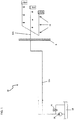
- a known fire suppression system 10 including a drive source 16 is illustrated.
- a supply line 12 extends from the drive source 16 to a plurality of spray heads 14 to supply an extinguishing medium thereto.
- the spray heads 14 include nozzles with small openings arranged to spray an aqueous liquid mist.
- the drive unit 16 is also connected to an extinguishing medium source 18, such as a pipeline network or a tank.
- the spray heads 14 of each fire suppression system 10 may be positioned in the same general area as the drive source 16, or alternatively, may be, separated from the drive source 16 by a barrier B, such as a wall for example.
- the spray heads 14 may be susceptible to extreme temperatures, such as -40°C or 60°C for example, or extreme temperature fluctuations (see FIGS. 1 and 2 ).
- the drive source 16 which includes a fire pump and a low flow pneumatic pump in one embodiment, maintains a constant pressure in the supply line 12, also referred to as a standby pressure, when the fire suppression system 10 is not active.
- the drive source 16 applies a constant pneumatic pressure at the inlet of the supply line 12, however, the drive source 16 only generates a flow if the pressure in the system is below a minimum level.
- a pressure relief valve 20 is coupled to the supply line 12 and has a threshold, for example 210 bar, such that if the standby pressure of the system 10 exceeds the threshold, the pressure will cause the relief valve 20 to open and remain open until the standby pressure falls below the threshold to an acceptable level.
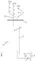
- FIG. 2 An alternate known fire suppression system 10 is illustrated in FIG. 2 .
- the portion 12b of the supply line 12 adjacent the spray heads 14 is filled with antifreeze and the portion 12a of the supply line adjacent the drive source 16 is filled with an extinguishing medium, such as water for example.
- Portions 12a and 12b of the supply line 12 connect at an antifreeze-extinguishing medium interface 60, such as a check valve for example, positioned near the barrier B to prevent mixing of the extinguishing medium and antifreeze within the system 10.
- the antifreeze-extinguishing medium interface 60 is positioned at a vertical section of the supply line 12 (see FIG. 6 ). By orienting the antifreeze-extinguishing medium interface 60 vertically, so that gravity, in conjunction with the different densities of the extinguishing medium and the antifreeze, prevents mixing of the two fluids.
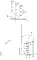
- a fire suppression system 10 additionally includes a thermal expansion assembly 30 to release additional standby pressure in the system 10 caused by thermal expansion of the fluid in the supply line 12.
- the thermal expansion assembly 30 may be included in systems 10 that use only extinguishing medium (see FIG. 1 ) or in systems 10 that use both extinguishing medium and antifreeze (see FIG. 2 ).
- a first end 33 of the release line 32 connects the thermal expansion assembly 30 to the supply line 12.
- the second end 35 of release line 32 is connected to a sewer to release some of the extinguishing medium from the supply line 12. In another embodiment, the second end 35 of the release line 32 is connected to the extinguishing medium source 18 to recycle the extinguishing medium released from the supply line 12 within the system 10.
- the thermal expansion assembly 30, shown in greater detail in FIG. 4 includes a shutoff valve 34, a filter 36, and a throttle 38.
- the shutoff valve 34 may be provided for maintenance purposes to prevent flow into the release line 32 when the valve 34 is closed. However, the shutoff valve 34 generally remains open during normal operation of the system 10 such that the extinguishing medium in the portion 12a of the supply line 12 will flow freely into the release pipe 32. After passing through the open shutoff valve 34, the extinguishing medium flows through filter 36 and the adjacent throttle 38.
- the filter 36 prevents contaminants in the supply line 12 and the extinguishing medium from interfering with the operation of the thermal expansion assembly 30 and the throttle 38 controls the flow rate of the extinguishing medium in the release line 32.
- the thermal expansion assembly 30 includes a pressure relief valve 40 disposed along the release line 32 between the throttle 38 and the second end 35.
- the relief valve 40 has a predetermined threshold, for example 45 bar, such that if the standby pressure of the system 10 exceeds the predetermined threshold, the pressure will cause the relief valve 40 to open and remain open until the standby pressure falls below the predetermined threshold.
- the predetermined threshold of the relief valve is less than the pressure required to activate an alarm (not shown) in the fire suppression system 10.
- the driving source 16 operates, such as when the fire suppression system 10 is active, the pressure in the system is greater than the predetermined threshold of the pressure relief valve 40. Therefore the pressure relief valve 40 will remain open as long as the driving source 16 is active.
- a bleed valve 42 including a piston 44 connected to a biasing member 46, such as a spring for example.
- the biasing member 46 biases the piston 44 into an open position, to allow the extinguishing medium to flow through the bleed valve 42. If the flow rate of the extinguishing medium is above a predetermined threshold, such as 2L/min for example, the flow of the extinguishing medium will cause the piston 44 to compress the biasing member 46, thereby blocking the flow path within the release line 32.
- the predetermined threshold of the bleed valve 42 is less than the flow rate of the extinguishing medium being actively pumped into the supply line 12 by the driving source 16. Closing the bleed valve 42 while the driving source 16 is active ensures that the extinguishing medium being pumped into the supply line 12 will reach the spray heads 14 with a desired pressure.
- the thermal expansion assembly 30 maintains the standby pressure in the fire suppression system 10 within an allowable threshold.
- the drive source 16 applies a constant pressure to the extinguishing medium in the supply line 12. If a change in temperature causes the extinguishing medium to expand, the increase in pressure will open the pressure relief valve 40, thereby allowing the expanding medium to flow into the bleed valve 42. If the flow rate of the extinguishing medium is less than the threshold of the bleed valve 42, the bleed valve 42 will remain in an open position, such that the extinguishing medium will flow through the bleed valve 42 and out a second end 35 of the release line 32. Once enough extinguishing medium has been released from the supply line 12 of the system 10, the standby pressure will return to the allowable threshold, and the pressure relief valve 40 will bias closed.
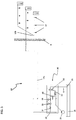
- the thermal expansion assembly 30 is electric and includes a pressure switch 48 and a valve 50, for example a directional control valve, in place of the pressure relief valve 40 and the bleed valve 42.
- the pressure relief switch 48 is coupled to the driving source 16 and to a solenoid 52 that moves the valve 50 between an open position and a closed position.
- a predetermined threshold such as 45 bar for example
- the pressure switch 48 will send a signal to the solenoid 52 to open the valve 50.
- the solenoid 52 will not open the valve 50, because the pressure in the system 10 moves the extinguishing medium and antifreeze through the supply line 12 to the spray heads 14.
- the pressure switch 48 continuously monitors the standby pressure in the system 10. If a change in temperature causes the extinguishing medium to expand within the supply line 12, the pressure switch 48 detects the increase in pressure. The pressure switch 48 will then detects the status of the driving source 16. After determining that the driving source 16 is inactive, the pressure switch 48 will generate and send a signal to the solenoid 52. In response to the signal, the solenoid 52 opens the valve 50, allowing extinguishing medium to flow therethrough. Once enough extinguishing medium has been released from the system 10, the pressure switch 48 will detect when the standby pressure of the system 10 is again within the allowable threshold. The pressure switch 48 then sends a signal to the solenoid 52 to close the valve 50.
- an antifreeze-extinguishing medium interface 60 may cooperate with the thermal expansion assembly 30 of either of the systems 10 shown in FIGS. 3 and 5 , to accommodate the thermal expansion that creates an increased standby pressure within the supply line 12.
- a known vertically oriented antifreeze-extinguishing medium interface 60 illustrated in FIG. 6 , includes a filling valve 80 near a first end and a sampling valve 82 near a second, opposite end.
- the antifreeze expands, causing extinguishing medium to be released through the thermal expansion assembly 30. If the temperature decreases causing the antifreeze in the antifreeze-extinguishing medium interface 60 to contract, the drive source 16 adds additional extinguishing medium to the supply line 12 to maintain the standby pressure at an acceptable threshold.
- Another antifreeze-extinguishing medium interface 60 shown in FIG. 7 , includes a generally horizontal tubular conduit 62 and a piston 68 disposed within the interior of the conduit 62.
- a first end 64 of the conduit 62 is connected to portion 12a of the supply line 12.
- Portion 12b of the supply line 12 is connected to the conduit 62 a distance from the second end 66. In one embodiment, the distance is at least equal to the length of the piston 62.
- the extinguishing medium contacts a first surface 70 of the piston 68 and the antifreeze contacts a second, opposite surface 72 of the piston 68.
- the piston 68 has a diameter complementary to the inner diameter of the conduit 62, allowing the piston 68 to slide within the conduit, while providing a seal that separates the extinguishing medium and the antifreeze.
- a biasing member 74 is connected to the closed second end 66 of the conduit 62.
- the piston 68 will slide within the conduit 62 to adapt to the new pressure, and extinguishing medium may be added to or released from the system 10 as necessary.
- the driving source 16 pumps the extinguishing medium through portion 12a of the supply line 12 with a pressure sufficient to move the piston 68 relative to the conduit 62.
- the piston 68 applies a pressure to the antifreeze, thereby forcing it through portion 12b of the supply line 12 to the spray heads 14.
- the piston 68 contacts and depresses the biasing member 74, such that the piston 68 is positioned between the second end 66 and the connection to portion 12b of the supply line 12. Moving the piston 68 to a position adjacent the second end 66 removes the piston 68 from the flow path, thereby allowing the extinguishing medium to flow into portion 12b of the supply line 12 and to the spray heads 14.
- the biasing member 74 will bias the piston 68 back into an inactive position towards the center of the conduit 62.
- thermal expansion assembly 30 By including a thermal expansion assembly 30 in the fire suppression system 10, manual checks of the standby pressure in the system 10 are no longer required.
- the system 10 can automatically release additional pressure from the system by removing some of the fluid from the supply line 12.
- Systems 10 including a thermal expansion assembly 30 will have improved accuracy and life because the increased pressure will reduce the occurrence of false alarms and leaks.
- the antifreeze expansion assembly 60 that may be used in conjunction with the thermal expansion assembly 30 does not rely on gravity to separate the extinguish medium and antifreeze. Consequently, the antifreeze in the system 10 does not dilute over time, regardless of how many volume changes occur in the system 10.
Landscapes
- Health & Medical Sciences (AREA)
- Public Health (AREA)
- Business, Economics & Management (AREA)
- Emergency Management (AREA)
- Fire-Extinguishing By Fire Departments, And Fire-Extinguishing Equipment And Control Thereof (AREA)
Claims (15)
- Système d'extinction d'incendie (10) comprenant :au moins une tête de pulvérisation (14) ;une source d'entraînement (16) couplée à l'au moins une tête de pulvérisation (14) par une conduite d'alimentation (12) qui fournit un milieu d'extinction à celle-ci, dans lequel la source d'entraînement (16) maintient le milieu d'extinction dans la conduite d'alimentation (12) à une pression d'attente lorsque le système (10) est inactif ;une conduite de libération (32), couplée à une première extrémité à la conduite d'alimentation (12), la conduite de libération (32) comprenant un ensemble de dilatation thermique (30) qui est configuré pour libérer un milieu d'extinction pour réduire la pression d'attente, lorsque le système (10) est inactif et que la pression d'attente dépasse une première valeur seuil, et ne pas libérer de milieu d'extinction, lorsque le système (10) est actif et que la pression d'attente dépasse la première valeur seuil,dans lequel l'ensemble de dilatation thermique (30) comprend :une soupape de limitation de pression (40) pouvant fonctionner entre une position ouverte et une position fermée, dans lequel la soupape de limitation de pression (40) est configurée pour s'ouvrir, lorsque la pression d'attente dans l'ensemble de dilatation thermique (30) dépasse la première valeur seuil ; etune soupape de purge (42) pouvant fonctionner entre une position ouverte et une position fermée et ayant une deuxième valeur seuil, dans lequel la soupape de purge (42) est configurée pour se fermer lorsqu'un débit dans l'ensemble de dilatation thermique (30) dépasse la deuxième valeur seuil.
- Système d'extinction d'incendie (10) selon la revendication 1, où la première valeur seuil est inférieure à une pression requise pour activer une alarme dans le système (10), où la première valeur seuil en particulier est une pression d'environ 45 bar.
- Système d'extinction d'incendie (10) selon la revendication 1, dans lequel une deuxième extrémité (35) de la conduite de libération (32) est reliée à un égout ou à une source de milieu d'extinction (18) pour réutilisation à l'intérieur du système d'extinction d'incendie (10).
- Système d'extinction d'incendie (10) selon la revendication 1, dans lequel la soupape de purge (42) comprend un piston (44) couplé à un élément de sollicitation (46), dans lequel lorsque la soupape de purge (42) est fermée, le piston (44) comprime l'élément de sollicitation (46), bloquant un trajet d'écoulement du milieu d'extinction à travers l'ensemble de dilatation thermique (30).
- Système d'extinction d'incendie (10) selon la revendication 1, dans lequel la deuxième valeur seuil de l'ensemble de dilatation thermique (30) est inférieure au débit de la source d'entraînement (16) lorsque actif, dans lequel la deuxième valeur seuil de l'ensemble de dilatation thermique (30) en particulier est un débit d'environ 2 L/min.
- Système d'extinction d'incendie (10) selon la revendication 1, comprenant en outre une interface antigel - milieu d'extinction (60) dans la conduite d'alimentation (12), dans lequel l'interface antigel - milieu d'extinction (60) en particulier comprend :un conduit (62) comprenant une première extrémité ouverte (64) et une deuxième extrémité fermée (66) ayant un élément de sollicitation (74) qui y est relié, dans lequel la première extrémité (64) est couplée à une première portion (12a) de la conduite d'alimentation (12) et une deuxième portion (12b) de la conduite d'alimentation (12) est couplée à une ouverture dans le conduit à une distance de la deuxième extrémité (35) ;un piston (68) disposé à l'intérieur du conduit (62), coulissant entre une première position et une deuxième position, dans lequel lorsque le piston (68) est dans la deuxième position, l'élément de sollicitation (74) est comprimé, et le piston (68) n'obstrue pas un trajet d'écoulement de la première portion (12a) de la conduite d'alimentation (12) à la deuxième portion (12b) de la conduite d'alimentation (12).
- Interface antigel - milieu d'extinction (60) selon la revendication 6, dans laquelle l'élément de sollicitation (74) est un ressort et/ou dans laquelle l'élément de sollicitation (74) déplace le piston hors de la deuxième position.
- Interface antigel - milieu d'extinction (60) selon la revendication 6, dans laquelle le milieu d'extinction et l'antigel sont séparés par le piston (68), dans laquelle le piston (68) en particulier coulisse à l'intérieur du conduit (62) pour recevoir la dilatation thermique soit du milieu d'extinction soit de l'antigel.
- Interface antigel - milieu d'extinction (60) selon la revendication 6, dans laquelle lorsque le système d'extinction d'incendie (10) est actif, une pression du milieu d'extinction étant pompée dans la conduite d'alimentation (12) par la source d'entraînement (16) amène le piston (68) à coulisser de la première position à la deuxième position.
- Interface antigel - milieu d'extinction (60) selon la revendication 6, dans laquelle la distance entre la deuxième extrémité (35) et la liaison à la deuxième portion de la conduite d'alimentation (12) est environ égale à une longueur du piston (68).
- Procédé de maintien d'une pression d'attente dans un système d'extinction d'incendie (10) ayant une source d'entraînement (16) couplée à au moins une tête de pulvérisation (14) par une conduite d'alimentation (12) pour fournir un milieu d'extinction à celle-ci et un ensemble de dilatation thermique (30) couplé à la conduite d'alimentation (12) et comprenant :une soupape de limitation de pression (40) pouvant fonctionner entre une position ouverte et une position fermée, dans lequel la soupape de limitation de pression (40) est configurée pour s'ouvrir, lorsque la pression d'attente dans l'ensemble de dilatation thermique (30) dépasse la première valeur seuil ; etune soupape de purge (42) pouvant fonctionner entre une position ouverte et une position fermée, et ayant une deuxième valeur seuil, dans lequel la soupape de purge (42) est configurée pour se fermer lorsqu'un débit dans l'ensemble de dilatation thermique (30) dépasse la deuxième valeur seuil,dans lequel le procédé comprend :la génération de la pression d'attente dans le système d'extinction d'incendie (10) ;l'ouverture de l'ensemble de dilatation thermique (30) couplé à la conduite d'alimentation (12) lorsque la pression d'attente dépasse une valeur seuil et que la source d'entraînement (16) ne fonctionne pas pour libérer du milieu d'extinction et une pression de celle-ci ; etla fermeture de l'ensemble de dilatation thermique (30) une fois que la pression d'attente est inférieure ou égale à la valeur seuil.
- Procédé selon la revendication 11, dans lequel la valeur seuil est une pression d'environ 45 bar.
- Procédé selon la revendication 11, dans lequel le milieu d'extinction est libéré dans un réservoir de milieu d'extinction (18) pour réutilisation dans le système (10), ou dans lequel le milieu d'extinction est libéré à l'extérieur du système (10).
- Procédé selon la revendication 11, dans lequel l'ensemble de dilatation thermique (30) est ouvert hydrauliquement ou électriquement.
- Procédé selon la revendication 11 comprenant en outre :la dilatation soit de l'antigel soit du milieu d'extinction dans le système (10) en tant que résultat d'un changement de température ;le déplacement d'une portion (68) d'une interface antigel - milieu d'extinction (60) pour recevoir la dilatation soit de l'antigel soit du milieu d'extinction ; etl'ouverture d'un ensemble de dilatation thermique (30) pour libérer un milieu d'extinction du système (10), dans lequel l'interface antigel - milieu d'extinction (60) en particulier comprend un piston (68) coulissant à l'intérieur d'un conduit (62), dans lequel le piston (68) en particulier sépare l'antigel et le milieu d'extinction.
Applications Claiming Priority (1)
| Application Number | Priority Date | Filing Date | Title |
|---|---|---|---|
| PCT/FI2012/050677 WO2014001604A1 (fr) | 2012-06-28 | 2012-06-28 | Ensemble de dilatation thermique pour système d'extinction d'incendie par brouillard d'eau |
Publications (2)
| Publication Number | Publication Date |
|---|---|
| EP2866906A1 EP2866906A1 (fr) | 2015-05-06 |
| EP2866906B1 true EP2866906B1 (fr) | 2019-02-13 |
Family
ID=46934612
Family Applications (1)
| Application Number | Title | Priority Date | Filing Date |
|---|---|---|---|
| EP12766112.2A Active EP2866906B1 (fr) | 2012-06-28 | 2012-06-28 | Ensemble de dilatation thermique pour système d'extinction d'incendie par brouillard d'eau |
Country Status (6)
| Country | Link |
|---|---|
| US (1) | US20150321036A1 (fr) |
| EP (1) | EP2866906B1 (fr) |
| KR (1) | KR101938885B1 (fr) |
| CN (1) | CN104540556B (fr) |
| ES (1) | ES2724201T3 (fr) |
| WO (1) | WO2014001604A1 (fr) |
Families Citing this family (21)
| Publication number | Priority date | Publication date | Assignee | Title |
|---|---|---|---|---|
| CN107537125A (zh) * | 2016-06-28 | 2018-01-05 | 江苏华燕船舶装备有限公司 | 用于co2灭火系统装置的延时单元及其工作方法 |
| US20240157180A1 (en) | 2021-02-04 | 2024-05-16 | Mighty Fire Breaker Llc | Method of and kit for installing and operating a wildfire defense spraying system on a property parcel for proactively spraying environmentally-clean liquid fire inhibitor thereover to inhibit fire ignition and flame spread caused by wind-driven wildfire embers |
| US11865394B2 (en) | 2017-12-03 | 2024-01-09 | Mighty Fire Breaker Llc | Environmentally-clean biodegradable water-based concentrates for producing fire inhibiting and fire extinguishing liquids for fighting class A and class B fires |
| US11865390B2 (en) | 2017-12-03 | 2024-01-09 | Mighty Fire Breaker Llc | Environmentally-clean water-based fire inhibiting biochemical compositions, and methods of and apparatus for applying the same to protect property against wildfire |
| US10653904B2 (en) | 2017-12-02 | 2020-05-19 | M-Fire Holdings, Llc | Methods of suppressing wild fires raging across regions of land in the direction of prevailing winds by forming anti-fire (AF) chemical fire-breaking systems using environmentally clean anti-fire (AF) liquid spray applied using GPS-tracking techniques |
| US11395931B2 (en) | 2017-12-02 | 2022-07-26 | Mighty Fire Breaker Llc | Method of and system network for managing the application of fire and smoke inhibiting compositions on ground surfaces before the incidence of wild-fires, and also thereafter, upon smoldering ambers and ashes to reduce smoke and suppress fire re-ignition |
| US10695597B2 (en) | 2017-12-02 | 2020-06-30 | M-Fire Holdings Llc | Method of and apparatus for applying fire and smoke inhibiting compositions on ground surfaces before the incidence of wild-fires, and also thereafter, upon smoldering ambers and ashes to reduce smoke and suppress fire re-ignition |
| US10814150B2 (en) | 2017-12-02 | 2020-10-27 | M-Fire Holdings Llc | Methods of and system networks for wireless management of GPS-tracked spraying systems deployed to spray property and ground surfaces with environmentally-clean wildfire inhibitor to protect and defend against wildfires |
| US10260232B1 (en) | 2017-12-02 | 2019-04-16 | M-Fire Supression, Inc. | Methods of designing and constructing Class-A fire-protected multi-story wood-framed buildings |
| US10430757B2 (en) | 2017-12-02 | 2019-10-01 | N-Fire Suppression, Inc. | Mass timber building factory system for producing prefabricated class-A fire-protected mass timber building components for use in constructing prefabricated class-A fire-protected mass timber buildings |
| US12594448B2 (en) | 2019-06-22 | 2026-04-07 | Mighty Fire Breaker Llc | Environmentally-clean aqueous-based fire extinguishing biochemical liquid concentrates for mixing with proportioned quantities of water to produce fire extinguishing water streams |
| US10332222B1 (en) | 2017-12-02 | 2019-06-25 | M-Fire Supression, Inc. | Just-in-time factory methods, system and network for prefabricating class-A fire-protected wood-framed buildings and components used to construct the same |
| US10290004B1 (en) | 2017-12-02 | 2019-05-14 | M-Fire Suppression, Inc. | Supply chain management system for supplying clean fire inhibiting chemical (CFIC) totes to a network of wood-treating lumber and prefabrication panel factories and wood-framed building construction job sites |
| US10311444B1 (en) | 2017-12-02 | 2019-06-04 | M-Fire Suppression, Inc. | Method of providing class-A fire-protection to wood-framed buildings using on-site spraying of clean fire inhibiting chemical liquid on exposed interior wood surfaces of the wood-framed buildings, and mobile computing systems for uploading fire-protection certifications and status information to a central database and remote access thereof by firefighters on job site locations during fire outbreaks on construction sites |
| US11836807B2 (en) | 2017-12-02 | 2023-12-05 | Mighty Fire Breaker Llc | System, network and methods for estimating and recording quantities of carbon securely stored in class-A fire-protected wood-framed and mass-timber buildings on construction job-sites, and class-A fire-protected wood-framed and mass timber components in factory environments |
| US11826592B2 (en) | 2018-01-09 | 2023-11-28 | Mighty Fire Breaker Llc | Process of forming strategic chemical-type wildfire breaks on ground surfaces to proactively prevent fire ignition and flame spread, and reduce the production of smoke in the presence of a wild fire |
| CN110895614A (zh) * | 2018-09-13 | 2020-03-20 | 开利公司 | 灭火系统-管路设计人工智能辅助和可视化工具 |
| US20240252866A1 (en) | 2020-03-01 | 2024-08-01 | Mighty Fire Breaker Llc | Liquid hydrocarbon sorbing article of manufacture for inhibiting fire ignition involving flammable liquid hydrocarbons, while absorbing the flammable liquid hydrocarbons when spilled on a body of water and/or land |
| US11911643B2 (en) | 2021-02-04 | 2024-02-27 | Mighty Fire Breaker Llc | Environmentally-clean fire inhibiting and extinguishing compositions and products for sorbing flammable liquids while inhibiting ignition and extinguishing fire |
| CN111840860A (zh) * | 2020-08-05 | 2020-10-30 | 上海外高桥造船有限公司 | 一种灭火系统及包含其的fpso船舶 |
| CN113629512B (zh) * | 2021-08-25 | 2023-10-24 | 安徽富煌电力装备科技有限公司 | 一种防火式分布式光伏并网柜 |
Family Cites Families (10)
| Publication number | Priority date | Publication date | Assignee | Title |
|---|---|---|---|---|
| US4326589A (en) * | 1979-05-14 | 1982-04-27 | Baldor Electric Company | Anti-freeze arrangement for sprinkler systems |
| JPS6384571A (ja) * | 1986-09-30 | 1988-04-15 | ホーチキ株式会社 | 消火設備の圧力逃し装置 |
| JPH07265456A (ja) * | 1994-03-31 | 1995-10-17 | Hochiki Corp | 消火設備 |
| FI114083B (fi) * | 2002-11-18 | 2004-08-13 | Marioff Corp Oy | Menetelmä suihkutuslaitteiston yhteydessä ja suihkutuslaitteisto |
| US7389824B2 (en) * | 2003-09-05 | 2008-06-24 | The Viking Corporation | Fire extinguishing system |
| EP1830928B1 (fr) * | 2004-11-29 | 2017-01-11 | Phoenix Firefighting Technologies SA | Systeme, notamment anti-feu, avec vannes |
| JP4885822B2 (ja) * | 2007-11-06 | 2012-02-29 | ホーチキ株式会社 | 放水継手 |
| CN201695450U (zh) * | 2010-05-04 | 2011-01-05 | 何昕彤 | 定压补水排气三功能一体机 |
| JP5603682B2 (ja) * | 2010-07-05 | 2014-10-08 | ホーチキ株式会社 | 消火栓装置 |
| CN202078683U (zh) * | 2011-04-25 | 2011-12-21 | 禹尚企业股份有限公司 | 安全释压装置 |
-
2012
- 2012-06-28 CN CN201280074145.5A patent/CN104540556B/zh active Active
- 2012-06-28 EP EP12766112.2A patent/EP2866906B1/fr active Active
- 2012-06-28 US US14/410,435 patent/US20150321036A1/en not_active Abandoned
- 2012-06-28 ES ES12766112T patent/ES2724201T3/es active Active
- 2012-06-28 WO PCT/FI2012/050677 patent/WO2014001604A1/fr not_active Ceased
- 2012-06-28 KR KR1020147035272A patent/KR101938885B1/ko active Active
Non-Patent Citations (1)
| Title |
|---|
| None * |
Also Published As
| Publication number | Publication date |
|---|---|
| WO2014001604A1 (fr) | 2014-01-03 |
| CN104540556B (zh) | 2018-10-02 |
| US20150321036A1 (en) | 2015-11-12 |
| KR101938885B1 (ko) | 2019-01-15 |
| ES2724201T3 (es) | 2019-09-09 |
| EP2866906A1 (fr) | 2015-05-06 |
| CN104540556A (zh) | 2015-04-22 |
| KR20150029643A (ko) | 2015-03-18 |
Similar Documents
| Publication | Publication Date | Title |
|---|---|---|
| EP2866906B1 (fr) | Ensemble de dilatation thermique pour système d'extinction d'incendie par brouillard d'eau | |
| US4842198A (en) | Device for damage protection against local flooding caused by sprinkler failure | |
| CN101076378B (zh) | 具有阀门的系统,特别是消防系统 | |
| US7383892B2 (en) | Preaction fire extinguishing system for ESFR cold storage applications | |
| CN217130476U (zh) | 先导致动器和灭火系统 | |
| US20180243591A1 (en) | Method and apparatus for an emergency air breathing system | |
| CN110087741B (zh) | 灭火设备阀,尤其湿式报警阀,干式报警阀或喷水阀,和具有其的灭火设备 | |
| US11013942B2 (en) | Pressure maintenance device with automatic switchover for use in a fire protection sprinkler system, and a related method | |
| US11247086B2 (en) | Pilot actuator for actuating a control valve | |
| US20120132444A1 (en) | Dry Sprinkler head | |
| JP5827151B2 (ja) | 湿式スプリンクラーシステム | |
| JP2011024792A (ja) | 流水検知装置 | |
| JP5709612B2 (ja) | スプリンクラ消火設備 | |
| KR101505897B1 (ko) | 과유량 자동차단장치를 이용한 복합 소화시스템 | |
| JP5377391B2 (ja) | スプリンクラ消火設備 | |
| JP5705026B2 (ja) | スプリンクラ消火設備及びスプリンクラ消火設備の制御方法 | |
| JP2013066532A (ja) | スプリンクラ消火設備 | |
| JP2014188302A (ja) | スプリンクラ消火設備 | |
| CN100546678C (zh) | 防误喷防冰冻开式自动喷水系统 | |
| JP5553789B2 (ja) | スプリンクラ消火設備 | |
| JP4726944B2 (ja) | 予作動式スプリンクラー設備 | |
| KR102581217B1 (ko) | 저압 습식밸브가 구비된 스프링클러 시스템 | |
| JP6482288B2 (ja) | 消火設備用バルブ | |
| JP2019111044A (ja) | スプリンクラー消火設備 | |
| KR101291182B1 (ko) | 스프링클러 알람 밸브 및 이를 이용한 소방 시스템 |
Legal Events
| Date | Code | Title | Description |
|---|---|---|---|
| PUAI | Public reference made under article 153(3) epc to a published international application that has entered the european phase |
Free format text: ORIGINAL CODE: 0009012 |
|
| 17P | Request for examination filed |
Effective date: 20150105 |
|
| AK | Designated contracting states |
Kind code of ref document: A1 Designated state(s): AL AT BE BG CH CY CZ DE DK EE ES FI FR GB GR HR HU IE IS IT LI LT LU LV MC MK MT NL NO PL PT RO RS SE SI SK SM TR |
|
| AX | Request for extension of the european patent |
Extension state: BA ME |
|
| DAX | Request for extension of the european patent (deleted) | ||
| RIC1 | Information provided on ipc code assigned before grant |
Ipc: A62C 35/68 20060101ALI20180724BHEP Ipc: A62C 35/60 20060101AFI20180724BHEP |
|
| GRAP | Despatch of communication of intention to grant a patent |
Free format text: ORIGINAL CODE: EPIDOSNIGR1 |
|
| STAA | Information on the status of an ep patent application or granted ep patent |
Free format text: STATUS: GRANT OF PATENT IS INTENDED |
|
| INTG | Intention to grant announced |
Effective date: 20180903 |
|
| GRAS | Grant fee paid |
Free format text: ORIGINAL CODE: EPIDOSNIGR3 |
|
| GRAA | (expected) grant |
Free format text: ORIGINAL CODE: 0009210 |
|
| STAA | Information on the status of an ep patent application or granted ep patent |
Free format text: STATUS: THE PATENT HAS BEEN GRANTED |
|
| AK | Designated contracting states |
Kind code of ref document: B1 Designated state(s): AL AT BE BG CH CY CZ DE DK EE ES FI FR GB GR HR HU IE IS IT LI LT LU LV MC MK MT NL NO PL PT RO RS SE SI SK SM TR |
|
| REG | Reference to a national code |
Ref country code: GB Ref legal event code: FG4D |
|
| REG | Reference to a national code |
Ref country code: CH Ref legal event code: EP Ref country code: AT Ref legal event code: REF Ref document number: 1095870 Country of ref document: AT Kind code of ref document: T Effective date: 20190215 |
|
| REG | Reference to a national code |
Ref country code: IE Ref legal event code: FG4D |
|
| REG | Reference to a national code |
Ref country code: DE Ref legal event code: R096 Ref document number: 602012056648 Country of ref document: DE |
|
| REG | Reference to a national code |
Ref country code: LT Ref legal event code: MG4D |
|
| REG | Reference to a national code |
Ref country code: NL Ref legal event code: MP Effective date: 20190213 |
|
| PG25 | Lapsed in a contracting state [announced via postgrant information from national office to epo] |
Ref country code: LT Free format text: LAPSE BECAUSE OF FAILURE TO SUBMIT A TRANSLATION OF THE DESCRIPTION OR TO PAY THE FEE WITHIN THE PRESCRIBED TIME-LIMIT Effective date: 20190213 Ref country code: NL Free format text: LAPSE BECAUSE OF FAILURE TO SUBMIT A TRANSLATION OF THE DESCRIPTION OR TO PAY THE FEE WITHIN THE PRESCRIBED TIME-LIMIT Effective date: 20190213 Ref country code: SE Free format text: LAPSE BECAUSE OF FAILURE TO SUBMIT A TRANSLATION OF THE DESCRIPTION OR TO PAY THE FEE WITHIN THE PRESCRIBED TIME-LIMIT Effective date: 20190213 Ref country code: NO Free format text: LAPSE BECAUSE OF FAILURE TO SUBMIT A TRANSLATION OF THE DESCRIPTION OR TO PAY THE FEE WITHIN THE PRESCRIBED TIME-LIMIT Effective date: 20190513 Ref country code: PT Free format text: LAPSE BECAUSE OF FAILURE TO SUBMIT A TRANSLATION OF THE DESCRIPTION OR TO PAY THE FEE WITHIN THE PRESCRIBED TIME-LIMIT Effective date: 20190613 |
|
| PG25 | Lapsed in a contracting state [announced via postgrant information from national office to epo] |
Ref country code: RS Free format text: LAPSE BECAUSE OF FAILURE TO SUBMIT A TRANSLATION OF THE DESCRIPTION OR TO PAY THE FEE WITHIN THE PRESCRIBED TIME-LIMIT Effective date: 20190213 Ref country code: HR Free format text: LAPSE BECAUSE OF FAILURE TO SUBMIT A TRANSLATION OF THE DESCRIPTION OR TO PAY THE FEE WITHIN THE PRESCRIBED TIME-LIMIT Effective date: 20190213 Ref country code: LV Free format text: LAPSE BECAUSE OF FAILURE TO SUBMIT A TRANSLATION OF THE DESCRIPTION OR TO PAY THE FEE WITHIN THE PRESCRIBED TIME-LIMIT Effective date: 20190213 Ref country code: GR Free format text: LAPSE BECAUSE OF FAILURE TO SUBMIT A TRANSLATION OF THE DESCRIPTION OR TO PAY THE FEE WITHIN THE PRESCRIBED TIME-LIMIT Effective date: 20190514 Ref country code: BG Free format text: LAPSE BECAUSE OF FAILURE TO SUBMIT A TRANSLATION OF THE DESCRIPTION OR TO PAY THE FEE WITHIN THE PRESCRIBED TIME-LIMIT Effective date: 20190513 Ref country code: IS Free format text: LAPSE BECAUSE OF FAILURE TO SUBMIT A TRANSLATION OF THE DESCRIPTION OR TO PAY THE FEE WITHIN THE PRESCRIBED TIME-LIMIT Effective date: 20190613 |
|
| REG | Reference to a national code |
Ref country code: ES Ref legal event code: FG2A Ref document number: 2724201 Country of ref document: ES Kind code of ref document: T3 Effective date: 20190909 |
|
| REG | Reference to a national code |
Ref country code: AT Ref legal event code: MK05 Ref document number: 1095870 Country of ref document: AT Kind code of ref document: T Effective date: 20190213 |
|
| PG25 | Lapsed in a contracting state [announced via postgrant information from national office to epo] |
Ref country code: EE Free format text: LAPSE BECAUSE OF FAILURE TO SUBMIT A TRANSLATION OF THE DESCRIPTION OR TO PAY THE FEE WITHIN THE PRESCRIBED TIME-LIMIT Effective date: 20190213 Ref country code: DK Free format text: LAPSE BECAUSE OF FAILURE TO SUBMIT A TRANSLATION OF THE DESCRIPTION OR TO PAY THE FEE WITHIN THE PRESCRIBED TIME-LIMIT Effective date: 20190213 Ref country code: SK Free format text: LAPSE BECAUSE OF FAILURE TO SUBMIT A TRANSLATION OF THE DESCRIPTION OR TO PAY THE FEE WITHIN THE PRESCRIBED TIME-LIMIT Effective date: 20190213 Ref country code: AL Free format text: LAPSE BECAUSE OF FAILURE TO SUBMIT A TRANSLATION OF THE DESCRIPTION OR TO PAY THE FEE WITHIN THE PRESCRIBED TIME-LIMIT Effective date: 20190213 Ref country code: CZ Free format text: LAPSE BECAUSE OF FAILURE TO SUBMIT A TRANSLATION OF THE DESCRIPTION OR TO PAY THE FEE WITHIN THE PRESCRIBED TIME-LIMIT Effective date: 20190213 Ref country code: RO Free format text: LAPSE BECAUSE OF FAILURE TO SUBMIT A TRANSLATION OF THE DESCRIPTION OR TO PAY THE FEE WITHIN THE PRESCRIBED TIME-LIMIT Effective date: 20190213 |
|
| REG | Reference to a national code |
Ref country code: DE Ref legal event code: R097 Ref document number: 602012056648 Country of ref document: DE |
|
| PG25 | Lapsed in a contracting state [announced via postgrant information from national office to epo] |
Ref country code: SM Free format text: LAPSE BECAUSE OF FAILURE TO SUBMIT A TRANSLATION OF THE DESCRIPTION OR TO PAY THE FEE WITHIN THE PRESCRIBED TIME-LIMIT Effective date: 20190213 Ref country code: PL Free format text: LAPSE BECAUSE OF FAILURE TO SUBMIT A TRANSLATION OF THE DESCRIPTION OR TO PAY THE FEE WITHIN THE PRESCRIBED TIME-LIMIT Effective date: 20190213 |
|
| PLBE | No opposition filed within time limit |
Free format text: ORIGINAL CODE: 0009261 |
|
| STAA | Information on the status of an ep patent application or granted ep patent |
Free format text: STATUS: NO OPPOSITION FILED WITHIN TIME LIMIT |
|
| PG25 | Lapsed in a contracting state [announced via postgrant information from national office to epo] |
Ref country code: AT Free format text: LAPSE BECAUSE OF FAILURE TO SUBMIT A TRANSLATION OF THE DESCRIPTION OR TO PAY THE FEE WITHIN THE PRESCRIBED TIME-LIMIT Effective date: 20190213 |
|
| 26N | No opposition filed |
Effective date: 20191114 |
|
| PG25 | Lapsed in a contracting state [announced via postgrant information from national office to epo] |
Ref country code: MC Free format text: LAPSE BECAUSE OF FAILURE TO SUBMIT A TRANSLATION OF THE DESCRIPTION OR TO PAY THE FEE WITHIN THE PRESCRIBED TIME-LIMIT Effective date: 20190213 |
|
| REG | Reference to a national code |
Ref country code: CH Ref legal event code: PL |
|
| PG25 | Lapsed in a contracting state [announced via postgrant information from national office to epo] |
Ref country code: SI Free format text: LAPSE BECAUSE OF FAILURE TO SUBMIT A TRANSLATION OF THE DESCRIPTION OR TO PAY THE FEE WITHIN THE PRESCRIBED TIME-LIMIT Effective date: 20190213 |
|
| REG | Reference to a national code |
Ref country code: BE Ref legal event code: MM Effective date: 20190630 |
|
| PG25 | Lapsed in a contracting state [announced via postgrant information from national office to epo] |
Ref country code: TR Free format text: LAPSE BECAUSE OF FAILURE TO SUBMIT A TRANSLATION OF THE DESCRIPTION OR TO PAY THE FEE WITHIN THE PRESCRIBED TIME-LIMIT Effective date: 20190213 |
|
| PG25 | Lapsed in a contracting state [announced via postgrant information from national office to epo] |
Ref country code: IE Free format text: LAPSE BECAUSE OF NON-PAYMENT OF DUE FEES Effective date: 20190628 |
|
| PG25 | Lapsed in a contracting state [announced via postgrant information from national office to epo] |
Ref country code: LI Free format text: LAPSE BECAUSE OF NON-PAYMENT OF DUE FEES Effective date: 20190630 Ref country code: CH Free format text: LAPSE BECAUSE OF NON-PAYMENT OF DUE FEES Effective date: 20190630 Ref country code: LU Free format text: LAPSE BECAUSE OF NON-PAYMENT OF DUE FEES Effective date: 20190628 Ref country code: BE Free format text: LAPSE BECAUSE OF NON-PAYMENT OF DUE FEES Effective date: 20190630 |
|
| PG25 | Lapsed in a contracting state [announced via postgrant information from national office to epo] |
Ref country code: CY Free format text: LAPSE BECAUSE OF FAILURE TO SUBMIT A TRANSLATION OF THE DESCRIPTION OR TO PAY THE FEE WITHIN THE PRESCRIBED TIME-LIMIT Effective date: 20190213 |
|
| PG25 | Lapsed in a contracting state [announced via postgrant information from national office to epo] |
Ref country code: MT Free format text: LAPSE BECAUSE OF FAILURE TO SUBMIT A TRANSLATION OF THE DESCRIPTION OR TO PAY THE FEE WITHIN THE PRESCRIBED TIME-LIMIT Effective date: 20190213 Ref country code: HU Free format text: LAPSE BECAUSE OF FAILURE TO SUBMIT A TRANSLATION OF THE DESCRIPTION OR TO PAY THE FEE WITHIN THE PRESCRIBED TIME-LIMIT; INVALID AB INITIO Effective date: 20120628 |
|
| PG25 | Lapsed in a contracting state [announced via postgrant information from national office to epo] |
Ref country code: MK Free format text: LAPSE BECAUSE OF FAILURE TO SUBMIT A TRANSLATION OF THE DESCRIPTION OR TO PAY THE FEE WITHIN THE PRESCRIBED TIME-LIMIT Effective date: 20190213 |
|
| P01 | Opt-out of the competence of the unified patent court (upc) registered |
Effective date: 20230602 |
|
| PGFP | Annual fee paid to national office [announced via postgrant information from national office to epo] |
Ref country code: FI Payment date: 20250520 Year of fee payment: 14 |
|
| PGFP | Annual fee paid to national office [announced via postgrant information from national office to epo] |
Ref country code: DE Payment date: 20250520 Year of fee payment: 14 |
|
| PGFP | Annual fee paid to national office [announced via postgrant information from national office to epo] |
Ref country code: GB Payment date: 20250520 Year of fee payment: 14 |
|
| PGFP | Annual fee paid to national office [announced via postgrant information from national office to epo] |
Ref country code: IT Payment date: 20250520 Year of fee payment: 14 |
|
| PGFP | Annual fee paid to national office [announced via postgrant information from national office to epo] |
Ref country code: FR Payment date: 20250521 Year of fee payment: 14 |
|
| PGFP | Annual fee paid to national office [announced via postgrant information from national office to epo] |
Ref country code: ES Payment date: 20250701 Year of fee payment: 14 |