EP2867111B1 - Carène de bateau - Google Patents
Carène de bateau Download PDFInfo
- Publication number
- EP2867111B1 EP2867111B1 EP13741659.0A EP13741659A EP2867111B1 EP 2867111 B1 EP2867111 B1 EP 2867111B1 EP 13741659 A EP13741659 A EP 13741659A EP 2867111 B1 EP2867111 B1 EP 2867111B1
- Authority
- EP
- European Patent Office
- Prior art keywords
- point
- region
- hull
- bow
- underwater hull
- Prior art date
- Legal status (The legal status is an assumption and is not a legal conclusion. Google has not performed a legal analysis and makes no representation as to the accuracy of the status listed.)
- Not-in-force
Links
Images



Classifications
-
- B—PERFORMING OPERATIONS; TRANSPORTING
- B63—SHIPS OR OTHER WATERBORNE VESSELS; RELATED EQUIPMENT
- B63B—SHIPS OR OTHER WATERBORNE VESSELS; EQUIPMENT FOR SHIPPING
- B63B1/00—Hydrodynamic or hydrostatic features of hulls or of hydrofoils
- B63B1/02—Hydrodynamic or hydrostatic features of hulls or of hydrofoils deriving lift mainly from water displacement
- B63B1/04—Hydrodynamic or hydrostatic features of hulls or of hydrofoils deriving lift mainly from water displacement with single hull
-
- B—PERFORMING OPERATIONS; TRANSPORTING
- B63—SHIPS OR OTHER WATERBORNE VESSELS; RELATED EQUIPMENT
- B63B—SHIPS OR OTHER WATERBORNE VESSELS; EQUIPMENT FOR SHIPPING
- B63B1/00—Hydrodynamic or hydrostatic features of hulls or of hydrofoils
- B63B1/16—Hydrodynamic or hydrostatic features of hulls or of hydrofoils deriving additional lift from hydrodynamic forces
- B63B1/18—Hydrodynamic or hydrostatic features of hulls or of hydrofoils deriving additional lift from hydrodynamic forces of hydroplane type
- B63B1/20—Hydrodynamic or hydrostatic features of hulls or of hydrofoils deriving additional lift from hydrodynamic forces of hydroplane type having more than one planing surface
-
- B—PERFORMING OPERATIONS; TRANSPORTING
- B63—SHIPS OR OTHER WATERBORNE VESSELS; RELATED EQUIPMENT
- B63B—SHIPS OR OTHER WATERBORNE VESSELS; EQUIPMENT FOR SHIPPING
- B63B1/00—Hydrodynamic or hydrostatic features of hulls or of hydrofoils
- B63B1/02—Hydrodynamic or hydrostatic features of hulls or of hydrofoils deriving lift mainly from water displacement
- B63B1/04—Hydrodynamic or hydrostatic features of hulls or of hydrofoils deriving lift mainly from water displacement with single hull
- B63B1/042—Hydrodynamic or hydrostatic features of hulls or of hydrofoils deriving lift mainly from water displacement with single hull the underpart of which being partly provided with channels or the like, e.g. catamaran shaped
-
- B—PERFORMING OPERATIONS; TRANSPORTING
- B63—SHIPS OR OTHER WATERBORNE VESSELS; RELATED EQUIPMENT
- B63B—SHIPS OR OTHER WATERBORNE VESSELS; EQUIPMENT FOR SHIPPING
- B63B1/00—Hydrodynamic or hydrostatic features of hulls or of hydrofoils
- B63B1/16—Hydrodynamic or hydrostatic features of hulls or of hydrofoils deriving additional lift from hydrodynamic forces
- B63B1/18—Hydrodynamic or hydrostatic features of hulls or of hydrofoils deriving additional lift from hydrodynamic forces of hydroplane type
- B63B1/20—Hydrodynamic or hydrostatic features of hulls or of hydrofoils deriving additional lift from hydrodynamic forces of hydroplane type having more than one planing surface
- B63B2001/203—Hydrodynamic or hydrostatic features of hulls or of hydrofoils deriving additional lift from hydrodynamic forces of hydroplane type having more than one planing surface arranged in semi-catamaran configuration
Definitions
- the invention relates to a watercraft having an underwater hull extending from a bow to a stern.
- Watercraft are generally known and, for example, wind and / or engine operations. Yachts in particular have different designs, in particular on their underwater hull.
- monohull boats in the exemplary embodiment are designed as flat-bottomed boats or multi-body boats, e.g. known as Catamaran or Trimaran.
- the flat bottom boat has become established, whereas the multihull boats are distinguished for best characteristics in terms of achievable top speed with low energy consumption.
- Vessels with displacement hulls and hulls which are not primarily built to carry large loads in the manner of their intended use, ie primarily their own weight and rather low payload, such as persons and / or equipment, must be seen on their main hull in cross-section predominantly a V-shaped configuration, which may be a Knickspant or a round bulkhead.
- the V-shaped configuration of the main frame e.g. straight or curved (concave or convex) ultimately leads to a relatively large displacement over the distance traveled. The energy required for this is growing high 3 to increase speed.
- Watercraft that are built to carry large loads essentially have a flat bottom, similar to the known flat bottom boats. While the last-mentioned "flat bottom vessels" require relatively little energy, but do not have as good driving characteristics, today's conventional displacement and Gleitrümpfe better driving characteristics, but a relatively larger energy needs.
- the invention is based on the object, a watercraft of the type mentioned, such as from the GB2481581 known, in particular its underwater hull, to improve or to provide by simple means, which has low energy consumption in all speed ranges of the vessel with good driving characteristics, and in which the least possible wave formation is generated.
- a vessel having an underwater hull extending from a bow to a stern, which is straight across the longitudinal axis of the vessel, but which has a curve from the bow towards the stern is proposed
- Underwater hull has several, each submerged diving depths, wherein the maximum depth of the underwater hull is reached aft at a distance of about 25% of the total water line from the stern and that the underwater hull has two parallel aligned float elements extending from the bow region, in the axial direction of the underwater hull seen center of the same extend aft.
- the invention thus relates to the design of an underwater ship, which extends from the bow to the stern.
- the underwater vessel consists essentially of a bottom plate, which is led by the bow just above the waterline in several arcs to the maximum depth of the skin rump, and has two floats, which are positioned below this ground, parallel to the longitudinal axis of the ship, positioned between outboard and center longitudinal axis are.
- the swimmers have two tasks. On the one hand, they are to take over the predominant load capacity for the first 2/3 to% of the ship's length. On the other hand, they have a guiding function for the water displaced by the floats to the center of the ship.
- the water displaced to the middle is directed on three sides by the two floats and the bottom plate laid down in several arches, so that close to the center of mass a hydrodynamic effect arises, which is able to lift the ship with increasing speed from the water and thus with increasing Drive to reduce the wetted area.
- the design of the floats determines the total immersion depth.
- the bottom plate extends from the bow area to the stern.
- the bottom plate seen in side view is curved, quasi executed in a flat S-arc, with several, preferably three inflection points and each start or end point and thus several, preferably two immersion depth regions are provided.
- the depth of the main hull part so beneficial in two Diving depth ranges, and is defined by the definition of five points or turning points, by which the contour of the main hull is interpolated.
- the five inflection points define four axial length lengths that represent the design length of the floor slab, which is led from the bow just above the waterline in multiple arcs to the maximum depth of the skin ridge.
- the location of the five points is indicated by the distances on the central axis of the ship and the height to the waterline of the ship at rest.
- WLR describes in the sense of the invention, the assumed waterline at rest during medium voyage of the ship.
- the assumed waterline at rest is determined by the total weight of the ship, which would have to be borne only with the flat bottom plate of the main stocking.
- approximately 1 ⁇ 2 of the total submersion depth of the main hull should be above the assumed waterline.
- given dimensions and values are to be understood as exemplary only.
- a second point or inflection point arranged between the starting point and a third point or inflection point is a height-variable auxiliary point. On the longitudinal axis it is about 9% of the design length of the bottom plate behind (ie seen in the direction of the stern) the starting point.
- the third inflection point is an essential construction point, which lies 1/6 of the construction length of the base plate behind the starting point in its longitudinal distance.
- the altitude or depth is preferably about 40% of the total immersion depth of the main hull.
- a fourth point or inflection point is the design point, which is 1 ⁇ 4 before the end of the design length of the bottom plate on the main axis. It lies in its height on the amount of the diving depth of the main hull.
- the second depth or the second depth of dip is described in the third section.
- the contour of the bottom plate forms a right arc in the interpolation from the third point, which soon changes to a left arc, to get to the fourth point. Due to the slight change in the altitude of the starting point and the second point or inflection point, the naturally occurring inflection point is set by the right arc in a left arc within the third distance so that the naturally occurring inflection point is located in front of the center of gravity of the hull. This is the only way that the resulting hydrodynamic effect can lift the bow area out of the water with increasing speed of the vessel in order to reduce the wetted surface of the main hull with increasing speed.
- An endpoint is at the same height as the fourth point or inflection point at the end of the bottom plate.
- the float elements extend parallel to the longitudinal central axis of the vessel or the underwater vessel.
- two float elements are provided, which are equally spaced on both sides of the central longitudinal axis to this and identical executed.
- the float elements have a bow area, a central area and a stern area. Overall, the float elements on a length, which corresponds to 70% of the total length of the underwater hull.
- the bow portion has an axial length amount of about 20% of the float element length, wherein the rear portion has a length amount of about 25% of the float element length.
- the rear area is thus carried out with respect to the total swimmer length with a greater amount of length than the bow area.
- the central region would suitably have an axial length of about 55% of the float element length.
- the bow region of the respective float element on the bow side is made pointed and widens to form a cylindrically executed body seen in plan view, to which the middle region adjoins.
- the central region is continued with the cylindrically executed body viewed in the direction of the rear area.
- the rear area initially continues the n cylindrical body seen in plan view, and then tapers to a point, so that an end point is oriented towards the stern of the underwater hull.
- Targeting is also when the float elements with their respective central longitudinal axis seen in the transverse direction at a distance from each other, which corresponds to an amount of about 65% of the width of the underwater hull.
- the float elements are at least partially designed as a hollow body, so that for example drives and supplies, but also supply means for the crew and disposal options can be included in the respective float element.
- a drive can be received in each case, wherein both can be coupled together.
- the drive can be done by means of only one of the two drive units until the cruise, which of course also with Both Antriebsagregaten can be done.
- Both drives can each be designed with the smallest possible cubic capacity to meet the potential savings. Since only low speeds are permitted in inland waters, eg on rivers and canals, it is favorable that only one of the two drives is actively switched, wherein both drives can be operated alternately, which can be controlled manually or automatically.
- the float elements are thus advantageously designed so that a water flow guide to the drive screw is present, wherein the water flow velocity is advantageously reduced below the underwater hull and between the float elements by the slimming in the rear of the float element.
- a watercraft which has a small depth with its underwater hull, wherein the float elements spaced as far as the central longitudinal axis but not maximally spaced to this and thus are not located directly on the side edges of the underwater hull, even to a Aufkimmung of the Bottom plate to allow the side wall.
- the float elements end in front of the stern of the vessel, among other things for the reason that there is still sufficient space for the respective drive screw and the rudder system.
- the underwater hull is kept very flat with the invention, wherein in the rear area still a flow guide contour could be provided to the drive screws.
- the underwater hull as a flat bottom at the bow tip just above the waterline (starting point to the second turning point) in a large arc (bulbous) to the third inflection point, ie with the first depth of dip to about 0.4 times (40%) ) of the total immersion depth. From there to about the middle of the float element slimming in the rear area, ie in the second depth range, the underwater hull is guided in a very shallow S-curve on the total immersion depth.
- the float elements advantageously have a multiple function.
- the float elements should fulfill a supporting function.
- the float elements have a water distribution function, so that only half an amount of the displaced water is displaced to the outside, wherein the other half is displaced in the direction of the central longitudinal axis of the underwater hull. This obviously reduces the wave formation to the outside.
- the float elements by slimming in the rear area but also ensure that the water flow velocity is reduced to the drive screws out each, so that the drive screws can provide more effective feed the necessary.
- the float elements in their dimensions with respect to the width and height, ie in the most advantageous width-height ratio with respect to the width of the drives or motors to be installed and with regard to the desired total immersion depth of the vessel to be adjusted.
- the underwater hull is cut or constructed as a flat bottom with the five points, the above-mentioned position of the points should be preferred.
- the lines are chosen so that the underwater hull is guided by an amount of 50% in the middle third of the total length to the total immersion depth, the line being such that it is arranged as uniformly as possible below the center of mass of the vessel.
- the aim of the invention is also the interaction of the float elements with the particularly targeted shaping together with the lines of the underwater hull.
- the cross section of the underwater hull on the main bulkhead can be reduced by 20 to 40%, this cross-sectional amount with the third power (X 3 ) being included in the power calculation, so that the invention results in a watercraft which, in comparison can be operated much cheaper to known positive displacement watercraft.
- watercraft can be equipped with the embodiments of the invention because of the low energy consumption particularly easy with electric motors or with battery-powered and / or solar-powered electric motors.
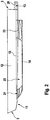
- FIGS. 1 and 2 show an underwater hull 1 of a watercraft, not shown.
- the underwater hull 1 extends from a bow 2 to a stern 3.
- the underwater hull 1 has two parallel aligned float elements 10, which extend from the bow area 11, the same seen in the axial direction of the underwater hull 1 center 12 of the same aft.
- WLR The waterline is identified by reference 13 or WLR.
- WLR describes in the sense of the invention, the assumed waterline at rest during medium voyage of the ship.
- the total immersion depth is designated by the reference numeral 14.
- the bottom plate or the flat bottom 4 extends from the bow portion 11 to the rear 3.
- the bottom plate 4 seen in side view is curved, quasi executed in a flat S-arc, with several, preferably three inflection points P2 to P4 and thus several , preferably two immersion depth regions 5 and 6 are provided.
- the immersion depth 14 of the main hull 1 is therefore advantageously divided into two immersion depth regions 5 and 6, and is defined by the definition of five points P1 to P5 or inflection points P2 to P4, by which the contour of the main hull 1 is interpolated.
- five turning points P1 to P5 four distances A1 to A4 are defined in their axial length, which represent the construction length of the bottom plate 4, which is guided by the bow 2 just above the waterline 13 in multiple arcs to the maximum depth 14 of the skin rump 1.
- the location of the five points P1 to P5 is designated by the distances A1 to A4 on the central axis of the ship and in the height to the waterline 13 of the resting ship.
- the route A1 extends from the starting point P1 to the point P2, the route A2 connecting from point P2 to point P3.
- the distance A3 following the route A2 extends from the point P3 to the point P4, followed by the route A4 ending at the point P5 or at the end point P5.
- WLR describes in the sense of the invention, the assumed waterline 13 at rest during medium voyage of the ship.
- the assumed waterline 13 in the resting state is determined by the total weight of the ship, which would have to be carried by the main hull 1 in flat bottom plate 4 only.
- a second point P2 or inflection point P2 which is arranged between the starting point P1 and a third point P3 or inflection point P3, is at a height variable auxiliary point.
- On the longitudinal axis of this P2 is about 9% of the construction length of the bottom plate 4 behind (so seen in the direction of the rear 3) the starting point P1.
- the third inflection point P3 is an essential construction point, which lies in its longitudinal distance 1/6 of the construction length of the bottom plate 4 behind the starting point P1.
- the altitude or depth is preferably about 40% of the total immersion depth 14 of the main hull. 1
- a fourth point P4 or inflection point P4 is the design point which is% before the end of the design length of the bottom plate 4 on the main axis. It lies in its height at the depth of the diving depth of the main hull 1 determined as described above. Thus, the second diving depth or the second diving depth area 6 is described in the third distance A3.
- the contour of the bottom plate 4 forms in the interpolation from the third point P3 a right arc, which soon changes to a left arc to get to the fourth point P4. Due to the slight change in the altitude of the starting point P1 and the second point P2 or inflection point P2 of naturally occurring inflection point 7 is set by the right arc in a left arc within the third distance A3 so that the naturally occurring inflection point 7 is located in front of the center of gravity of the hull. Only in this way is it possible that the resulting hydrodynamic effect with increasing travel of the watercraft can lift the bow area 11 out of the water, in order to reduce the wetted surface of the main hull 1 as the journey progresses.
- An end point P5 is at the same height as the fourth point P4 or inflection point P4 at the end of the bottom plate 4.
- the float elements extend parallel to the longitudinal central axis of the vessel or of the underwater vessel.
- two float elements are provided, which are equally spaced on both sides of the central longitudinal axis to this and identical executed.
- the float elements 10 have a bow region 21, a central region 22 and a rear region 23. Overall, the float elements 10 have a length, which corresponds to 70% of the total length of the underwater hull 1.
- the bow region 21 has an axial length of about 20% of the float element length, with the tail region 23 having a length amount of about 25% of the float element length.
- the rear region 23 is therefore designed with respect to the total swimmer length with a greater length than the bow region 21.
- the central region 22 would have expediently Axiallyn amount of about 55% of the float element length.
- the bow region 21 of the respective float element 10 is designed to be pointed at the bow end and widens to form a body 24 which is cylindrical in plan view and on which the middle region 22 adjoins.
- the middle region 22 is continued with the cylindrically executed body 24 in the direction of the rear region 23.
- the rear region 23 initially continues the cylindrical body 24 seen in plan view, and then tapers to a point, so that an end tip 25 is oriented towards the stern of the underwater hull 1.
- the float elements 10 have with their respective central longitudinal axis X seen in the transverse direction at a distance 26 to each other, which corresponds to an amount of about 65% of the width 27 of the underwater hull 1.
- the float elements 10 are exemplified so that a water flow guide to the drive screw is present, the water flow velocity is advantageously reduced below the underwater hull 1 and between the float elements 10 by the slimming in the rear portion 23 of the float element.
- the float elements 10 are spaced as far as possible from the central longitudinal axis X but not at a maximum distance from it and thus are not arranged directly on the side edges 28 of the underwater hull 1.
- FIG. 4 It can be seen that the float elements 10, which are cylindrical in plan view, are essentially rectangular, water flow guiding devices still being recognizable. In the figures, eg in FIG. 3 is still an outboard platform 29 recognizable.
Landscapes
- Physics & Mathematics (AREA)
- Fluid Mechanics (AREA)
- Chemical & Material Sciences (AREA)
- Engineering & Computer Science (AREA)
- Combustion & Propulsion (AREA)
- Mechanical Engineering (AREA)
- Ocean & Marine Engineering (AREA)
- Other Liquid Machine Or Engine Such As Wave Power Use (AREA)
Claims (10)
- Bateau, lequel présente une carène (1) avec une plaque de fond (4), laquelle carène s'étend d'une proue (2) à une poupe (3), dans lequel la carène (1) présente en section longitudinale un tracé curviligne depuis la proue (2) en direction de la poupe (3) tel, que la carène (1) présente plusieurs zones de tirant d'eau (5, 6) se mélangeant respectivement, dans lequel le tirant d'eau maximal (14) à l'arrière est atteint à une distance de près de 25 % de la ligne de flottaison totale (13) par rapport à la poupe (3), dans lequel la carène (1) présente deux zones de tirant d'eau (5, 6) et cinq points d'inflexion (P1 à P5), et la carène (1) présentant deux éléments flotteurs (10) orientés parallèlement l'un par rapport à l'autre, lesquels s'étendent à partir de la zone de la proue, en enjambant le centre (12) de cette même lorsque vu en direction axiale de la carène, vers l'arrière,
caractérisé en ce
qu'un quatrième point (P4) ou point d'inflexion (P4) se trouve à ¼ avant la fin de la longueur de construction de la plaque de fond (4) sur l'axe médian longitudinal et est disposé dans sa hauteur à la profondeur du tirant d'eau de la carène principale (1), dans lequel la deuxième zone de tirant d'eau (6) est disposée dans la troisième étendue (A3), dans lequel le tracé du contour de la plaque de fond (4) forme, lors de l'interpolation à partir du troisième point (P3), un virage à droite et ainsi une concavité, lequel virage se transforme aussitôt en un virage à gauche et ainsi en une convexité, pour parvenir au quatrième point (P4), dans lequel, grâce au léger changement de la position en hauteur du point de départ (P1) et du deuxième point (P2) ou point d'inflexion (P2), un point d'inflexion (7) se formant naturellement du virage à droite en un virage à gauche à l'intérieur de la troisième étendue (A3) est réglé d'une façon telle, que le point d'inflexion (7) se formant naturellement se situe avant le centre de gravité. - Bateau selon la revendication 1, caractérisé en ce que la carène (1) s'étend au moins partiellement selon un arc en S plat.
- Bateau selon la revendication 1 ou 2, caractérisé en ce qu'une première zone de tirant d'eau (5) s'étend à partir de la proue (2) en courant de manière bombée jusqu'à un taux de tirant d'eau de près de 40 % du tirant d'eau total (14) de la carène (1).
- Bateau selon l'une des revendications précédentes, caractérisé en ce qu'au niveau d'un premier point d'inflexion (P1) en tant que point de départ (P1) de la plaque de fond (4), à peu près ½ du tirant d'eau total (14) de la carène principale (1) se situe au-dessus de la ligne de flottaison (13).
- Bateau selon l'une des revendications précédentes, caractérisé en ce qu'un deuxième point (P2) ou point d'inflexion (P2) disposé entre le point de départ (P1) et un troisième point (P3) ou point d'inflexion (P3), se situe sur l'axe longitudinal à peu près de l'ordre de 9 % de la longueur de construction de la plaque de fond (4) derrière le point de départ (P1).
- Bateau selon l'une des revendications précédentes, caractérisé en ce que le troisième point d'inflexion (P3) se situe à une distance en longueur de l'ordre de 1/6 de la longueur de construction de la plaque de fond (4) derrière le point de départ (P1), dans lequel la position en hauteur ou profondeur est de préférence environ de l'ordre de 40 % du tirant d'eau total (14) de la carène principale (1).
- Bateau selon l'une des revendications précédentes, caractérisé en ce que les éléments flotteurs (10) sont réalisés parallèlement à l'axe médian longitudinal de la carène (1) et sont réalisés avec un même espacement par rapport à l'axe médian longitudinal, des deux côtés de celui-ci, et de façon identique.
- Bateau selon l'une des revendications précédentes, caractérisé en ce que les éléments flotteurs (10) présentent une zone de proue (21), une zone du milieu (22) et une zone de poupe (23) et présentent une valeur de longueur qui correspond à 70 % de la longueur totale de la carène (1).
- Bateau selon l'une des revendications précédentes, caractérisé en ce que l'élément flotteur (10) respectif présente, au niveau de sa zone de proue (21), une valeur de longueur axiale de près de 20 % de la longueur de l'élément flotteur, dans lequel la zone de proue (23) de celui-ci présente une valeur de longueur de près de 25 % de la longueur de l'élément flotteur.
- Bateau selon l'une des revendications précédentes, caractérisé en ce qu'une zone de proue (21) de l'élément flotteur (10) respectif est réalisée de manière pointue côté proue et s'élargie en un corps (24), réalisé de façon cylindrique lorsque vu de dessus, avec lequel une zone du milieu (22) est en jonction, dans lequel la zone du milieu (22) se poursuit en direction de la zone de poupe (23) avec le corps (24) cylindrique lorsque vu de dessus, dans lequel la zone de poupe (23) assure tout d'abord la poursuite du corps cylindrique (24) lorsque vu de dessus et se rétréci ensuite en pointe de manière à ce qu'une pointe d'extrémité (25) soit orientée vers la poupe de la carène (1).
Applications Claiming Priority (2)
| Application Number | Priority Date | Filing Date | Title |
|---|---|---|---|
| DE202012006183U DE202012006183U1 (de) | 2012-06-27 | 2012-06-27 | Unterwasserrumpf eines Wasserfahrzeuges |
| PCT/DE2013/000323 WO2014000723A1 (fr) | 2012-06-27 | 2013-06-17 | Carène de bateau |
Publications (2)
| Publication Number | Publication Date |
|---|---|
| EP2867111A1 EP2867111A1 (fr) | 2015-05-06 |
| EP2867111B1 true EP2867111B1 (fr) | 2017-03-29 |
Family
ID=46671752
Family Applications (1)
| Application Number | Title | Priority Date | Filing Date |
|---|---|---|---|
| EP13741659.0A Not-in-force EP2867111B1 (fr) | 2012-06-27 | 2013-06-17 | Carène de bateau |
Country Status (3)
| Country | Link |
|---|---|
| EP (1) | EP2867111B1 (fr) |
| DE (2) | DE202012006183U1 (fr) |
| WO (1) | WO2014000723A1 (fr) |
Family Cites Families (4)
| Publication number | Priority date | Publication date | Assignee | Title |
|---|---|---|---|---|
| US5265554A (en) * | 1992-06-23 | 1993-11-30 | Meredith Marine, Inc. | Boat construction |
| US7578250B2 (en) * | 2005-01-03 | 2009-08-25 | Baker Elbert H | Watercraft with wave deflecting hull |
| FR2890040B1 (fr) * | 2005-08-26 | 2007-10-05 | Dcn Sa | Coque de navire comportant au moins un flotteur |
| GB2481581B (en) * | 2010-06-28 | 2016-07-13 | Pet Mate Ltd | Boat hulls |
-
2012
- 2012-06-27 DE DE202012006183U patent/DE202012006183U1/de not_active Expired - Lifetime
-
2013
- 2013-06-17 EP EP13741659.0A patent/EP2867111B1/fr not_active Not-in-force
- 2013-06-17 DE DE112013003460.3T patent/DE112013003460A5/de not_active Withdrawn
- 2013-06-17 WO PCT/DE2013/000323 patent/WO2014000723A1/fr not_active Ceased
Non-Patent Citations (1)
| Title |
|---|
| None * |
Also Published As
| Publication number | Publication date |
|---|---|
| WO2014000723A1 (fr) | 2014-01-03 |
| DE112013003460A5 (de) | 2015-03-26 |
| DE202012006183U1 (de) | 2012-07-16 |
| EP2867111A1 (fr) | 2015-05-06 |
Similar Documents
| Publication | Publication Date | Title |
|---|---|---|
| DE69612995T2 (de) | Einzelrumpfwasserfahrzeug | |
| DE69802283T2 (de) | Schnelles einrumpfschiff mit heckstabilisatoren | |
| EP0358888B1 (fr) | Voilier | |
| EP0182314A2 (fr) | Véhicule à coussin d'air du type catamaran | |
| EP0094673A2 (fr) | Arrangement des ailes portantes pour catamaran | |
| DE69605432T2 (de) | Wasserfahrzeuge | |
| DE202010015531U1 (de) | Wasserfahrzeug | |
| CH718114A2 (de) | Wasserfahrzeug. | |
| EP1177129B1 (fr) | Bateau rapide allant en mer et a stabilite de route, a coque optimisee pour une helice de gouvernail | |
| WO1994018063A1 (fr) | Coque de bateau, notamment pour voiliers et planches a voile | |
| EP0149855A2 (fr) | Coque pour engins flottants | |
| EP2867111B1 (fr) | Carène de bateau | |
| DE19837888C1 (de) | Schiffsrumpf | |
| DE102015009440A1 (de) | Antriebs-Stabilisatoren, um Schiffe zu stabilisieren | |
| DE3801317C2 (fr) | ||
| WO2022118185A2 (fr) | Véhicule marin | |
| DE29908430U1 (de) | Schnelles seegehendes Schiff | |
| EP2769909A2 (fr) | Carène et coque de bateau ainsi que bateau doté d'une coque | |
| DE10134778B4 (de) | Segelboot mit stark eingezogenen Wasserlinien | |
| DE102011010962B3 (de) | Segelboot | |
| DE10240534B4 (de) | Schiff | |
| DE3122863A1 (de) | "segelboot" | |
| AT504311B1 (de) | Bootskörper für schnelle wasserfahrzeuge | |
| DE1506204C (de) | Gleitboot mit deltafbrmiger Gleitfläche | |
| DE102009056834A1 (de) | Wasserfahrzeug mit Unterwasserschwimmkörper und Überwassersteuerstand |
Legal Events
| Date | Code | Title | Description |
|---|---|---|---|
| PUAI | Public reference made under article 153(3) epc to a published international application that has entered the european phase |
Free format text: ORIGINAL CODE: 0009012 |
|
| 17P | Request for examination filed |
Effective date: 20150108 |
|
| AK | Designated contracting states |
Kind code of ref document: A1 Designated state(s): AL AT BE BG CH CY CZ DE DK EE ES FI FR GB GR HR HU IE IS IT LI LT LU LV MC MK MT NL NO PL PT RO RS SE SI SK SM TR |
|
| AX | Request for extension of the european patent |
Extension state: BA ME |
|
| DAX | Request for extension of the european patent (deleted) | ||
| RIC1 | Information provided on ipc code assigned before grant |
Ipc: B63B 1/20 20060101ALI20161020BHEP Ipc: B63B 1/04 20060101AFI20161020BHEP |
|
| GRAP | Despatch of communication of intention to grant a patent |
Free format text: ORIGINAL CODE: EPIDOSNIGR1 |
|
| STAA | Information on the status of an ep patent application or granted ep patent |
Free format text: STATUS: GRANT OF PATENT IS INTENDED |
|
| INTG | Intention to grant announced |
Effective date: 20161220 |
|
| GRAS | Grant fee paid |
Free format text: ORIGINAL CODE: EPIDOSNIGR3 |
|
| GRAA | (expected) grant |
Free format text: ORIGINAL CODE: 0009210 |
|
| STAA | Information on the status of an ep patent application or granted ep patent |
Free format text: STATUS: THE PATENT HAS BEEN GRANTED |
|
| AK | Designated contracting states |
Kind code of ref document: B1 Designated state(s): AL AT BE BG CH CY CZ DE DK EE ES FI FR GB GR HR HU IE IS IT LI LT LU LV MC MK MT NL NO PL PT RO RS SE SI SK SM TR |
|
| REG | Reference to a national code |
Ref country code: GB Ref legal event code: FG4D Free format text: NOT ENGLISH |
|
| REG | Reference to a national code |
Ref country code: CH Ref legal event code: EP |
|
| REG | Reference to a national code |
Ref country code: AT Ref legal event code: REF Ref document number: 879473 Country of ref document: AT Kind code of ref document: T Effective date: 20170415 |
|
| REG | Reference to a national code |
Ref country code: IE Ref legal event code: FG4D Free format text: LANGUAGE OF EP DOCUMENT: GERMAN |
|
| REG | Reference to a national code |
Ref country code: DE Ref legal event code: R096 Ref document number: 502013006811 Country of ref document: DE |
|
| REG | Reference to a national code |
Ref country code: NL Ref legal event code: FP Ref country code: FR Ref legal event code: PLFP Year of fee payment: 5 |
|
| PG25 | Lapsed in a contracting state [announced via postgrant information from national office to epo] |
Ref country code: FI Free format text: LAPSE BECAUSE OF FAILURE TO SUBMIT A TRANSLATION OF THE DESCRIPTION OR TO PAY THE FEE WITHIN THE PRESCRIBED TIME-LIMIT Effective date: 20170329 Ref country code: LT Free format text: LAPSE BECAUSE OF FAILURE TO SUBMIT A TRANSLATION OF THE DESCRIPTION OR TO PAY THE FEE WITHIN THE PRESCRIBED TIME-LIMIT Effective date: 20170329 Ref country code: GR Free format text: LAPSE BECAUSE OF FAILURE TO SUBMIT A TRANSLATION OF THE DESCRIPTION OR TO PAY THE FEE WITHIN THE PRESCRIBED TIME-LIMIT Effective date: 20170630 Ref country code: HR Free format text: LAPSE BECAUSE OF FAILURE TO SUBMIT A TRANSLATION OF THE DESCRIPTION OR TO PAY THE FEE WITHIN THE PRESCRIBED TIME-LIMIT Effective date: 20170329 Ref country code: NO Free format text: LAPSE BECAUSE OF FAILURE TO SUBMIT A TRANSLATION OF THE DESCRIPTION OR TO PAY THE FEE WITHIN THE PRESCRIBED TIME-LIMIT Effective date: 20170629 |
|
| PG25 | Lapsed in a contracting state [announced via postgrant information from national office to epo] |
Ref country code: BG Free format text: LAPSE BECAUSE OF FAILURE TO SUBMIT A TRANSLATION OF THE DESCRIPTION OR TO PAY THE FEE WITHIN THE PRESCRIBED TIME-LIMIT Effective date: 20170629 Ref country code: SE Free format text: LAPSE BECAUSE OF FAILURE TO SUBMIT A TRANSLATION OF THE DESCRIPTION OR TO PAY THE FEE WITHIN THE PRESCRIBED TIME-LIMIT Effective date: 20170329 Ref country code: LV Free format text: LAPSE BECAUSE OF FAILURE TO SUBMIT A TRANSLATION OF THE DESCRIPTION OR TO PAY THE FEE WITHIN THE PRESCRIBED TIME-LIMIT Effective date: 20170329 Ref country code: RS Free format text: LAPSE BECAUSE OF FAILURE TO SUBMIT A TRANSLATION OF THE DESCRIPTION OR TO PAY THE FEE WITHIN THE PRESCRIBED TIME-LIMIT Effective date: 20170329 |
|
| PG25 | Lapsed in a contracting state [announced via postgrant information from national office to epo] |
Ref country code: CZ Free format text: LAPSE BECAUSE OF FAILURE TO SUBMIT A TRANSLATION OF THE DESCRIPTION OR TO PAY THE FEE WITHIN THE PRESCRIBED TIME-LIMIT Effective date: 20170329 Ref country code: EE Free format text: LAPSE BECAUSE OF FAILURE TO SUBMIT A TRANSLATION OF THE DESCRIPTION OR TO PAY THE FEE WITHIN THE PRESCRIBED TIME-LIMIT Effective date: 20170329 Ref country code: ES Free format text: LAPSE BECAUSE OF FAILURE TO SUBMIT A TRANSLATION OF THE DESCRIPTION OR TO PAY THE FEE WITHIN THE PRESCRIBED TIME-LIMIT Effective date: 20170329 Ref country code: SK Free format text: LAPSE BECAUSE OF FAILURE TO SUBMIT A TRANSLATION OF THE DESCRIPTION OR TO PAY THE FEE WITHIN THE PRESCRIBED TIME-LIMIT Effective date: 20170329 Ref country code: IT Free format text: LAPSE BECAUSE OF FAILURE TO SUBMIT A TRANSLATION OF THE DESCRIPTION OR TO PAY THE FEE WITHIN THE PRESCRIBED TIME-LIMIT Effective date: 20170329 Ref country code: RO Free format text: LAPSE BECAUSE OF FAILURE TO SUBMIT A TRANSLATION OF THE DESCRIPTION OR TO PAY THE FEE WITHIN THE PRESCRIBED TIME-LIMIT Effective date: 20170329 |
|
| PG25 | Lapsed in a contracting state [announced via postgrant information from national office to epo] |
Ref country code: SM Free format text: LAPSE BECAUSE OF FAILURE TO SUBMIT A TRANSLATION OF THE DESCRIPTION OR TO PAY THE FEE WITHIN THE PRESCRIBED TIME-LIMIT Effective date: 20170329 Ref country code: PL Free format text: LAPSE BECAUSE OF FAILURE TO SUBMIT A TRANSLATION OF THE DESCRIPTION OR TO PAY THE FEE WITHIN THE PRESCRIBED TIME-LIMIT Effective date: 20170329 Ref country code: IS Free format text: LAPSE BECAUSE OF FAILURE TO SUBMIT A TRANSLATION OF THE DESCRIPTION OR TO PAY THE FEE WITHIN THE PRESCRIBED TIME-LIMIT Effective date: 20170729 Ref country code: PT Free format text: LAPSE BECAUSE OF FAILURE TO SUBMIT A TRANSLATION OF THE DESCRIPTION OR TO PAY THE FEE WITHIN THE PRESCRIBED TIME-LIMIT Effective date: 20170731 |
|
| REG | Reference to a national code |
Ref country code: DE Ref legal event code: R097 Ref document number: 502013006811 Country of ref document: DE |
|
| PG25 | Lapsed in a contracting state [announced via postgrant information from national office to epo] |
Ref country code: MC Free format text: LAPSE BECAUSE OF FAILURE TO SUBMIT A TRANSLATION OF THE DESCRIPTION OR TO PAY THE FEE WITHIN THE PRESCRIBED TIME-LIMIT Effective date: 20170329 Ref country code: DK Free format text: LAPSE BECAUSE OF FAILURE TO SUBMIT A TRANSLATION OF THE DESCRIPTION OR TO PAY THE FEE WITHIN THE PRESCRIBED TIME-LIMIT Effective date: 20170329 |
|
| REG | Reference to a national code |
Ref country code: CH Ref legal event code: PL |
|
| PLBE | No opposition filed within time limit |
Free format text: ORIGINAL CODE: 0009261 |
|
| STAA | Information on the status of an ep patent application or granted ep patent |
Free format text: STATUS: NO OPPOSITION FILED WITHIN TIME LIMIT |
|
| 26N | No opposition filed |
Effective date: 20180103 |
|
| REG | Reference to a national code |
Ref country code: IE Ref legal event code: MM4A |
|
| PG25 | Lapsed in a contracting state [announced via postgrant information from national office to epo] |
Ref country code: LU Free format text: LAPSE BECAUSE OF NON-PAYMENT OF DUE FEES Effective date: 20170617 Ref country code: LI Free format text: LAPSE BECAUSE OF NON-PAYMENT OF DUE FEES Effective date: 20170630 Ref country code: CH Free format text: LAPSE BECAUSE OF NON-PAYMENT OF DUE FEES Effective date: 20170630 Ref country code: IE Free format text: LAPSE BECAUSE OF NON-PAYMENT OF DUE FEES Effective date: 20170617 |
|
| PG25 | Lapsed in a contracting state [announced via postgrant information from national office to epo] |
Ref country code: SI Free format text: LAPSE BECAUSE OF FAILURE TO SUBMIT A TRANSLATION OF THE DESCRIPTION OR TO PAY THE FEE WITHIN THE PRESCRIBED TIME-LIMIT Effective date: 20170329 |
|
| REG | Reference to a national code |
Ref country code: FR Ref legal event code: PLFP Year of fee payment: 6 |
|
| PG25 | Lapsed in a contracting state [announced via postgrant information from national office to epo] |
Ref country code: MT Free format text: LAPSE BECAUSE OF FAILURE TO SUBMIT A TRANSLATION OF THE DESCRIPTION OR TO PAY THE FEE WITHIN THE PRESCRIBED TIME-LIMIT Effective date: 20170329 |
|
| PG25 | Lapsed in a contracting state [announced via postgrant information from national office to epo] |
Ref country code: HU Free format text: LAPSE BECAUSE OF FAILURE TO SUBMIT A TRANSLATION OF THE DESCRIPTION OR TO PAY THE FEE WITHIN THE PRESCRIBED TIME-LIMIT; INVALID AB INITIO Effective date: 20130617 |
|
| REG | Reference to a national code |
Ref country code: AT Ref legal event code: MM01 Ref document number: 879473 Country of ref document: AT Kind code of ref document: T Effective date: 20180617 |
|
| PG25 | Lapsed in a contracting state [announced via postgrant information from national office to epo] |
Ref country code: CY Free format text: LAPSE BECAUSE OF FAILURE TO SUBMIT A TRANSLATION OF THE DESCRIPTION OR TO PAY THE FEE WITHIN THE PRESCRIBED TIME-LIMIT Effective date: 20170329 |
|
| PG25 | Lapsed in a contracting state [announced via postgrant information from national office to epo] |
Ref country code: MK Free format text: LAPSE BECAUSE OF FAILURE TO SUBMIT A TRANSLATION OF THE DESCRIPTION OR TO PAY THE FEE WITHIN THE PRESCRIBED TIME-LIMIT Effective date: 20170329 |
|
| PG25 | Lapsed in a contracting state [announced via postgrant information from national office to epo] |
Ref country code: AT Free format text: LAPSE BECAUSE OF NON-PAYMENT OF DUE FEES Effective date: 20180617 |
|
| PG25 | Lapsed in a contracting state [announced via postgrant information from national office to epo] |
Ref country code: TR Free format text: LAPSE BECAUSE OF FAILURE TO SUBMIT A TRANSLATION OF THE DESCRIPTION OR TO PAY THE FEE WITHIN THE PRESCRIBED TIME-LIMIT Effective date: 20170329 |
|
| PG25 | Lapsed in a contracting state [announced via postgrant information from national office to epo] |
Ref country code: AL Free format text: LAPSE BECAUSE OF FAILURE TO SUBMIT A TRANSLATION OF THE DESCRIPTION OR TO PAY THE FEE WITHIN THE PRESCRIBED TIME-LIMIT Effective date: 20170329 |
|
| P01 | Opt-out of the competence of the unified patent court (upc) registered |
Effective date: 20230819 |
|
| PGFP | Annual fee paid to national office [announced via postgrant information from national office to epo] |
Ref country code: DE Payment date: 20240627 Year of fee payment: 12 |
|
| PGFP | Annual fee paid to national office [announced via postgrant information from national office to epo] |
Ref country code: NL Payment date: 20240627 Year of fee payment: 12 |
|
| PGFP | Annual fee paid to national office [announced via postgrant information from national office to epo] |
Ref country code: FR Payment date: 20240627 Year of fee payment: 12 |
|
| PGFP | Annual fee paid to national office [announced via postgrant information from national office to epo] |
Ref country code: BE Payment date: 20240627 Year of fee payment: 12 |
|
| PGFP | Annual fee paid to national office [announced via postgrant information from national office to epo] |
Ref country code: GB Payment date: 20240723 Year of fee payment: 12 |
|
| REG | Reference to a national code |
Ref country code: DE Ref legal event code: R119 Ref document number: 502013006811 Country of ref document: DE |
|
| REG | Reference to a national code |
Ref country code: NL Ref legal event code: MM Effective date: 20250701 |
|
| GBPC | Gb: european patent ceased through non-payment of renewal fee |
Effective date: 20250617 |
|
| REG | Reference to a national code |
Ref country code: BE Ref legal event code: MM Effective date: 20250630 |
|
| PG25 | Lapsed in a contracting state [announced via postgrant information from national office to epo] |
Ref country code: NL Free format text: LAPSE BECAUSE OF NON-PAYMENT OF DUE FEES Effective date: 20250701 |
|
| PG25 | Lapsed in a contracting state [announced via postgrant information from national office to epo] |
Ref country code: GB Free format text: LAPSE BECAUSE OF NON-PAYMENT OF DUE FEES Effective date: 20250617 |
|
| PG25 | Lapsed in a contracting state [announced via postgrant information from national office to epo] |
Ref country code: DE Free format text: LAPSE BECAUSE OF NON-PAYMENT OF DUE FEES Effective date: 20260101 |
|
| PG25 | Lapsed in a contracting state [announced via postgrant information from national office to epo] |
Ref country code: BE Free format text: LAPSE BECAUSE OF NON-PAYMENT OF DUE FEES Effective date: 20250630 |
|
| PG25 | Lapsed in a contracting state [announced via postgrant information from national office to epo] |
Ref country code: FR Free format text: LAPSE BECAUSE OF NON-PAYMENT OF DUE FEES Effective date: 20250630 |