EP2867575B1 - Beleuchtungsvorrichtung - Google Patents
Beleuchtungsvorrichtung Download PDFInfo
- Publication number
- EP2867575B1 EP2867575B1 EP13729030.0A EP13729030A EP2867575B1 EP 2867575 B1 EP2867575 B1 EP 2867575B1 EP 13729030 A EP13729030 A EP 13729030A EP 2867575 B1 EP2867575 B1 EP 2867575B1
- Authority
- EP
- European Patent Office
- Prior art keywords
- illuminating device
- lens
- circuit board
- heat sink
- spring
- Prior art date
- Legal status (The legal status is an assumption and is not a legal conclusion. Google has not performed a legal analysis and makes no representation as to the accuracy of the status listed.)
- Active
Links
Images

Classifications
-
- F—MECHANICAL ENGINEERING; LIGHTING; HEATING; WEAPONS; BLASTING
- F21—LIGHTING
- F21V—FUNCTIONAL FEATURES OR DETAILS OF LIGHTING DEVICES OR SYSTEMS THEREOF; STRUCTURAL COMBINATIONS OF LIGHTING DEVICES WITH OTHER ARTICLES, NOT OTHERWISE PROVIDED FOR
- F21V19/00—Fastening of light sources or lamp holders
- F21V19/001—Fastening of light sources or lamp holders the light sources being semiconductors devices, e.g. LEDs
- F21V19/003—Fastening of light source holders, e.g. of circuit boards or substrates holding light sources
- F21V19/0035—Fastening of light source holders, e.g. of circuit boards or substrates holding light sources the fastening means being capable of simultaneously attaching of an other part, e.g. a housing portion or an optical component
-
- F—MECHANICAL ENGINEERING; LIGHTING; HEATING; WEAPONS; BLASTING
- F21—LIGHTING
- F21K—NON-ELECTRIC LIGHT SOURCES USING LUMINESCENCE; LIGHT SOURCES USING ELECTROCHEMILUMINESCENCE; LIGHT SOURCES USING CHARGES OF COMBUSTIBLE MATERIAL; LIGHT SOURCES USING SEMICONDUCTOR DEVICES AS LIGHT-GENERATING ELEMENTS; LIGHT SOURCES NOT OTHERWISE PROVIDED FOR
- F21K9/00—Light sources using semiconductor devices as light-generating elements, e.g. using light-emitting diodes [LED] or lasers
- F21K9/20—Light sources comprising attachment means
- F21K9/23—Retrofit light sources for lighting devices with a single fitting for each light source, e.g. for substitution of incandescent lamps with bayonet or threaded fittings
-
- F—MECHANICAL ENGINEERING; LIGHTING; HEATING; WEAPONS; BLASTING
- F21—LIGHTING
- F21V—FUNCTIONAL FEATURES OR DETAILS OF LIGHTING DEVICES OR SYSTEMS THEREOF; STRUCTURAL COMBINATIONS OF LIGHTING DEVICES WITH OTHER ARTICLES, NOT OTHERWISE PROVIDED FOR
- F21V17/00—Fastening of component parts of lighting devices, e.g. shades, globes, refractors, reflectors, filters, screens, grids or protective cages
- F21V17/10—Fastening of component parts of lighting devices, e.g. shades, globes, refractors, reflectors, filters, screens, grids or protective cages characterised by specific fastening means or way of fastening
- F21V17/16—Fastening of component parts of lighting devices, e.g. shades, globes, refractors, reflectors, filters, screens, grids or protective cages characterised by specific fastening means or way of fastening by deformation of parts; Snap action mounting
- F21V17/164—Fastening of component parts of lighting devices, e.g. shades, globes, refractors, reflectors, filters, screens, grids or protective cages characterised by specific fastening means or way of fastening by deformation of parts; Snap action mounting the parts being subjected to bending, e.g. snap joints
-
- F—MECHANICAL ENGINEERING; LIGHTING; HEATING; WEAPONS; BLASTING
- F21—LIGHTING
- F21V—FUNCTIONAL FEATURES OR DETAILS OF LIGHTING DEVICES OR SYSTEMS THEREOF; STRUCTURAL COMBINATIONS OF LIGHTING DEVICES WITH OTHER ARTICLES, NOT OTHERWISE PROVIDED FOR
- F21V19/00—Fastening of light sources or lamp holders
- F21V19/001—Fastening of light sources or lamp holders the light sources being semiconductors devices, e.g. LEDs
- F21V19/003—Fastening of light source holders, e.g. of circuit boards or substrates holding light sources
- F21V19/004—Fastening of light source holders, e.g. of circuit boards or substrates holding light sources by deformation of parts or snap action mountings, e.g. using clips
-
- F—MECHANICAL ENGINEERING; LIGHTING; HEATING; WEAPONS; BLASTING
- F21—LIGHTING
- F21V—FUNCTIONAL FEATURES OR DETAILS OF LIGHTING DEVICES OR SYSTEMS THEREOF; STRUCTURAL COMBINATIONS OF LIGHTING DEVICES WITH OTHER ARTICLES, NOT OTHERWISE PROVIDED FOR
- F21V5/00—Refractors for light sources
- F21V5/04—Refractors for light sources of lens shape
-
- F—MECHANICAL ENGINEERING; LIGHTING; HEATING; WEAPONS; BLASTING
- F21—LIGHTING
- F21V—FUNCTIONAL FEATURES OR DETAILS OF LIGHTING DEVICES OR SYSTEMS THEREOF; STRUCTURAL COMBINATIONS OF LIGHTING DEVICES WITH OTHER ARTICLES, NOT OTHERWISE PROVIDED FOR
- F21V29/00—Protecting lighting devices from thermal damage; Cooling or heating arrangements specially adapted for lighting devices or systems
- F21V29/50—Cooling arrangements
- F21V29/70—Cooling arrangements characterised by passive heat-dissipating elements, e.g. heat-sinks
-
- F—MECHANICAL ENGINEERING; LIGHTING; HEATING; WEAPONS; BLASTING
- F21—LIGHTING
- F21Y—INDEXING SCHEME ASSOCIATED WITH SUBCLASSES F21K, F21L, F21S and F21V, RELATING TO THE FORM OR THE KIND OF THE LIGHT SOURCES OR OF THE COLOUR OF THE LIGHT EMITTED
- F21Y2115/00—Light-generating elements of semiconductor light sources
- F21Y2115/10—Light-emitting diodes [LED]
Definitions
- the present invention relates to an illuminating device.
- a LED retrofit lamp generally has a heat sink, a circuit board arranged in the heat sink and a lens arranged at the light emergent opening of the heat sink, wherein a LED chip is arranged on the circuit board, and the lens is capable of processing light rays of the LED chip, to fulfill different illuminating effects.
- a LED chip is arranged on the circuit board, and the lens is capable of processing light rays of the LED chip, to fulfill different illuminating effects.
- An earlier patent application FR2962783A1 discloses an illuminating device comprising a heat sink and a lens connected with the heat sink to provide a pressure to a circuit board placed on the heat sink.
- the present invention provides an illuminating device, which has a few components, low cost and is easy to be assembled. Furthermore, after a long running time of the illuminating device according to the present invention, each component of the illuminating device still has relative high connection reliability.
- the illuminating device comprises a heat sink having a bottom wall and a circumferential wall extending from the bottom wall, defining an accommodating cavity; a lens arranged at an opening of the accommodating cavity; and a circuit board having a light source and being arranged on the bottom wall, wherein the lens includes at least one snap-fit structure and at least one pressing portion, and the snap-fit structure snaps into the circumferential wall to fix the lens to the heat sink and the lens presses the circuit board against the bottom wall through the pressing portion.
- the lens can be directly snapped at the heat sink through the snap-fit structure, without additional mechanical structures, such as bolt and hold shield etc.
- the illuminating device further comprises a biasing device arranged between the lens and the circuit board, which is used to provide a bias force between the lens and the circuit board.
- the spring After mounting the lens on the heat sink, the spring is extruded and is in a forced state. After a long running time of the illuminating device, the lens or the heat sink might be deformed because of aging. However, the lens is supported on the heat sink in the form of a prestress. Thus, even if the components are deformed, the lens would also be reliably fixed on the heat sink without loosening.
- the biasing device includes at least one spring and at least one insulation washer, wherein one end of the spring bears against the lens, and the other end bears against the circuit board through the insulation washer.
- the insulation washer is insulated from the spring and the circuit board, which avoids short circuit of the circuit board.
- the lens comprises a baseplate and at least one micro-lens structure formed on the baseplate.
- the micro-lens structure is more suitable for matching with a light source.
- a micro-lens structure is individually equipped for each light source, which is advantageous for individually adjusting light rays of a light source.
- the present invention it is provided that there is no need to additionally arrange an individual component, when configuring the micro-lens structure as the pressing portion. It reduces to a large extent the structural complexity of the lens and decreases the production cost.
- the lens further includes at least one positioning column formed on the baseplate, and the positioning column is configured as the pressing portion. It is advantageous that at least one through hole for insertion of the positioning column is formed on the circuit board.
- the positioning column can help with accurate alignment of the lens and a light source on the circuit board. It has practical significance particularly for the situation that the illuminating device has a plurality of light sources and a plurality of micro-lens structures. Furthermore, instead of micro-lens structure, the positioning column is used as the pressing portion, which reduces to a large extent design difficulty of the micro-lens structure.
- the positioning column includes a first section capable of being inserted into the through hole and a second section, wherein a connecting part of the first section and the second section forms a stop step, which presses against the circuit board. In an assembled state of the illuminating device, said stop step reliably presses the circuit board against the heat sink.
- the spring is nested onto the pressing portion.
- the pressing portion is capable of being used as guiding element of the spring, so as to avoid undesired displacement of the spring.
- the spring is a spiral spring.
- the spring can also be a spring of another type, for example plate spring.
- the snap-fit structure is configured as elastic hook.
- a projection is formed on the circumferential wall, and the elastic hook engages with the projection.
- the snap-fit structure of such type has a simple structure and easy manufacture. During practical assembly process, it only needs to insert the lens into the opening of the accommodating cavity, while the elastic hook is easy to engage with the projection, wherein the operation is simple and the connection is very tight.
- the heat sink further includes at least one fin, which radially extends on outer side of the circumferential wall.
- the fin significantly increases contact area of the heat sink with air of the environment, which improves radiating property of the heat sink.
- an embedding groove is formed in the bottom wall, and the circuit board is arranged in the embedding groove in a form fitting manner.
- the circuit board is therefore firmly held in the embedding groove, which prevents undesired movement of the circuit board.
- the circuit board is a ceramic circuit board, which has good thermal conductivity.
- the circuit board can also be a circuit board of another type, metal core circuit board for instance.
- the light source is a LED light source, which has advantages of long service lift, high luminous efficiency and environmental protection.
- Fig. 1 shows a composed schematic diagram of the first example of the illuminating device 100 according to the present invention.
- the illuminating device 100 according to the present invention comprises: a heat sink 1 having a bottom wall 111 and a circumferential wall 112 extending from the bottom wall 111, defining an accommodating cavity 11; a lens 2 arranged at an opening of the accommodating cavity 11 in the assembled state of the illuminating device 100 (see Fig. 3 ); and a circuit board 3 having a light source, wherein the circuit board 3 is arranged on the bottom wall 111 in the assembled state of the illuminating device 100.
- the circuit board 3 is a ceramic circuit board, and it can also be a circuit board of another type, such as metal core circuit board etc.
- the light source arranged on the circuit board 3 is a LED light source 7.
- the heat sink 1 further includes at least one fin 12, which radially extends on outer side of the circumferential wall 112.
- an embedding groove 114 is formed in the bottom wall 111, and the circuit board 3 is arranged in the embedding groove 114 in a form fitting manner.
- a thermal interface material 6 is arranged between the circuit board 3 and the bottom surface of the embedding groove 114 (see Fig. 3 ).
- the lens 2 includes a baseplate 21 and a micro-lens structure 22 formed on the baseplate 21.
- the lens 2 includes a baseplate 21 and a micro-lens structure 22 formed on the baseplate 21.
- only one LED light source 7 is arranged on the circuit board 3.
- only one micro-lens structure 22 is formed on the baseplate 21, wherein the micro-lens structure 22 is configured as pressing portion, which presses against the circuit board 3 by means of its free end.
- the lens 2 further includes at least one elastic hook 24 configured as snap-fit structure.
- the elastic hook 24 snaps into a projection 113 formed on the circumferential wall 112 to fix the lens 2 to the heat sink 1 , and the micro-lens structure 22 presses the circuit board 3 against the bottom surface of the embedding groove 114.
- the illuminating device 100 further comprises a biasing device between the lens 2 and the circuit board 3, which is used to provide a bias force between the lens 2 and the circuit board 3.
- the biasing structure includes a spring 4 configured as spiral spring and an insulation washer 5.
- the spring 4 is nested onto the micro-lens structure 22, wherein one end of the spring 4 bears against the baseplate 21 of the lens 2, while the other end bears against the circuit board 3 through the insulation washer 5.
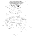
- Fig. 2 shows a composed schematic diagram of the second example of the illuminating device 100 according to the present invention.
- the heat sink 1 of the illuminating device 100 in the second example has the same structure as that of the illuminating device 100 in the first example, thus, it is not described here.
- the differences between the illuminating devices of the two examples lie in the amount of the LED light sources 7 on the circuit board 3 and the structure of the lens 2.
- a plurality of LED light sources 7 are arranged on the circuit board 3; in the present example, 4 LED light sources 7 are arranged.
- the structure of the lens 2 is correspondingly adjusted.
- 4 micro-lens structures 22 are formed on the baseplate 21 of the lens 2, viz. each LED light source 7 is equipped with one micro-lens structure 22.
- a plurality of positioning columns 23 are formed on the baseplate 21 of the lens 2, which are used as pressing portion.
- through holes 31 for insertion of the positioning columns are also formed on the circuit board 3.
- two positioning columns 23 are arranged and two through holes 31 are therefore opened on the circuit board 23.
- the positioning column 23 includes a first section 231 capable of being inserted into the through hole 31 and a second section 232, wherein a connecting part of the first section 231 and the second section 232 forms a stop step 233, which presses against the circuit board 3.
- the illuminating device 100 also has a biasing device arranged between the lens 2 and the circuit board 3.
- the biasing device includes tow springs 4, which are nested onto the positioning columns 23, instead of being nested onto the micro-lens structures 22.
- the biasing device in the second example fails to include an insulation washer 5.
- an insulation washer 5 can also be additionally arranged between the spring 4 and the circuit board 3.
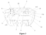
- Fig. 3 shows a sectional view of the illuminating device 100 in an assembled state in accordance with the first example as shown in Fig. 1 .
- the elastic hook 24 of the lens 2 engages with the projection 113 formed on the circumferential wall 112 of the accommodating cavity 11 of the heat sink 1, and the micro-lens structure 22 of the lens 2 presses the circuit board 3 against the bottom surface of the embedding groove 114.
- the spring 4 nested onto the micro-lens structure 22 is compressed between the baseplate 21 and the insulation washer 5 arranged on the circuit board 3, so that the spring 4 is in a forced state.
- the lens 2 or the heat sink 1 might be deformed because of aging.
- the lens 2 is supported on the heat sink 1 in the form of a prestress.
- the lens 2 would also be reliably fixed on the heat sink without loosening.
Landscapes
- Engineering & Computer Science (AREA)
- General Engineering & Computer Science (AREA)
- Physics & Mathematics (AREA)
- Microelectronics & Electronic Packaging (AREA)
- Optics & Photonics (AREA)
- Arrangement Of Elements, Cooling, Sealing, Or The Like Of Lighting Devices (AREA)
- Non-Portable Lighting Devices Or Systems Thereof (AREA)
- Fastening Of Light Sources Or Lamp Holders (AREA)
Claims (15)
- Beleuchtungsvorrichtung (100), umfassend: eine Wärmesenke (1), die eine Bodenwand (111) und eine von der Bodenwand (111) aus verlaufende umlaufende Wand (112) aufweist und einen Aufnahmehohlraum (11) definiert; eine Linse (2), die an einer Öffnung des Aufnahmehohlraums (11) angeordnet ist; und eine Leiterplatte (3), die eine Lichtquelle aufweist und an der Bodenwand (111) angeordnet ist, wobei die Linse (2) mindestens eine Rastkonstruktion und mindestens ein Pressteil enthält und die Rastkonstruktion in die umlaufende Wand einrastet, um die Linse (2) an der Wärmesenke (1) zu befestigen, und die Linse (2) die Leiterplatte (3) über das Pressteil gegen die Bodenwand drückt, gekennzeichnet dadurch, dass die Beleuchtungsvorrichtung (100) weiterhin eine zwischen der Linse (2) und der Leiterplatte (3) angeordnete Vorspannungsvorrichtung umfasst, die dazu dient, eine Vorspannkraft zwischen der Linse (2) und der Leiterplatte (3) bereitzustellen, und die Vorspannvorrichtung mindestens eine Feder (4) und mindestens eine Isolierscheibe (5) umfasst, wobei ein Ende der Feder (4) an der Linse (2) und das andere Ende über die Isolierscheibe (5) an der Leiterplatte (3) anliegt.
- Beleuchtungsvorrichtung (100) nach Anspruch 1, gekennzeichnet dadurch, dass die Linse (2) eine Grundplatte (21) und mindestens eine an der Grundplatte (21) ausgebildete Mikrolinsenstruktur (22) umfasst.
- Beleuchtungsvorrichtung (100) nach Anspruch 2, gekennzeichnet dadurch, dass die Mikrolinsenkonstruktion (22) als Pressteil konfiguriert ist.
- Beleuchtungsvorrichtung (100) nach Anspruch 2, gekennzeichnet dadurch, dass die Linse (2) weiterhin mindestens eine an der Grundplatte (21) ausgebildete Positioniersäule (23) umfasst, wobei die Positioniersäule (23) als Pressteil konfiguriert ist.
- Beleuchtungsvorrichtung (100) nach Anspruch 4, gekennzeichnet dadurch, dass an der Leiterplatte (3) mindestens eine Durchgangsbohrung (31) zum Einsetzen der Positioniersäule (23) ausgebildet ist.
- Beleuchtungsvorrichtung (100) nach Anspruch 5, gekennzeichnet dadurch, dass die Positioniersäule (23) einen ersten Abschnitt (231), der in eine Durchgangsbohrung (31) eingesetzt werden kann, und einen zweiten Abschnitt (232) umfasst, und ein Verbindungsteil des ersten Abschnitts (231) und des zweiten Abschnitts (232) eine Anschlagstufe (233) bildet, die gegen die Leiterplatte (3) drückt.
- Beleuchtungsvorrichtung (100) nach Anspruch 1, gekennzeichnet dadurch, dass die Feder (4) auf das Pressteil gesteckt ist.
- Beleuchtungsvorrichtung (100) nach Anspruch 1, gekennzeichnet dadurch, dass es sich bei der Feder (4) um eine Spiralfeder handelt.
- Beleuchtungsvorrichtung (100) nach einem der Ansprüche 1 bis 6, gekennzeichnet dadurch, dass die Rastkonstruktion als elastischer Haken (24) konfiguriert ist.
- Beleuchtungsvorrichtung (100) nach Anspruch 9, gekennzeichnet dadurch, dass ein Vorsprung (113) an der umlaufenden Wand (112) ausgebildet ist und der elastische Haken (24) in den Vorsprung (113) eingreift.
- Beleuchtungsvorrichtung (100) nach einem der Ansprüche 1 bis 6, gekennzeichnet dadurch, dass die Wärmesenke (1) weiterhin mindestens eine Rippe (12) umfasst, die radial an der Außenseite der umlaufenden Wand (112) verläuft.
- Beleuchtungsvorrichtung (100) nach einem der Ansprüche 1 bis 6, gekennzeichnet dadurch, dass eine Aufnahmenut (114) in der Bodenwand (111) ausgebildet ist und die Leiterplatte (3) formschlüssig in der Aufnahmenut (114) angeordnet ist.
- Beleuchtungsvorrichtung (100) nach Anspruch 12, gekennzeichnet dadurch, dass ein thermisches Schnittstellenmaterial (6) zwischen der Leiterplatte (3) und der Unterseite der Einpressnut (114) angeordnet ist.
- Beleuchtungsvorrichtung (100) nach einem der Ansprüche 1 bis 6, gekennzeichnet dadurch, dass es sich bei der Leiterplatte (3) um eine keramische Leiterplatte handelt.
- Beleuchtungsvorrichtung (100) nach einem der Ansprüche 1 bis 6, gekennzeichnet dadurch, dass es sich bei der Lichtquelle um eine LED-Lichtquelle (7) handelt.
Applications Claiming Priority (2)
| Application Number | Priority Date | Filing Date | Title |
|---|---|---|---|
| CN201210217834.9A CN103511867B (zh) | 2012-06-27 | 2012-06-27 | 照明装置 |
| PCT/EP2013/062443 WO2014001110A1 (en) | 2012-06-27 | 2013-06-14 | Illuminating device |
Publications (2)
| Publication Number | Publication Date |
|---|---|
| EP2867575A1 EP2867575A1 (de) | 2015-05-06 |
| EP2867575B1 true EP2867575B1 (de) | 2016-11-02 |
Family
ID=48626458
Family Applications (1)
| Application Number | Title | Priority Date | Filing Date |
|---|---|---|---|
| EP13729030.0A Active EP2867575B1 (de) | 2012-06-27 | 2013-06-14 | Beleuchtungsvorrichtung |
Country Status (3)
| Country | Link |
|---|---|
| EP (1) | EP2867575B1 (de) |
| CN (1) | CN103511867B (de) |
| WO (1) | WO2014001110A1 (de) |
Families Citing this family (8)
| Publication number | Priority date | Publication date | Assignee | Title |
|---|---|---|---|---|
| GB2522419B (en) * | 2014-01-22 | 2016-05-11 | Collingwood Lighting Ltd | Lighting unit |
| GB2523844B (en) * | 2014-03-08 | 2016-04-27 | Lighttherm Ltd | LED lamp with embedded circuitry |
| CN103883908B (zh) * | 2014-03-14 | 2016-05-25 | 浙江生辉照明有限公司 | 定向照明led灯 |
| DE102016203400A1 (de) * | 2016-03-02 | 2017-09-07 | Ledvance Gmbh | Lichtmodul |
| FR3056699B1 (fr) | 2016-09-26 | 2019-06-28 | Valeo Vision | Module lumineux et dispositif lumineux pour vehicule auto-mobile comportant un tel module lumineux |
| IT202000018289A1 (it) * | 2020-07-28 | 2022-01-28 | Elica Spa | Dispositivo di illuminazione in particolare per cappe di aspirazione |
| IT202000018280A1 (it) * | 2020-07-28 | 2022-01-28 | Elica Spa | Dispositivo di illuminazione in particolare per cappe di aspirazione |
| CN112393129A (zh) * | 2020-12-04 | 2021-02-23 | 横店集团得邦照明股份有限公司 | 一种多档调节色温的灯具及其实现方法 |
Family Cites Families (6)
| Publication number | Priority date | Publication date | Assignee | Title |
|---|---|---|---|---|
| JP5363462B2 (ja) * | 2007-05-07 | 2013-12-11 | コーニンクレッカ フィリップス エヌ ヴェ | 改良された熱放散及び製造容易性を持つ面照明のためのledベースの照明器具 |
| JP4447644B2 (ja) * | 2008-07-15 | 2010-04-07 | シーシーエス株式会社 | 光照射装置 |
| FR2962783B1 (fr) * | 2010-07-15 | 2014-11-14 | Cooper Technologies Co | Dispositif d'eclairage a dissipation thermique |
| CN101968599B (zh) * | 2010-10-09 | 2012-02-22 | 厦门华联电子有限公司 | 红外监控的辅助照明装置 |
| CN202040604U (zh) * | 2011-03-23 | 2011-11-16 | 东贝光电科技股份有限公司 | 照明灯 |
| CN202177011U (zh) * | 2011-08-10 | 2012-03-28 | 许水金 | 一种汽车激光迎宾灯 |
-
2012
- 2012-06-27 CN CN201210217834.9A patent/CN103511867B/zh active Active
-
2013
- 2013-06-14 EP EP13729030.0A patent/EP2867575B1/de active Active
- 2013-06-14 WO PCT/EP2013/062443 patent/WO2014001110A1/en not_active Ceased
Also Published As
| Publication number | Publication date |
|---|---|
| WO2014001110A1 (en) | 2014-01-03 |
| CN103511867A (zh) | 2014-01-15 |
| CN103511867B (zh) | 2018-08-28 |
| EP2867575A1 (de) | 2015-05-06 |
Similar Documents
| Publication | Publication Date | Title |
|---|---|---|
| EP2867575B1 (de) | Beleuchtungsvorrichtung | |
| US8500301B2 (en) | Illuminant device and manufacturing method of lamp holder | |
| EP2297516B1 (de) | Verfahren zur montage eines led-moduls an einem kühlkörper | |
| US20120201023A1 (en) | Light irradiating device | |
| CN205402277U (zh) | 发光二极管照明装置 | |
| EP2721343B1 (de) | Befestigungsvorrichtung und anordnungsstruktur | |
| CN102483200A (zh) | 光源装置 | |
| EP2898264B1 (de) | Beleuchtungsvorrichtung und herstellungsverfahren dafür | |
| JP2011228117A (ja) | 発光ユニットを交換可能な発光ダイオード(led)ランプ構造体 | |
| US11293632B2 (en) | Lamp and light source substrate thereof | |
| JP2012119230A (ja) | Ledランプおよびled照明装置 | |
| EP3273155B1 (de) | Glühlampengehäusebefestigungsstruktur | |
| US20140153277A1 (en) | Assembling structure for led lamp module | |
| CN108317409B (zh) | 灯具 | |
| CN205504596U (zh) | 灯装置及照明装置 | |
| CN204164996U (zh) | 灯装置及照明器具 | |
| CN204313013U (zh) | 灯及照明装置 | |
| TWI509196B (zh) | 燈具 | |
| CN108131575B (zh) | 灯具及其装配座 | |
| EP2738444B1 (de) | Montagestruktur für ein LED-Lampenmodul | |
| JP2012252895A (ja) | 電球形電灯及びその筐体 | |
| WO2017150040A1 (ja) | 照明器具及びその製造方法 | |
| CN103813633A (zh) | 电路板、led 发光模块、led 发光装置及灯具 | |
| TW201319458A (zh) | 可組裝在不同散熱體之燈源模組 | |
| WO2017068739A1 (ja) | 半導体発光素子用ホルダ及び半導体発光素子モジュール |
Legal Events
| Date | Code | Title | Description |
|---|---|---|---|
| PUAI | Public reference made under article 153(3) epc to a published international application that has entered the european phase |
Free format text: ORIGINAL CODE: 0009012 |
|
| 17P | Request for examination filed |
Effective date: 20150127 |
|
| AK | Designated contracting states |
Kind code of ref document: A1 Designated state(s): AL AT BE BG CH CY CZ DE DK EE ES FI FR GB GR HR HU IE IS IT LI LT LU LV MC MK MT NL NO PL PT RO RS SE SI SK SM TR |
|
| AX | Request for extension of the european patent |
Extension state: BA ME |
|
| DAX | Request for extension of the european patent (deleted) | ||
| GRAP | Despatch of communication of intention to grant a patent |
Free format text: ORIGINAL CODE: EPIDOSNIGR1 |
|
| RIC1 | Information provided on ipc code assigned before grant |
Ipc: F21K 99/00 20160101AFI20160421BHEP Ipc: F21V 29/70 20150101ALN20160421BHEP Ipc: F21V 17/16 20060101ALI20160421BHEP Ipc: F21Y 115/10 20160101ALN20160421BHEP Ipc: F21V 5/04 20060101ALI20160421BHEP Ipc: F21V 19/00 20060101ALI20160421BHEP |
|
| RIC1 | Information provided on ipc code assigned before grant |
Ipc: F21V 17/16 20060101ALI20160512BHEP Ipc: F21V 29/70 20150101ALN20160512BHEP Ipc: F21K 99/00 20160101AFI20160512BHEP Ipc: F21Y 115/10 20160101ALN20160512BHEP Ipc: F21V 19/00 20060101ALI20160512BHEP Ipc: F21V 5/04 20060101ALI20160512BHEP |
|
| INTG | Intention to grant announced |
Effective date: 20160524 |
|
| RIC1 | Information provided on ipc code assigned before grant |
Ipc: F21V 17/16 20060101ALI20160513BHEP Ipc: F21V 29/70 20150101ALN20160513BHEP Ipc: F21K 99/00 20160101AFI20160513BHEP Ipc: F21V 19/00 20060101ALI20160513BHEP Ipc: F21Y 115/10 20160101ALN20160513BHEP Ipc: F21V 5/04 20060101ALI20160513BHEP |
|
| GRAS | Grant fee paid |
Free format text: ORIGINAL CODE: EPIDOSNIGR3 |
|
| GRAA | (expected) grant |
Free format text: ORIGINAL CODE: 0009210 |
|
| AK | Designated contracting states |
Kind code of ref document: B1 Designated state(s): AL AT BE BG CH CY CZ DE DK EE ES FI FR GB GR HR HU IE IS IT LI LT LU LV MC MK MT NL NO PL PT RO RS SE SI SK SM TR |
|
| REG | Reference to a national code |
Ref country code: GB Ref legal event code: FG4D |
|
| REG | Reference to a national code |
Ref country code: AT Ref legal event code: REF Ref document number: 842204 Country of ref document: AT Kind code of ref document: T Effective date: 20161115 Ref country code: CH Ref legal event code: EP |
|
| REG | Reference to a national code |
Ref country code: IE Ref legal event code: FG4D |
|
| REG | Reference to a national code |
Ref country code: DE Ref legal event code: R096 Ref document number: 602013013493 Country of ref document: DE |
|
| PG25 | Lapsed in a contracting state [announced via postgrant information from national office to epo] |
Ref country code: LV Free format text: LAPSE BECAUSE OF FAILURE TO SUBMIT A TRANSLATION OF THE DESCRIPTION OR TO PAY THE FEE WITHIN THE PRESCRIBED TIME-LIMIT Effective date: 20161102 |
|
| REG | Reference to a national code |
Ref country code: NL Ref legal event code: MP Effective date: 20161102 |
|
| REG | Reference to a national code |
Ref country code: LT Ref legal event code: MG4D |
|
| REG | Reference to a national code |
Ref country code: AT Ref legal event code: MK05 Ref document number: 842204 Country of ref document: AT Kind code of ref document: T Effective date: 20161102 |
|
| PG25 | Lapsed in a contracting state [announced via postgrant information from national office to epo] |
Ref country code: NL Free format text: LAPSE BECAUSE OF FAILURE TO SUBMIT A TRANSLATION OF THE DESCRIPTION OR TO PAY THE FEE WITHIN THE PRESCRIBED TIME-LIMIT Effective date: 20161102 Ref country code: NO Free format text: LAPSE BECAUSE OF FAILURE TO SUBMIT A TRANSLATION OF THE DESCRIPTION OR TO PAY THE FEE WITHIN THE PRESCRIBED TIME-LIMIT Effective date: 20170202 Ref country code: SE Free format text: LAPSE BECAUSE OF FAILURE TO SUBMIT A TRANSLATION OF THE DESCRIPTION OR TO PAY THE FEE WITHIN THE PRESCRIBED TIME-LIMIT Effective date: 20161102 Ref country code: LT Free format text: LAPSE BECAUSE OF FAILURE TO SUBMIT A TRANSLATION OF THE DESCRIPTION OR TO PAY THE FEE WITHIN THE PRESCRIBED TIME-LIMIT Effective date: 20161102 Ref country code: GR Free format text: LAPSE BECAUSE OF FAILURE TO SUBMIT A TRANSLATION OF THE DESCRIPTION OR TO PAY THE FEE WITHIN THE PRESCRIBED TIME-LIMIT Effective date: 20170203 |
|
| PG25 | Lapsed in a contracting state [announced via postgrant information from national office to epo] |
Ref country code: PL Free format text: LAPSE BECAUSE OF FAILURE TO SUBMIT A TRANSLATION OF THE DESCRIPTION OR TO PAY THE FEE WITHIN THE PRESCRIBED TIME-LIMIT Effective date: 20161102 Ref country code: IS Free format text: LAPSE BECAUSE OF FAILURE TO SUBMIT A TRANSLATION OF THE DESCRIPTION OR TO PAY THE FEE WITHIN THE PRESCRIBED TIME-LIMIT Effective date: 20170302 Ref country code: ES Free format text: LAPSE BECAUSE OF FAILURE TO SUBMIT A TRANSLATION OF THE DESCRIPTION OR TO PAY THE FEE WITHIN THE PRESCRIBED TIME-LIMIT Effective date: 20161102 Ref country code: FI Free format text: LAPSE BECAUSE OF FAILURE TO SUBMIT A TRANSLATION OF THE DESCRIPTION OR TO PAY THE FEE WITHIN THE PRESCRIBED TIME-LIMIT Effective date: 20161102 Ref country code: RS Free format text: LAPSE BECAUSE OF FAILURE TO SUBMIT A TRANSLATION OF THE DESCRIPTION OR TO PAY THE FEE WITHIN THE PRESCRIBED TIME-LIMIT Effective date: 20161102 Ref country code: PT Free format text: LAPSE BECAUSE OF FAILURE TO SUBMIT A TRANSLATION OF THE DESCRIPTION OR TO PAY THE FEE WITHIN THE PRESCRIBED TIME-LIMIT Effective date: 20170302 Ref country code: AT Free format text: LAPSE BECAUSE OF FAILURE TO SUBMIT A TRANSLATION OF THE DESCRIPTION OR TO PAY THE FEE WITHIN THE PRESCRIBED TIME-LIMIT Effective date: 20161102 Ref country code: HR Free format text: LAPSE BECAUSE OF FAILURE TO SUBMIT A TRANSLATION OF THE DESCRIPTION OR TO PAY THE FEE WITHIN THE PRESCRIBED TIME-LIMIT Effective date: 20161102 |
|
| PG25 | Lapsed in a contracting state [announced via postgrant information from national office to epo] |
Ref country code: DK Free format text: LAPSE BECAUSE OF FAILURE TO SUBMIT A TRANSLATION OF THE DESCRIPTION OR TO PAY THE FEE WITHIN THE PRESCRIBED TIME-LIMIT Effective date: 20161102 Ref country code: EE Free format text: LAPSE BECAUSE OF FAILURE TO SUBMIT A TRANSLATION OF THE DESCRIPTION OR TO PAY THE FEE WITHIN THE PRESCRIBED TIME-LIMIT Effective date: 20161102 Ref country code: SK Free format text: LAPSE BECAUSE OF FAILURE TO SUBMIT A TRANSLATION OF THE DESCRIPTION OR TO PAY THE FEE WITHIN THE PRESCRIBED TIME-LIMIT Effective date: 20161102 Ref country code: RO Free format text: LAPSE BECAUSE OF FAILURE TO SUBMIT A TRANSLATION OF THE DESCRIPTION OR TO PAY THE FEE WITHIN THE PRESCRIBED TIME-LIMIT Effective date: 20161102 Ref country code: CZ Free format text: LAPSE BECAUSE OF FAILURE TO SUBMIT A TRANSLATION OF THE DESCRIPTION OR TO PAY THE FEE WITHIN THE PRESCRIBED TIME-LIMIT Effective date: 20161102 |
|
| REG | Reference to a national code |
Ref country code: DE Ref legal event code: R097 Ref document number: 602013013493 Country of ref document: DE |
|
| PG25 | Lapsed in a contracting state [announced via postgrant information from national office to epo] |
Ref country code: IT Free format text: LAPSE BECAUSE OF FAILURE TO SUBMIT A TRANSLATION OF THE DESCRIPTION OR TO PAY THE FEE WITHIN THE PRESCRIBED TIME-LIMIT Effective date: 20161102 Ref country code: SM Free format text: LAPSE BECAUSE OF FAILURE TO SUBMIT A TRANSLATION OF THE DESCRIPTION OR TO PAY THE FEE WITHIN THE PRESCRIBED TIME-LIMIT Effective date: 20161102 Ref country code: BG Free format text: LAPSE BECAUSE OF FAILURE TO SUBMIT A TRANSLATION OF THE DESCRIPTION OR TO PAY THE FEE WITHIN THE PRESCRIBED TIME-LIMIT Effective date: 20170202 Ref country code: BE Free format text: LAPSE BECAUSE OF FAILURE TO SUBMIT A TRANSLATION OF THE DESCRIPTION OR TO PAY THE FEE WITHIN THE PRESCRIBED TIME-LIMIT Effective date: 20161102 |
|
| PLBE | No opposition filed within time limit |
Free format text: ORIGINAL CODE: 0009261 |
|
| STAA | Information on the status of an ep patent application or granted ep patent |
Free format text: STATUS: NO OPPOSITION FILED WITHIN TIME LIMIT |
|
| 26N | No opposition filed |
Effective date: 20170803 |
|
| PG25 | Lapsed in a contracting state [announced via postgrant information from national office to epo] |
Ref country code: SI Free format text: LAPSE BECAUSE OF FAILURE TO SUBMIT A TRANSLATION OF THE DESCRIPTION OR TO PAY THE FEE WITHIN THE PRESCRIBED TIME-LIMIT Effective date: 20161102 |
|
| PG25 | Lapsed in a contracting state [announced via postgrant information from national office to epo] |
Ref country code: MC Free format text: LAPSE BECAUSE OF FAILURE TO SUBMIT A TRANSLATION OF THE DESCRIPTION OR TO PAY THE FEE WITHIN THE PRESCRIBED TIME-LIMIT Effective date: 20161102 |
|
| REG | Reference to a national code |
Ref country code: CH Ref legal event code: PL |
|
| GBPC | Gb: european patent ceased through non-payment of renewal fee |
Effective date: 20170614 |
|
| REG | Reference to a national code |
Ref country code: IE Ref legal event code: MM4A |
|
| REG | Reference to a national code |
Ref country code: FR Ref legal event code: ST Effective date: 20180228 |
|
| PG25 | Lapsed in a contracting state [announced via postgrant information from national office to epo] |
Ref country code: LI Free format text: LAPSE BECAUSE OF NON-PAYMENT OF DUE FEES Effective date: 20170630 Ref country code: GB Free format text: LAPSE BECAUSE OF NON-PAYMENT OF DUE FEES Effective date: 20170614 Ref country code: IE Free format text: LAPSE BECAUSE OF NON-PAYMENT OF DUE FEES Effective date: 20170614 Ref country code: LU Free format text: LAPSE BECAUSE OF NON-PAYMENT OF DUE FEES Effective date: 20170614 Ref country code: CH Free format text: LAPSE BECAUSE OF NON-PAYMENT OF DUE FEES Effective date: 20170630 |
|
| PG25 | Lapsed in a contracting state [announced via postgrant information from national office to epo] |
Ref country code: FR Free format text: LAPSE BECAUSE OF NON-PAYMENT OF DUE FEES Effective date: 20170630 |
|
| PG25 | Lapsed in a contracting state [announced via postgrant information from national office to epo] |
Ref country code: MT Free format text: LAPSE BECAUSE OF NON-PAYMENT OF DUE FEES Effective date: 20170614 |
|
| PG25 | Lapsed in a contracting state [announced via postgrant information from national office to epo] |
Ref country code: HU Free format text: LAPSE BECAUSE OF FAILURE TO SUBMIT A TRANSLATION OF THE DESCRIPTION OR TO PAY THE FEE WITHIN THE PRESCRIBED TIME-LIMIT; INVALID AB INITIO Effective date: 20130614 |
|
| PG25 | Lapsed in a contracting state [announced via postgrant information from national office to epo] |
Ref country code: CY Free format text: LAPSE BECAUSE OF FAILURE TO SUBMIT A TRANSLATION OF THE DESCRIPTION OR TO PAY THE FEE WITHIN THE PRESCRIBED TIME-LIMIT Effective date: 20161102 |
|
| PG25 | Lapsed in a contracting state [announced via postgrant information from national office to epo] |
Ref country code: MK Free format text: LAPSE BECAUSE OF FAILURE TO SUBMIT A TRANSLATION OF THE DESCRIPTION OR TO PAY THE FEE WITHIN THE PRESCRIBED TIME-LIMIT Effective date: 20161102 |
|
| PG25 | Lapsed in a contracting state [announced via postgrant information from national office to epo] |
Ref country code: TR Free format text: LAPSE BECAUSE OF FAILURE TO SUBMIT A TRANSLATION OF THE DESCRIPTION OR TO PAY THE FEE WITHIN THE PRESCRIBED TIME-LIMIT Effective date: 20161102 |
|
| PG25 | Lapsed in a contracting state [announced via postgrant information from national office to epo] |
Ref country code: AL Free format text: LAPSE BECAUSE OF FAILURE TO SUBMIT A TRANSLATION OF THE DESCRIPTION OR TO PAY THE FEE WITHIN THE PRESCRIBED TIME-LIMIT Effective date: 20161102 |
|
| PGFP | Annual fee paid to national office [announced via postgrant information from national office to epo] |
Ref country code: DE Payment date: 20250626 Year of fee payment: 13 |