EP2867623B1 - Sensoreinrichtung - Google Patents
Sensoreinrichtung Download PDFInfo
- Publication number
- EP2867623B1 EP2867623B1 EP13732161.8A EP13732161A EP2867623B1 EP 2867623 B1 EP2867623 B1 EP 2867623B1 EP 13732161 A EP13732161 A EP 13732161A EP 2867623 B1 EP2867623 B1 EP 2867623B1
- Authority
- EP
- European Patent Office
- Prior art keywords
- heat sink
- sensor device
- coils
- heat
- coil
- Prior art date
- Legal status (The legal status is an assumption and is not a legal conclusion. Google has not performed a legal analysis and makes no representation as to the accuracy of the status listed.)
- Not-in-force
Links
- 230000008878 coupling Effects 0.000 claims description 28
- 238000010168 coupling process Methods 0.000 claims description 28
- 238000005859 coupling reaction Methods 0.000 claims description 28
- PMHQVHHXPFUNSP-UHFFFAOYSA-M copper(1+);methylsulfanylmethane;bromide Chemical compound Br[Cu].CSC PMHQVHHXPFUNSP-UHFFFAOYSA-M 0.000 claims description 12
- 239000000919 ceramic Substances 0.000 claims description 9
- 239000000758 substrate Substances 0.000 claims description 9
- 238000005259 measurement Methods 0.000 claims description 7
- 229910000859 α-Fe Inorganic materials 0.000 claims description 7
- 239000002131 composite material Substances 0.000 claims description 5
- 238000012546 transfer Methods 0.000 claims description 5
- 238000005476 soldering Methods 0.000 claims description 4
- OKTJSMMVPCPJKN-UHFFFAOYSA-N Carbon Chemical compound [C] OKTJSMMVPCPJKN-UHFFFAOYSA-N 0.000 claims description 3
- 239000003575 carbonaceous material Substances 0.000 claims description 3
- 229910002804 graphite Inorganic materials 0.000 claims description 3
- 239000010439 graphite Substances 0.000 claims description 3
- 230000001939 inductive effect Effects 0.000 claims description 3
- 238000000034 method Methods 0.000 claims description 3
- 239000004593 Epoxy Substances 0.000 claims description 2
- 239000004033 plastic Substances 0.000 claims description 2
- 239000011888 foil Substances 0.000 claims 1
- 229910000679 solder Inorganic materials 0.000 description 5
- 239000002245 particle Substances 0.000 description 4
- 239000002775 capsule Substances 0.000 description 3
- 229910003460 diamond Inorganic materials 0.000 description 3
- 239000010432 diamond Substances 0.000 description 3
- 229910052751 metal Inorganic materials 0.000 description 3
- 239000002184 metal Substances 0.000 description 3
- 239000011253 protective coating Substances 0.000 description 3
- RYGMFSIKBFXOCR-UHFFFAOYSA-N Copper Chemical compound [Cu] RYGMFSIKBFXOCR-UHFFFAOYSA-N 0.000 description 2
- 239000000853 adhesive Substances 0.000 description 2
- 230000001070 adhesive effect Effects 0.000 description 2
- 230000000295 complement effect Effects 0.000 description 2
- 238000001816 cooling Methods 0.000 description 2
- 229910052802 copper Inorganic materials 0.000 description 2
- 239000010949 copper Substances 0.000 description 2
- 238000013016 damping Methods 0.000 description 2
- 238000006073 displacement reaction Methods 0.000 description 2
- 230000017525 heat dissipation Effects 0.000 description 2
- 239000012774 insulation material Substances 0.000 description 2
- 239000000463 material Substances 0.000 description 2
- PNEYBMLMFCGWSK-UHFFFAOYSA-N Alumina Chemical compound [O-2].[O-2].[O-2].[Al+3].[Al+3] PNEYBMLMFCGWSK-UHFFFAOYSA-N 0.000 description 1
- 229910001369 Brass Inorganic materials 0.000 description 1
- 238000004026 adhesive bonding Methods 0.000 description 1
- 230000032683 aging Effects 0.000 description 1
- 239000010951 brass Substances 0.000 description 1
- 150000001875 compounds Chemical class 0.000 description 1
- 239000004020 conductor Substances 0.000 description 1
- 238000010276 construction Methods 0.000 description 1
- 239000002826 coolant Substances 0.000 description 1
- 230000002950 deficient Effects 0.000 description 1
- 230000006735 deficit Effects 0.000 description 1
- 230000001419 dependent effect Effects 0.000 description 1
- 238000011161 development Methods 0.000 description 1
- 230000018109 developmental process Effects 0.000 description 1
- 239000012777 electrically insulating material Substances 0.000 description 1
- 238000011156 evaluation Methods 0.000 description 1
- 239000003365 glass fiber Substances 0.000 description 1
- 230000006698 induction Effects 0.000 description 1
- 239000011224 oxide ceramic Substances 0.000 description 1
- 229910052574 oxide ceramic Inorganic materials 0.000 description 1
- TWNQGVIAIRXVLR-UHFFFAOYSA-N oxo(oxoalumanyloxy)alumane Chemical compound O=[Al]O[Al]=O TWNQGVIAIRXVLR-UHFFFAOYSA-N 0.000 description 1
- 230000035515 penetration Effects 0.000 description 1
- 238000003825 pressing Methods 0.000 description 1
- 238000007639 printing Methods 0.000 description 1
- 230000035882 stress Effects 0.000 description 1
- 239000000126 substance Substances 0.000 description 1
- 238000012360 testing method Methods 0.000 description 1
- 230000032258 transport Effects 0.000 description 1
Images


Classifications
-
- G—PHYSICS
- G01—MEASURING; TESTING
- G01D—MEASURING NOT SPECIALLY ADAPTED FOR A SPECIFIC VARIABLE; ARRANGEMENTS FOR MEASURING TWO OR MORE VARIABLES NOT COVERED IN A SINGLE OTHER SUBCLASS; TARIFF METERING APPARATUS; MEASURING OR TESTING NOT OTHERWISE PROVIDED FOR
- G01D5/00—Mechanical means for transferring the output of a sensing member; Means for converting the output of a sensing member to another variable where the form or nature of the sensing member does not constrain the means for converting; Transducers not specially adapted for a specific variable
- G01D5/12—Mechanical means for transferring the output of a sensing member; Means for converting the output of a sensing member to another variable where the form or nature of the sensing member does not constrain the means for converting; Transducers not specially adapted for a specific variable using electric or magnetic means
- G01D5/14—Mechanical means for transferring the output of a sensing member; Means for converting the output of a sensing member to another variable where the form or nature of the sensing member does not constrain the means for converting; Transducers not specially adapted for a specific variable using electric or magnetic means influencing the magnitude of a current or voltage
- G01D5/20—Mechanical means for transferring the output of a sensing member; Means for converting the output of a sensing member to another variable where the form or nature of the sensing member does not constrain the means for converting; Transducers not specially adapted for a specific variable using electric or magnetic means influencing the magnitude of a current or voltage by varying inductance, e.g. by a movable armature
- G01D5/2006—Mechanical means for transferring the output of a sensing member; Means for converting the output of a sensing member to another variable where the form or nature of the sensing member does not constrain the means for converting; Transducers not specially adapted for a specific variable using electric or magnetic means influencing the magnitude of a current or voltage by varying inductance, e.g. by a movable armature by influencing the self-induction of one or more coils
- G01D5/202—Mechanical means for transferring the output of a sensing member; Means for converting the output of a sensing member to another variable where the form or nature of the sensing member does not constrain the means for converting; Transducers not specially adapted for a specific variable using electric or magnetic means influencing the magnitude of a current or voltage by varying inductance, e.g. by a movable armature by influencing the self-induction of one or more coils by movable a non-ferromagnetic conductive element
-
- F—MECHANICAL ENGINEERING; LIGHTING; HEATING; WEAPONS; BLASTING
- F28—HEAT EXCHANGE IN GENERAL
- F28D—HEAT-EXCHANGE APPARATUS, NOT PROVIDED FOR IN ANOTHER SUBCLASS, IN WHICH THE HEAT-EXCHANGE MEDIA DO NOT COME INTO DIRECT CONTACT
- F28D15/00—Heat-exchange apparatus with the intermediate heat-transfer medium in closed tubes passing into or through the conduit walls ; Heat-exchange apparatus employing intermediate heat-transfer medium or bodies
- F28D15/02—Heat-exchange apparatus with the intermediate heat-transfer medium in closed tubes passing into or through the conduit walls ; Heat-exchange apparatus employing intermediate heat-transfer medium or bodies in which the medium condenses and evaporates, e.g. heat pipes
- F28D15/0233—Heat-exchange apparatus with the intermediate heat-transfer medium in closed tubes passing into or through the conduit walls ; Heat-exchange apparatus employing intermediate heat-transfer medium or bodies in which the medium condenses and evaporates, e.g. heat pipes the conduits having a particular shape, e.g. non-circular cross-section, annular
-
- F—MECHANICAL ENGINEERING; LIGHTING; HEATING; WEAPONS; BLASTING
- F28—HEAT EXCHANGE IN GENERAL
- F28D—HEAT-EXCHANGE APPARATUS, NOT PROVIDED FOR IN ANOTHER SUBCLASS, IN WHICH THE HEAT-EXCHANGE MEDIA DO NOT COME INTO DIRECT CONTACT
- F28D15/00—Heat-exchange apparatus with the intermediate heat-transfer medium in closed tubes passing into or through the conduit walls ; Heat-exchange apparatus employing intermediate heat-transfer medium or bodies
- F28D15/02—Heat-exchange apparatus with the intermediate heat-transfer medium in closed tubes passing into or through the conduit walls ; Heat-exchange apparatus employing intermediate heat-transfer medium or bodies in which the medium condenses and evaporates, e.g. heat pipes
- F28D15/0275—Arrangements for coupling heat-pipes together or with other structures, e.g. with base blocks; Heat pipe cores
-
- F—MECHANICAL ENGINEERING; LIGHTING; HEATING; WEAPONS; BLASTING
- F28—HEAT EXCHANGE IN GENERAL
- F28D—HEAT-EXCHANGE APPARATUS, NOT PROVIDED FOR IN ANOTHER SUBCLASS, IN WHICH THE HEAT-EXCHANGE MEDIA DO NOT COME INTO DIRECT CONTACT
- F28D21/00—Heat-exchange apparatus not covered by any of the groups F28D1/00 - F28D20/00
- F28D2021/0019—Other heat exchangers for particular applications; Heat exchange systems not otherwise provided for
- F28D2021/0028—Other heat exchangers for particular applications; Heat exchange systems not otherwise provided for for cooling heat generating elements, e.g. for cooling electronic components or electric devices
-
- F—MECHANICAL ENGINEERING; LIGHTING; HEATING; WEAPONS; BLASTING
- F28—HEAT EXCHANGE IN GENERAL
- F28F—DETAILS OF HEAT-EXCHANGE AND HEAT-TRANSFER APPARATUS, OF GENERAL APPLICATION
- F28F21/00—Constructions of heat-exchange apparatus characterised by the selection of particular materials
- F28F21/02—Constructions of heat-exchange apparatus characterised by the selection of particular materials of carbon, e.g. graphite
-
- F—MECHANICAL ENGINEERING; LIGHTING; HEATING; WEAPONS; BLASTING
- F28—HEAT EXCHANGE IN GENERAL
- F28F—DETAILS OF HEAT-EXCHANGE AND HEAT-TRANSFER APPARATUS, OF GENERAL APPLICATION
- F28F21/00—Constructions of heat-exchange apparatus characterised by the selection of particular materials
- F28F21/04—Constructions of heat-exchange apparatus characterised by the selection of particular materials of ceramic; of concrete; of natural stone
-
- H—ELECTRICITY
- H03—ELECTRONIC CIRCUITRY
- H03K—PULSE TECHNIQUE
- H03K17/00—Electronic switching or gating, i.e. not by contact-making and –breaking
- H03K17/94—Electronic switching or gating, i.e. not by contact-making and –breaking characterised by the way in which the control signals are generated
- H03K17/945—Proximity switches
- H03K17/95—Proximity switches using a magnetic detector
- H03K17/9505—Constructional details
-
- H—ELECTRICITY
- H03—ELECTRONIC CIRCUITRY
- H03K—PULSE TECHNIQUE
- H03K17/00—Electronic switching or gating, i.e. not by contact-making and –breaking
- H03K17/94—Electronic switching or gating, i.e. not by contact-making and –breaking characterised by the way in which the control signals are generated
- H03K17/945—Proximity switches
- H03K17/95—Proximity switches using a magnetic detector
- H03K17/952—Proximity switches using a magnetic detector using inductive coils
Definitions
- the invention relates to a sensor device with a housing for at least one coil having, preferably inductive sensor for non-contact distance measurement to electrically conductive objects, wherein the sensor may not exceed a maximum operating temperature.
- Such sensors are commercially available as a unit and comprise in a capsule housing at least one induction coil and electronic components such as an oscillator, an integrator and an amplifier for applying to the at least one coil with an alternating voltage.
- the alternating field generated by the coil undergoes damping, the size of which can ultimately be deduced from the distance to the conductive object.
- a reliable measurement is possible only at a limited distance to the conductive object, so that, for example, in a level measurement of metal crucibles o. The like.
- the measurement distance can not be so large that the sensor its permitted temperature load, typically not more than about 80th ° C, could comply.
- the DE 10 2009 048 248 A1 already proposed an arrangement of the sensor in a housing with coolants.
- the object of the present invention is to further develop a device of the type mentioned and in particular to improve the maximum allowable temperature of the object to be measured.
- the invention is based primarily on the idea to increase the measuring distance to increase the coil diameter, which has hitherto been limited by the capsule housing of the sensor. According to the invention it is therefore proposed that in the housing, a heat sink on the one hand as a support for the at least one electrical coil of the sensor and on the other hand is arranged as a connecting element to a heat conduction system for dissipating heat to the object to be measured remote from the region of the housing.
- the existing in the housing, between a measuring window of the housing and the capsule housing of the sensor disposed component "heat sink" thus assumes an additional function. Since the coil is the least temperature-sensitive component of the sensor, it is sufficient for its cooling, for example, when it is tightly wound on the outer circumference of the heat sink.
- the heat sink is connected by means of a solder joint with the at least one heat pipe.
- a plurality of smaller heat pipes may be used instead of a single comparatively large heat pipe.
- the heat sink is not directly connected to the heat pipe, but with a coupling element, which in turn is coupled to the heat pipe.
- the coupling element is then bolted to the heat pipe or locked or connected by means of a bayonet connection.
- the heat sink in turn can be connected to the coupling element by a solder connection or a shrink connection.
- the coupling element in a preferred embodiment of the invention means for applying a tool.
- the coupling element may have surfaces for applying a wrench or at least one recess for attaching a hook or pin wrench.
- a mechanical protection against accidental loosening or reopening of the connection between the coupling element and the heat pipe can be provided, since the sensor device may be exposed to vibration and chemical securing means for screw on the one hand could hinder heat flow and on the other hand not withstand the high operating temperatures of the sensor device.
- the at least one coil can be galvanically connected, for example via connecting wires or strip conductors, to an electronic unit arranged outside the heat conduction system for applying an electrical alternating voltage to the at least one coil.
- the electronics can thus be moved into a cool area, since it can only be loaded up to about 80 ° C, while the coil can be loaded up to about 300 ° C.
- the coupling surface of the heat sink or the coupling element to the heat pipe can be aligned axially and / or radially and, for example, be formed annular.
- the heat sink exposed to the highest temperatures consists in a preferred embodiment of the invention of an aluminum nitride ceramic, alternatively also of ferrite or a composite material comprising ferrite and carbonaceous material, in particular graphite.
- Aluminum nitride ceramic has the advantage of highest temperature resistance, while a ferrite material reinforces the coil field and thus allows an even greater measuring distance than is already made possible by the coil diameter enlarged according to the invention.
- the sensor device is thus adaptable to a wide variety of measuring environments.
- the heat sink consists of at least two layers, on and / or between which the coil is arranged in a planar configuration.
- a single coil may be provided and the measurement based on detuning or damping of a resonant circuit comprising the coil, or a transmitting coil and two receiving coils for applying a differential measuring method, the three coils being axially in the order Reception coil transmitting coil receiving coil are arranged.
- two annularly closed meander coils are used, which are arranged congruent with respect to their meanders or at an angle to each other.
- Such coil arrangements are known in principle and in a modified but function-like geometry, for example in the DE 10 2009 021 804 A1 or DE 10 2009 029 928 A1 described for the application of a metal detector.
- preferred meander coils are also replaced by modified geometries.
- the two coils are suitably formed as Kupferprintspulen on each side of a disc-shaped plastic substrate, preferably a FR4 glass fiber reinforced Epoxylaminatsubstrats, or an aluminum nitride ceramic substrate.
- the heat sink has a central passage bore through which a spring-loaded tension member passes, which presses a coil consisting of two arranged on each side of a substrate coil assembly against an end face of the heat sink.
- the pressing of the coil assembly against the heat sink has the advantage that no age-related contact impairments such as aging and failure of an adhesive bond occur. Furthermore, stresses occurring due to temperature changes are compensated by the spring and the assembly time of the sensor device is shortened, since curing times of an adhesive connection are eliminated.
- a heat conducting film between the coil assembly and the heat sink is arranged to improve the heat transfer.
- the tension member is formed by four wire sections which pass through the coil assembly and are electrically contacted with terminals of the two coils.
- the wire sections thus fulfill both the function of the tension member and the function of the electrical connection of the coils with the sensor electronics.
- the four wire sections with each other or with the other components of the sensor device is in a preferred embodiment of the invention arranged in the through hole of the heat sink, made of an electrically insulating Material, preferably made of alumina ceramic, existing guide sleeve provided for the four wire sections.
- the guide sleeve has expediently four separate passageways for each one of the wire sections.
- the ends of the four wire sections facing away from the coil compound pass through a locking disc in an advantageous embodiment of the invention with the interposition of a spring assembly and are connected to this, preferably soldered.
- the spring assembly advantageously comprises a coil spring and two end faces of the coil spring limiting discs.
- the guide sleeve for the wire sections also passes through the spring assembly to prevent there a possible short circuit with the wire sections.
- the heat sink of this embodiment of the invention is preferably made of aluminum nitride ceramic.
- the coil assembly is provided together with an end portion of the heat sink in an advantageous embodiment of the invention with a thermally conductive protective coating.
- the protective coating may contain aluminum nitride and / or diamond particles.
- FIG. 1 shown sensor or measuring module consists essentially of a provided with an external thread sensor housing 10 made of brass, in which the electronic components of the sensor are arranged. These include an oscillator 12, an integrator 14, an evaluation unit 16 and an amplifier 18. The energy supply to the sensor module and the decrease in measured value take place via a sensor connection cable 20 led out of the sensor device.
- the housing 10 is in a housing Heat sink 22 fitted, the same time on its outer circumference three coils 24, 26, 28 carries, of which the middle coil 26 as a transmitting coil and the outer coils 24 and 28 are formed as receiving coils.
- the coils 24, 26, 28 are connected to the sensor module via supply lines 32 guided through a central bore 30.
- the heat sink 22 has a bottom-side, pot-shaped recess 34, is arranged in the thermal insulation material 36. Again Fig. 1c can be seen, the sensor module is screwed into a housing 10 complementary to the recess 38 of a heat pipe 40. The recess 38 has for this purpose on the external thread of the housing 10 corresponding internal thread.
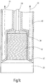
- Fig. 2 shows an embodiment of a sensor device in which the in Fig. 1 shown electronic components do not connect directly to the heat sink, but are provided outside the sensor device. Only the supply lines 32 are guided through the heat pipe 40 'and the heat sink 22' to the coils 24, 26, 28. The coupling of the heat sink 22 'to the heat pipe 40' by means of a solder connection via a substantially disc-shaped coupling surface 42 '.
- an outer housing 48 of the sensor device is shown, wherein 40 'highly effective insulation material 50 is provided between the outer housing and the heat pipe.
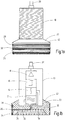
- Fig. 3a and b show a sensor housing 10 'and a heat sink 22 "in a basically the Fig. 1a and b appropriate arrangement.
- a single coil 52 is provided, which together with the electronic components 12, 16, 18 forms a resonant circuit.
- the coil 52 is also not arranged on the outer circumference of the heat sink 22 ", but in an annular recess 54 in the underside of the heat sink Fig. 1c screwed into a complementary recess of a heat pipe, wherein the heat dissipation via the coupling surface 42 of the heat sink 22 "takes place.
- Fig. 4 essentially shows one Fig. 2 corresponding embodiment, that is, the electronic components 12 to 18 are arranged outside the sensor device here as well.
- the heat sink 56 is not made in one piece, but consists of three annular bodies and three planar coils 58, 60, 62 are provided, which are arranged on or between the annular bodies of the heat sink 56 in a sandwich construction.
- the connection of the heat sink 56 to the heat pipe 40 "takes place by means of a solder connection along the axially and radially oriented coupling surfaces 64, 66.
- Fig. 5a to c show a further embodiment, which is largely in Fig. 1a to c shown, but in which between the heat sink 22 and the heat pipe 40, a coupling element 68 is interposed.
- the coupling element like the heat pipe, consists of copper or another metal with high thermal conductivity and has a heat sink side coupling surface 70 and a heat pipe side coupling surface 70 '.
- the connection to the heat sink 22 by means of soldering permanently, while the coupling to the heat pipe 40 by a surface pressure by means of screwing the composite of the heat sink and coupling element into the heat pipe 40 takes place.
- the coupling element 68 has engagement surfaces 72 for a tool, for example an open-end wrench.
- the coupling of the heat sink 22 to the heat pipe is not permanently via a soldering, but that the Sensor device can be easily decomposed into the essential components, for example, to replace a defective sensor module or to install a sensor module and / or coil variant for another measuring arrangement.
- the use of a correspondingly shaped coupling element is of course also in the embodiments according to Fig. 1 to 4 possible.
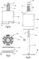
- a further preferred embodiment of the invention is in the Fig. 6 and 7 shown.
- the heat sink 100 of this embodiment is substantially cylindrical (but could also be cuboid o. The like. Be formed) and has a central through hole 102 and four symmetrically arranged blind holes 104 on.
- the passage bore 102 is intended for a tension member 106, with which a coil assembly 108 is pressed by spring force against an end face of the heat sink 100.
- a heat conducting film 110 is arranged between them.
- the four blind holes 104 receive end portions of heat pipes 112 which dissipate the heat absorbed by the heat sink 100.
- the contacting between the heat pipes 112 and the heat sink 100 can be done by shrinking, gluing or soldering.
- the tension member 106 is formed by four wire sections 114, which at the same time represent the electrical leads from the sensor electronics to the coil assembly 108.
- the coil assembly comprises as in Fig. 7c 1, a disk-shaped substrate 116 made of FR4 glass-fiber-reinforced epoxy laminate or of aluminum nitride ceramic is shown, on each of which one of two copper coils 118, 120 is applied by printing on both sides. In the central region of the substrate 116 are four holes for the passage of the wire sections 114, which are soldered there with contact ends of the coils 118, 120.
- the four wire sections 114 pass through channels 122 of an aluminum oxide ceramic guide sleeve 124, which extends between the coil assembly 108 and a spring assembly 126 arranged on the opposite end face of the heat sink 100.
- the pulling device is completed by a plated-through locking disc 128, with which the wire sections 114 are soldered, wherein the spring assembly 126 is biased.
- the spring package 126 comprises a helical spring 130 which is bounded on the end by two disks 132.
- the coil assembly 108 and the adjacent end region of the cooling body 100 are provided with a heat-conductive protective coating 134, the aluminum nitride and / or diamond particles contains.
- the heat sink may be made of an aluminum nitride ceramic, ferrite, a composite of ferrite and carbonaceous material, such as graphite, or a composite of aluminum nitride and diamond. Preference is given to those materials which have a high thermal conductivity, thermal stability (depending on the application temperature) and low electrical conductivity.
- the invention relates to a sensor device with a housing 48 for a at least two coils 58, 60, 62, 118, 120 having, preferably inductive sensor 10 for non-contact distance measurement to electrically conductive objects, wherein the sensor does not exceed a maximum operating temperature may.
- a heat sink 56, 100, 118 on the one hand as a support for the at least two electrical coils of the sensor and on the other hand as a connecting element to a heat conduction system 40 ", 112 is arranged for dissipating heat to a side facing away from the object to be measured portion of the housing.
Landscapes
- Physics & Mathematics (AREA)
- General Physics & Mathematics (AREA)
- Measuring Temperature Or Quantity Of Heat (AREA)
Description
- Die Erfindung betrifft eine Sensoreinrichtung mit einem Gehäuse für einen mindestens eine Spule aufweisenden, vorzugsweise induktiven Sensor zur berührungslosen Abstandsmessung zu elektrisch leitfähigen Objekten, wobei der Sensor eine maximale Betriebstemperatur nicht überschreiten darf.
- Derartige Sensoren sind als Einheit im Handel verfügbar und umfassen in einem Kapselgehäuse mindestens eine Induktionsspule und elektronische Komponenten wie einen Oszillator, einen Integrator sowie einen Verstärker zum Beaufschlagen der mindestens einen Spule mit einer Wechselspannung. In der Nähe von leitenden Objekten erfährt das von der Spule erzeugte Wechselfeld eine Dämpfung, aus deren Größe letztlich auf den Abstand zu dem leitenden Gegenstand geschlossen werden kann. Eine zuverlässige Messung ist jedoch nur in einem begrenzten Abstand zu dem leitenden Objekt möglich, so dass beispielsweise bei einer Füllstandsmessung von Metallschmelztiegeln o. dgl. der Messabstand nicht so groß gewählt werden kann, dass der Sensor seine zugelassene Temperaturbelastung, typischerweise nicht mehr als etwa 80 °C, einhalten könnte. Um den Sensor vor zu starker Wärmeeinwirkung zu schützen und gleichzeitig den erforderlichen Messabstand einhalten zu können, wurde in der
DE 10 2009 048 248 A1 bereits eine Anordnung des Sensors in einem Gehäuse mit Kühlmitteln vorgeschlagen. - Die Aufgabe der vorliegenden Erfindung besteht darin, eine Einrichtung der genannten Art weiter zu entwickeln und insbesondere hinsichtlich der zulässigen Höchsttemperatur des zu messenden Objekts zu verbessern.
- Zur Lösung dieser Aufgabe wird die in Patentanspruch 1 angegebene Merkmalskombination vorgeschlagen. Vorteilhafte Ausgestaltungen und Weiterentwicklungen der Erfindung ergeben sich aus den abhängigen Ansprüchen.
- Die Erfindung geht vor allem von dem Gedanken aus, zur Erhöhung des Messabstands den Spulendurchmesser zu vergrößern, der bislang durch das Kapselgehäuse des Sensors begrenzt ist. Erfindungsgemäß wird daher vorgeschlagen, dass in dem Gehäuse ein Kühlkörper einerseits als Träger für die mindestens eine elektrische Spule des Sensors und andererseits als Verbindungselement zu einem Wärmeleitsystem zum Ableiten von Wärme zu einen dem zu messenden Objekt abgewandten Bereich des Gehäuses angeordnet ist. Das ohnehin in dem Gehäuse vorhandene, zwischen einem Messfenster des Gehäuses und dem Kapselgehäuse des Sensors angeordnete Bauteil "Kühlkörper" übernimmt damit eine zusätzliche Funktion. Da die Spule die am wenigsten temperaturempfindliche Komponente des Sensors ist, ist es für deren Kühlung hinreichend, wenn sie beispielsweise eng anliegend auf den Außenumfang des Kühlkörpers gewickelt ist.
- Von großer Bedeutung bei gegenüber dem Stand der Technik erhöhten Messtemperaturen ist eine thermisch gute Ankopplung des Kühlkörpers an mindestens ein Wärmerohr der Sensoreinrichtung, welches Wärme vom spulenseitigen Ende des Gehäuses zum dem Objekt abgewandten Ende des Gehäuses transportiert. Bevorzugt ist der Kühlkörper mittels einer Lötverbindung mit dem mindestens einen Wärmerohr verbunden. In unterschiedlichen Varianten der Erfindung kann eine Mehrzahl kleinerer Wärmerohre anstatt eines einzelnen, vergleichsweise großen Wärmerohrs verwendet werden.
- Um eine einfache Demontage des Kühlkörpers zum Austausch von Sensorkomponenten zu ermöglichen, ist gemäß einer alternativen Ausgestaltung der Erfindung der Kühlkörper nicht direkt mit dem Wärmerohr verbunden, sondern mit einem Koppelelement, das seinerseits mit dem Wärmerohr koppelbar ist. Zweckmäßig ist das Koppelelement dann mit dem Wärmerohr verschraubt oder verrastet oder mittels einer Bajonettverbindung verbunden. Der Kühlkörper seinerseits kann dabei mit dem Koppelelement durch eine Lötverbindung oder eine Schrumpfverbindung verbunden sein.
- Um eine mechanische Belastung des Kühlkörpers bzw. der Lötverbindung bei der Montage der Kombination aus Kühlköper und Koppelelement an dem Wärmerohr zu vermeiden, weist das Koppelelement in bevorzugter Ausgestaltung der Erfindung Mittel zum Ansetzen eines Werkzeugs auf. Beispielsweise kann das Koppelelement Flächen zum Ansetzen eines Schraubenschlüssels oder mindestens eine Vertiefung zum Ansetzen eines Haken- oder Stiftschlüssels aufweisen. Zusätzlich kann eine mechanische Sicherung gegen ungewolltes Lösen oder Wiederöffnen der Verbindung zwischen dem Koppelelement und dem Wärmerohr vorgesehen sein, da die Sensoreinrichtung Vibrationen ausgesetzt sein kann und chemische Sicherungsmittel für Schraubverbindungen einerseits den Wärmefluss behindern könnten und andererseits den hohen Einsatztemperaturen der Sensoreinrichtung nicht standhalten.
- In weiterer Ausgestaltung der Erfindung kann die mindestens eine Spule galvanisch, etwa über Anschlussdrähte oder Leiterbahnen mit einer außerhalb des Wärmeleitsystems angeordneten Elektronikeinheit zum Beaufschlagen der mindestens einen Spule mit einer elektrischen Wechselspannung ver-bunden sein. Die Elektronik kann damit in einen kühlen Bereich verlagert werden, da sie nur bis etwa 80 °C belastbar ist, während die Spule bis etwa 300 °C belastbar ist.
- Die Ankopplungsfläche des Kühlkörpers bzw. des Koppelelements an das Wärmerohr kann axial und/oder radial ausgerichtet sein und beispielsweise ringförmig ausgebildet sein.
- Der den mit am höchsten Temperaturen ausgesetzte Kühlkörper besteht in bevorzugter Ausgestaltung der Erfindung aus einer Aluminiumnitridkeramik, alternativ auch aus Ferrit oder einem Verbundwerkstoff umfassend umfassend Ferrit und kohlenstoffhaltiges Material, insbesondere Graphit. Aluminiumnitridkeramik weist den Vorteil höchster Temperaturbelastbarkeit auf, währen ein Ferritwerkstoff das Spulenfeld verstärkt und damit einen noch größeren Messabstand erlaubt, als bereits durch den erfindungsgemäß vergrößerten Spulendurchmesser ermöglicht wird. Die Sensoreinrichtung ist damit an verschiedenste Messumgebungen anpassbar.Gemäß der Erfindung besteht der Kühlkörper aus mindestens zwei Schichten, auf und/oder zwischen denen die Spule in ebener Konfiguration angeordnet ist.
- In Abhängigkeit von unterschiedlichen verwendeten Messverfahren kann eine einzige Spule vorgesehen sein und die Messung auf einer Verstimmung oder Dämpfung eines die Spule umfassenden Schwingkreises beruhen, oder es können eine Sendespule und zwei Empfangsspulen zur Anwendung eines Differenzmessverfahrens vorgesehen sein, wobei die drei Spulen axial in der Reihenfolge Empfangsspule-Sendespule-Empfangsspule angeordnet sind.
- In einer weiteren alternativen Ausgestaltung der Erfindung werden zwei ringförmig geschlossene Mäanderspulen verwendet, die hinsichtlich ihrer Mäander deckungsgleich oder um einen Winkel zueinander versetzt angeordnet sind. Derartige Spulenanordnungen sind grundsätzlich bekannt und in abgewandelter aber funktionsähnlicher Geometrie beispielsweise in der
DE 10 2009 021 804 A1 oderDE 10 2009 029 928 A1 für den Anwendungsfall eines Metalldetektors beschrieben. Vorliegend können die aufgrund ihrer Leistungscharakteristik bevorzugten Mäanderspulen ebenfalls durch abgewandelte Geometrien ersetzt werden. - Die zwei Spulen sind zweckmäßig als Kupferprintspulen auf je einer Seite eines scheibenförmigen Kunststoffsubstrats, vorzugsweise eines FR4 glasfaserverstärkten Epoxylaminatsubstrats, oder eines Aluminiumnitrid Keramiksubstrats ausgebildet.
- Bei einer weiteren besonders bevorzugten Ausführungsform der Erfindung weist der Kühlkörper eine zentrale Durchtrittsbohrung auf, durch die ein federbelastetes Zugorgan hindurchtritt, das einen aus zwei je auf einer Seite eines Substrats angeordneten Spulen bestehenden Spulenverbund gegen eine Stirnfläche des Kühlkörpers drückt. Das Anpressen des Spulenverbunds gegen den Kühlkörper weist den Vorteil auf, dass keine alterungsbedingten Kontaktbeeinträchtigungen wie beispielsweise eine Alterung und Versagen einer Klebstoffverbindung auftreten. Weiterhin werden durch Temperaturwechsel auftretende Spannungen durch die Feder kompensiert und die Montagezeit der Sensoreinrichtung wird verkürzt, da Aushärtezeiten einer Klebverbindung entfallen. Zweckmäßig ist zur Verbesserung des Wärmeübergangs eine Wärmeleitfolie zwischen dem Spulenverbund und dem Kühlkörper angeordnet.
- In vorteilhafter Ausgestaltung dieser Ausführungsform ist das Zugorgan durch vier Drahtabschnitte gebildet, die durch den Spulenverbund hindurchtreten und mit Anschlüssen der zwei Spulen elektrisch kontaktiert sind. Die Drahtabschnitte erfüllen damit sowohl die Funktion des Zugorgans als auch die Funktion der elektrischen Verbindung der Spulen mit der Sensorelektronik. Um einen Kurzschluss zwischen den vier Drahtabschnitten untereinander oder mit den weiteren Komponenten der Sensoreinrichtung zu vermeiden ist in bevorzugter Ausgestaltung der Erfindung eine in der Durchtrittsbohrung des Kühlkörpers angeordnete, aus einem elektrisch isolierenden Material, vorzugsweise aus Aluminiumoxidkeramik, bestehenden Führungshülse für die vier Drahtabschnitte vorgesehen. Die Führungshülse weist zweckmäßig vier voneinander getrennte Durchtrittskanäle für je einen der Drahtabschnitte auf.
- Um die Zugkraft der Feder auf den Spulenverbund zu übertragen, treten die dem Spulenverbund abgewandten Enden der vier Drahtabschnitte in vorteilhafter Ausgestaltung der Erfindung unter Zwischenschaltung eines Federpakets durch eine Arretierscheibe hindurch und sind mit dieser verbunden, vorzugsweise verlötet. Das Federpaket umfasst vorteilhaft eine Schraubenfeder und zwei die Schraubenfeder endseitig begrenzende Scheiben. Die Führungshülse für die Drahtabschnitte tritt auch durch das Federpaket hindurch um dort einen möglichen Kurzschluss mit den Drahtabschnitten zu verhindern.
- Der Kühlkörper dieser Ausführungsform der Erfindung besteht bevorzugt aus Aluminiumnitridkeramik. Um ein Eindringen von Partikeln in den Bereich des Spulenverbunds und eine ungewollte Verschiebung des Spulenverbunds bei der Montage zu vermeiden, ist der Spulenverbund zusammen mit einem Endbereich des Kühlkörpers in vorteilhafter Ausgestaltung der Erfindung mit einem wärmeleitfähigen Schutzüberzug versehen. Um einen möglichst günstigen Wärmeübergang zu erreichen, kann der Schutzüberzug Aluminiumnitrid- und/oder Diamantpartikel enthalten.
- Im Folgenden wird die Erfindung anhand der in der Zeichnung in schematischer Weise dargestellten Ausführungsbeispiele näher erläutert. Es zeigen
- Fig. 1a bis
- c eine Seitenansicht und eine Schnittansicht eines Messmoduls mit drei auf einem Kühlkörper angeordneten Spulen, sowie eine Schnittansicht des an ein Wärmerohr angekoppelten Messmoduls;
- Fig. 2
- eine Schnittansicht eines Beispiels einer Sensoreinrichtung bei der die Elektronikkomponenten außerhalb des Gehäuses angeordnet sind;
- Fig. 3a
- und b eine Darstellung entsprechend
Fig. 1a und b mit einer abgewandelten Ausführungsform des Kühlkörpers und einer einzigen Spule; - Fig. 4
- eine
Fig. 2 entsprechende Darstellung einer abgewandelten Ausführungsform des Kühlkörpers gemäß der Erfindung mit Spulen in einer Sandwichanordnung; - Fig. 5a
- bis c teilweise geschnittene Seitenansichten eines Messmoduls bei dem ein Koppelelement zwischen dem Kühlkörper und dem Wärmerohr vorgesehen ist:
- Fig. 6a
- bis c eine weitere Ausführungsform der Erfindung mit vier Wärmerohren und einem durch Federkraft an den Kühlkörper angekoppelten Spulenverbund; und
- Fig. 7a
- bis c eine Seitenansicht und eine Explosionsdarstellung der Ausführungsform gemäß
Fig. 6 . - Das in
Fig. 1 dargestellte Sensor- oder Messmodul besteht im Wesentlichen aus einem mit einem Außengewinde versehenen Sensorgehäuse 10 aus Messing, in dem die elektronischen Komponenten des Sensors angeordnet sind. Die umfassen einen Oszillator 12, einen Integrator 14, eine Auswerteinheit 16 und einen Verstärker 18. Die Energieversorgung des Sensormoduls und die Messwertabnahme erfolgt über ein aus der Sensoreinrichtung herausgeführtes Sensoranschlusskabel 20. Das Gehäuse 10 ist in einen Kühlkörper 22 eingepasst, der gleichzeitig auf seinem Außenumfang drei Spulen 24, 26, 28 trägt, von denen die mittlere Spule 26 als Sendespule und die äußeren Spulen 24 und 28 als Empfangsspulen ausgebildet sind. Die Spulen 24, 26, 28 sind über durch eine Zentralbohrung 30 geführte Zuführleitungen 32 mit dem Sensormodul verbunden. Der Kühlkörper 22 weist eine bodenseitige, topfförmige Ausnehmung 34 auf, in der thermisches Isolationsmaterial 36 angeordnet ist. Wie derFig. 1c zu entnehmen ist, ist das Sensormodul in eine zum Gehäuse 10 komplementäre Ausnehmung 38 eines Wärmerohrs 40 eingeschraubt. Die Ausnehmung 38 weist zu diesem Zweck ein dem Außengewinde des Gehäuses 10 entsprechendes Innengewinde auf. Die Wärmeübertragung zwischen dem Kühlkörper 22 und dem Wärmerohr 40 erfolgt über eine Koppelfläche 42 des Kühlkörpers 22. Der Wärmetransport findet von dem warmen Ende der Einrichtung in Richtung der Pfeile 44 zum kalten Ende der Einrichtung statt und wird dort beispielsweise über einen Wärmeableitkörper 46 (Fig. 2 ) an die Umgebung abgeführt. -
Fig. 2 zeigt eine Ausführungsform einer Sensoreinrichtung, bei der die inFig. 1 dargestellten Elektronikkomponenten nicht unmittelbar an den Kühlkörper anschließen, sondern außerhalb der Sensoreinrichtung vorgesehen sind. Lediglich die Zuführleitungen 32 sind durch das Wärmerohr 40' und den Kühlkörper 22' hindurch zu den Spulen 24, 26, 28 geführt. Die Ankopplung des Kühlkörpers 22' an das Wärmerohr 40' erfolgt mittels einer Lötverbindung über eine im Wesentlichen scheibenförmige Koppelfläche 42'. In dieserFig. 2 ist weiterhin ein Außengehäuse 48 der Sensoreinrichtung gezeigt, wobei zwischen dem Außengehäuse und dem Wärmerohr 40' hochwirksames Isolationsmaterial 50 vorgesehen ist. -
Fig. 3a und b zeigen ein Sensorgehäuse 10' und einen Kühlkörper 22" in einer grundsätzlich denFig. 1a und b entsprechenden Anordnung. Hier ist jedoch eine einzelne Spule 52 vorgesehen, die zusammen mit den Elektronikkomponenten 12, 16, 18 einen Schwingkreis bildet. Die Spule 52 ist auch nicht auf dem Außenumfang des Kühlkörpers 22" angeordnet, sondern in einer Ringausnehmung 54 in der Unterseite des Kühlkörpers. Das Sensorgehäuse 10' wird wie inFig. 1c in eine komplementäre Ausnehmung eines Wärmerohrs eingeschraubt, wobei die Wärmeableitung über die Koppelfläche 42 des Kühlkörpers 22" erfolgt. -
Fig. 4 zeigt eine im WesentlichenFig. 2 entsprechende Ausführungsform, das heißt auch hier sind die Elektronikkomponenten 12 bis 18 außerhalb der Sensoreinrichtung angeordnet. Der Kühlkörper 56 ist jedoch gemäß der Erfindung nicht einstückig ausgeführt, sondern besteht aus drei Ringkörpern und es sind drei planare Spulen 58, 60, 62 vorgesehen, die auf bzw. zwischen den Ringkörpern des Kühlkörpers 56 in einer Sandwichbauweise angeordnet sind. Die Verbindung des Kühlkörpers 56 zum Wärmerohr 40" erfolgt mittels einer Lötverbindung entlang der axial und radial orientierten Koppelflächen 64, 66. -
Fig. 5a bis c zeigen eine weitere Ausführungsform, die weitgehend der inFig. 1a bis c dargestellten entspricht, bei der jedoch zwischen dem Kühlkörper 22 und dem Wärmerohr 40 ein Koppelelement 68 zwischengeordnet ist. Das Koppelelement besteht wie das Wärmerohr aus Kupfer oder einem anderen Metall mit hoher thermischer Leitfähigkeit und weist eine kühlkörperseitige Koppelfläche 70 und eine wärmerohrseitige Koppelfläche 70' auf. Die Verbindung mit dem Kühlkörper 22 erfolgt mittels Löten dauerhaft, während die Ankopplung an das Wärmerohr 40 durch eine Flächenpressung mittels Verschraubung des Verbunds aus Kühlkörper und Koppelelement in das Wärmerohr 40 erfolgt. Das Koppelelement 68 weist Angriffsflächen 72 für ein Werkzeug, beispielsweise einen Maulschlüssel auf. Hierdurch kann die Verschraubung mit höherer Kraft erfolgen, als wenn die Schraubkraft über den Kühlkörper 22 eingeleitet werden würde. Ebenfalls von großem Vorteil ist, dass die Ankopplung des Kühlkörpers 22 an das Wärmerohr nicht dauerhaft über eine Verlötung erfolgt, sondern dass die Sensoreinrichtung auf einfache Weise in die wesentlichen Komponenten zerlegt werden kann, beispielsweise um ein defektes Sensormodul auszutauschen oder ein Sensormodul und/oder Spulenvariante für eine andere Messanordnung zu installieren. Die Verwendung eines entsprechend gestalteten Koppelelements ist selbstverständlich auch bei den Ausführungsformen gemäßFig. 1 bis 4 möglich. - Eine weitere bevorzugte Ausführungsform der Erfindung ist in den
Fig. 6 und7 dargestellt. - Der Kühlkörper 100 dieser Ausführungsform ist im Wesentlichen zylinderförmig (könnte jedoch auch quaderförmig o. dgl. ausgebildet sein) und weist eine zentrale Durchtrittsbohrung 102 und vier dazu symmetrisch angeordnete Sacklöcher 104 auf. Die Durchtrittsbohrung 102 ist für ein Zugorgan 106 bestimmt, mit dem ein Spulenverbund 108 durch Federkraft gegen eine Stirnfläche des Kühlkörpers 100 gepresst wird. Zur Verbesserung der thermischen Ankopplung des Spulenverbunds 108 an den Kühlkörper 100 ist zwischen diesen eine Wärmeleitfolie 110 angeordnet. Die vier Sacklöcher 104 nehmen Endbereiche von Wärmerohren 112 auf, die die vom Kühlkörper 100 aufgenommene Wärme ableiten. Die Kontaktierung zwischen den Wärmerohren 112 und dem Kühlkörper 100 kann durch Schrumpfen, Kleben oder Löten erfolgen.
- Das Zugorgan 106 ist durch vier Drahtabschnitte 114 gebildet, die zugleich die elektrischen Zuleitungen von der Sensorelektronik zu dem Spulenverbund 108 darstellen. Der Spulenverbund umfasst wie in
Fig. 7c dargestellt ein scheibenförmiges Substrat 116 aus FR4 glasfaserverstärktem Epoxylaminat oder aus Aluminiumnitridkeramik, auf das beidseitig je eine von zwei Kupferspulen 118, 120 im Printverfahren aufgebracht ist. Im mittleren Bereich des Substrats 116 sind vier Bohrungen für den Durchtritt der Drahtabschnitte 114 vorgesehen, die dort mit Kontaktenden der Spulen 118, 120 verlötet sind. - Die vier Drahtabschnitte 114 treten durch Kanäle 122 einer Führungshülse 124 aus Aluminiumoxidkeramik hindurch, die sich zwischen dem Spulenverbund 108 und einem an der gegenüberliegenden Stirnfläche des Kühlkörpers 100 angeordneten Federpaket 126 erstreckt. Abgeschlossen wird die Zugeinrichtung durch eine durchkontaktierte Arretierscheibe 128, mit der die Drahtabschnitte 114 verlötet sind, wobei das Federpaket 126 vorgespannt wird. Das Federpaket 126 umfasst eine Schraubenfeder 130, die endseitig von zwei Scheiben 132 begrenzt wird.
- Um ein Eintreten von Partikeln in den Bereich des Spulenverbunds 108 zu verhindern und diesen bei der Montage im Sensorgehäuse 48 vor Verschiebungen zu schützen sind der Spulenverbund 108 und der benachbarte Endbereich des Kühlkörpers 100 mit einem wärmeleitenden Schutzüberzug 134 versehen, der Aluminiumnitrid- und/oder Diamantpartikel enthält.
- Bei sämtlichen der vorstehend beschriebenen Ausführungsformen kann der Kühlkörper aus einer Aluminiumnitridkeramik, aus Ferrit, aus einem Verbundwerkstoff aus Ferrit und kohlenstoffhaltigem Material, beispielsweise Graphit, oder aus einem Verbundwerkstoff aus Aluminiumnitrid und Diamant bestehen. Bevorzugt sind solche Materialien, die eine hohe Wärmeleitfähigkeit, Temperaturbelastbarkeit (je nach Einsatztemperatur) und geringe elektrische Leitfähigkeit aufweisen.
- Zusammenfassend ist folgendes festzuhalten: Die Erfindung betrifft eine Sensoreinrichtung mit einem Gehäuse 48 für einen mindestens zwei Spulen 58, 60, 62, 118, 120 aufweisenden, vorzugsweise induktiven Sensor 10 zur berührungslosen Abstandsmessung zu elektrisch leitfähigen Objekten, wobei der Sensor eine maximale Betriebstemperatur nicht überschreiten darf. Um die Sensoreinrichtung bei höheren Temperaturen des Messobjekts verwenden zu können, wird gemäß der Erfindung vorgeschlagen, dass in dem Gehäuse ein Kühlkörper 56, 100, 118 einerseits als Träger für die mindestens zwei elektrischen Spulen des Sensors und andererseits als Verbindungselement zu einem Wärmeleitsystem 40", 112 zum Ableiten von Wärme zu einen dem zu messenden Objekt abgewandten Bereich des Gehäuses angeordnet ist.
Claims (14)
- Sensoreinrichtung mit einem Gehäuse (48) für einen mindestens zwei Spulen (58, 60, 62, 118, 120) aufweisenden, vorzugsweise induktiven Sensor (10) zur berührungslosen Abstandsmessung zu elektrisch leitfähigen Objekten, wobei der Sensor eine maximale Betriebstemperatur nicht überschreiten darf, wobei in dem Gehäuse (48) ein Kühlkörper (56, 100, 116) einerseits als Träger für die mindestens zwei elektrischen Spulen des Sensors und andererseits als Verbindungselement zu einem Wärmeleitsystem (40", 112) zum Ableiten von Wärme zu einen dem zu messenden Objekt abgewandten Bereich des Gehäuses (48) angeordnet ist, dadurch gekennzeichnet dass der Kühlkörper (56, 100, 116) nicht einstückig ausgeführt ist, sondern aus mindestens zwei Schichten besteht, auf und/oder zwischen denen die mindestens zwei Spulen (58, 60, 62, 118, 120) angeordnet sind.
- Sensoreinrichtung nach Anspruch 1, dadurch gekennzeichnet, dass der Kühlkörper (56, 100, 116) an mindestens ein Wärmerohr (40", 112) angekoppelt ist, welches Wärme vom spulenseitigen Ende des Gehäuses (48) zum dem Objekt abgewandten Ende des Gehäuses transportiert.
- Sensoreinrichtung nach Anspruch 2, dadurch gekennzeichnet, dass der Kühlkörper (56, 100, 116) mittels einer Lötverbindung mit dem mindestens einen Wärmerohr (40", 112) verbunden ist oder dass der Kühlkörper (56, 100, 116) mit einem Koppelelement (68) verbunden ist, das seinerseits mit dem mindestens einen Wärmerohr (40") koppelbar ist, und dass das Koppelelement (68) mit dem mindestens einen Wärmerohr (40") verschraubt oder verrastet ist oder mittels einer Bajonettverbindung verbunden ist.
- Sensoreinrichtung nach einem der Ansprüche 1 bis 3, dadurch gekennzeichnet, dass mindestens eine der Spulen (58, 60, 62, 118, 120) galvanisch mit einer außerhalb des Wärmeleitsystems angeordneten Elektronikeinheit zum Beaufschlagen der mindestens einen Spule mit einer elektrischen Wechselspannung verbunden ist.
- Sensoreinrichtung nach einem der Ansprüche 1 bis 4, dadurch gekennzeichnet, dass der Kühlköper (56, 110, 116) für die Spulen (58, 60, 62, 118, 120) aus einer Aluminiumnitridkeramik oder aus Ferrit oder aus einem Verbundwerkstoff umfassend Ferrit und kohlenstoffhaltiges Material, insbesondere Graphit, besteht.
- Sensoreinrichtung nach einem der Ansprüche 1 bis 5, dadurch gekennzeichnet, dass eine Sendespule und zwei Empfangsspulen zur Anwendung eines Differenzmessverfahrens vorgesehen sind.
- Sensoreinrichtung nach Anspruch 6, dadurch gekennzeichnet, dass die drei Spulen (58, 60, 62) axial in der Reihenfolge Empfangsspule-Sendespule-Empfangsspule angeordnet sind.
- Sensoreinrichtung nach einem der Ansprüche 1 bis 5, gekennzeichnet durch zwei ringförmig geschlossene Mäanderspulen (118, 120), die hinsichtlich ihrer Mäander deckungsgleich oder um einen Winkel zueinander versetzt angeordnet sind.
- Sensoreinrichtung nach Anspruch 8, dadurch gekennzeichnet, dass die zwei Spulen (118, 120) als Kupferprintspulen auf je einer Seite eines scheibenförmigen Kunststoffsubstrats (116), vorzugsweise eines FR4 glasfaserverstärkten Epoxylaminatsubstrats, oder eines Aluminiumnitrid Keramiksubstrats ausgebildet sind.
- Sensoreinrichtung nach einem der Ansprüche 1 bis 3 oder 8 und 9, dadurch gekennzeichnet, dass der Kühlkörper (100) eine zentrale Durchtrittsbohrung (102) aufweist, durch die ein federbelastetes Zugorgan (106) hindurchtritt, das einen aus zwei je auf einer Seite eines Substrats (116) angeordneten Spulen (118, 120) bestehenden Spulenverbund (108) gegen eine Stirnfläche des Kühlkörpers (100) drückt.
- Sensoreinrichtung nach Anspruch 10, dadurch gekennzeichnet, dass der Kühlkörper (100) eine Mehrzahl von die Durchtrittsbohrung (102) umgebende, vorzugsweise als Sacklöcher ausgebildete Bohrungen (104) zur Aufnahme von Wärmerohren (112) aufweist und dass zwischen dem Spulenverbund (108) und dem Kühlkörper (100) eine Wärmeleitfolie (110) angeordnet ist.
- Sensoreinrichtung nach Anspruch 10 oder 11, dadurch gekennzeichnet, dass das Zugorgan (106) durch vier Drahtabschnitte (114) gebildet ist, die durch den Spulenverbund (108) hindurchtreten und mit Anschlüssen der zwei Spulen (118, 120) elektrisch kontaktiert sind.
- Sensoreinrichtung nach Anspruch 12, dadurch gekennzeichnet, dass die dem Spulenverbund (108) abgewandten Enden der vier Drahtabschnitte (114) unter Zwischenschaltung eines Federpakets (126) durch eine Arretierscheibe (128) hindurchtreten und mit dieser verbunden, vorzugsweise verlötet, sind.
- Sensoreinrichtung nach einem der Ansprüche 10 bis 13, dadurch gekennzeichnet, dass der Kühlkörper (100) aus Aluminiumnitridkeramik besteht.
Applications Claiming Priority (2)
| Application Number | Priority Date | Filing Date | Title |
|---|---|---|---|
| DE102012012680.8A DE102012012680A1 (de) | 2012-06-27 | 2012-06-27 | Sensoreinrichtung |
| PCT/EP2013/063571 WO2014001479A1 (de) | 2012-06-27 | 2013-06-27 | Sensoreinrichtung |
Publications (2)
| Publication Number | Publication Date |
|---|---|
| EP2867623A1 EP2867623A1 (de) | 2015-05-06 |
| EP2867623B1 true EP2867623B1 (de) | 2017-05-10 |
Family
ID=48700585
Family Applications (1)
| Application Number | Title | Priority Date | Filing Date |
|---|---|---|---|
| EP13732161.8A Not-in-force EP2867623B1 (de) | 2012-06-27 | 2013-06-27 | Sensoreinrichtung |
Country Status (3)
| Country | Link |
|---|---|
| EP (1) | EP2867623B1 (de) |
| DE (1) | DE102012012680A1 (de) |
| WO (1) | WO2014001479A1 (de) |
Families Citing this family (4)
| Publication number | Priority date | Publication date | Assignee | Title |
|---|---|---|---|---|
| US10145873B2 (en) | 2014-06-30 | 2018-12-04 | Rockwell Automation Technologies, Inc. | Coil architecture for inductive sensors |
| CN106815988A (zh) * | 2017-01-20 | 2017-06-09 | 奇酷互联网络科技(深圳)有限公司 | 移动终端及其拆解判断方法和装置 |
| CN108107055B (zh) * | 2017-11-20 | 2019-11-15 | 珠海格力电器股份有限公司 | 智能功率模块的控制方法、装置、存储介质和处理器 |
| CN114137022B (zh) * | 2021-11-30 | 2025-01-28 | 重庆大学 | 一种热电堆型热流密度传感器 |
Family Cites Families (7)
| Publication number | Priority date | Publication date | Assignee | Title |
|---|---|---|---|---|
| DE2602045A1 (de) * | 1976-01-21 | 1977-07-28 | Hiss Eckart | Detektor kuehlvorrichtung fuer beruehrungslose naeherungsinitiatoren |
| DE4212652C2 (de) * | 1992-04-15 | 1994-06-30 | Weidmueller Interface | Laserbearbeitungskopf mit induktivem Abstandssensor |
| US6617845B1 (en) * | 2000-04-28 | 2003-09-09 | Rockwell Automation Technologies, Inc. | Proximity sensor resistant to environmental effects |
| DE102009029928A1 (de) | 2009-06-19 | 2010-12-23 | Gerd Reime | Metalldetektor |
| DE102009021804A1 (de) | 2009-05-18 | 2010-11-25 | Gerd Reime | Metalldetektor |
| GB0915670D0 (en) * | 2009-09-08 | 2009-10-07 | Perception Sensors & Instrumen | High temperature operation inductive positioning device |
| DE102009048248A1 (de) | 2009-10-05 | 2011-06-09 | Hartmann, Eva | Kühleinrichtung für einen bei erhöhter Umgebungstemperatur einsetzbaren Sensor |
-
2012
- 2012-06-27 DE DE102012012680.8A patent/DE102012012680A1/de not_active Withdrawn
-
2013
- 2013-06-27 WO PCT/EP2013/063571 patent/WO2014001479A1/de not_active Ceased
- 2013-06-27 EP EP13732161.8A patent/EP2867623B1/de not_active Not-in-force
Also Published As
| Publication number | Publication date |
|---|---|
| DE102012012680A1 (de) | 2014-01-02 |
| WO2014001479A1 (de) | 2014-01-03 |
| EP2867623A1 (de) | 2015-05-06 |
Similar Documents
| Publication | Publication Date | Title |
|---|---|---|
| DE69323126T2 (de) | Schutzsensor für Elektromotor | |
| DE69907493T2 (de) | Oberflächentemperatursensor | |
| EP2527807B1 (de) | Temperaturfühler für ein Kontaktthermometer | |
| EP2867623B1 (de) | Sensoreinrichtung | |
| EP1842407A1 (de) | Steuermodul | |
| DE102013226232A1 (de) | Handwerkzeugakku | |
| EP2643668A1 (de) | Elektrischer steckverbinder für thermoelemente und verfahren zu dessen herstellung | |
| EP4078120A1 (de) | Sensorvorrichtung, elektrische einrichtung mit sensorvorrichtung und fahrzeug mit sensorvorrichtung | |
| DE112018003222T5 (de) | Halbleitermodul | |
| WO2017182293A1 (de) | Temperatursensor, batteriesystem und verfahren zum montieren eines batteriesystems | |
| DE102009056699A1 (de) | Autonomer Temperaturtransmitter | |
| EP3087313B1 (de) | Explosionsgeschützte anordnung für elektrische und/oder elektronische bauelemente | |
| DE102013211640A1 (de) | Optoelektronische Anordnung | |
| DE10065495C2 (de) | Leistungshalbleitermodul | |
| DE102015104170A1 (de) | Anschlusssteckvorrichtung | |
| DE202015106844U1 (de) | Stecker mit einem Fahrzeugladekabel eines Elektro- oder Hybridfahrzeuges | |
| DE102012209034A1 (de) | Elektronikmodul sowie Verfahren zur Herstellung eines solchen Elektronikmoduls, sowie elektronisches Steuergerät mit einem solchen Elektronikmodul | |
| EP2737326B1 (de) | Schaltung zum leiten eines elektrischen stromes | |
| EP4384789B1 (de) | Unterlegscheibe sowie schraubverbindungssystem | |
| DE102006062599A1 (de) | Opto-elektronische Vorrichtung zur Übertragung eines elektrischen Signals | |
| DE102013219092B4 (de) | Anordnung eines Temperatursensors mit einer elektrisch isolierenden Umhüllung | |
| EP1568978B1 (de) | Temperatursensor | |
| EP2676347B1 (de) | Elektronisches gerät und schutzelement hierfür für den einsatz in explosionsgefährdeten bereichen | |
| EP3625805B1 (de) | Leistungswiderstand | |
| DE102017206146B4 (de) | Hochstrom-Steckbuchse und Hochstrom-Steckeranordnung mit einer Hochstrom-Steckbuchse |
Legal Events
| Date | Code | Title | Description |
|---|---|---|---|
| PUAI | Public reference made under article 153(3) epc to a published international application that has entered the european phase |
Free format text: ORIGINAL CODE: 0009012 |
|
| 17P | Request for examination filed |
Effective date: 20141023 |
|
| AK | Designated contracting states |
Kind code of ref document: A1 Designated state(s): AL AT BE BG CH CY CZ DE DK EE ES FI FR GB GR HR HU IE IS IT LI LT LU LV MC MK MT NL NO PL PT RO RS SE SI SK SM TR |
|
| AX | Request for extension of the european patent |
Extension state: BA ME |
|
| DAX | Request for extension of the european patent (deleted) | ||
| 17Q | First examination report despatched |
Effective date: 20160203 |
|
| GRAP | Despatch of communication of intention to grant a patent |
Free format text: ORIGINAL CODE: EPIDOSNIGR1 |
|
| INTG | Intention to grant announced |
Effective date: 20170120 |
|
| GRAS | Grant fee paid |
Free format text: ORIGINAL CODE: EPIDOSNIGR3 |
|
| GRAA | (expected) grant |
Free format text: ORIGINAL CODE: 0009210 |
|
| AK | Designated contracting states |
Kind code of ref document: B1 Designated state(s): AL AT BE BG CH CY CZ DE DK EE ES FI FR GB GR HR HU IE IS IT LI LT LU LV MC MK MT NL NO PL PT RO RS SE SI SK SM TR |
|
| REG | Reference to a national code |
Ref country code: GB Ref legal event code: FG4D Free format text: NOT ENGLISH |
|
| REG | Reference to a national code |
Ref country code: AT Ref legal event code: REF Ref document number: 892843 Country of ref document: AT Kind code of ref document: T Effective date: 20170515 Ref country code: CH Ref legal event code: EP |
|
| REG | Reference to a national code |
Ref country code: IE Ref legal event code: FG4D Free format text: LANGUAGE OF EP DOCUMENT: GERMAN |
|
| REG | Reference to a national code |
Ref country code: FR Ref legal event code: PLFP Year of fee payment: 5 |
|
| REG | Reference to a national code |
Ref country code: DE Ref legal event code: R096 Ref document number: 502013007235 Country of ref document: DE |
|
| REG | Reference to a national code |
Ref country code: NL Ref legal event code: MP Effective date: 20170510 |
|
| REG | Reference to a national code |
Ref country code: LT Ref legal event code: MG4D |
|
| PG25 | Lapsed in a contracting state [announced via postgrant information from national office to epo] |
Ref country code: ES Free format text: LAPSE BECAUSE OF FAILURE TO SUBMIT A TRANSLATION OF THE DESCRIPTION OR TO PAY THE FEE WITHIN THE PRESCRIBED TIME-LIMIT Effective date: 20170510 Ref country code: LT Free format text: LAPSE BECAUSE OF FAILURE TO SUBMIT A TRANSLATION OF THE DESCRIPTION OR TO PAY THE FEE WITHIN THE PRESCRIBED TIME-LIMIT Effective date: 20170510 Ref country code: GR Free format text: LAPSE BECAUSE OF FAILURE TO SUBMIT A TRANSLATION OF THE DESCRIPTION OR TO PAY THE FEE WITHIN THE PRESCRIBED TIME-LIMIT Effective date: 20170811 Ref country code: FI Free format text: LAPSE BECAUSE OF FAILURE TO SUBMIT A TRANSLATION OF THE DESCRIPTION OR TO PAY THE FEE WITHIN THE PRESCRIBED TIME-LIMIT Effective date: 20170510 Ref country code: HR Free format text: LAPSE BECAUSE OF FAILURE TO SUBMIT A TRANSLATION OF THE DESCRIPTION OR TO PAY THE FEE WITHIN THE PRESCRIBED TIME-LIMIT Effective date: 20170510 Ref country code: NO Free format text: LAPSE BECAUSE OF FAILURE TO SUBMIT A TRANSLATION OF THE DESCRIPTION OR TO PAY THE FEE WITHIN THE PRESCRIBED TIME-LIMIT Effective date: 20170810 |
|
| REG | Reference to a national code |
Ref country code: DE Ref legal event code: R082 Ref document number: 502013007235 Country of ref document: DE Representative=s name: PFIZ/GAUSS PATENTANWAELTE PARTMBB, DE Ref country code: DE Ref legal event code: R081 Ref document number: 502013007235 Country of ref document: DE Owner name: IAS GMBH INDUSTRIE AUTOMATIONSSYSTEME, DE Free format text: FORMER OWNER: HARTMANN, EVA, 71263 WEIL DER STADT, DE |
|
| PG25 | Lapsed in a contracting state [announced via postgrant information from national office to epo] |
Ref country code: BG Free format text: LAPSE BECAUSE OF FAILURE TO SUBMIT A TRANSLATION OF THE DESCRIPTION OR TO PAY THE FEE WITHIN THE PRESCRIBED TIME-LIMIT Effective date: 20170810 Ref country code: SE Free format text: LAPSE BECAUSE OF FAILURE TO SUBMIT A TRANSLATION OF THE DESCRIPTION OR TO PAY THE FEE WITHIN THE PRESCRIBED TIME-LIMIT Effective date: 20170510 Ref country code: RS Free format text: LAPSE BECAUSE OF FAILURE TO SUBMIT A TRANSLATION OF THE DESCRIPTION OR TO PAY THE FEE WITHIN THE PRESCRIBED TIME-LIMIT Effective date: 20170510 Ref country code: IS Free format text: LAPSE BECAUSE OF FAILURE TO SUBMIT A TRANSLATION OF THE DESCRIPTION OR TO PAY THE FEE WITHIN THE PRESCRIBED TIME-LIMIT Effective date: 20170910 Ref country code: PL Free format text: LAPSE BECAUSE OF FAILURE TO SUBMIT A TRANSLATION OF THE DESCRIPTION OR TO PAY THE FEE WITHIN THE PRESCRIBED TIME-LIMIT Effective date: 20170510 Ref country code: LV Free format text: LAPSE BECAUSE OF FAILURE TO SUBMIT A TRANSLATION OF THE DESCRIPTION OR TO PAY THE FEE WITHIN THE PRESCRIBED TIME-LIMIT Effective date: 20170510 Ref country code: NL Free format text: LAPSE BECAUSE OF FAILURE TO SUBMIT A TRANSLATION OF THE DESCRIPTION OR TO PAY THE FEE WITHIN THE PRESCRIBED TIME-LIMIT Effective date: 20170510 |
|
| REG | Reference to a national code |
Ref country code: CH Ref legal event code: NV Representative=s name: TROESCH SCHEIDEGGER WERNER AG, CH Ref country code: CH Ref legal event code: PUE Owner name: IAS GMBH INDUSTRIE AUTOMATIONSSYSTEME, DE Free format text: FORMER OWNER: HARTMANN, EVA, DE |
|
| PG25 | Lapsed in a contracting state [announced via postgrant information from national office to epo] |
Ref country code: SK Free format text: LAPSE BECAUSE OF FAILURE TO SUBMIT A TRANSLATION OF THE DESCRIPTION OR TO PAY THE FEE WITHIN THE PRESCRIBED TIME-LIMIT Effective date: 20170510 Ref country code: EE Free format text: LAPSE BECAUSE OF FAILURE TO SUBMIT A TRANSLATION OF THE DESCRIPTION OR TO PAY THE FEE WITHIN THE PRESCRIBED TIME-LIMIT Effective date: 20170510 Ref country code: DK Free format text: LAPSE BECAUSE OF FAILURE TO SUBMIT A TRANSLATION OF THE DESCRIPTION OR TO PAY THE FEE WITHIN THE PRESCRIBED TIME-LIMIT Effective date: 20170510 Ref country code: RO Free format text: LAPSE BECAUSE OF FAILURE TO SUBMIT A TRANSLATION OF THE DESCRIPTION OR TO PAY THE FEE WITHIN THE PRESCRIBED TIME-LIMIT Effective date: 20170510 Ref country code: CZ Free format text: LAPSE BECAUSE OF FAILURE TO SUBMIT A TRANSLATION OF THE DESCRIPTION OR TO PAY THE FEE WITHIN THE PRESCRIBED TIME-LIMIT Effective date: 20170510 |
|
| REG | Reference to a national code |
Ref country code: DE Ref legal event code: R097 Ref document number: 502013007235 Country of ref document: DE |
|
| PG25 | Lapsed in a contracting state [announced via postgrant information from national office to epo] |
Ref country code: IT Free format text: LAPSE BECAUSE OF FAILURE TO SUBMIT A TRANSLATION OF THE DESCRIPTION OR TO PAY THE FEE WITHIN THE PRESCRIBED TIME-LIMIT Effective date: 20170510 Ref country code: SM Free format text: LAPSE BECAUSE OF FAILURE TO SUBMIT A TRANSLATION OF THE DESCRIPTION OR TO PAY THE FEE WITHIN THE PRESCRIBED TIME-LIMIT Effective date: 20170510 |
|
| REG | Reference to a national code |
Ref country code: GB Ref legal event code: 732E Free format text: REGISTERED BETWEEN 20180201 AND 20180207 Ref country code: BE Ref legal event code: PD Owner name: IAS GMBH INDUSTRIE AUTOMATIONSSYSTEME; DE Free format text: DETAILS ASSIGNMENT: CHANGE OF OWNER(S), CESSION; FORMER OWNER NAME: HARTMANN, EVA Effective date: 20180119 |
|
| PLBE | No opposition filed within time limit |
Free format text: ORIGINAL CODE: 0009261 |
|
| STAA | Information on the status of an ep patent application or granted ep patent |
Free format text: STATUS: NO OPPOSITION FILED WITHIN TIME LIMIT |
|
| REG | Reference to a national code |
Ref country code: IE Ref legal event code: MM4A |
|
| REG | Reference to a national code |
Ref country code: AT Ref legal event code: PC Ref document number: 892843 Country of ref document: AT Kind code of ref document: T Owner name: IAS GMBH INDUSTRIE AUTOMATIONSSYSTEME, DE Effective date: 20180305 |
|
| 26N | No opposition filed |
Effective date: 20180213 |
|
| PG25 | Lapsed in a contracting state [announced via postgrant information from national office to epo] |
Ref country code: IE Free format text: LAPSE BECAUSE OF NON-PAYMENT OF DUE FEES Effective date: 20170627 Ref country code: LU Free format text: LAPSE BECAUSE OF NON-PAYMENT OF DUE FEES Effective date: 20170627 |
|
| PG25 | Lapsed in a contracting state [announced via postgrant information from national office to epo] |
Ref country code: SI Free format text: LAPSE BECAUSE OF FAILURE TO SUBMIT A TRANSLATION OF THE DESCRIPTION OR TO PAY THE FEE WITHIN THE PRESCRIBED TIME-LIMIT Effective date: 20170510 |
|
| REG | Reference to a national code |
Ref country code: FR Ref legal event code: PLFP Year of fee payment: 6 |
|
| REG | Reference to a national code |
Ref country code: FR Ref legal event code: TP Owner name: IAS GMBH INDUSTRIE AUTOMATIONSSYSTEME, DE Effective date: 20180605 |
|
| PG25 | Lapsed in a contracting state [announced via postgrant information from national office to epo] |
Ref country code: MT Free format text: LAPSE BECAUSE OF FAILURE TO SUBMIT A TRANSLATION OF THE DESCRIPTION OR TO PAY THE FEE WITHIN THE PRESCRIBED TIME-LIMIT Effective date: 20170510 |
|
| PG25 | Lapsed in a contracting state [announced via postgrant information from national office to epo] |
Ref country code: HU Free format text: LAPSE BECAUSE OF FAILURE TO SUBMIT A TRANSLATION OF THE DESCRIPTION OR TO PAY THE FEE WITHIN THE PRESCRIBED TIME-LIMIT; INVALID AB INITIO Effective date: 20130627 Ref country code: MC Free format text: LAPSE BECAUSE OF FAILURE TO SUBMIT A TRANSLATION OF THE DESCRIPTION OR TO PAY THE FEE WITHIN THE PRESCRIBED TIME-LIMIT Effective date: 20170510 |
|
| PGFP | Annual fee paid to national office [announced via postgrant information from national office to epo] |
Ref country code: DE Payment date: 20190622 Year of fee payment: 7 |
|
| PGFP | Annual fee paid to national office [announced via postgrant information from national office to epo] |
Ref country code: FR Payment date: 20190619 Year of fee payment: 7 Ref country code: BE Payment date: 20190619 Year of fee payment: 7 |
|
| PGFP | Annual fee paid to national office [announced via postgrant information from national office to epo] |
Ref country code: CH Payment date: 20190619 Year of fee payment: 7 |
|
| PG25 | Lapsed in a contracting state [announced via postgrant information from national office to epo] |
Ref country code: CY Free format text: LAPSE BECAUSE OF FAILURE TO SUBMIT A TRANSLATION OF THE DESCRIPTION OR TO PAY THE FEE WITHIN THE PRESCRIBED TIME-LIMIT Effective date: 20170510 |
|
| PGFP | Annual fee paid to national office [announced via postgrant information from national office to epo] |
Ref country code: GB Payment date: 20190619 Year of fee payment: 7 Ref country code: AT Payment date: 20190621 Year of fee payment: 7 |
|
| PG25 | Lapsed in a contracting state [announced via postgrant information from national office to epo] |
Ref country code: MK Free format text: LAPSE BECAUSE OF FAILURE TO SUBMIT A TRANSLATION OF THE DESCRIPTION OR TO PAY THE FEE WITHIN THE PRESCRIBED TIME-LIMIT Effective date: 20170510 |
|
| PG25 | Lapsed in a contracting state [announced via postgrant information from national office to epo] |
Ref country code: TR Free format text: LAPSE BECAUSE OF FAILURE TO SUBMIT A TRANSLATION OF THE DESCRIPTION OR TO PAY THE FEE WITHIN THE PRESCRIBED TIME-LIMIT Effective date: 20170510 |
|
| PG25 | Lapsed in a contracting state [announced via postgrant information from national office to epo] |
Ref country code: PT Free format text: LAPSE BECAUSE OF FAILURE TO SUBMIT A TRANSLATION OF THE DESCRIPTION OR TO PAY THE FEE WITHIN THE PRESCRIBED TIME-LIMIT Effective date: 20170510 |
|
| PG25 | Lapsed in a contracting state [announced via postgrant information from national office to epo] |
Ref country code: AL Free format text: LAPSE BECAUSE OF FAILURE TO SUBMIT A TRANSLATION OF THE DESCRIPTION OR TO PAY THE FEE WITHIN THE PRESCRIBED TIME-LIMIT Effective date: 20170510 |
|
| REG | Reference to a national code |
Ref country code: DE Ref legal event code: R119 Ref document number: 502013007235 Country of ref document: DE |
|
| REG | Reference to a national code |
Ref country code: CH Ref legal event code: PL |
|
| REG | Reference to a national code |
Ref country code: AT Ref legal event code: MM01 Ref document number: 892843 Country of ref document: AT Kind code of ref document: T Effective date: 20200627 |
|
| GBPC | Gb: european patent ceased through non-payment of renewal fee |
Effective date: 20200627 |
|
| REG | Reference to a national code |
Ref country code: BE Ref legal event code: MM Effective date: 20200630 |
|
| PG25 | Lapsed in a contracting state [announced via postgrant information from national office to epo] |
Ref country code: FR Free format text: LAPSE BECAUSE OF NON-PAYMENT OF DUE FEES Effective date: 20200630 Ref country code: CH Free format text: LAPSE BECAUSE OF NON-PAYMENT OF DUE FEES Effective date: 20200630 Ref country code: GB Free format text: LAPSE BECAUSE OF NON-PAYMENT OF DUE FEES Effective date: 20200627 Ref country code: LI Free format text: LAPSE BECAUSE OF NON-PAYMENT OF DUE FEES Effective date: 20200630 |
|
| PG25 | Lapsed in a contracting state [announced via postgrant information from national office to epo] |
Ref country code: AT Free format text: LAPSE BECAUSE OF NON-PAYMENT OF DUE FEES Effective date: 20200627 Ref country code: BE Free format text: LAPSE BECAUSE OF NON-PAYMENT OF DUE FEES Effective date: 20200630 Ref country code: DE Free format text: LAPSE BECAUSE OF NON-PAYMENT OF DUE FEES Effective date: 20210101 |