EP2867733B1 - Image d'accueil surélevée correspondant au type de support en vue d'accueillir le support - Google Patents
Image d'accueil surélevée correspondant au type de support en vue d'accueillir le support Download PDFInfo
- Publication number
- EP2867733B1 EP2867733B1 EP12732614.8A EP12732614A EP2867733B1 EP 2867733 B1 EP2867733 B1 EP 2867733B1 EP 12732614 A EP12732614 A EP 12732614A EP 2867733 B1 EP2867733 B1 EP 2867733B1
- Authority
- EP
- European Patent Office
- Prior art keywords
- media
- image
- image forming
- impression
- raised support
- Prior art date
- Legal status (The legal status is an assumption and is not a legal conclusion. Google has not performed a legal analysis and makes no representation as to the accuracy of the status listed.)
- Not-in-force
Links
- 238000000034 method Methods 0.000 claims description 17
- 238000007639 printing Methods 0.000 claims description 14
- 230000000153 supplemental effect Effects 0.000 claims description 12
- 238000005452 bending Methods 0.000 claims description 9
- 239000000976 ink Substances 0.000 description 27
- 238000003384 imaging method Methods 0.000 description 13
- 230000007704 transition Effects 0.000 description 9
- 230000015556 catabolic process Effects 0.000 description 5
- 238000006731 degradation reaction Methods 0.000 description 5
- 238000010586 diagram Methods 0.000 description 5
- 238000004049 embossing Methods 0.000 description 4
- 230000002829 reductive effect Effects 0.000 description 4
- 230000015572 biosynthetic process Effects 0.000 description 3
- 230000006870 function Effects 0.000 description 3
- 239000007788 liquid Substances 0.000 description 3
- 230000003068 static effect Effects 0.000 description 3
- 238000003491 array Methods 0.000 description 2
- 239000003086 colorant Substances 0.000 description 2
- 230000005684 electric field Effects 0.000 description 2
- 238000005516 engineering process Methods 0.000 description 2
- 230000003287 optical effect Effects 0.000 description 2
- 239000000049 pigment Substances 0.000 description 2
- 229920001944 Plastisol Polymers 0.000 description 1
- 239000001041 dye based ink Substances 0.000 description 1
- 239000000835 fiber Substances 0.000 description 1
- 230000001788 irregular Effects 0.000 description 1
- 230000000670 limiting effect Effects 0.000 description 1
- 239000000463 material Substances 0.000 description 1
- 230000036961 partial effect Effects 0.000 description 1
- 239000002245 particle Substances 0.000 description 1
- 230000000704 physical effect Effects 0.000 description 1
- 239000004999 plastisol Substances 0.000 description 1
- 230000000717 retained effect Effects 0.000 description 1
- 239000000243 solution Substances 0.000 description 1
- 239000002904 solvent Substances 0.000 description 1
- XLYOFNOQVPJJNP-UHFFFAOYSA-N water Substances O XLYOFNOQVPJJNP-UHFFFAOYSA-N 0.000 description 1
Images




Classifications
-
- G—PHYSICS
- G03—PHOTOGRAPHY; CINEMATOGRAPHY; ANALOGOUS TECHNIQUES USING WAVES OTHER THAN OPTICAL WAVES; ELECTROGRAPHY; HOLOGRAPHY
- G03G—ELECTROGRAPHY; ELECTROPHOTOGRAPHY; MAGNETOGRAPHY
- G03G15/00—Apparatus for electrographic processes using a charge pattern
- G03G15/14—Apparatus for electrographic processes using a charge pattern for transferring a pattern to a second base
- G03G15/16—Apparatus for electrographic processes using a charge pattern for transferring a pattern to a second base of a toner pattern, e.g. a powder pattern, e.g. magnetic transfer
- G03G15/1665—Apparatus for electrographic processes using a charge pattern for transferring a pattern to a second base of a toner pattern, e.g. a powder pattern, e.g. magnetic transfer by introducing the second base in the nip formed by the recording member and at least one transfer member, e.g. in combination with bias or heat
- G03G15/167—Apparatus for electrographic processes using a charge pattern for transferring a pattern to a second base of a toner pattern, e.g. a powder pattern, e.g. magnetic transfer by introducing the second base in the nip formed by the recording member and at least one transfer member, e.g. in combination with bias or heat at least one of the recording member or the transfer member being rotatable during the transfer
- G03G15/168—Apparatus for electrographic processes using a charge pattern for transferring a pattern to a second base of a toner pattern, e.g. a powder pattern, e.g. magnetic transfer by introducing the second base in the nip formed by the recording member and at least one transfer member, e.g. in combination with bias or heat at least one of the recording member or the transfer member being rotatable during the transfer with means for conditioning the transfer element, e.g. cleaning
-
- G—PHYSICS
- G03—PHOTOGRAPHY; CINEMATOGRAPHY; ANALOGOUS TECHNIQUES USING WAVES OTHER THAN OPTICAL WAVES; ELECTROGRAPHY; HOLOGRAPHY
- G03G—ELECTROGRAPHY; ELECTROPHOTOGRAPHY; MAGNETOGRAPHY
- G03G15/00—Apparatus for electrographic processes using a charge pattern
- G03G15/65—Apparatus which relate to the handling of copy material
- G03G15/6529—Transporting
-
- G—PHYSICS
- G03—PHOTOGRAPHY; CINEMATOGRAPHY; ANALOGOUS TECHNIQUES USING WAVES OTHER THAN OPTICAL WAVES; ELECTROGRAPHY; HOLOGRAPHY
- G03G—ELECTROGRAPHY; ELECTROPHOTOGRAPHY; MAGNETOGRAPHY
- G03G15/00—Apparatus for electrographic processes using a charge pattern
- G03G15/14—Apparatus for electrographic processes using a charge pattern for transferring a pattern to a second base
- G03G15/16—Apparatus for electrographic processes using a charge pattern for transferring a pattern to a second base of a toner pattern, e.g. a powder pattern, e.g. magnetic transfer
- G03G15/1665—Apparatus for electrographic processes using a charge pattern for transferring a pattern to a second base of a toner pattern, e.g. a powder pattern, e.g. magnetic transfer by introducing the second base in the nip formed by the recording member and at least one transfer member, e.g. in combination with bias or heat
- G03G15/167—Apparatus for electrographic processes using a charge pattern for transferring a pattern to a second base of a toner pattern, e.g. a powder pattern, e.g. magnetic transfer by introducing the second base in the nip formed by the recording member and at least one transfer member, e.g. in combination with bias or heat at least one of the recording member or the transfer member being rotatable during the transfer
- G03G15/1685—Structure, details of the transfer member, e.g. chemical composition
-
- G—PHYSICS
- G03—PHOTOGRAPHY; CINEMATOGRAPHY; ANALOGOUS TECHNIQUES USING WAVES OTHER THAN OPTICAL WAVES; ELECTROGRAPHY; HOLOGRAPHY
- G03G—ELECTROGRAPHY; ELECTROPHOTOGRAPHY; MAGNETOGRAPHY
- G03G15/00—Apparatus for electrographic processes using a charge pattern
- G03G15/14—Apparatus for electrographic processes using a charge pattern for transferring a pattern to a second base
- G03G15/16—Apparatus for electrographic processes using a charge pattern for transferring a pattern to a second base of a toner pattern, e.g. a powder pattern, e.g. magnetic transfer
- G03G15/1695—Apparatus for electrographic processes using a charge pattern for transferring a pattern to a second base of a toner pattern, e.g. a powder pattern, e.g. magnetic transfer with means for preconditioning the paper base before the transfer
-
- G—PHYSICS
- G03—PHOTOGRAPHY; CINEMATOGRAPHY; ANALOGOUS TECHNIQUES USING WAVES OTHER THAN OPTICAL WAVES; ELECTROGRAPHY; HOLOGRAPHY
- G03G—ELECTROGRAPHY; ELECTROPHOTOGRAPHY; MAGNETOGRAPHY
- G03G15/00—Apparatus for electrographic processes using a charge pattern
- G03G15/22—Apparatus for electrographic processes using a charge pattern involving the combination of more than one step according to groups G03G13/02 - G03G13/20
- G03G15/221—Machines other than electrographic copiers, e.g. electrophotographic cameras, electrostatic typewriters
- G03G15/224—Machines for forming tactile or three dimensional images by electrographic means, e.g. braille, 3d printing
Definitions
- Image forming apparatuses may include a print unit and an image forming blanket to transfer an image to media.
- the print unit may apply ink to a PIP to form an image thereon.
- the PIP may transfer the image to an image forming blanket. Subsequently, the image forming blanket may transfer the image to the media.
- US 2002/0048662 A1 describes printing an ink pattern on a tissue with at least two plies by applying ink onto a first embossing roll, passing the tissue through a nip formed between the first embossing roll and a second embossing roll, and embossing the at least two plies in the nip and simultaneously printing the ink onto a surface of the plies.
- Image forming apparatuses may include a print unit, a photo-imaging cylinder (PIP), and an image forming blanket to transfer an image to media.
- the print unit may apply ink to the PIP to form an image thereon.
- the PIP may form an electrostatic image thereon to attract the ink provided by the print unit to form the image thereon.
- the PIP may transfer the image to an image forming blanket.
- the image forming blanket may transfer the image to the media.
- the image forming blanket may contact a front surface of the media to transfer the image thereon while a back surface of the media is in contact with an impression media.
- the image forming blanket may not contact a front surface of the media and not transfer the image thereon.
- the image forming blanket 13 is resilient.
- the image forming blanket may extend beyond the edges of the media. Further, the contacting portion and the non-contacting portion of the image forming blanket may be compressed uniformly and not be subjected to stretching forces.
- the transition portion of the image forming blanket corresponding to the edge of the media that transitions from contact with the media to non-contact with the media may be compressed non-uniformly.
- the transition portions of the image forming blanket may be subjected to stressing forces.
- the continual cycle of the application of stretching forces during the image transfer state and non-application of stretching forces during the image non-transfer state to the transition portion of the image forming blanket may result in edge marks thereon and/or degradation of the image forming blanket. Consequently, such edge marks may reproduce themselves from the image forming blanket to subsequent media and the degradation to the image forming blanket may reduce its lifespan.
- an image forming apparatus includes, amongst other things, a determination unit, a print unit, and an image forming blanket.
- the determination unit may determine a type of a raised support image having a support perimeter to be printed on an impression media corresponding to a type of media.
- the print unit may at least one of print the image to be transferred by the image forming blanket to the media and print the type of the raised support image determined by the determination unit on the impression media such that the support perimeter is smaller than the media perimeter.
- the image forming blanket may transfer the image to a front surface of the media from the image forming blanket by contacting the media and bending the edge portion of the media about the raised support image.
- the edge portion of the media may create a curved and/or rounded shape for the transition portion of the image forming blanket to conform to in the image transfer state reducing stressing forces thereon. Further, an ability of debris and fibers from the edge of the media to penetrate the image forming blanket may be reduced. Consequently, the formation of edge marks on the image forming blanket and degradation of the image forming blanket may be reduced.
- FIG. 1 is a block diagram illustrating an image forming apparatus according to an example.
- FIG. 2 is a perspective view illustrating media, an impression media, and a raised support image according to an example.
- FIG. 3A is a side view illustrating media, an impression media, and a raised support image in cooperation with each other in an image non-transfer state according to an example.
- FIG. 3B is a side view illustrating media, an impression media, a raised support image, and an image forming blanket in cooperation with each other in an image transfer state according to an example.
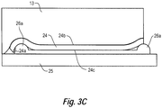
- FIG. 3C is a side view illustrating media, an impression media, a raised support image, and an image forming blanket in cooperation with each other in an image transfer state according to an example. Referring to FIGS.
- an image forming apparatus 100 includes a determination unit 11, a print unit 12, and an image forming blanket 13.
- the image forming apparatus 100 may include a liquid electro photographic (LEP) apparatus, a xerography apparatus, and an inkjet printer.
- LEP liquid electro photographic
- the term LEP may refer to a process of printing in which a liquid toner is applied through an electric field onto a surface forming an electrostatic pattern to form an image. In most LEP processes, the respective image is subsequently transferred to at least one intermediate surface such as an image forming blanket 13, and ultimately to the media 24.
- the determination unit 11 may determine a type of raised support image 26 having a support perimeter p s to be printed on an impression media 25 corresponding to a type of media 24 having a media perimeter p m .
- the determination unit 11 may determine the type of raised support image 26 by at least one of a shape, a size and a thickness of the raised support image 26.
- the size of the raised support image 26 may include a raised support image width r x , a raised support image length r y , and/or a raised support image thickness r z .
- the raised support image 26 may be formed by a multilayer image having an edge profile 26a extending in an outward direction from the impression media 25.
- the edge profile 26a may include at least one of a vertical edge substantially perpendicular to the impression media 25 ( FIG. 4A ), a slanted edge ( FIG. 4B ), and a rounded edge ( FIG. 4C ).
- the raised support image 26 may be in a form of a variety of shapes including an irregular shape.
- the raised support image 26 may have an edge profile including rounded bumps 26a and a central section 26b disposed between the rounded bumps 26a as illustrated in FIG. 3C .
- the rounded bumps 26a may allow the media 24 to create a curved and/or rounded shape for a transition portion of the image forming blanket 13 to conform in the image transfer state and, thus, reducing stressing forces on the image forming blanket 13.
- the central section 26b may be flat and have a uniform thickness. Additionally, an edge portion 24a of the media may be positioned on top of or extend beyond the rounded bump 26a.
- the edge profile of the raised support image 26 may include a position member 26d, a rounded bump 26a, and an end recess 26c disposed between the stop member 26d and the end recess 26c as illustrated in FIG. 3D .
- the rounded bump 26a may allow the edge portion 24a of the media 24 to create a curved and/or rounded shape for a transition portion of the image forming blanket 13 to conform in the image transfer state.
- the end recess 26c may provide space for the edge portion 24a of the media to reside.
- the stop member 26d may support a portion of the edge portion to position the edge portion 24a in the end recess 26c.
- the type of media 24 may include at least one of a size, a thickness m z , and a shape of the media 24.
- the type of the media may correspond to the media's size such as a media width m x and a media height m y .
- the determination unit 11 may be implemented in hardware, software including firmware, or combinations thereof.
- the firmware for example, may be stored in memory and executed by a suitable instruction-execution system.
- the determination unit 11 may be implemented with any or a combination of technologies which are well known in the art (for example, discrete-logic circuits, application-specific integrated circuits (ASICs), programmable-gate arrays (PGAs), field-programmable gate arrays (FPGAs), and/or other later developed technologies.
- the determination unit 11 may be implemented in a combination of software and data executed and stored under the control of a computing device.
- the determination unit 11 may use a lookup table derived from empirical data, a recursive process of measuring deflection and adjusting the raised support image 26, and/or physical properties of the media such as elastic modulus of the media, dimensions and shape of the media, image forming blanket stiffness, the applied forces, and/or image forming blanket structure, and the like.
- the print unit 12 may at least one of print the image to be transferred by the image forming blanket 13 onto the media 24 and print the raised support image 26 determined by the determination unit 11 on the impression media 25 such that the support perimeter p s is smaller than the media perimeter p m .
- the print unit 12 may be configured to both print the image to be transferred by the image forming blanket 13 onto the media and print the raised support image 26 on the impression media 25.
- the image forming apparatus 100 may include a supplemental print unit 52 ( FIG. 5 ). The supplemental print unit 52 may print the raised support image 26 on the impression media 25 and the print unit 12 may print an image to be transferred by the image forming blanket 13 onto the media 24.
- the print unit 12 may apply ink to the PIP to form an image.
- the PIP may transfer the image to the image forming blanket 13.
- the image forming blanket 13 may transfer the image to the media 24.
- the print unit 13 and/or supplemental print unit 52 may include an inkjet print head, a binary ink developer, and the like.
- the ink may include material deposited onto a surface by an image forming apparatus including liquid toners, dry toners, UV cured inks, thermally cured inks, inkjet inks, pigment inks, dye based inks, solutions with colorant, solutions without colorant, solvent based inks, water based inks, plastisols, or other appropriate solutions.
- the image forming blanket 13 may transfer the image to a front surface 24b of the media 24 from the image forming blanket 13 by contacting the media 24 and bending the edge portion 24a of the media 24 about the raised support image 26.
- a portion of a back surface 24c of the media may be supported by the raised support image 26 printed on the impression media 25 such that an edge portion 24a of the media 24 may extend beyond the support perimeter p s .
- the edge portion 24a may not be supported by the raised support image 26.
- space and/or air may be adjacent to the edge portion 24a.
- a portion of the image forming blanket 13 and the edge portion 24a may bend in conformity with each other.
- the image forming blanket 13 may transfer the image to a front surface 24b of the media 24 from the image forming blanket 13 by contacting the media 24 and bending the edge portion 24a of the media 24 about the raised support image 26. Accordingly, the edge portion 24a of the media 24 may create a curved and/or rounded shape for the transition portion of the image forming blanket 13 to conform to in the image transfer state and, thus, reducing stressing forces thereon. Consequently, the formation of edge marks on the image forming blanket 13 and degradation of the image forming blanket 13 may be reduced.
- FIG. 4D is a perspective view illustrating a raised support image and an impression media according to an example.
- a raised support image 36 formed on the impression media 25 may include a media receiving portion 36a and a border portion 36b to surround the media receiving portion 36a.
- the border portion 36b may include a thickness r t substantially equal to a thickness of the media to be received by the media receiving portion 36a.
- an outer perimeter of the border portion 36b may correspond to an outer perimeter of the impression media.25. Accordingly, in operation, the image forming blanket 13 may transfer an image to the media and remain substantially flat upon contact with the media and border portion due to the border portion 36b having a thickness r t substantially equal to the thickness of the media.
- Fig. 5 is a schematic diagram illustrating an image forming apparatus such as an LEP apparatus according to an example.
- the LEP apparatus may include a print unit 12, a supplemental print unit 52, a photo-imaging cylinder 54, a photo charging unit 51, a blanket cylinder 53 including an image forming blanket 13, and an impression cylinder 55.
- the image forming apparatus 100 may form an image on media 24.
- the image may include text, symbols, and/or graphics, and the like.
- the image may be initially formed on the photo-imaging cylinder 54, transferred to the blanket cylinder 53, and then transferred to the media 24.
- an image may be formed on the photo-imaging cylinder 54 by rotating it under the photo charging unit 51.
- the photo charging unit 51 may include a charging device such as corona wire, charge roller, or other charging device and a laser imaging portion.
- a uniform static charge may be deposited on the photo-imaging cylinder 54 by the photo charging unit 51.
- the photo-imaging cylinder 54 continues to rotate, it passes the laser imaging portion of the photo charging unit 51 to dissipate the static charges in selected portions of the image area to leave an electrostatic charge pattern corresponding to the image to be printed.
- ink may be transferred onto the photo-imaging cylinder 54 by a print unit 12.
- the print unit 12 may include a plurality of binary ink developers (BIDs) 12a, 12b, 12c, 12d, 12e, 12f, and 12g.
- BIDs binary ink developers
- a respective BID may correspond to each ink color.
- the appropriate BID may engage with the photo-imaging cylinder 54.
- the engaged BID unit may provide a uniform layer of ink to the photo-imaging cylinder 54.
- the ink may include electrically charged pigment particles attracted to the opposing electrical fields on the image areas of the photo-imaging cylinder 54.
- the ink may be repelled from the uncharged, non-image areas forming a single color ink image on its surface.
- the photo-imaging cylinder 54 may continue to rotate and transfer the ink image to the image forming blanket 13, for example, surrounding the blanket cylinder 53.
- the image forming blanket 13 may transfer the image to the media 24 transported into a nip 57 between the blanket cylinder 53 and the impression cylinder 55. The process may be repeated for each of the colored ink layers to be included in the final image.
- the impression media 25 may be impression paper to receive the raised support image 26.
- the raised support image 26 may be printed on the impression media 25 by the supplemental print unit 52 as illustrated in FIG. 5 .
- the supplemental print unit 52 may include a BID, inkjet printhead, and the like, to provide ink to the impression media 25 to form the raised support image 26 thereon.
- the raised support image 26 may be printed on the impression media 25 by the print unit 12. Subsequently, the impression media 25 and the raised support image 26 thereon are disposed below the media 24. That is, the raised support image 26 contacts and supports a back surface 24c of the media 24 and allows an edge portion 24a of the media 24 to be unsupported by the raised support image 26 in an image transfer state. For example, space and/or air may be adjacent to the edge portion 24a.
- the media 24 and impression media 25 enter the nip 57.
- the image forming blanket 13 contacts the media 25 and transfers the image thereto. That is, the image forming blanket 13 may transfer the image to a front surface 24a of the media 24 from the image forming blanket 13 by contacting the media 24 and bending the edge portion 24a of the media 24 about the raised support image 26. Accordingly, the edge portion 24a of the media 24 may create a curved and/or rounded shape for the transition portion of the image forming blanket 13 to conform to in the image transfer state and, thus, reducing stressing forces thereon. Consequently, the formation of edge marks on the image forming blanket 13 and degradation of the image forming blanket 13 may be reduced.
- one pass of the media 24 through the nip 57 may complete the image.
- the media 24 may be retained to make multiple contacts with the blanket cylinder 53 as it passes through the nip 57.
- the term nip 57 refers to a region between two rollers 53 and 55 where the respective rollers 53 and 55 are in closest proximity to each other.
- an additional color plane may be placed on the media 24.
- all the color planes may be accumulated on the image forming blanket 13 and then transferred at once to the media 24.
- Fig. 6 is a flowchart illustrating a method of transferring an image from an image forming blanket to media according to an example.
- a size of a raised support image having a support perimeter is determined by a determination unit to be printed on an impression media corresponding to a type of media having a media perimeter.
- the size of the raised support image may include at least one of a width, a length, and a thickness.
- the type of media may include at least one of a size of the media, a thickness of the media, and a shape of the media.
- the raised support image determined by the determination unit is printed on the impression media by a print unit such that the support perimeter is smaller than the media perimeter.
- the media perimeter of the media may surround the support perimeter of the raised support image when the raised support image is in contact with the back surface of the media.
- the media perimeter and the support perimeter may be rectangular.
- printing the raised support image may include printing a multilayer image having an edge profile extending outward from the impression media.
- the edge profile may include at least one of a vertical edge substantially perpendicular to the impression media, a slanted edge, and a rounded edge.
- the printing the image to be transferred by an image forming blanket to the media may be performed by the print unit.
- the printing the image to be transferred by an image forming blanket to the media may be performed by a supplemental print unit.
- a portion of a back surface of the media is supported by the raised support image printed on the impression media such that an edge portion of the media extends beyond the support perimeter.
- the image to be transferred by an image forming blanket to the media is printed by the print unit.
- the print unit may apply ink to the PIP to form an image.
- the PIP may transfer the image to the image forming blanket.
- the image forming blanket may transfer the image to the media. That is, in block S618, the image from the image forming blanket is transferred to a front surface of the media by the image forming blanket contacting the media and bending the edge portion of the media about the raised support image.
- the transferring the image from the image forming blanket to a front surface of the media by the image forming blanket may include bending a portion of the image forming blanket and the edge portion of the media in conformity with each other.
- FIG. 7 is a block diagram illustrating a computing device such as an image forming apparatus including a processor and a non-transitory, computer-readable storage medium to store instructions to operate the computing device to transfer an image from an image forming blanket to media according to an example.
- the non-transitory, computer-readable storage medium 77 may be included in a computing device 70 such as an image forming apparatus 100.
- the non-transitory, computer-readable storage medium 77 may be implemented in whole or in part as computer-implemented instructions stored in the image forming apparatus 100 locally or remotely, for example, in a server or a host computing device considered herein to be part of the image forming apparatus 100.
- the non-transitory, computer-readable storage medium 75 may correspond to a storage device that stores instructions 77 such as computer-implemented instructions, programming code, and the like.
- the non-transitory, computer-readable storage medium 75 may include a non-volatile memory, a volatile memory, and/or a storage device.
- non-volatile memory include, but are not limited to, electrically erasable programmable read only memory (EEPROM) and read only memory (ROM).
- Examples of volatile memory include, but are not limited to, static random access memory (SRAM), and dynamic random access memory (DRAM).
- examples of storage devices include, but are not limited to, hard disk drives, compact disc drives, digital versatile disc drives, optical drives, and flash memory devices.
- the non-transitory, computer-readable storage medium 75 may even be paper or another suitable medium upon which the instructions 77 are printed, as the instructions 77 can be electronically captured, via, for instance, optical scanning of the paper or other medium, then compiled, interpreted or otherwise processed in a single manner, if necessary, and then stored therein.
- a processor 79 generally retrieves and executes the instructions 77 stored in the non-transitory, computer-readable storage medium 75, for example, to operate a computing device 70 such as an image forming apparatus 100 to transfer an image from an image forming blanket 13 ( FIG. 1 ) to media 24 in accordance with an example.
- the non-transitory, computer-readable storage medium 75 may be accessed by the processor 79.
- each block may represent a module, segment, or portion of code that includes one or more executable instructions to implement the specified logical function(s).
- each block may represent a circuit or a number of interconnected circuits to implement the specified logical function(s).
- the flowchart of FIG. 6 illustrates a specific order of execution, the order of execution may differ from that which is depicted. For example, the order of execution of two or more blocks may be scrambled relative to the order illustrated. Also, two or more blocks illustrated in succession in FIG. 6 may be executed concurrently or with partial concurrence. All such variations are within the scope of the present disclosure.
Landscapes
- Physics & Mathematics (AREA)
- General Physics & Mathematics (AREA)
- Engineering & Computer Science (AREA)
- Manufacturing & Machinery (AREA)
- Ink Jet (AREA)
- Ink Jet Recording Methods And Recording Media Thereof (AREA)
Claims (14)
- Appareil de formation d'image comprenant un cylindre porte-blanchet (53) comprenant un blanchet de formation d'image (13) ; un cylindre d'impression (55) ;
une unité de détermination (11) permettant de déterminer un type d'image de support en relief (26) ayant un périmètre de support, à imprimer sur un substrat d'impression (25) correspondant à un type de substrat ;
une unité d'impression (12) permettant d'imprimer l'image à transférer par le blanchet de formation d'image (13) sur le substrat (24) et d'imprimer l'image de support en relief sur le substrat d'impression (25),
ou une unité d'impression (12) permettant d'imprimer sur le substrat (24) l'image à transférer par le blanchet de formation d'image (13) et une unité d'impression supplémentaire (52) permettant d'imprimer sur le substrat d'impression (25) l'image de support en relief,
l'image de support en relief (26) étant déterminée par l'unité de détermination (11) comme devant être imprimée sur le substrat d'impression (25), de sorte que le périmètre de support soit inférieur au périmètre de substrat,
le substrat d'impression (25) étant adapté pour recevoir l'image de support en relief (26),
l'appareil étant adapté de sorte que le substrat (24) et le substrat d'impression (25) pénètrent dans une zone de pincement entre le cylindre porte-blanchet (53) et le cylindre d'impression (55), lors de quoi le blanchet de formation d'image (13) transfère l'image sur une surface avant du substrat (24) depuis le blanchet de formation d'image (13) par mise en contact du substrat (24) et pliage de la partie de bord du substrat (24) autour de l'image de support en relief (26). - Appareil de formation d'image selon la revendication 1, dans lequel le type d'image de support en relief (26) comprend une taille de l'image de support en relief (26).
- Appareil de formation d'image selon la revendication 1, dans lequel une partie d'une surface arrière du substrat (24) est soutenue par l'image de support en relief (26) imprimée sur le substrat d'impression (25), de sorte qu'une partie de bord du substrat (24) s'étende au-delà du périmètre de support.
- Procédé de transfert d'une image sur un substrat (24) à partir d'un blanchet de formation d'image (13), le procédé comprenant :la détermination, par une unité de détermination (11), d'une taille d'une image de support en relief (26) ayant un périmètre de support, à imprimer sur un substrat d'impression (25) correspondant à un type de substrat (24) ayant un périmètre de substrat ;l'impression, par une unité d'impression (12) ou une unité d'impression supplémentaire (52), de l'image de support en relief (26) déterminée par l'unité de détermination (11) sur le substrat d'impression (25), de sorte que le périmètre de support soit inférieur au périmètre de substrat, le substrat d'impression (25) reçevant l'image de support en relief (26) ;le soutien, par l'image de support en relief (26) imprimée sur le substrat d'impression (25), d'une partie d'une surface arrière du substrat (24), de sorte qu'une partie de bord du substrat (24) s'étende au-delà du périmètre de support ;l'impression de l'image à transférer par un blanchet de formation d'image (13) sur le substrat (24) ; etle transfert de l'image depuis le blanchet de formation d'image (13) sur une surface avant du substrat (24) par pénétration du substrat (24) et du substrat d'impression (25) dans une zone de pincement entre un cylindre porte-blanchet (53) et un cylindre d'impression (55),et la mise en contact du blanchet de formation d'image (13) et du substrat (24) et le pliage de la partie de bord du substrat (24) autour de l'image de support en relief (26).
- Procédé selon la revendication 4, dans lequel le type de substrat (24) comprend au moins l'une d'une taille du substrat (24), d'une épaisseur du substrat (24) et d'une forme du substrat (24).
- Procédé selon la revendication 4, dans lequel la détermination d'une taille d'une image de support en relief (26) ayant un périmètre de support par une unité de détermination (11) comprend en outre :
la détermination d'au moins l'une d'une largeur, d'une longueur et d'une épaisseur de l'image de support en relief (26). - Procédé selon la revendication 6, dans lequel le périmètre de substrat et le périmètre de support sont rectangulaires.
- Procédé selon la revendication 4, dans lequel l'impression, par l'unité d'impression (12), de l'image de support en relief (26) déterminée par l'unité de détermination (11) sur le substrat d'impression (25) comprend en outre :
l'impression d'une image multicouche ayant un profil de bord s'étendant vers l'extérieur depuis le substrat d'impression (25). - Procédé selon la revendication 8, dans lequel le profil de bord comprend au moins l'un d'un bord vertical sensiblement perpendiculaire au substrat d'impression (25), d'un bord incliné et d'un bord arrondi.
- Procédé selon la revendication 4, dans lequel le périmètre de substrat du substrat entoure le périmètre de support de l'image de support en relief (26) lorsque l'image de support en relief (26) est en contact avec la surface arrière du substrat (24).
- Procédé selon la revendication 4, dans lequel l'impression de l'image à transférer sur le substrat (24) par le blanchet de formation d'image (13) est effectuée par l'unité d'impression (12).
- Procédé selon la revendication 4, dans lequel l'impression de l'image à transférer sur le substrat par le blanchet de formation d'image est effectuée par une unité d'impression supplémentaire.
- Procédé selon la revendication 4, dans lequel le transfert, par le blanchet de formation d'image (13), de l'image depuis le blanchet de formation d'image (13) sur une surface avant du substrat (24) comprend en outre :
le pliage d'une partie du blanchet de formation d'image (13) et de la partie de bord du substrat (24) en conformité l'une avec l'autre. - Support de stockage lisible par ordinateur et non transitoire sur lequel sont stockées des instructions exécutables par ordinateur pour qu'un appareil de formation d'image transfère une image depuis un blanchet de formation d'image (13) sur le substrat (24), les instructions pouvant être exécutées par un processeur (79) pour :déterminer, par une unité de détermination (11), une image de support en relief (26) ayant un périmètre de support à imprimer sur un substrat d'impression (25) correspondant à un type de substrat (24) ;imprimer, par une unité d'impression (12) ou une unité d'impression supplémentaire (52), l'image de support en relief (26) déterminée par l'unité de détermination (11) sur le substrat d'impression (25), le substrat d'impression (25) recevant l'image de support en relief (26) ;soutenir, par l'image de support en relief (26) imprimée sur le substrat d'impression (25), une partie d'une surface arrière du substrat (24) ;imprimer, par l'unité d'impression (12) ou l'unité d'impression supplémentaire (52), l'image à transférer par le blanchet de formation d'image (13) sur le substrat (24) ; ettransférer l'image depuis le blanchet de formation d'image (13) sur une surface avant du substrat (24) par pénétration du substrat (24) et du substrat d'impression (25) dans une zone de pincement entre un cylindre porte-blanchet (53) et un cylindre d'impression (55), et mise en contact du blanchet de formation d'image (13) et du substrat (24).
Applications Claiming Priority (1)
| Application Number | Priority Date | Filing Date | Title |
|---|---|---|---|
| PCT/EP2012/062442 WO2014000783A1 (fr) | 2012-06-27 | 2012-06-27 | Image d'accueil surélevée correspondant au type de support en vue d'accueillir le support |
Publications (2)
| Publication Number | Publication Date |
|---|---|
| EP2867733A1 EP2867733A1 (fr) | 2015-05-06 |
| EP2867733B1 true EP2867733B1 (fr) | 2019-05-22 |
Family
ID=46458491
Family Applications (1)
| Application Number | Title | Priority Date | Filing Date |
|---|---|---|---|
| EP12732614.8A Not-in-force EP2867733B1 (fr) | 2012-06-27 | 2012-06-27 | Image d'accueil surélevée correspondant au type de support en vue d'accueillir le support |
Country Status (3)
| Country | Link |
|---|---|
| US (1) | US20150177667A1 (fr) |
| EP (1) | EP2867733B1 (fr) |
| WO (1) | WO2014000783A1 (fr) |
Families Citing this family (4)
| Publication number | Priority date | Publication date | Assignee | Title |
|---|---|---|---|---|
| CN105056408B (zh) | 2006-06-28 | 2018-09-25 | 美敦力Af卢森堡公司 | 用于热诱导的肾神经调制的系统 |
| TWI620686B (zh) * | 2017-05-19 | 2018-04-11 | 林瑤章 | 推進裝置 |
| TWI620688B (zh) * | 2017-05-19 | 2018-04-11 | 林瑤章 | 輕量飛行載具 |
| JP2024003989A (ja) | 2022-06-28 | 2024-01-16 | 富士フイルムビジネスイノベーション株式会社 | 画像形成装置 |
Family Cites Families (9)
| Publication number | Priority date | Publication date | Assignee | Title |
|---|---|---|---|---|
| US3252410A (en) * | 1963-10-28 | 1966-05-24 | Thomas A Stephenson | Method for producing printed relief impressions on paper |
| JPS6323170A (ja) * | 1986-07-01 | 1988-01-30 | Minolta Camera Co Ltd | 複写機 |
| JP2002023507A (ja) * | 2000-07-06 | 2002-01-23 | Konica Corp | 画像形成装置 |
| US20020048662A1 (en) * | 2000-09-28 | 2002-04-25 | Sca Hygiene Products Gmbh | Method of and apparatus for producing a printed ink pattern on a tissue product, as well as a printed tissue product as such |
| CN100417520C (zh) * | 2003-07-09 | 2008-09-10 | 旭化成化学株式会社 | 无缝印刷用凸版部材的制造方法和制造装置 |
| NL1024767C2 (nl) * | 2003-11-12 | 2005-05-17 | Oce Tech Bv | Werkwijze voor het bedrukken van een ontvangstmateriaal, printer geschikt voor het toepassen van deze werkwijze en werkwijze voor het afstellen van deze printer. |
| US9594529B2 (en) * | 2009-12-17 | 2017-03-14 | Ricoh Company, Ltd. | Methods and apparatus to select a paper source for image printing |
| JP5539581B2 (ja) * | 2010-03-30 | 2014-07-02 | ヒューレット−パッカード デベロップメント カンパニー エル.ピー. | 画像移送ブランケット |
| JP5931180B2 (ja) * | 2011-05-11 | 2016-06-08 | ヒューレット−パッカード・インデイゴ・ビー・ブイHewlett−Packard Indigo B.V. | 印刷浮き出し模様を用いるエンボス加工 |
-
2012
- 2012-06-27 EP EP12732614.8A patent/EP2867733B1/fr not_active Not-in-force
- 2012-06-27 WO PCT/EP2012/062442 patent/WO2014000783A1/fr not_active Ceased
- 2012-06-27 US US14/407,015 patent/US20150177667A1/en not_active Abandoned
Non-Patent Citations (1)
| Title |
|---|
| None * |
Also Published As
| Publication number | Publication date |
|---|---|
| EP2867733A1 (fr) | 2015-05-06 |
| US20150177667A1 (en) | 2015-06-25 |
| WO2014000783A1 (fr) | 2014-01-03 |
Similar Documents
| Publication | Publication Date | Title |
|---|---|---|
| US10889106B2 (en) | Formation of a crease and an image on media | |
| EP2867733B1 (fr) | Image d'accueil surélevée correspondant au type de support en vue d'accueillir le support | |
| CN118119896A (zh) | 打印机和固定图案化板 | |
| US8050614B2 (en) | Hard image forming apparatus and method having contamination removal | |
| IL183220A (en) | Imaging methods, imaging member, charging methods and imaging engines | |
| CN108139705B (zh) | 电子照相打印的方法和电子照相打印机 | |
| JP7500221B2 (ja) | 画像形成装置 | |
| US8577229B2 (en) | Image forming apparatus and method thereof | |
| US10793381B2 (en) | Belt drive for rewritable display medium | |
| CN101257559B (zh) | 控制彩色成像设备的方法 | |
| JP7484518B2 (ja) | 画像形成装置、画像形成方法 | |
| US7970319B2 (en) | Charging apparatus, print engine that incorporates the charging apparatus, and image forming apparatus that incorporates the print engine | |
| CN112534357A (zh) | 减少光电导体表面的反射率变化 | |
| JP6353260B2 (ja) | 画像形成装置 | |
| US10031458B2 (en) | Reduce merging of adjacent printing dots on a photosensitive member | |
| JP2015011088A (ja) | 画像形成装置 | |
| JP2012037769A (ja) | 画像書き換え装置 | |
| JP2003131476A (ja) | 基板を帯電する装置及びこの装置を有する像形成機器 | |
| JP2004341116A (ja) | 接触帯電装置 | |
| JPH09109435A (ja) | 画像記録装置 | |
| JP2002189359A (ja) | 画像形成装置および画像形成方法 | |
| CN104698788A (zh) | 显影装置和成像装置 |
Legal Events
| Date | Code | Title | Description |
|---|---|---|---|
| PUAI | Public reference made under article 153(3) epc to a published international application that has entered the european phase |
Free format text: ORIGINAL CODE: 0009012 |
|
| 17P | Request for examination filed |
Effective date: 20141216 |
|
| AK | Designated contracting states |
Kind code of ref document: A1 Designated state(s): AL AT BE BG CH CY CZ DE DK EE ES FI FR GB GR HR HU IE IS IT LI LT LU LV MC MK MT NL NO PL PT RO RS SE SI SK SM TR |
|
| AX | Request for extension of the european patent |
Extension state: BA ME |
|
| DAX | Request for extension of the european patent (deleted) | ||
| RAP1 | Party data changed (applicant data changed or rights of an application transferred) |
Owner name: HP INDIGO B.V. |
|
| GRAP | Despatch of communication of intention to grant a patent |
Free format text: ORIGINAL CODE: EPIDOSNIGR1 |
|
| STAA | Information on the status of an ep patent application or granted ep patent |
Free format text: STATUS: GRANT OF PATENT IS INTENDED |
|
| INTG | Intention to grant announced |
Effective date: 20190103 |
|
| GRAS | Grant fee paid |
Free format text: ORIGINAL CODE: EPIDOSNIGR3 |
|
| GRAA | (expected) grant |
Free format text: ORIGINAL CODE: 0009210 |
|
| STAA | Information on the status of an ep patent application or granted ep patent |
Free format text: STATUS: THE PATENT HAS BEEN GRANTED |
|
| AK | Designated contracting states |
Kind code of ref document: B1 Designated state(s): AL AT BE BG CH CY CZ DE DK EE ES FI FR GB GR HR HU IE IS IT LI LT LU LV MC MK MT NL NO PL PT RO RS SE SI SK SM TR |
|
| REG | Reference to a national code |
Ref country code: GB Ref legal event code: FG4D |
|
| REG | Reference to a national code |
Ref country code: CH Ref legal event code: EP |
|
| REG | Reference to a national code |
Ref country code: IE Ref legal event code: FG4D |
|
| REG | Reference to a national code |
Ref country code: DE Ref legal event code: R096 Ref document number: 602012060358 Country of ref document: DE |
|
| REG | Reference to a national code |
Ref country code: AT Ref legal event code: REF Ref document number: 1136848 Country of ref document: AT Kind code of ref document: T Effective date: 20190615 |
|
| REG | Reference to a national code |
Ref country code: NL Ref legal event code: MP Effective date: 20190522 |
|
| REG | Reference to a national code |
Ref country code: LT Ref legal event code: MG4D |
|
| PG25 | Lapsed in a contracting state [announced via postgrant information from national office to epo] |
Ref country code: ES Free format text: LAPSE BECAUSE OF FAILURE TO SUBMIT A TRANSLATION OF THE DESCRIPTION OR TO PAY THE FEE WITHIN THE PRESCRIBED TIME-LIMIT Effective date: 20190522 Ref country code: SE Free format text: LAPSE BECAUSE OF FAILURE TO SUBMIT A TRANSLATION OF THE DESCRIPTION OR TO PAY THE FEE WITHIN THE PRESCRIBED TIME-LIMIT Effective date: 20190522 Ref country code: AL Free format text: LAPSE BECAUSE OF FAILURE TO SUBMIT A TRANSLATION OF THE DESCRIPTION OR TO PAY THE FEE WITHIN THE PRESCRIBED TIME-LIMIT Effective date: 20190522 Ref country code: PT Free format text: LAPSE BECAUSE OF FAILURE TO SUBMIT A TRANSLATION OF THE DESCRIPTION OR TO PAY THE FEE WITHIN THE PRESCRIBED TIME-LIMIT Effective date: 20190922 Ref country code: LT Free format text: LAPSE BECAUSE OF FAILURE TO SUBMIT A TRANSLATION OF THE DESCRIPTION OR TO PAY THE FEE WITHIN THE PRESCRIBED TIME-LIMIT Effective date: 20190522 Ref country code: NL Free format text: LAPSE BECAUSE OF FAILURE TO SUBMIT A TRANSLATION OF THE DESCRIPTION OR TO PAY THE FEE WITHIN THE PRESCRIBED TIME-LIMIT Effective date: 20190522 Ref country code: HR Free format text: LAPSE BECAUSE OF FAILURE TO SUBMIT A TRANSLATION OF THE DESCRIPTION OR TO PAY THE FEE WITHIN THE PRESCRIBED TIME-LIMIT Effective date: 20190522 Ref country code: FI Free format text: LAPSE BECAUSE OF FAILURE TO SUBMIT A TRANSLATION OF THE DESCRIPTION OR TO PAY THE FEE WITHIN THE PRESCRIBED TIME-LIMIT Effective date: 20190522 Ref country code: NO Free format text: LAPSE BECAUSE OF FAILURE TO SUBMIT A TRANSLATION OF THE DESCRIPTION OR TO PAY THE FEE WITHIN THE PRESCRIBED TIME-LIMIT Effective date: 20190822 |
|
| PG25 | Lapsed in a contracting state [announced via postgrant information from national office to epo] |
Ref country code: RS Free format text: LAPSE BECAUSE OF FAILURE TO SUBMIT A TRANSLATION OF THE DESCRIPTION OR TO PAY THE FEE WITHIN THE PRESCRIBED TIME-LIMIT Effective date: 20190522 Ref country code: BG Free format text: LAPSE BECAUSE OF FAILURE TO SUBMIT A TRANSLATION OF THE DESCRIPTION OR TO PAY THE FEE WITHIN THE PRESCRIBED TIME-LIMIT Effective date: 20190822 Ref country code: GR Free format text: LAPSE BECAUSE OF FAILURE TO SUBMIT A TRANSLATION OF THE DESCRIPTION OR TO PAY THE FEE WITHIN THE PRESCRIBED TIME-LIMIT Effective date: 20190823 Ref country code: LV Free format text: LAPSE BECAUSE OF FAILURE TO SUBMIT A TRANSLATION OF THE DESCRIPTION OR TO PAY THE FEE WITHIN THE PRESCRIBED TIME-LIMIT Effective date: 20190522 |
|
| REG | Reference to a national code |
Ref country code: AT Ref legal event code: MK05 Ref document number: 1136848 Country of ref document: AT Kind code of ref document: T Effective date: 20190522 |
|
| PG25 | Lapsed in a contracting state [announced via postgrant information from national office to epo] |
Ref country code: DK Free format text: LAPSE BECAUSE OF FAILURE TO SUBMIT A TRANSLATION OF THE DESCRIPTION OR TO PAY THE FEE WITHIN THE PRESCRIBED TIME-LIMIT Effective date: 20190522 Ref country code: SK Free format text: LAPSE BECAUSE OF FAILURE TO SUBMIT A TRANSLATION OF THE DESCRIPTION OR TO PAY THE FEE WITHIN THE PRESCRIBED TIME-LIMIT Effective date: 20190522 Ref country code: RO Free format text: LAPSE BECAUSE OF FAILURE TO SUBMIT A TRANSLATION OF THE DESCRIPTION OR TO PAY THE FEE WITHIN THE PRESCRIBED TIME-LIMIT Effective date: 20190522 Ref country code: CZ Free format text: LAPSE BECAUSE OF FAILURE TO SUBMIT A TRANSLATION OF THE DESCRIPTION OR TO PAY THE FEE WITHIN THE PRESCRIBED TIME-LIMIT Effective date: 20190522 Ref country code: EE Free format text: LAPSE BECAUSE OF FAILURE TO SUBMIT A TRANSLATION OF THE DESCRIPTION OR TO PAY THE FEE WITHIN THE PRESCRIBED TIME-LIMIT Effective date: 20190522 Ref country code: AT Free format text: LAPSE BECAUSE OF FAILURE TO SUBMIT A TRANSLATION OF THE DESCRIPTION OR TO PAY THE FEE WITHIN THE PRESCRIBED TIME-LIMIT Effective date: 20190522 |
|
| REG | Reference to a national code |
Ref country code: CH Ref legal event code: PL |
|
| REG | Reference to a national code |
Ref country code: DE Ref legal event code: R097 Ref document number: 602012060358 Country of ref document: DE |
|
| PG25 | Lapsed in a contracting state [announced via postgrant information from national office to epo] |
Ref country code: MC Free format text: LAPSE BECAUSE OF FAILURE TO SUBMIT A TRANSLATION OF THE DESCRIPTION OR TO PAY THE FEE WITHIN THE PRESCRIBED TIME-LIMIT Effective date: 20190522 Ref country code: IT Free format text: LAPSE BECAUSE OF FAILURE TO SUBMIT A TRANSLATION OF THE DESCRIPTION OR TO PAY THE FEE WITHIN THE PRESCRIBED TIME-LIMIT Effective date: 20190522 Ref country code: SM Free format text: LAPSE BECAUSE OF FAILURE TO SUBMIT A TRANSLATION OF THE DESCRIPTION OR TO PAY THE FEE WITHIN THE PRESCRIBED TIME-LIMIT Effective date: 20190522 |
|
| PLBE | No opposition filed within time limit |
Free format text: ORIGINAL CODE: 0009261 |
|
| REG | Reference to a national code |
Ref country code: BE Ref legal event code: MM Effective date: 20190630 |
|
| STAA | Information on the status of an ep patent application or granted ep patent |
Free format text: STATUS: NO OPPOSITION FILED WITHIN TIME LIMIT |
|
| PG25 | Lapsed in a contracting state [announced via postgrant information from national office to epo] |
Ref country code: TR Free format text: LAPSE BECAUSE OF FAILURE TO SUBMIT A TRANSLATION OF THE DESCRIPTION OR TO PAY THE FEE WITHIN THE PRESCRIBED TIME-LIMIT Effective date: 20190522 |
|
| 26N | No opposition filed |
Effective date: 20200225 |
|
| PG25 | Lapsed in a contracting state [announced via postgrant information from national office to epo] |
Ref country code: IE Free format text: LAPSE BECAUSE OF NON-PAYMENT OF DUE FEES Effective date: 20190627 Ref country code: PL Free format text: LAPSE BECAUSE OF FAILURE TO SUBMIT A TRANSLATION OF THE DESCRIPTION OR TO PAY THE FEE WITHIN THE PRESCRIBED TIME-LIMIT Effective date: 20190522 |
|
| PG25 | Lapsed in a contracting state [announced via postgrant information from national office to epo] |
Ref country code: LI Free format text: LAPSE BECAUSE OF NON-PAYMENT OF DUE FEES Effective date: 20190630 Ref country code: LU Free format text: LAPSE BECAUSE OF NON-PAYMENT OF DUE FEES Effective date: 20190627 Ref country code: CH Free format text: LAPSE BECAUSE OF NON-PAYMENT OF DUE FEES Effective date: 20190630 Ref country code: BE Free format text: LAPSE BECAUSE OF NON-PAYMENT OF DUE FEES Effective date: 20190630 Ref country code: SI Free format text: LAPSE BECAUSE OF FAILURE TO SUBMIT A TRANSLATION OF THE DESCRIPTION OR TO PAY THE FEE WITHIN THE PRESCRIBED TIME-LIMIT Effective date: 20190522 |
|
| PGFP | Annual fee paid to national office [announced via postgrant information from national office to epo] |
Ref country code: FR Payment date: 20200520 Year of fee payment: 9 Ref country code: DE Payment date: 20200519 Year of fee payment: 9 |
|
| PGFP | Annual fee paid to national office [announced via postgrant information from national office to epo] |
Ref country code: GB Payment date: 20200525 Year of fee payment: 9 |
|
| PG25 | Lapsed in a contracting state [announced via postgrant information from national office to epo] |
Ref country code: CY Free format text: LAPSE BECAUSE OF FAILURE TO SUBMIT A TRANSLATION OF THE DESCRIPTION OR TO PAY THE FEE WITHIN THE PRESCRIBED TIME-LIMIT Effective date: 20190522 |
|
| PG25 | Lapsed in a contracting state [announced via postgrant information from national office to epo] |
Ref country code: IS Free format text: LAPSE BECAUSE OF FAILURE TO SUBMIT A TRANSLATION OF THE DESCRIPTION OR TO PAY THE FEE WITHIN THE PRESCRIBED TIME-LIMIT Effective date: 20190922 |
|
| PG25 | Lapsed in a contracting state [announced via postgrant information from national office to epo] |
Ref country code: HU Free format text: LAPSE BECAUSE OF FAILURE TO SUBMIT A TRANSLATION OF THE DESCRIPTION OR TO PAY THE FEE WITHIN THE PRESCRIBED TIME-LIMIT; INVALID AB INITIO Effective date: 20120627 Ref country code: MT Free format text: LAPSE BECAUSE OF FAILURE TO SUBMIT A TRANSLATION OF THE DESCRIPTION OR TO PAY THE FEE WITHIN THE PRESCRIBED TIME-LIMIT Effective date: 20190522 |
|
| REG | Reference to a national code |
Ref country code: DE Ref legal event code: R119 Ref document number: 602012060358 Country of ref document: DE |
|
| GBPC | Gb: european patent ceased through non-payment of renewal fee |
Effective date: 20210627 |
|
| PG25 | Lapsed in a contracting state [announced via postgrant information from national office to epo] |
Ref country code: GB Free format text: LAPSE BECAUSE OF NON-PAYMENT OF DUE FEES Effective date: 20210627 Ref country code: DE Free format text: LAPSE BECAUSE OF NON-PAYMENT OF DUE FEES Effective date: 20220101 |
|
| PG25 | Lapsed in a contracting state [announced via postgrant information from national office to epo] |
Ref country code: FR Free format text: LAPSE BECAUSE OF NON-PAYMENT OF DUE FEES Effective date: 20210630 |
|
| PG25 | Lapsed in a contracting state [announced via postgrant information from national office to epo] |
Ref country code: MK Free format text: LAPSE BECAUSE OF FAILURE TO SUBMIT A TRANSLATION OF THE DESCRIPTION OR TO PAY THE FEE WITHIN THE PRESCRIBED TIME-LIMIT Effective date: 20190522 |