EP2868620A1 - Vorrichtung zur Zugspannungsentlastung einer Hubkette und entsprechende Verfahren - Google Patents
Vorrichtung zur Zugspannungsentlastung einer Hubkette und entsprechende Verfahren Download PDFInfo
- Publication number
- EP2868620A1 EP2868620A1 EP14191438.2A EP14191438A EP2868620A1 EP 2868620 A1 EP2868620 A1 EP 2868620A1 EP 14191438 A EP14191438 A EP 14191438A EP 2868620 A1 EP2868620 A1 EP 2868620A1
- Authority
- EP
- European Patent Office
- Prior art keywords
- mast
- lift
- stage
- attachment
- hanger
- Prior art date
- Legal status (The legal status is an assumption and is not a legal conclusion. Google has not performed a legal analysis and makes no representation as to the accuracy of the status listed.)
- Granted
Links
Images




Classifications
-
- B—PERFORMING OPERATIONS; TRANSPORTING
- B66—HOISTING; LIFTING; HAULING
- B66F—HOISTING, LIFTING, HAULING OR PUSHING, NOT OTHERWISE PROVIDED FOR, e.g. DEVICES WHICH APPLY A LIFTING OR PUSHING FORCE DIRECTLY TO THE SURFACE OF A LOAD
- B66F9/00—Devices for lifting or lowering bulky or heavy goods for loading or unloading purposes
- B66F9/06—Devices for lifting or lowering bulky or heavy goods for loading or unloading purposes movable, with their loads, on wheels or the like, e.g. fork-lift trucks
- B66F9/075—Constructional features or details
- B66F9/20—Means for actuating or controlling masts, platforms, or forks
-
- B—PERFORMING OPERATIONS; TRANSPORTING
- B66—HOISTING; LIFTING; HAULING
- B66F—HOISTING, LIFTING, HAULING OR PUSHING, NOT OTHERWISE PROVIDED FOR, e.g. DEVICES WHICH APPLY A LIFTING OR PUSHING FORCE DIRECTLY TO THE SURFACE OF A LOAD
- B66F9/00—Devices for lifting or lowering bulky or heavy goods for loading or unloading purposes
- B66F9/06—Devices for lifting or lowering bulky or heavy goods for loading or unloading purposes movable, with their loads, on wheels or the like, e.g. fork-lift trucks
- B66F9/075—Constructional features or details
- B66F9/07504—Accessories, e.g. for towing, charging, locking
-
- B—PERFORMING OPERATIONS; TRANSPORTING
- B66—HOISTING; LIFTING; HAULING
- B66F—HOISTING, LIFTING, HAULING OR PUSHING, NOT OTHERWISE PROVIDED FOR, e.g. DEVICES WHICH APPLY A LIFTING OR PUSHING FORCE DIRECTLY TO THE SURFACE OF A LOAD
- B66F9/00—Devices for lifting or lowering bulky or heavy goods for loading or unloading purposes
- B66F9/06—Devices for lifting or lowering bulky or heavy goods for loading or unloading purposes movable, with their loads, on wheels or the like, e.g. fork-lift trucks
- B66F9/075—Constructional features or details
- B66F9/07509—Braking
-
- B—PERFORMING OPERATIONS; TRANSPORTING
- B66—HOISTING; LIFTING; HAULING
- B66F—HOISTING, LIFTING, HAULING OR PUSHING, NOT OTHERWISE PROVIDED FOR, e.g. DEVICES WHICH APPLY A LIFTING OR PUSHING FORCE DIRECTLY TO THE SURFACE OF A LOAD
- B66F9/00—Devices for lifting or lowering bulky or heavy goods for loading or unloading purposes
- B66F9/06—Devices for lifting or lowering bulky or heavy goods for loading or unloading purposes movable, with their loads, on wheels or the like, e.g. fork-lift trucks
- B66F9/075—Constructional features or details
- B66F9/08—Masts; Guides; Chains
Definitions
- the field of the present disclosure relates to accessories for lift truck masts.
- lift chains on certain lift truck masts are typically under constant, or nearly constant, tension. For example, when the mast is not fully lowered with an attachment resting on the ground the lift chains are under constant tension. For some lift trucks in certain applications, such as empty container handling, the lift chains rarely, if ever, are relieved from being tensioned. Some lift truck lift chains therefore carry a relatively large proportion of the rated load for a lift truck, even when not lifting a load, because of the construction, kinematics, dimensions, and weight of attachments secured to the mast.
- the present inventors have also recognized that maintaining lift chains under constant, or nearly constant, tension inhibits effective lubrication of such chains.
- the present inventors have also recognized that maintaining lift chains under constant, or nearly constant, tension typically reduces lift chain life.
- the present inventors created devices and methods to relieve lift chains from being maintained under constant, or nearly constant, tension.
- a device for facilitating lift chain tension relief is illustrated in Figs. 1-3 .
- a mast-hanger 10 includes a first support 15 and a second support 20 that are connected by an optional spacer 25.
- Each of the first support 15 and the second support 20 include a mast receiving formation 30, an attachment receiving formation 35, and an optional mast attachment 40.
- the mast receiving formation 30 comprises a raised portion 31 and a lip 32 that forms a pocket 33.
- the attachment receiving portion 35 comprises a sloped shelf 36.
- the mast attachment 40 comprises a hook-shape.
- each of the first support 15 and the second support 20 are integrally formed with a mast receiving formation 30, an attachment receiving formation 35, and a mast attachment 40, for example, by casting, forging, cutting, or stamping using ductile iron, steel, or other suitable material.
- the first support 15 and the second support 20 may be formed by providing an elongate bar and securing one or more of a mast receiving formation 30, an attachment receiving formation 35, and a mast attachment 40 to each elongate bar by welding, bolting or other suitable attachment.
- a mast hanger 10A includes only a mast receiving formation 30A ( Fig. 1A ).
- a mast hanger 10B includes only an attachment receiving formation 35b ( Fig. 1B ).
- the optional spacer 25 is preferably secured to each of the first support 15 and the second support 20 via bolts, welds, or other suitable attachment.
- the spacer 25 may be constructed from a relatively lightweight material such as sheet metal or a rigid plastic.
- the optional spacer 25 facilitates maintaining the first support 15 and the second support 20 in contact with cross members 55 and 60 by engaging a back-side of the cross member 55.
- the mast-hanger 10 may be bolted, welded, or otherwise suitably secured in place.
- one or both of the optional spacer 25 and mast attachment 40 may be omitted.
- the optional spacer 25 maybe omitted even if the mast-hanger 10 is not bolted, welded or otherwise fastened to the two stage mast 45.
- Fig. 3 illustrates the mast-hanger 10 of Fig. 1 supporting the second stage 65 of the two stage mast 45 and an attachment 70.
- some attachments do not permit a lift truck operator to fully lower the attachment to the ground, thus removing some or all of the tension in the lift chains.
- attachments designed to handle empty cargo containers typically cannot be set on the ground and thus do not permit a lift truck operator to fully lower such attachments.
- Pocket 33 is shaped and sized to receive the second stage 65 of the two stage mast and thus transfer some or all of the weight of the second stage 65 from the lift chains to the cross member 55.
- Sloped shelf 36 is shaped and sized to receive the attachment 70 and thus transfer some or all of the weight of the attachment 70 from the lift chains to the cross member 55.
- the attachment 70 includes an integrated carriage. However, some carriages are not integrated with an attachment, and in certain embodiments the sloped shelf 36, or another suitable portion of a mast-hanger, is preferably shaped and sized to receive such a non-integrated carriage, a non-integrated attachment, or both.
- An attachment receiving portion is therefore a portion of a mast-hanger that is (1) sized and shaped to receive an integrated carriage and attachment, (2) sized and shaped to receive a non-integrated carriage, (3) sized and shaped to receive a non-integrated attachment, or (4) sized and shaped to receive a non-integrated carriage and a non-integrated attachment.
- the two stage mast 45 is oriented in a substantially vertical position to facilitate transferring some or all of the weight of the second stage 65 and of the attachment 70 to the cross member 55.
- mast-hanger such as mast-hanger 10
- a lift truck equipped with an attachment that does not permit the operator to fully lower the attachment to the ground
- such mast-hanger provides a location at which the mast, the carriage, the attachment, or any combination thereof, including all three, may be placed to remove all, substantially all, or a portion of the tension from the lift chains.
- lift chains may have an extended life compared to lift chains of an equivalent lift truck equipped with the same attachment, but without a mast-hanger.
- lift chain life may be extended because the relaxed tension may permit lubrication oil to flow into the links better than if such tension were not removed from the lift chains.
- lift chain life may be extended because relaxing or removing tensions from such lift chains reduces internal stresses within such lift chains.
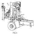
- the mast-hanger 100 includes two supports comprising a first beam 115 and a second beam 120 that are supported by a first stage 146 of a multi-stage mast 145.
- the multi-stage mast 145 is a two-stage mast, however more than two stages may be included, or the mast may not be a multi-stage mast and only one stage may be included.
- Beams 115 and 120 are supported by beam supports 125 and 130, respectively, such that beams 115 and 120 are moveable with respect to the first stage of the multi-stage mast 145.
- beams 115 and 120 slide with respect to beam supports 125 and 130, however beams 115 and 120 may rotate or pivot with respect to beam supports 125 and 130, or may otherwise be suitably configured for movement with respect to the first stage 146 of the multi-stage mast 145.
- Beams 115 and 120 may be manually moveable, or may be moveable via an automated device, such as hydraulic extension cylinders 135, an electric linear actuator, an electric motor, or other suitable motive source.
- an automated device such as hydraulic extension cylinders 135, an electric linear actuator, an electric motor, or other suitable motive source.
- Two supports are illustrated, but some embodiments include only one support and other embodiments include three or four supports.
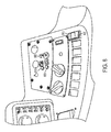
- Mast hanger 100 optionally includes one or more signal devices, such as lights 805 and 815 ( Fig. 8 ).
- a signal device may be mounted on a portion of a lift truck such as an operator compartment, or other suitable location where the signal device may be readily viewed by the lift truck operator.
- the signal device may include a hand-held electronic device that wirelessly communicates with a mast hanger and provides operational information regarding the mast hanger via a screen, such as by displaying printed information or graphic information.
- the signal device communicates with the mast hanger, such as mast hanger 100, and is configured to provide information regarding the operational status of the mast hanger to someone viewing the signal device.
- the mast hanger 100 is associated with one or more position sensors, such as optical sensors, an encoder associated with the motive source, one or more Hall-effect sensors and one or more magnets, or other suitable position sensor for providing a signal indicative of the position of the beams 115 and 120.
- One signal indicates that the beams 115 and 120 are in a fully retracted, or non-mast receiving, position (illustrated in Fig. 4 ) where the beams 115 and 120 do not interfere with lowering the second stage 155 of the mast 145.
- Another signal indicates that the beams 115 and 120 are in a fully extended, or mast receiving, position (illustrated in Fig. 5 ) where the beams 115 and 120 inhibit lowering the second stage 155 of the mast 145.
- Additional sensors that detect the position of the mast 145, an attachment connected to the mast, or both optionally communicate with the signal device.
- the signal device may indicate to the operator when a mast hanger receives the mast 145, an attachment, or both and provide a signal to inform the operator that the mast 145 should not be lowered any further.
- an indication that a mast hanger receives the mast 145, an attachment, or both may be communicated to a processor on-board a lift truck and the processor may inhibit or prevent the operator from further lowering the mast 145, an attachment, or both.
- Inhibiting or preventing further lowering of the mast 145, an attachment, or both once received by a mast hanger may prevent the lift chains from becoming excessively slack which may cause the lift chains to become damaged or move out of alignment, or may cause unwanted stress from a sudden impact on the chains when the mast 145, an attachment, or both are lifted from the mast hanger.
- a strain gauge or other suitable weight bearing determination device may be associated with the beams 115 and 120 to provide an additional signal that the beams 115 and 120 are bearing at least a portion of the weight of the second stage 155 of the mast 145 and of any attachment and load connected to the mast 145.
- an illuminated light or other suitable indicator that indicates that the beams 115 and 120 are at the fully extended position may only be illuminated if the beams 115 and 120 are at the fully extended position and are bearing weight, or there may be one indicator, such as an illuminated light, that indicates that the beams 115 and 120 are at the fully extended position and another indicator, such as an illuminated light, that indicates that the beams 115 and 120 are bearing weight.
- a shock absorber such as an impact pad, damper or other suitable device for absorbing some of the shock resulting from contacting the mast 145, an attachment, or both with the beams 115 and 120 may be included.
- a shock absorber 122 ( Fig. 4 ) may be provided on a top surface of beams 115 and 120.
- Shock absorber 122 may be a pad of resilient material, such as natural rubber, soft plastic, or other suitable material, that is affixed to the beams 115 and 120; or shock absorber 122 may include dampening devices such as springs, resilient absorbers or other suitable devices interposed between a contact plate and the beam 115 or 120.
- a shock absorber 122, or other suitable device may be located on the top side of pocket 33, sloped shelf 36, or both ( Fig. 1 ).
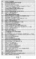
- Fig. 6 illustrates a flowchart for a method of facilitating lift chain tension relief.
- a lift truck operator raises a second stage of a multi-stage mast and an attachment above the position of a mast-hanger to an initial position.
- an initial position may be any position above pockets 33 ( Fig. 1 ) or the beams 115 and 120 ( Fig. 4 ), but is preferably a position that is 5 cm to cm above the pockets 33 or the beams 115 and 120.
- Optional step 605 involves moving the mast-hanger into a mast receiving position. Step 605 is optional for mast-hangers that may be maintained in a mast receiving position such as mast-hanger 10, for example.
- the lift truck operator lowers at least the second stage of a multi-stage mast and optionally an attachment onto the mast hanger.
- the lift truck operator continues to apply a lower command to the mast to relieve at least some of the tension from the lift chains as the weight of the attachment and at least the second stage of the multi-stage mast are transferred to the first stage of the multi-stage mast via the mast-hanger. In other words, the attachment does not contact the ground at step 615.
- an exemplary process for operating a mast hanger that includes beams 115 and 120 is described.
- an operator activates the park brake at step 700.
- the operator manipulates key switch 800 to the "on" position to activate the mast hanger system at step 705.
- a processor associated with the mast hanger system detects the activation of the park brake, and switches blue light 805 on at step 710 to indicate that the mast hanger system is active. If the processor does not detect that the park brake has been activated, the mast hanger system may prompt the operator to activate the park brake, for example, by flashing blue light 805. Preferably, any time there is an error with operation of the mast hanger system detected by the processor, the blue light 805 is flashed.
- the processor activates a park brake lock at step 715 to prevent disengagement of the park brake while the mast hanger system is active.
- the operator moves an attachment connected to the mast 145 into an initial position, for example, the operator may move a spreader for moving cargo containers to a position that is in the range of 5 cm to cm above the beams 115 and 120, and preferably approximately 12 cm, and at step 725 the processor detects when the attachment is in an initial position by receiving input from a proximity switch or other suitable sensor positioned and configured to send a signal when the attachment is in the initial position.
- the processor determines whether the beams 115 and 120 are at the retracted position, for example, via signals sent from a proximity switch, Hall effect sensor, or other suitable sensor, and if not, activates a reduced lowering speed function that limits the speed at which an attachment may be lowered.
- the processor determines whether the beams 115 and 120 are at their extended positions, for example, via signals sent from a proximity switch, Hall effect sensor, or other suitable sensor, and if so, disables the extend switch 810 and deactivates the lowering interrupt function.
- the operator lowers the attachment until the attachment, the mast 145, or both, contact the beams 115 and 120.
- the processor may automatically activate a reduced lowering speed, deactivate the lowering interrupt function, and lower the attachment until the attachment, the mast 145, or both, contact the beams 115 and 120 in response to determining that the beams 115 and 120 are at their extended positions, or in response to another suitable signal.
- step 755 Contact of the attachment, the mast 145, or both, with the beams 115 and 120 is detected at step 755, for example, via signals sent from a proximity switch, strain gauge, or other suitable sensor, and the processor activates the lowering interrupt function and an indicator, such as green light 815, to indicate to the operator that the attachment, the mast 145, or both are in position on the beams 115 and 120.
- the processor also deactivates the retract switch 820.
- the processor may lift the attachment, the mast 145, or both from the beams 115 and 120, detect that the attachment, the mast 145, or both are no longer supported by the beams 115 and 120, disable the lowering interrupt function, turn the green light 815 off, and move the beams 115 and 120 to their retracted positions in response to receiving a signal from the retract switch 820, or from another suitable signal source.
- the processor detects whether the beams 115 and 120 are at their extended positions, for example, via signals sent from a proximity switch, hall effect sensor, or other suitable sensor, and if not, enables the extend switch 810 and the lowering interrupt function.
- the processor detects whether the beams 115 and 120 are at their retracted positions, for example, via signals sent from a proximity switch, hall effect sensor, or other suitable sensor, and if so, deactivates the reduced lowering speed function, deactivates the lowering interrupt function, enables the extend switch 810, preferably only if the attachment, the mast 145, or both are in an initial position above the beams 115 and 120, and disables the retract switch 820.
- the operator deactivates the mast hanger system at step 785 by manipulating the key switch 800 to the off position.
- the processor deactivates the blue light 805 to indicate to the operator that the mast hanger system is deactivated and deactivates the park brake lock.
Landscapes
- Engineering & Computer Science (AREA)
- Transportation (AREA)
- Structural Engineering (AREA)
- Civil Engineering (AREA)
- Life Sciences & Earth Sciences (AREA)
- Geology (AREA)
- Mechanical Engineering (AREA)
- Chemical & Material Sciences (AREA)
- Combustion & Propulsion (AREA)
- Forklifts And Lifting Vehicles (AREA)
- Lift-Guide Devices, And Elevator Ropes And Cables (AREA)
Priority Applications (1)
| Application Number | Priority Date | Filing Date | Title |
|---|---|---|---|
| EP21158026.1A EP3868701B1 (de) | 2013-11-05 | 2014-11-03 | Vorrichtung zur zugspannungsentlastung einer hubkette und entsprechende verfahren |
Applications Claiming Priority (1)
| Application Number | Priority Date | Filing Date | Title |
|---|---|---|---|
| US201361900015P | 2013-11-05 | 2013-11-05 |
Related Child Applications (1)
| Application Number | Title | Priority Date | Filing Date |
|---|---|---|---|
| EP21158026.1A Division EP3868701B1 (de) | 2013-11-05 | 2014-11-03 | Vorrichtung zur zugspannungsentlastung einer hubkette und entsprechende verfahren |
Publications (2)
| Publication Number | Publication Date |
|---|---|
| EP2868620A1 true EP2868620A1 (de) | 2015-05-06 |
| EP2868620B1 EP2868620B1 (de) | 2021-03-10 |
Family
ID=51862156
Family Applications (2)
| Application Number | Title | Priority Date | Filing Date |
|---|---|---|---|
| EP21158026.1A Active EP3868701B1 (de) | 2013-11-05 | 2014-11-03 | Vorrichtung zur zugspannungsentlastung einer hubkette und entsprechende verfahren |
| EP14191438.2A Active EP2868620B1 (de) | 2013-11-05 | 2014-11-03 | Vorrichtung zur Zugspannungsentlastung einer Hubkette und entsprechende Verfahren |
Family Applications Before (1)
| Application Number | Title | Priority Date | Filing Date |
|---|---|---|---|
| EP21158026.1A Active EP3868701B1 (de) | 2013-11-05 | 2014-11-03 | Vorrichtung zur zugspannungsentlastung einer hubkette und entsprechende verfahren |
Country Status (4)
| Country | Link |
|---|---|
| US (2) | US10329130B2 (de) |
| EP (2) | EP3868701B1 (de) |
| CN (2) | CN107032264B (de) |
| AU (1) | AU2014256368B2 (de) |
Cited By (1)
| Publication number | Priority date | Publication date | Assignee | Title |
|---|---|---|---|---|
| CN109231032A (zh) * | 2018-10-15 | 2019-01-18 | 周宁县善长祥农业机械研发有限公司 | 一种农业吊机 |
Families Citing this family (3)
| Publication number | Priority date | Publication date | Assignee | Title |
|---|---|---|---|---|
| EP3315455B1 (de) * | 2016-10-28 | 2019-11-27 | Hyster-Yale Group, Inc. | Mastunterstützungsvorrichtung |
| US11565923B2 (en) | 2019-02-19 | 2023-01-31 | Crown Equipment Corporation | Chain slack detection system |
| US12600609B2 (en) | 2024-06-20 | 2026-04-14 | Mitsubishi Logisnext Americas Inc. | Hose supports for facilitating the assembly of masts for material handling vehicles and related methods |
Citations (6)
| Publication number | Priority date | Publication date | Assignee | Title |
|---|---|---|---|---|
| GB870361A (en) * | 1959-03-09 | 1961-06-14 | Multi Lift Co | Load hoisting mast |
| GB1402307A (en) * | 1971-08-26 | 1975-08-06 | Welch F D | Materials handling apparatus for attachment to a crane |
| US4307792A (en) * | 1980-03-18 | 1981-12-29 | J. I. Case Company | Forklift roller mast lock |
| JPS6186394U (de) * | 1984-11-09 | 1986-06-06 | ||
| JPS62144296U (de) * | 1986-02-28 | 1987-09-11 | ||
| JPH0346999A (ja) * | 1989-07-13 | 1991-02-28 | Toyota Autom Loom Works Ltd | フォークリフトの荷役装置 |
Family Cites Families (25)
| Publication number | Priority date | Publication date | Assignee | Title |
|---|---|---|---|---|
| US1402307A (en) * | 1920-10-07 | 1922-01-03 | Eloise H Metcalf | Closet attachment |
| US2456320A (en) * | 1947-02-24 | 1948-12-14 | Ross Carrier Company | Lift truck |
| US2581791A (en) * | 1949-06-18 | 1952-01-08 | Shepard Co Lewis | Industrial lift truck |
| US3786902A (en) * | 1972-05-08 | 1974-01-22 | Knickerbocker Co | Load-lifting mechanism for a lift truck |
| US3851732A (en) * | 1973-02-08 | 1974-12-03 | Towmotor Corp | Mast and carriage for a lift truck |
| US3974927A (en) * | 1974-07-15 | 1976-08-17 | Little Giant Products, Inc. | Side shifter assembly for lift trucks |
| US4034855A (en) * | 1975-09-25 | 1977-07-12 | Caterpillar Tractor Co. | Suspended guide rollers |
| US4030568A (en) * | 1976-03-24 | 1977-06-21 | Caterpillar Tractor Co. | High visibility mast for lift trucks |
| US4544323A (en) * | 1982-09-03 | 1985-10-01 | Malin James I | Quick coupling and lift device |
| US4896748A (en) * | 1988-05-27 | 1990-01-30 | Caterpillar Industrial Inc. | Full free lift mast assembly |
| US4921075A (en) * | 1989-02-21 | 1990-05-01 | Teledyne Princeton, Inc. | Fork lift |
| DE19855202B4 (de) * | 1997-12-01 | 2006-10-26 | Nissan Motor Co., Ltd., Yokohama | Mastanordnung und mit einem Mast ausgerüsteter Hubwagen |
| ATE522470T1 (de) * | 2003-05-30 | 2011-09-15 | Moffett Res & Dev Ltd | Gabelhubwagen mit einem freihubbewegungsmast montiert auf einem lastkraftwagen |
| JP2004359406A (ja) * | 2003-06-04 | 2004-12-24 | Toyota Industries Corp | フォークリフトのマスト構造およびその製造方法 |
| JP4806985B2 (ja) | 2005-07-15 | 2011-11-02 | 株式会社豊田自動織機 | 産業車両のリフト装置 |
| CN100575239C (zh) | 2007-06-14 | 2009-12-30 | 王树生 | 轮对堆垛机 |
| DE102008035583B4 (de) | 2008-07-30 | 2024-09-12 | Liebherr-Werk Ehingen Gmbh | Teleskopausleger eines Krans und Verfahren zu seiner Abspannung |
| CN201485228U (zh) | 2009-08-31 | 2010-05-26 | 晋正自动化工程(浙江)有限公司 | 船型桶堆叠机 |
| CN201512390U (zh) * | 2009-09-10 | 2010-06-23 | 浙江杭叉工程机械集团股份有限公司 | 一种双层滚动电动叉车 |
| US8777545B2 (en) * | 2009-10-20 | 2014-07-15 | Bright Coop, Inc. | Free lift mast for truck mounted forklift |
| CN101913546B (zh) * | 2010-07-26 | 2012-12-26 | 三峡大学 | 车用cng气瓶装卸和搬运装置及装卸方法 |
| CN201777852U (zh) * | 2010-08-15 | 2011-03-30 | 芜湖瑞创叉车有限公司 | 一种叉车工作装置 |
| CN202575884U (zh) * | 2012-04-17 | 2012-12-05 | 安徽合力股份有限公司 | 具有防冲击链条的叉车门架总成 |
| CN202785500U (zh) * | 2012-08-15 | 2013-03-13 | 新疆众和股份有限公司 | 电极箔成品箔卷的收取和运送装置 |
| CN103232011B (zh) * | 2013-05-16 | 2015-12-09 | 烽火通信科技股份有限公司 | 一种光缆金属带搬运车 |
-
2014
- 2014-10-29 US US14/527,531 patent/US10329130B2/en active Active
- 2014-10-30 AU AU2014256368A patent/AU2014256368B2/en active Active
- 2014-11-03 EP EP21158026.1A patent/EP3868701B1/de active Active
- 2014-11-03 EP EP14191438.2A patent/EP2868620B1/de active Active
- 2014-11-05 CN CN201710184140.2A patent/CN107032264B/zh active Active
- 2014-11-05 CN CN201410783805.8A patent/CN104787689B/zh active Active
-
2019
- 2019-05-13 US US16/410,841 patent/US10773937B2/en active Active
Patent Citations (6)
| Publication number | Priority date | Publication date | Assignee | Title |
|---|---|---|---|---|
| GB870361A (en) * | 1959-03-09 | 1961-06-14 | Multi Lift Co | Load hoisting mast |
| GB1402307A (en) * | 1971-08-26 | 1975-08-06 | Welch F D | Materials handling apparatus for attachment to a crane |
| US4307792A (en) * | 1980-03-18 | 1981-12-29 | J. I. Case Company | Forklift roller mast lock |
| JPS6186394U (de) * | 1984-11-09 | 1986-06-06 | ||
| JPS62144296U (de) * | 1986-02-28 | 1987-09-11 | ||
| JPH0346999A (ja) * | 1989-07-13 | 1991-02-28 | Toyota Autom Loom Works Ltd | フォークリフトの荷役装置 |
Cited By (1)
| Publication number | Priority date | Publication date | Assignee | Title |
|---|---|---|---|---|
| CN109231032A (zh) * | 2018-10-15 | 2019-01-18 | 周宁县善长祥农业机械研发有限公司 | 一种农业吊机 |
Also Published As
| Publication number | Publication date |
|---|---|
| EP3868701A1 (de) | 2021-08-25 |
| CN104787689B (zh) | 2017-03-22 |
| US20150122585A1 (en) | 2015-05-07 |
| CN107032264B (zh) | 2019-11-12 |
| EP2868620B1 (de) | 2021-03-10 |
| CN107032264A (zh) | 2017-08-11 |
| CN104787689A (zh) | 2015-07-22 |
| AU2014256368A1 (en) | 2015-05-21 |
| US20190263647A1 (en) | 2019-08-29 |
| US10773937B2 (en) | 2020-09-15 |
| EP3868701B1 (de) | 2022-10-05 |
| AU2014256368B2 (en) | 2019-04-04 |
| US10329130B2 (en) | 2019-06-25 |
Similar Documents
| Publication | Publication Date | Title |
|---|---|---|
| US10773937B2 (en) | Lift chain tension relieving devices and methods | |
| US20110150613A1 (en) | Integrated Boom/Underlift Assembly and Support Device | |
| KR101507626B1 (ko) | 지게차의 안전작업을 위한 카메라 장치 | |
| CN101670805A (zh) | 超大起升能力的随车起重运输车 | |
| GB2440676A (en) | Restraint for fork-lift truck | |
| CN204151024U (zh) | 一种叉车起升油缸固定机构 | |
| US20100213754A1 (en) | Support Systems for a Truck | |
| CN202575884U (zh) | 具有防冲击链条的叉车门架总成 | |
| JP2002178956A (ja) | 大型運搬車両 | |
| CN202106812U (zh) | 一种重型轮胎拆装车 | |
| JPS63277194A (ja) | カウンタ−バランスクレ−ンのバランスウエイト作動装置 | |
| CA2960065C (en) | Crane for lifting and transporting loads comprising a roll-over protection system | |
| CN221027568U (zh) | 一种电动叉车起升门架坠落检测装置 | |
| CN104925147A (zh) | 驾驶室翻转限位装置 | |
| CA2960061C (en) | Crane for lifting and transporting loads | |
| KR20160040756A (ko) | 트럭 탑재용 덤프장치 | |
| CN202130999U (zh) | 滑移装载机起吊装置 | |
| CN202686079U (zh) | 一种挂车载货平台升降装置 | |
| CN108046174A (zh) | 一种可转向智能升降叉车 | |
| CN120504277A (zh) | 一种便于维护的高位拣选车 | |
| US9505332B2 (en) | Vehicle recovery tool | |
| KR200258376Y1 (ko) | 크롤라식 트랙을 장착한 지게차 | |
| JP2016190538A (ja) | 軌陸車の転車台操作規制装置 | |
| KR19990008973U (ko) | 래크와 피니언을 이용한 지게차용 사이드 쉬프트장치 | |
| CN109592570A (zh) | 一种重型起吊车辆 |
Legal Events
| Date | Code | Title | Description |
|---|---|---|---|
| PUAI | Public reference made under article 153(3) epc to a published international application that has entered the european phase |
Free format text: ORIGINAL CODE: 0009012 |
|
| 17P | Request for examination filed |
Effective date: 20141103 |
|
| AK | Designated contracting states |
Kind code of ref document: A1 Designated state(s): AL AT BE BG CH CY CZ DE DK EE ES FI FR GB GR HR HU IE IS IT LI LT LU LV MC MK MT NL NO PL PT RO RS SE SI SK SM TR |
|
| AX | Request for extension of the european patent |
Extension state: BA ME |
|
| R17P | Request for examination filed (corrected) |
Effective date: 20151029 |
|
| RBV | Designated contracting states (corrected) |
Designated state(s): AL AT BE BG CH CY CZ DE DK EE ES FI FR GB GR HR HU IE IS IT LI LT LU LV MC MK MT NL NO PL PT RO RS SE SI SK SM TR |
|
| RAP1 | Party data changed (applicant data changed or rights of an application transferred) |
Owner name: HYSTER-YALE GROUP, INC. |
|
| STAA | Information on the status of an ep patent application or granted ep patent |
Free format text: STATUS: EXAMINATION IS IN PROGRESS |
|
| 17Q | First examination report despatched |
Effective date: 20180530 |
|
| GRAP | Despatch of communication of intention to grant a patent |
Free format text: ORIGINAL CODE: EPIDOSNIGR1 |
|
| STAA | Information on the status of an ep patent application or granted ep patent |
Free format text: STATUS: GRANT OF PATENT IS INTENDED |
|
| INTG | Intention to grant announced |
Effective date: 20200918 |
|
| GRAS | Grant fee paid |
Free format text: ORIGINAL CODE: EPIDOSNIGR3 |
|
| GRAA | (expected) grant |
Free format text: ORIGINAL CODE: 0009210 |
|
| STAA | Information on the status of an ep patent application or granted ep patent |
Free format text: STATUS: THE PATENT HAS BEEN GRANTED |
|
| AK | Designated contracting states |
Kind code of ref document: B1 Designated state(s): AL AT BE BG CH CY CZ DE DK EE ES FI FR GB GR HR HU IE IS IT LI LT LU LV MC MK MT NL NO PL PT RO RS SE SI SK SM TR |
|
| REG | Reference to a national code |
Ref country code: GB Ref legal event code: FG4D |
|
| REG | Reference to a national code |
Ref country code: AT Ref legal event code: REF Ref document number: 1369632 Country of ref document: AT Kind code of ref document: T Effective date: 20210315 Ref country code: CH Ref legal event code: EP |
|
| REG | Reference to a national code |
Ref country code: DE Ref legal event code: R096 Ref document number: 602014075512 Country of ref document: DE |
|
| REG | Reference to a national code |
Ref country code: IE Ref legal event code: FG4D |
|
| REG | Reference to a national code |
Ref country code: LT Ref legal event code: MG9D |
|
| PG25 | Lapsed in a contracting state [announced via postgrant information from national office to epo] |
Ref country code: NO Free format text: LAPSE BECAUSE OF FAILURE TO SUBMIT A TRANSLATION OF THE DESCRIPTION OR TO PAY THE FEE WITHIN THE PRESCRIBED TIME-LIMIT Effective date: 20210610 Ref country code: BG Free format text: LAPSE BECAUSE OF FAILURE TO SUBMIT A TRANSLATION OF THE DESCRIPTION OR TO PAY THE FEE WITHIN THE PRESCRIBED TIME-LIMIT Effective date: 20210610 Ref country code: HR Free format text: LAPSE BECAUSE OF FAILURE TO SUBMIT A TRANSLATION OF THE DESCRIPTION OR TO PAY THE FEE WITHIN THE PRESCRIBED TIME-LIMIT Effective date: 20210310 Ref country code: GR Free format text: LAPSE BECAUSE OF FAILURE TO SUBMIT A TRANSLATION OF THE DESCRIPTION OR TO PAY THE FEE WITHIN THE PRESCRIBED TIME-LIMIT Effective date: 20210611 Ref country code: FI Free format text: LAPSE BECAUSE OF FAILURE TO SUBMIT A TRANSLATION OF THE DESCRIPTION OR TO PAY THE FEE WITHIN THE PRESCRIBED TIME-LIMIT Effective date: 20210310 Ref country code: LT Free format text: LAPSE BECAUSE OF FAILURE TO SUBMIT A TRANSLATION OF THE DESCRIPTION OR TO PAY THE FEE WITHIN THE PRESCRIBED TIME-LIMIT Effective date: 20210310 |
|
| REG | Reference to a national code |
Ref country code: AT Ref legal event code: MK05 Ref document number: 1369632 Country of ref document: AT Kind code of ref document: T Effective date: 20210310 |
|
| REG | Reference to a national code |
Ref country code: NL Ref legal event code: MP Effective date: 20210310 |
|
| PG25 | Lapsed in a contracting state [announced via postgrant information from national office to epo] |
Ref country code: SE Free format text: LAPSE BECAUSE OF FAILURE TO SUBMIT A TRANSLATION OF THE DESCRIPTION OR TO PAY THE FEE WITHIN THE PRESCRIBED TIME-LIMIT Effective date: 20210310 Ref country code: LV Free format text: LAPSE BECAUSE OF FAILURE TO SUBMIT A TRANSLATION OF THE DESCRIPTION OR TO PAY THE FEE WITHIN THE PRESCRIBED TIME-LIMIT Effective date: 20210310 Ref country code: RS Free format text: LAPSE BECAUSE OF FAILURE TO SUBMIT A TRANSLATION OF THE DESCRIPTION OR TO PAY THE FEE WITHIN THE PRESCRIBED TIME-LIMIT Effective date: 20210310 |
|
| PG25 | Lapsed in a contracting state [announced via postgrant information from national office to epo] |
Ref country code: NL Free format text: LAPSE BECAUSE OF FAILURE TO SUBMIT A TRANSLATION OF THE DESCRIPTION OR TO PAY THE FEE WITHIN THE PRESCRIBED TIME-LIMIT Effective date: 20210310 |
|
| PG25 | Lapsed in a contracting state [announced via postgrant information from national office to epo] |
Ref country code: SM Free format text: LAPSE BECAUSE OF FAILURE TO SUBMIT A TRANSLATION OF THE DESCRIPTION OR TO PAY THE FEE WITHIN THE PRESCRIBED TIME-LIMIT Effective date: 20210310 Ref country code: CZ Free format text: LAPSE BECAUSE OF FAILURE TO SUBMIT A TRANSLATION OF THE DESCRIPTION OR TO PAY THE FEE WITHIN THE PRESCRIBED TIME-LIMIT Effective date: 20210310 Ref country code: EE Free format text: LAPSE BECAUSE OF FAILURE TO SUBMIT A TRANSLATION OF THE DESCRIPTION OR TO PAY THE FEE WITHIN THE PRESCRIBED TIME-LIMIT Effective date: 20210310 Ref country code: AT Free format text: LAPSE BECAUSE OF FAILURE TO SUBMIT A TRANSLATION OF THE DESCRIPTION OR TO PAY THE FEE WITHIN THE PRESCRIBED TIME-LIMIT Effective date: 20210310 |
|
| PG25 | Lapsed in a contracting state [announced via postgrant information from national office to epo] |
Ref country code: IS Free format text: LAPSE BECAUSE OF FAILURE TO SUBMIT A TRANSLATION OF THE DESCRIPTION OR TO PAY THE FEE WITHIN THE PRESCRIBED TIME-LIMIT Effective date: 20210710 Ref country code: PT Free format text: LAPSE BECAUSE OF FAILURE TO SUBMIT A TRANSLATION OF THE DESCRIPTION OR TO PAY THE FEE WITHIN THE PRESCRIBED TIME-LIMIT Effective date: 20210712 Ref country code: PL Free format text: LAPSE BECAUSE OF FAILURE TO SUBMIT A TRANSLATION OF THE DESCRIPTION OR TO PAY THE FEE WITHIN THE PRESCRIBED TIME-LIMIT Effective date: 20210310 Ref country code: ES Free format text: LAPSE BECAUSE OF FAILURE TO SUBMIT A TRANSLATION OF THE DESCRIPTION OR TO PAY THE FEE WITHIN THE PRESCRIBED TIME-LIMIT Effective date: 20210310 Ref country code: RO Free format text: LAPSE BECAUSE OF FAILURE TO SUBMIT A TRANSLATION OF THE DESCRIPTION OR TO PAY THE FEE WITHIN THE PRESCRIBED TIME-LIMIT Effective date: 20210310 Ref country code: SK Free format text: LAPSE BECAUSE OF FAILURE TO SUBMIT A TRANSLATION OF THE DESCRIPTION OR TO PAY THE FEE WITHIN THE PRESCRIBED TIME-LIMIT Effective date: 20210310 |
|
| REG | Reference to a national code |
Ref country code: DE Ref legal event code: R097 Ref document number: 602014075512 Country of ref document: DE |
|
| PLBE | No opposition filed within time limit |
Free format text: ORIGINAL CODE: 0009261 |
|
| STAA | Information on the status of an ep patent application or granted ep patent |
Free format text: STATUS: NO OPPOSITION FILED WITHIN TIME LIMIT |
|
| PG25 | Lapsed in a contracting state [announced via postgrant information from national office to epo] |
Ref country code: DK Free format text: LAPSE BECAUSE OF FAILURE TO SUBMIT A TRANSLATION OF THE DESCRIPTION OR TO PAY THE FEE WITHIN THE PRESCRIBED TIME-LIMIT Effective date: 20210310 Ref country code: AL Free format text: LAPSE BECAUSE OF FAILURE TO SUBMIT A TRANSLATION OF THE DESCRIPTION OR TO PAY THE FEE WITHIN THE PRESCRIBED TIME-LIMIT Effective date: 20210310 |
|
| 26N | No opposition filed |
Effective date: 20211213 |
|
| PG25 | Lapsed in a contracting state [announced via postgrant information from national office to epo] |
Ref country code: SI Free format text: LAPSE BECAUSE OF FAILURE TO SUBMIT A TRANSLATION OF THE DESCRIPTION OR TO PAY THE FEE WITHIN THE PRESCRIBED TIME-LIMIT Effective date: 20210310 |
|
| PG25 | Lapsed in a contracting state [announced via postgrant information from national office to epo] |
Ref country code: IS Free format text: LAPSE BECAUSE OF FAILURE TO SUBMIT A TRANSLATION OF THE DESCRIPTION OR TO PAY THE FEE WITHIN THE PRESCRIBED TIME-LIMIT Effective date: 20210710 |
|
| PG25 | Lapsed in a contracting state [announced via postgrant information from national office to epo] |
Ref country code: MC Free format text: LAPSE BECAUSE OF FAILURE TO SUBMIT A TRANSLATION OF THE DESCRIPTION OR TO PAY THE FEE WITHIN THE PRESCRIBED TIME-LIMIT Effective date: 20210310 |
|
| REG | Reference to a national code |
Ref country code: CH Ref legal event code: PL |
|
| PG25 | Lapsed in a contracting state [announced via postgrant information from national office to epo] |
Ref country code: LU Free format text: LAPSE BECAUSE OF NON-PAYMENT OF DUE FEES Effective date: 20211103 Ref country code: BE Free format text: LAPSE BECAUSE OF NON-PAYMENT OF DUE FEES Effective date: 20211130 |
|
| REG | Reference to a national code |
Ref country code: BE Ref legal event code: MM Effective date: 20211130 |
|
| PG25 | Lapsed in a contracting state [announced via postgrant information from national office to epo] |
Ref country code: LI Free format text: LAPSE BECAUSE OF NON-PAYMENT OF DUE FEES Effective date: 20211130 Ref country code: CH Free format text: LAPSE BECAUSE OF NON-PAYMENT OF DUE FEES Effective date: 20211130 |
|
| PG25 | Lapsed in a contracting state [announced via postgrant information from national office to epo] |
Ref country code: IE Free format text: LAPSE BECAUSE OF NON-PAYMENT OF DUE FEES Effective date: 20211103 |
|
| PG25 | Lapsed in a contracting state [announced via postgrant information from national office to epo] |
Ref country code: HU Free format text: LAPSE BECAUSE OF FAILURE TO SUBMIT A TRANSLATION OF THE DESCRIPTION OR TO PAY THE FEE WITHIN THE PRESCRIBED TIME-LIMIT; INVALID AB INITIO Effective date: 20141103 |
|
| PG25 | Lapsed in a contracting state [announced via postgrant information from national office to epo] |
Ref country code: CY Free format text: LAPSE BECAUSE OF FAILURE TO SUBMIT A TRANSLATION OF THE DESCRIPTION OR TO PAY THE FEE WITHIN THE PRESCRIBED TIME-LIMIT Effective date: 20210310 |
|
| PG25 | Lapsed in a contracting state [announced via postgrant information from national office to epo] |
Ref country code: MK Free format text: LAPSE BECAUSE OF FAILURE TO SUBMIT A TRANSLATION OF THE DESCRIPTION OR TO PAY THE FEE WITHIN THE PRESCRIBED TIME-LIMIT Effective date: 20210310 |
|
| PG25 | Lapsed in a contracting state [announced via postgrant information from national office to epo] |
Ref country code: TR Free format text: LAPSE BECAUSE OF FAILURE TO SUBMIT A TRANSLATION OF THE DESCRIPTION OR TO PAY THE FEE WITHIN THE PRESCRIBED TIME-LIMIT Effective date: 20210310 |
|
| REG | Reference to a national code |
Ref country code: DE Ref legal event code: R081 Ref document number: 602014075512 Country of ref document: DE Owner name: HYSTER-YALE MATERIALS HANDLING, INC. (N.D.GES., US Free format text: FORMER OWNER: HYSTER-YALE GROUP, INC., FAIRVIEW, OREG., US |
|
| PG25 | Lapsed in a contracting state [announced via postgrant information from national office to epo] |
Ref country code: MT Free format text: LAPSE BECAUSE OF FAILURE TO SUBMIT A TRANSLATION OF THE DESCRIPTION OR TO PAY THE FEE WITHIN THE PRESCRIBED TIME-LIMIT Effective date: 20210310 |
|
| PGFP | Annual fee paid to national office [announced via postgrant information from national office to epo] |
Ref country code: DE Payment date: 20251021 Year of fee payment: 12 |
|
| PGFP | Annual fee paid to national office [announced via postgrant information from national office to epo] |
Ref country code: GB Payment date: 20251114 Year of fee payment: 12 |
|
| PGFP | Annual fee paid to national office [announced via postgrant information from national office to epo] |
Ref country code: IT Payment date: 20251014 Year of fee payment: 12 |
|
| PGFP | Annual fee paid to national office [announced via postgrant information from national office to epo] |
Ref country code: FR Payment date: 20251112 Year of fee payment: 12 |