EP2868834A2 - Rampe - Google Patents
Rampe Download PDFInfo
- Publication number
- EP2868834A2 EP2868834A2 EP20140191411 EP14191411A EP2868834A2 EP 2868834 A2 EP2868834 A2 EP 2868834A2 EP 20140191411 EP20140191411 EP 20140191411 EP 14191411 A EP14191411 A EP 14191411A EP 2868834 A2 EP2868834 A2 EP 2868834A2
- Authority
- EP
- European Patent Office
- Prior art keywords
- plate
- ramp
- lip
- apertures
- recess
- Prior art date
- Legal status (The legal status is an assumption and is not a legal conclusion. Google has not performed a legal analysis and makes no representation as to the accuracy of the status listed.)
- Withdrawn
Links
- 238000006073 displacement reaction Methods 0.000 claims description 5
- 239000000463 material Substances 0.000 description 7
- 229910052751 metal Inorganic materials 0.000 description 6
- 239000002184 metal Substances 0.000 description 6
- 244000025254 Cannabis sativa Species 0.000 description 4
- 235000012766 Cannabis sativa ssp. sativa var. sativa Nutrition 0.000 description 2
- 235000012765 Cannabis sativa ssp. sativa var. spontanea Nutrition 0.000 description 2
- 229920000742 Cotton Polymers 0.000 description 2
- 239000004677 Nylon Substances 0.000 description 2
- NIXOWILDQLNWCW-UHFFFAOYSA-N acrylic acid group Chemical group C(C=C)(=O)O NIXOWILDQLNWCW-UHFFFAOYSA-N 0.000 description 2
- 239000004411 aluminium Substances 0.000 description 2
- 229910052782 aluminium Inorganic materials 0.000 description 2
- XAGFODPZIPBFFR-UHFFFAOYSA-N aluminium Chemical compound [Al] XAGFODPZIPBFFR-UHFFFAOYSA-N 0.000 description 2
- 238000005219 brazing Methods 0.000 description 2
- 235000009120 camo Nutrition 0.000 description 2
- 235000005607 chanvre indien Nutrition 0.000 description 2
- 238000005520 cutting process Methods 0.000 description 2
- 239000011152 fibreglass Substances 0.000 description 2
- 239000002657 fibrous material Substances 0.000 description 2
- 239000011487 hemp Substances 0.000 description 2
- 238000009434 installation Methods 0.000 description 2
- 229920001778 nylon Polymers 0.000 description 2
- 229920000728 polyester Polymers 0.000 description 2
- 229920002994 synthetic fiber Polymers 0.000 description 2
- 239000004753 textile Substances 0.000 description 2
- 238000003466 welding Methods 0.000 description 2
- 210000002268 wool Anatomy 0.000 description 2
- 229910000831 Steel Inorganic materials 0.000 description 1
- 238000002835 absorbance Methods 0.000 description 1
- 230000006735 deficit Effects 0.000 description 1
- 238000003780 insertion Methods 0.000 description 1
- 230000037431 insertion Effects 0.000 description 1
- 230000014759 maintenance of location Effects 0.000 description 1
- 238000012986 modification Methods 0.000 description 1
- 230000004048 modification Effects 0.000 description 1
- 239000004033 plastic Substances 0.000 description 1
- 229920003023 plastic Polymers 0.000 description 1
- 230000000284 resting effect Effects 0.000 description 1
- 230000000717 retained effect Effects 0.000 description 1
- 239000010959 steel Substances 0.000 description 1
- XLYOFNOQVPJJNP-UHFFFAOYSA-N water Substances O XLYOFNOQVPJJNP-UHFFFAOYSA-N 0.000 description 1
- 239000002023 wood Substances 0.000 description 1
Images


Classifications
-
- E—FIXED CONSTRUCTIONS
- E04—BUILDING
- E04F—FINISHING WORK ON BUILDINGS, e.g. STAIRS, FLOORS
- E04F11/00—Stairways, ramps, or like structures; Balustrades; Handrails
- E04F11/002—Ramps
-
- A—HUMAN NECESSITIES
- A61—MEDICAL OR VETERINARY SCIENCE; HYGIENE
- A61G—TRANSPORT, PERSONAL CONVEYANCES, OR ACCOMMODATION SPECIALLY ADAPTED FOR PATIENTS OR DISABLED PERSONS; OPERATING TABLES OR CHAIRS; CHAIRS FOR DENTISTRY; FUNERAL DEVICES
- A61G3/00—Ambulance aspects of vehicles; Vehicles with special provisions for transporting patients or disabled persons, or their personal conveyances, e.g. for facilitating access of, or for loading, wheelchairs
- A61G3/02—Loading or unloading personal conveyances; Facilitating access of patients or disabled persons to, or exit from, vehicles
- A61G3/06—Transfer using ramps, lifts or the like
- A61G3/061—Transfer using ramps, lifts or the like using ramps
-
- A—HUMAN NECESSITIES
- A61—MEDICAL OR VETERINARY SCIENCE; HYGIENE
- A61G—TRANSPORT, PERSONAL CONVEYANCES, OR ACCOMMODATION SPECIALLY ADAPTED FOR PATIENTS OR DISABLED PERSONS; OPERATING TABLES OR CHAIRS; CHAIRS FOR DENTISTRY; FUNERAL DEVICES
- A61G3/00—Ambulance aspects of vehicles; Vehicles with special provisions for transporting patients or disabled persons, or their personal conveyances, e.g. for facilitating access of, or for loading, wheelchairs
- A61G3/02—Loading or unloading personal conveyances; Facilitating access of patients or disabled persons to, or exit from, vehicles
- A61G3/06—Transfer using ramps, lifts or the like
- A61G3/063—Transfer using ramps, lifts or the like using lifts separate from the vehicle, e.g. fixed on the pavement
-
- E—FIXED CONSTRUCTIONS
- E04—BUILDING
- E04F—FINISHING WORK ON BUILDINGS, e.g. STAIRS, FLOORS
- E04F11/00—Stairways, ramps, or like structures; Balustrades; Handrails
- E04F11/002—Ramps
- E04F2011/007—Ramps characterised by the supporting structure
Definitions
- the present invention relates to ramps for facilitating movement between two positions of unequal height and to ramps for facilitating movement between two positions separated by an obstruction where the two positions may be at equal or unequal height.
- the present invention relates to ramps for facilitating movement between the two positions without transfer of debris between the two positions and also to ramps which are adjustable such that they can be used to facilitate movement between multiple positions of differing unequal height.
- ramps to facilitate access e.g. for people in wheel chairs, people with mobility impairments, or people pushing pushchairs/prams, into buildings having one or more steps at the entrance. It is also known to use ramps to facilitate access e.g. for people in wheel chairs or for people with goods on trolleys into the back of vehicles. Furthermore, it is known to provide ramps for bridging an obstruction such as PVC door threshold where the two ground levels either side of the threshold may be the same or a different from one another.
- ramps provide no means of preventing debris, such as mud, gravel, grass cuttings, rainwater, etc. from being transferred over the ramp.
- a ramp for access from the outside into a building e.g. up one or more steps or over a raised threshold, will allow debris such as mud to be carried, e.g. by the wheels of a wheel chair or child's pushchair or on user's feet, from the outside to the inside of the building.
- this is undesirable as it will foul the floor inside the building which is unsightly and which can lead to safety hazards if the floor becomes slippery. It is equally undesirable to transfer debris such as mud or water into a vehicle for aesthetic and safety reasons.
- ramps which are adjustable so that the vertical height between the lateral edges of the ramp can be varied to allow the ramp to be used in multiple positions.
- the known means for adjusting the vertical height can be quite tricky to use and it is often difficult to balance the two transverse sides of the uppermost lateral end leading to instability in the ramp.
- the present invention provides a ramp for facilitating movement between two positions of unequal height or between two positions separated by an obstruction (where the two positions may be at equal or unequal height) said ramp having an upper surface comprising a recess adapted to receive a mat.
- a ramp with a recess in which a mat can be received, it is possible to prevent transfer of debris (e.g. mud, gravel, snow, rainwater, grass cuttings etc.) between two positions of unequal heights or between two positions (of equal or unequal height) separated by an obstruction.
- debris e.g. mud, gravel, snow, rainwater, grass cuttings etc.
- the recess retains the mat in position so that the mat does not slip or slide upon use - such slipping or sliding could create a hazard to the user.
- the secure retention of the mat also prevents the need for repeated re-positioning of the mat - the mat is securely held in a position in which maximum debris can be retained.
- upper surface is intended to refer to the surface which is uppermost during use i.e. the surface which faces away from the ground during use.
- lower surface is intended to refer to the surface which is lowermost in use i.e. the surface which faces (and in some cases partly or fully contacts) the ground during use.
- a doormat such as: a mat formed of tufted, woven or plaited fibrous material (e.g. a coir or hemp mat); a mat formed of tufted, woven or plaited textile material (e.g. tufted, woven or plaited natural fibres such as cotton and/or wool, or tufted, woven or plaited synthetic fibres such as polyester, acrylic, nylon etc.); a corrugated/patterned rubber mat, although any mat which can absorb/trap debris can be used.
- a doormat such as: a mat formed of tufted, woven or plaited fibrous material (e.g. a coir or hemp mat); a mat formed of tufted, woven or plaited textile material (e.g. tufted, woven or plaited natural fibres such as cotton and/or wool, or tufted, woven or plaited synthetic fibres such as polyester, acrylic, nylon etc.); a corrugated/patterned rubber mat, although any mat which can absorb/trap debris can be used.
- the recess is defined by a base, two transverse side walls and two lateral side walls.
- the base is planar.
- the depth of the recess i.e. the height of the side walls from the base is preferably between 1 and 5 cm.
- the depth of the recess is around 0.5-2.5cm. This depth matches the typical depth of a doormat such that when a doormat is in place in the recess, the upper surface of the doormat is flush with the upper surface of the ramp. This helps prevent a tripping hazard.
- the upper surface of the doormat is raised above the upper surface of the ramp without any tripping hazard being presented.
- the recess extends substantially to at least one and preferably both of the transverse edges of the ramp i.e. the transverse wall(s) of the recess also define the transverse edge(s) of the ramp.
- transverse edges is intended to define the edges between which a user will pass without crossing.
- lateral edges is intended to define the edges which a user will cross when passing over the ramp.
- the recess By providing a recess which extends to the or both transverse edges of the ramp, the recess can hold a mat which provides the maximum coverage of the ramp thus maximising the changes of trapping/absorbing any debris from as the user passes over the ramp.
- the transverse edges of the ramp may be raised e.g. they may comprise a respective upstanding wall. This is useful in guiding users (especially users in wheel chairs) over the ramp without any risk of them falling off the transverse edges.
- transverse edges or upstanding transverse walls may be provided with a handle to facilitate handling of the ramp.
- the upper surface may be provided with one or more though holes which can be used to lift or move the ramp by insertion of a hand or fingers into the hole(s).
- the ramp is a plank ramp i.e. it is formed of substantially planar upper and lower surfaces.
- the upper surface may comprise at least one surface portion which is parallel to the recess base surface. This parallel surface portion may partially or fully surround or frame the recess.
- the upper surface comprises at least one surface portion which is inclined relative to the recess base surface.
- the at least one inclined surface portion extends from the or each lateral edge of the ramp to the recess or to the parallel surface portion at least partially surrounding the recess.
- the upper surface comprises two surface portions which are inclined relative to the recess base surface, each inclined surface portion extending from a respective lateral edge to the recess or to the parallel surface portion at least partially surrounding the recess.
- the ramp has an upper surface comprising two surface portions which are inclined relative to and symmetrically either side of the recess base surface, each inclined surface portion extending from a respective lateral edge to the recess or to the parallel surface portion at least partially surrounding the recess.
- the lower surface of the ramp can be substantially uniformly spaced from the upper surface.
- This type of ramp is called a bridge ramp and can be used to bridge obstructions (e.g. door thresholds) between two positions of equal or unequal height.
- the entire lower surface of the ramp can be parallel to the recess base surface.
- the inclined portion(s) facilitate(s) movement onto and off the ramp.
- An inclined portion at the lateral edge which, in use, contacts the lower of the two positions also allows truncation of the ramp thus making is more easily portable.
- the inclined (i.e. inclined relative to the recess base) surface portion between the recess (or the surface portion at least partially surrounding the recess) and the lateral edge which, in use, contacts the higher of the two positions is horizontal in use. This is especially useful for ramps for providing access up steps where the horizontal surface portion can overlay or abut the uppermost step.
- the ramp is a wedge ramp.
- the upper surface is separated from the lower surface (which, in use faces or even rests on the ground) by a wedge portion.
- Such a ramp is useful in situations where the two positions are at a significantly different height from one another and there are no intermediate positions. In this case, the lower surface of the ramp can rest entirely on the ground thus ensuring the stability of the ramp.
- Such wedge ramps may advantageously have an inclined (i.e. inclined relative to the recess base) surface portion between the recess (or the surface portion at least partially surrounding the recess) and the lateral edge which, in use, contacts the higher of the two positions, which is horizontal in use and parallel to the lower surface of the wedge ramp. This lateral edge of the wedge ramp can then abut the step so that the horizontal surface is level with the higher of the two positions.
- the base of the recess is not planar and includes two or more angled surfaces e.g. it may include a central portion angle relative to a first lateral portion, the first lateral portion (and hence the recess) extending to one of the lateral edges.
- the recess base may additionally include a second lateral portion, the second lateral portion (and hence the recess) extending to the other of the lateral edges.
- the recess effectively covers the entire surface of the ramp.
- At least one of the lateral edges is provided with an extension having a down-turned lip.
- This lip is useful for securing onto door thresholds to prevent slippage of the ramp.
- An underside of the lip (which, in use, contacts the threshold), can be provided with an anti-slip surface (e.g. a rubber surface) to minimise slippage even further.
- the ramp further comprises a mat housed in said recess.
- the term "mat” is intended to refer to a doormat such as: a mat formed of tufted, woven or plaited fibrous material (e.g. a coir or hemp mat); a mat formed of tufted, woven or plaited textile material (e.g. tufted, woven or plaited natural fibres such as cotton and/or wool, or tufted, woven or plaited synthetic fibres such as polyester, acrylic, nylon etc.); a corrugated/patterned rubber mat, although any mat which can absorb/trap debris can be used
- the upper surface of the mat is flush with the upper surface of the ramp so that tripping hazards are avoided.
- the upper surface of the mat may be raised above the upper surface of the ramp.
- the ramp further comprises height adjustment means for varying the vertical displacement between the lateral edges in use. This allows the ramp to be used in a number of different locations having a variety of differences in height between the two positions. This makes the ramp more versatile and more widely useable.
- the height adjustment means comprises one or more threaded holes positioned at or adjacent to/proximal one of the lateral edges.
- the threaded hole(s) may be formed into the lower surface of the ramp.
- the threaded hole cooperates with a screw, the length of the screw protruding from the threaded hole being adjustable upon rotation of the screw.
- the lower end of the screw will abut the ground in use and by increasing the length of the screw protruding from the threaded hole, it is possible to raise the lateral end at or adjacent to which the threaded hole is positioned.
- two threaded holes and corresponding screws are provided one at or adjacent to/proximal each side of one of the lateral edges of the ramp.
- the hole(s) and screw(s) provided adjacent to/proximal the lateral edge may be provided proximal the transverse edge(s) of the ramp.
- the height adjustment means comprises one or more plates positioned at or adjacent to/proximal one of the lateral edges and the threaded hole(s) is/are formed through the plate(s).
- the length of the screw protruding either side of the plate is adjustable upon rotation of the screw.
- the end of the screw adjacent the lower surface of the ramp will abut the ground in use and by increasing the length of the screw located on the side of the plate proximal the lower surface, it is possible to raise the lateral end at or adjacent to which the plate is positioned.
- two plates and corresponding screws are provided one at or adjacent to/proximal each side of one of the lateral edges of the ramp.
- the plate(s) and screw(s) provided adjacent to/proximal the lateral edge may be provided on the transverse edge(s) of the ramp.
- the height adjustment means comprises a hinged surface portion extending from a lateral edge to the recess or to the parallel surface portion surrounding the recess.
- the hinged surface portion is movable between a first position in which it forms part of the upper surface of the ramp and a second position in which it is folded under the lower surface of the ramp.
- the hinged surface portion has a first downwardly projecting extension remote from the lateral edge. In the first position, the first downwardly projecting extension is aligned in parallel with/against a second downwardly projecting extension extending from the upper surface of the ramp adjacent the recess (or adjacent the parallel surface portion surrounding the recess).
- the lowermost (distal) ends of the two downwardly projecting extensions are joined by one or more hinges.
- the hinged surface portion In the second position, the hinged surface portion is folded under the lower surface of the ramp such that the distal ends of the two downwardly projecting extensions are abutment with the two downwardly projecting extension being substantially coplanar.
- the proximal end of the first downwardly projecting extension i.e. the end remote from the hinge
- the height adjustment means is as described in the second aspect below.
- the present invention provides a ramp having height adjustment means for adjusting the vertical spacing between a lowermost lateral edge and an uppermost lateral edge, wherein the height adjustment means comprises a down-turned lip depending from or proximal the uppermost lateral end, the down-turned lip comprising at least one lip aperture, the height adjustment means further comprising a plate having at least one plate aperture, wherein the plate is dimensioned such that when the plate is connected to the down-turned lip using connection means with the at least one plate aperture and the at least one lip aperture aligned, a contact end of the plate extends beyond the end of the down-turned lip which is distal the uppermost lateral end.
- the ramp can be used to bridge two positions spaced by a first (lower) vertical height by resting the lowermost lateral end at the lower position and the distal end of the down-turned lip at the higher position.
- the plate is affixed to the down-turned lip using the connection means with the lip aperture and plate aperture aligned and the contact end of the plate which protrudes beyond the end of the down-turned lip in contact with the second position.
- the down-turned lip may be integral with the uppermost lateral edge of the ramp. In this case, it typically depends from the uppermost lateral edge.
- the down-turned lip may be a separate element from the ramp and may be affixed at or proximal the uppermost lateral edge of the ramp e.g. by one or more mechanical connectors e.g. screws/bolts/rivets or by a physical connection such as welding or brazing.
- mechanical connectors e.g. screws/bolts/rivets or by a physical connection such as welding or brazing.
- the plate may be affixed to the down-turned lip with the plate closer to the lowermost lateral edge than the down-turned lip or with the down-turned lip closer to the lowermost lateral edge than the plate.
- the down-turned lip includes at least two vertically spaced lip apertures and/or the plate includes at least two vertically spaced plate apertures.
- the plate can be affixed to the down-turned lip in two or more different positions.
- the lip aperture can be alternatively aligned with each of the two plate apertures and since the plate apertures are vertically spaced, the extent of protrusion of the contact end of the plate beyond the down-turned lip will vary i.e.
- the protrusion if the lip aperture is aligned with the plate aperture proximal the uppermost lateral end, the protrusion will be minimum and if the lip aperture is aligned with the plate aperture distal the uppermost end, the protrusion (and thus the vertical spacing between the lateral edges) will be maximum.
- the vertical spacing between the at least two vertically spaced lip apertures and/or the at least two vertically spaced plate apertures is preferably between 2 and 10mm, more preferably between 3 and 7 mm, and most preferably around 5mm.
- the apertures may be vertically aligned (such that the apertures form a vertical row) or horizontally spaced (such that the apertures form a diagonal row).
- the lip apertures may be arranged with the apertures distal the uppermost lateral end being proximal the transverse edges of the lip and the apertures proximal the uppermost end being distal the transverse edges of the lip or they may be arranged with the apertures distal the uppermost lateral end being distal the transverse edges of the lip and the apertures proximal the uppermost end being proximal the transverse edges of the lip.
- the plate apertures may be arranged with the plate apertures proximal the contact end being distal the transverse edges of the plate and the plate apertures distal the contact end being proximal the transverse edges of the plate or they may be arranged with the plate apertures proximal the contact edge being proximal the transverse edges of the plate and the plate apertures distal the contact end being distal the transverse edges of the plate.
- the plate apertures form a diagonal row (e.g. with the plate apertures proximal the contact edge being proximal the transverse edges of the plate and the plate apertures distal the contact end being distal the transverse edges of the plate) and the lip apertures form a horizontal row (with the apertures horizontally spaced and horizontally aligned).
- the lip apertures form a diagonal row and the plate apertures form a horizontal row (with the apertures horizontally spaced and horizontally aligned).
- the pair(s) of lip/plate apertures is/are arranged such that the apertures in each pair are either side of (and equidistant from) a vertical mid-line through the lip/plate.
- connection means can be, for example, bolts, screws or pins which pass though the aligned lip/plate apertures.
- the apertures on each side of the vertical mid-line may be vertically aligned and vertically spaced (such they form two vertical rows), vertically spaced and horizontally spaced (such that they form two diagonal rows) or horizontally spaced and horizontally aligned (such that they form two horizontal rows) as described above.
- the plate apertures form two diagonal rows as described above.
- An extra pair of horizontally spaced, horizontally aligned plate apertures may be provided with these extra plate apertures having the maximum vertical spacing from the contact end of the plate but being vertically aligned with the plate apertures having the minimum vertical spacing from the contact end of the plate.
- the lip apertures form two horizontal rows (i.e. they all have the same vertical spacing from the uppermost lateral end).
- lip/plate apertures multiple vertical spacings between the uppermost and lowermost lateral ends can be achieved by connecting pairs of lip/plate apertures. If there are n pairs of vertically spaced apertures, n vertical spacings between the uppermost and lowermost lateral ends are possible. Connecting the lip apertures with the plate apertures distal the contact end results in the greatest vertical spacing between the lateral ends. Connecting the lip apertures with the plate apertures proximal the contact end results in the minimum vertical spacing (other than the spacing obtained when the plate is not affixed to the down-turned lip).
- the plate apertures may be provided as two sets of vertically spaced diagonal rows either side of the vertical midline of the plate.
- further lip/plate apertures may be provided proximal the vertical midline of the lip/plate.
- the plate is a planar sheet of material e.g. metal and the contact end is an edge of the sheet.
- a cap may be provided on the edge of the sheet to protect the surface on which the contact end rests.
- the plate is a sheet of material with an angled end i.e. a folded sheet of material.
- the angle between the angled/folded end and the sheet may be 90 degrees or less and the contact end is either the angled end (in the case of a 90 degree angle between the sheet and the angled end) or the bend/fold in the sheet (in the case of an angle of less than 90 degrees e.g. 45 degrees between the sheet and the angled end).
- the contact end contacts the ground with minimal horizontal displacement from the uppermost lateral end and this helps improve stability of the ramp.
- the transverse width of the plate is substantially equal to the transverse width of the ramp.
- the height adjustment means comprises two or more plates as described above and the vertical spacing between the or each plate aperture and the respective contact end differs.
- a first plate has a first vertical spacing between the contact end and the plate aperture(s) proximal the contact end.
- a second plate has a second vertical spacing between the contact end and the plate aperture(s) proximal the contact end. The second vertical spacing is greater than the first vertical spacing.
- the plate(s) has/have an L-shaped cross-section and the plate(s) has/have a longer section and a shorter section joined at the contact end.
- At least one section has at least one plate aperture, and the or each section is dimensioned such that when the section is connected to the down-turned lip using connection means with the at least one plate aperture and the at least one lip aperture aligned, the contact end of the plate extends beyond the end of the down-turned lip which is distal the uppermost lateral end.
- each section comprises the plate apertures described above with a greater spacing between the plate (apertures) proximal the contact end and the contact end on the longer section than on the shorter section. In this way, the plate aperture(s) in the shorter section can be aligned with the lip apertures to achieve smaller vertical spacings between the lateral ends and the plate apertures in the longer section can be aligned with the lip apertures
- the ramp is formed of metal. Aluminium (especially anodised aluminium) is preferred as it makes the ramp light and easily portable.
- the ramp may be made of fibreglass/glass reinforced plastic, steel, plastics material, e.g. rubber, or wood.
- the ramp may be portable i.e. it may be carried (with or without the use of carrying equipment such as a trolley) to a location and then installed between the two positions of unequal height or the two positions separated by an obstruction.
- the ramp may be adapted so that installation is temporary (so that the ramp can be lifted and moved to an alternative location) or the ramp may be adapted so that installation is semi-permanent or permanent (so that the ramp remains in the location indefinitely).
- the ramp does not form an integral part of a structure, e.g. building, housing the two positions i.e. the ramp is preferably integrally distinct (non-integral) from the two positions of unequal height or from the two positions separated by the obstruction (where the positions may be at an equal or unequal height).
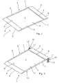
- Figure 1 shows a portable ramp 1 having an upper surface 2 comprising a recess 3 adapted to receive a mat (not shown).
- the recess is defined by a planar base 4, two transverse side walls 5, 5' and two lateral side walls 6, 6'.
- the depth of the recess 3 i.e. the height of the side walls 5, 5', 6 and 6' from the base 4 is around 2.5cm. This depth matches the typical depth of a doormat such that when a mat is in place in the recess, the upper surface of the mat is flush with the upper surface 2 of the ramp 1.
- the recess extends substantially to both of the transverse edges 7, 7' of the ramp i.e. the transverse walls 6, 6' of the recess 3 also define the transverse edges 7, 7' of the ramp 1.
- the transverse edges are those edges between which a user will pass without crossing.
- lateral edges 8, 8' are the edges which a user will cross when passing over the ramp 1. These lateral edges 8, 8' will, in use, contact the two positions joined or bridged by the ramp 1.
- the upper surface 2 comprises two surface portions 9, 9' which are inclined relative to the recess base surface 4.
- the inclined surface portions 9, 9' extend from the respective lateral edge 8, 8' of the ramp 1 to the recess 3. They are inclined symmetrically either side of the recess 3.
- the lower surface 13 of the ramp is substantially parallel to the recess base 4 and this will rest against steps in use.
- Figure 2 shows a second embodiment of the present invention which is the same as the first embodiment except that the ramp further comprises adjustment means 10, 10' for varying the vertical displacement between the lateral edges 8, 8' in use.
- the height adjustment means 10, 10' comprises two plates 11, 11' positioned on the transverse edges 7, 7' of the ramp 1 proximal one of the lateral edges 8 and each having a threaded hole.
- the threaded hole cooperates with a screw 12, 12', the length of the screw protruding either side of the plate 11, 11' being adjustable upon rotation of the screw 12, 12'.
- the end of the screws 12, 12' adjacent the lower surface 13 of the ramp 1 will abut the ground in use and by increasing the length of the screw 12, 12' located on the side of the plate 11, 11' proximal the lower surface 13, it is possible to raise the lateral end 8 proximal to which the plates 11, 11'are positioned.
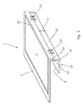
- Figure 5 shows a further embodiment of a ramp 1 having an upper surface 2 comprising a recess 3 adapted to receive a mat (not shown) and having alternative height adjustment means.
- the ramp 1 has a hinged surface portion 19 extending from the lateral edge 8 to the recess 3.
- the hinged surface portion is movable between a first position (not shown) in which it forms part of the upper surface 2 of the ramp 1 and a second position (shown In Figure 5 ) in which it is folded under the lower surface of the ramp 1.
- the hinged surface portion 19 has a first downwardly projecting extension 20 remote from the lateral edge 8. In the first position, the first downwardly projecting extension 20 is aligned in parallel with/against a second downwardly projecting extension 21 extending from the upper surface 2 of the ramp adjacent the recess 3.
- the lowermost (distal) ends, 22, 22' of the two downwardly projecting extensions, 20, 21 are joined by hinges 23, 23'.
- the hinged surface portion 19 is folded under the lower surface of the ramp such that the distal ends, 22, 22' of the two downwardly projecting extensions 20, 21, are abutment with the two downwardly projecting extensions being substantially coplanar.
- the proximal end 24 of the first downwardly projecting extension 20 i.e. the end remote from the hinge 23
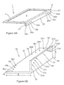
- Figure 6 shows a further embodiment of a ramp 1 having an upper surface 2 comprising a recess 3 adapted to receive a mat (not shown) and having yet further alternative height adjustment means.
- the recess and mat could be omitted.
- the ramp 1 has a down-turned lip 25 extending from the lateral end 8 which is uppermost in use.
- the down-turned lip includes two rows of diagonally spaced apertures 26a, 26b, 26c, 26d, 26a', 26b', 26c' and 26d' extending diagonally downwardly from adjacent the transverse edges 27, 27' of the down-turned lip 25 towards the vertical midline of the down-turned lip 25.
- the height adjustment means further comprises a metal plate 28 having a length matching the distance between the transverse edges 27, 27' of the down-turned lip.
- the plate 28 has an L-shaped cross-sectional area with a first portion 29 having a length A and a second portion 30 having a longer length B.
- the first portion 29 has a has two rows of diagonally spaced apertures 31 a, 31 b, 31 c, 31 d, 31a', 31b', 31c' and 31 d' extending diagonally upwards from adjacent the transverse edges 35, 35'of the first portion 29 towards the vertical midline of the first portion 29. There is a vertical spacing of 5 mm between each adjacent aperture in each row.
- the second portion 30 has two rows of diagonally spaced apertures 34a, 34b, 34c, 34d, 34a', 34b', 34c' and 34d' extending diagonally from adjacent the transverse edges 36, 36' of the second portion 30 towards the centre of the edge 37 of the second portion 30. There is a vertical spacing of 5 mm between each adjacent aperture in each row.
- the bent metal plate 28 is affixed to the down-turned lip using two nuts/bolts 38 (only one shown).
- the height adjustment means allows eight different height settings. In the lowest four settings, the down-turned lip 25 lies in abutment with the first portion 29 with the second portion 30 in contact with the ground. In the highest four settings, the down-turned lip 25 lies in abutment with the second portion 30 with the first portion 29 in contact with the ground.
- the nut/bolts 38 extend through the following pairs of apertures:
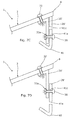
- Figure 7 shows a further embodiment of a ramp 1 having an upper surface 2 comprising a recess 3 adapted to receive a mat (not shown) and having yet further alternative height adjustment means.
- the recess and mat could be omitted.
- the ramp 1 has a down-turned lip 25' extending from the lateral end 8 which is uppermost in use.
- the down-turned lip is affixed proximal the uppermost lateral end by bolts 32 but it could be affixed by other mechanical fixtures or by welding/brazing.
- the down-turned lip includes two rows of horizontally aligned apertures 33a, 33b, 33c, 33d, 33a', 33b', 33c' and 33d' extending from adjacent the transverse edges 27, 27' of the down-turned lip 25 towards the vertical midline of the down-turned lip 25'.
- the height adjustment means further comprises a metal plate 28' having a length matching the distance between the transverse edges 27, 27' of the down-turned lip.
- the plate 28 has an angled contact end 40.
- the plate 28' has a has two rows of diagonally spaced apertures 41 a, 41 b, 41 c, 41 d, 41 a', 41 b', 41 c' and 41 d' extending diagonally upwards from adjacent the transverse edges 35, 35' of the plate 28' towards the vertical midline of the plate 28'. There is a vertical spacing of 5 mm between each adjacent aperture in each row. There is an extra pair of apertures 41 e, 41e' provided proximal the transverse edges 35, 35' of the plate with a maximum vertical spacing from the contact end 40 and vertically aligned with the apertures 41a, 41' having the minimum vertical spacing from the contact end.
- the metal plate 28' is affixed to the down-turned lip using nuts/bolts 38.
- the height adjustment means allows five different height settings.
- the nut/bolts 38 extend through the following pairs of apertures:
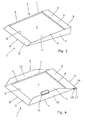
- Figure 3 shows a wedge ramp 1'.
- the upper surface 2 is separated from the lower surface 13 (which contacts the ground during use) by a wedge portion 14.
- the inclined surface portion 9 between the recess 3 and the lateral edge 8 which, in use, contacts the higher of the two positions is horizontal to the ground and to the lower surface 13.
- This type of ramp i.e. a wedge ramp
- the lower surface 13 of the wedge ramp 1' can rest fully on the ground and this helps makes the ramp stable and secure.
- the transverse edges 7, 7' of the ramp may be raised i.e. they comprise a respective upstanding wall 15, 15'. This helps guide the user over the ramp without any risk of falling off the transverse edges.
- One of the upstanding transverse walls 15' is provided with a handle 16 to facilitate handling and/or movement of the ramp 1.
- One of the lateral edges 8 is provided with an extension 16 having a down-turned lip 17.
- This extension and lip can be positioned over an obstruction such as a door threshold (e.g. a PVC door threshold) with the lip engaging the threshold to secure the ramp in position.
- a door threshold e.g. a PVC door threshold
- An underside of the lip (which, in use, contacts the threshold), is provided with a rubber strip 18 to minimise slippage.
Landscapes
- Health & Medical Sciences (AREA)
- Public Health (AREA)
- Architecture (AREA)
- Engineering & Computer Science (AREA)
- Veterinary Medicine (AREA)
- Life Sciences & Earth Sciences (AREA)
- Animal Behavior & Ethology (AREA)
- General Health & Medical Sciences (AREA)
- Structural Engineering (AREA)
- Civil Engineering (AREA)
- Carpets (AREA)
- Floor Finish (AREA)
- Legs For Furniture In General (AREA)
- Connection Of Plates (AREA)
- Conveying And Assembling Of Building Elements In Situ (AREA)
Applications Claiming Priority (2)
| Application Number | Priority Date | Filing Date | Title |
|---|---|---|---|
| GB1319544.1A GB2520013A (en) | 2013-11-05 | 2013-11-05 | Ramp |
| GBGB1404579.3A GB201404579D0 (en) | 2013-11-05 | 2014-03-14 | Ramp |
Publications (2)
| Publication Number | Publication Date |
|---|---|
| EP2868834A2 true EP2868834A2 (fr) | 2015-05-06 |
| EP2868834A3 EP2868834A3 (fr) | 2015-09-16 |
Family
ID=49767705
Family Applications (1)
| Application Number | Title | Priority Date | Filing Date |
|---|---|---|---|
| EP14191411.9A Withdrawn EP2868834A3 (fr) | 2013-11-05 | 2014-11-03 | Rampe |
Country Status (2)
| Country | Link |
|---|---|
| EP (1) | EP2868834A3 (fr) |
| GB (3) | GB2520013A (fr) |
Cited By (1)
| Publication number | Priority date | Publication date | Assignee | Title |
|---|---|---|---|---|
| US12031336B2 (en) | 2020-08-26 | 2024-07-09 | Wearwell, Llc | Integrated mat assembly and method of use |
Families Citing this family (1)
| Publication number | Priority date | Publication date | Assignee | Title |
|---|---|---|---|---|
| DE102017126361A1 (de) * | 2017-11-10 | 2019-05-16 | Gary Upmann | Transportable Rampe, insbesondere für Rollstühle oder Rollatoren |
Family Cites Families (10)
| Publication number | Priority date | Publication date | Assignee | Title |
|---|---|---|---|---|
| JPH09144258A (ja) * | 1995-11-16 | 1997-06-03 | Nippon Alum Co Ltd | スロープ装置 |
| US5707305A (en) * | 1996-10-28 | 1998-01-13 | True Pitch, Inc. | Portable pitching mound |
| JP2001123623A (ja) * | 1999-10-22 | 2001-05-08 | Suehiro Baba | スロープ台構造 |
| JP2002129721A (ja) * | 2000-10-27 | 2002-05-09 | Panefuri Kogyo Kk | 段差スロープ及び段差スロープ構造 |
| US6526614B2 (en) * | 2001-04-09 | 2003-03-04 | The United States Of America As Represented By The Secretary Of The Navy | Portable and lightweight ramp structure |
| JP2002349035A (ja) * | 2001-05-24 | 2002-12-04 | Hirase Kenchiku Sekkei:Kk | 介護住宅用スロープ形成方法 |
| DE202004006244U1 (de) * | 2004-04-21 | 2004-09-09 | Stegmaier, Hans-Peter | Vorrichtung zur Überbrückung einer Stufe |
| US7621831B2 (en) * | 2005-11-21 | 2009-11-24 | Cliff Lee Roberts | Portable pitching mound |
| ATE548219T1 (de) * | 2007-01-29 | 2012-03-15 | Rolfo Spa | Eingriffvorrichtung zur regulierung der betriebsposition von manuellen platten für belade-/entladefahrzeuge |
| US8844083B2 (en) * | 2011-09-01 | 2014-09-30 | Thruflow, Inc. | Adjustable, modular handicap-access-ramp system |
-
2013
- 2013-11-05 GB GB1319544.1A patent/GB2520013A/en not_active Withdrawn
-
2014
- 2014-03-14 GB GBGB1404579.3A patent/GB201404579D0/en not_active Ceased
- 2014-11-03 EP EP14191411.9A patent/EP2868834A3/fr not_active Withdrawn
- 2014-11-03 GB GB1419517.6A patent/GB2520834B/en active Active
Cited By (1)
| Publication number | Priority date | Publication date | Assignee | Title |
|---|---|---|---|---|
| US12031336B2 (en) | 2020-08-26 | 2024-07-09 | Wearwell, Llc | Integrated mat assembly and method of use |
Also Published As
| Publication number | Publication date |
|---|---|
| GB201404579D0 (en) | 2014-04-30 |
| EP2868834A3 (fr) | 2015-09-16 |
| GB201319544D0 (en) | 2013-12-18 |
| GB2520834A (en) | 2015-06-03 |
| GB201419517D0 (en) | 2014-12-17 |
| GB2520834B (en) | 2020-05-20 |
| GB2520013A (en) | 2015-05-13 |
Similar Documents
| Publication | Publication Date | Title |
|---|---|---|
| US4596729A (en) | Non-slip floor mat assembly | |
| US6942419B2 (en) | Grate assembly | |
| US9091120B2 (en) | Collabsible platform assembly for an extension ladder | |
| US9803381B1 (en) | Ramp and/or platform assembly | |
| US10092122B2 (en) | Slip resistant mat with stabilizing projections | |
| MX2014005951A (es) | Montaje de abrazadera de zapato para montura a una parte inferior de un riel de escalera. | |
| EP3102748A2 (fr) | Grille de couverture | |
| EP3539520B1 (fr) | Structure de rampe | |
| KR102196258B1 (ko) | 소음감쇄기능을 갖는 조립식 알루미늄 바닥재 | |
| EP2868834A2 (fr) | Rampe | |
| KR101542811B1 (ko) | 발판을 구비한 컨테이너 하우스 | |
| KR200451675Y1 (ko) | 안전보호구용 계단커버 | |
| US7540067B2 (en) | Fastener for fixing an edge portion of a resilient material to a surface | |
| KR102343195B1 (ko) | 건축물용 계단 논슬립 구조 | |
| KR102145587B1 (ko) | 신발 먼지털이용 발판 | |
| US8702069B1 (en) | Guard rail system | |
| GB2390391A (en) | Ladder stabiliser | |
| US6497304B1 (en) | Step ladder | |
| KR100668055B1 (ko) | 공동주택용 계단의 논슬립구조 | |
| KR20150111758A (ko) | 건물용 비상탈출시스템 | |
| KR20180073916A (ko) | 논슬립 | |
| KR102809255B1 (ko) | 내구성 및 지지력이 향상된 금속데크 | |
| WO2017031523A1 (fr) | Élément de fixation pour une échelle | |
| EP3321421B1 (fr) | Drain à fente | |
| KR20170027037A (ko) | 횡단보도 진출입로의 도로경계석 |
Legal Events
| Date | Code | Title | Description |
|---|---|---|---|
| PUAI | Public reference made under article 153(3) epc to a published international application that has entered the european phase |
Free format text: ORIGINAL CODE: 0009012 |
|
| 17P | Request for examination filed |
Effective date: 20141103 |
|
| AK | Designated contracting states |
Kind code of ref document: A2 Designated state(s): AL AT BE BG CH CY CZ DE DK EE ES FI FR GB GR HR HU IE IS IT LI LT LU LV MC MK MT NL NO PL PT RO RS SE SI SK SM TR |
|
| AX | Request for extension of the european patent |
Extension state: BA ME |
|
| PUAL | Search report despatched |
Free format text: ORIGINAL CODE: 0009013 |
|
| AK | Designated contracting states |
Kind code of ref document: A3 Designated state(s): AL AT BE BG CH CY CZ DE DK EE ES FI FR GB GR HR HU IE IS IT LI LT LU LV MC MK MT NL NO PL PT RO RS SE SI SK SM TR |
|
| AX | Request for extension of the european patent |
Extension state: BA ME |
|
| RIC1 | Information provided on ipc code assigned before grant |
Ipc: A61G 3/06 20060101ALI20150813BHEP Ipc: E04F 11/00 20060101AFI20150813BHEP |
|
| STAA | Information on the status of an ep patent application or granted ep patent |
Free format text: STATUS: THE APPLICATION IS DEEMED TO BE WITHDRAWN |
|
| 18D | Application deemed to be withdrawn |
Effective date: 20160317 |