EP2868932B1 - Vollintegrierter elektrohydraulischer Linearaktuator - Google Patents
Vollintegrierter elektrohydraulischer Linearaktuator Download PDFInfo
- Publication number
- EP2868932B1 EP2868932B1 EP14186455.3A EP14186455A EP2868932B1 EP 2868932 B1 EP2868932 B1 EP 2868932B1 EP 14186455 A EP14186455 A EP 14186455A EP 2868932 B1 EP2868932 B1 EP 2868932B1
- Authority
- EP
- European Patent Office
- Prior art keywords
- pump
- hydraulic
- fluid
- motor
- cylinder
- Prior art date
- Legal status (The legal status is an assumption and is not a legal conclusion. Google has not performed a legal analysis and makes no representation as to the accuracy of the status listed.)
- Active
Links
Images


Classifications
-
- F—MECHANICAL ENGINEERING; LIGHTING; HEATING; WEAPONS; BLASTING
- F15—FLUID-PRESSURE ACTUATORS; HYDRAULICS OR PNEUMATICS IN GENERAL
- F15B—SYSTEMS ACTING BY MEANS OF FLUIDS IN GENERAL; FLUID-PRESSURE ACTUATORS, e.g. SERVOMOTORS; DETAILS OF FLUID-PRESSURE SYSTEMS, NOT OTHERWISE PROVIDED FOR
- F15B15/00—Fluid-actuated devices for displacing a member from one position to another; Gearing associated therewith
- F15B15/18—Combined units comprising both motor and pump
-
- F—MECHANICAL ENGINEERING; LIGHTING; HEATING; WEAPONS; BLASTING
- F15—FLUID-PRESSURE ACTUATORS; HYDRAULICS OR PNEUMATICS IN GENERAL
- F15B—SYSTEMS ACTING BY MEANS OF FLUIDS IN GENERAL; FLUID-PRESSURE ACTUATORS, e.g. SERVOMOTORS; DETAILS OF FLUID-PRESSURE SYSTEMS, NOT OTHERWISE PROVIDED FOR
- F15B1/00—Installations or systems with accumulators; Supply reservoir or sump assemblies
- F15B1/02—Installations or systems with accumulators
- F15B1/025—Installations or systems with accumulators used for thermal compensation, e.g. to collect expanded fluid and to return it to the system as the system fluid cools down
-
- F—MECHANICAL ENGINEERING; LIGHTING; HEATING; WEAPONS; BLASTING
- F15—FLUID-PRESSURE ACTUATORS; HYDRAULICS OR PNEUMATICS IN GENERAL
- F15B—SYSTEMS ACTING BY MEANS OF FLUIDS IN GENERAL; FLUID-PRESSURE ACTUATORS, e.g. SERVOMOTORS; DETAILS OF FLUID-PRESSURE SYSTEMS, NOT OTHERWISE PROVIDED FOR
- F15B15/00—Fluid-actuated devices for displacing a member from one position to another; Gearing associated therewith
- F15B15/08—Characterised by the construction of the motor unit
- F15B15/14—Characterised by the construction of the motor unit of the straight-cylinder type
- F15B15/1423—Component parts; Constructional details
- F15B15/1466—Hollow piston sliding over a stationary rod inside the cylinder
-
- F—MECHANICAL ENGINEERING; LIGHTING; HEATING; WEAPONS; BLASTING
- F15—FLUID-PRESSURE ACTUATORS; HYDRAULICS OR PNEUMATICS IN GENERAL
- F15B—SYSTEMS ACTING BY MEANS OF FLUIDS IN GENERAL; FLUID-PRESSURE ACTUATORS, e.g. SERVOMOTORS; DETAILS OF FLUID-PRESSURE SYSTEMS, NOT OTHERWISE PROVIDED FOR
- F15B2211/00—Circuits for servomotor systems
- F15B2211/20—Fluid pressure source, e.g. accumulator or variable axial piston pump
- F15B2211/205—Systems with pumps
- F15B2211/20507—Type of prime mover
- F15B2211/20515—Electric motor
-
- F—MECHANICAL ENGINEERING; LIGHTING; HEATING; WEAPONS; BLASTING
- F15—FLUID-PRESSURE ACTUATORS; HYDRAULICS OR PNEUMATICS IN GENERAL
- F15B—SYSTEMS ACTING BY MEANS OF FLUIDS IN GENERAL; FLUID-PRESSURE ACTUATORS, e.g. SERVOMOTORS; DETAILS OF FLUID-PRESSURE SYSTEMS, NOT OTHERWISE PROVIDED FOR
- F15B2211/00—Circuits for servomotor systems
- F15B2211/20—Fluid pressure source, e.g. accumulator or variable axial piston pump
- F15B2211/205—Systems with pumps
- F15B2211/2053—Type of pump
- F15B2211/20561—Type of pump reversible
-
- F—MECHANICAL ENGINEERING; LIGHTING; HEATING; WEAPONS; BLASTING
- F15—FLUID-PRESSURE ACTUATORS; HYDRAULICS OR PNEUMATICS IN GENERAL
- F15B—SYSTEMS ACTING BY MEANS OF FLUIDS IN GENERAL; FLUID-PRESSURE ACTUATORS, e.g. SERVOMOTORS; DETAILS OF FLUID-PRESSURE SYSTEMS, NOT OTHERWISE PROVIDED FOR
- F15B2211/00—Circuits for servomotor systems
- F15B2211/20—Fluid pressure source, e.g. accumulator or variable axial piston pump
- F15B2211/27—Directional control by means of the pressure source
-
- F—MECHANICAL ENGINEERING; LIGHTING; HEATING; WEAPONS; BLASTING
- F15—FLUID-PRESSURE ACTUATORS; HYDRAULICS OR PNEUMATICS IN GENERAL
- F15B—SYSTEMS ACTING BY MEANS OF FLUIDS IN GENERAL; FLUID-PRESSURE ACTUATORS, e.g. SERVOMOTORS; DETAILS OF FLUID-PRESSURE SYSTEMS, NOT OTHERWISE PROVIDED FOR
- F15B2211/00—Circuits for servomotor systems
- F15B2211/30—Directional control
- F15B2211/305—Directional control characterised by the type of valves
- F15B2211/30505—Non-return valves, i.e. check valves
- F15B2211/30515—Load holding valves
-
- F—MECHANICAL ENGINEERING; LIGHTING; HEATING; WEAPONS; BLASTING
- F15—FLUID-PRESSURE ACTUATORS; HYDRAULICS OR PNEUMATICS IN GENERAL
- F15B—SYSTEMS ACTING BY MEANS OF FLUIDS IN GENERAL; FLUID-PRESSURE ACTUATORS, e.g. SERVOMOTORS; DETAILS OF FLUID-PRESSURE SYSTEMS, NOT OTHERWISE PROVIDED FOR
- F15B2211/00—Circuits for servomotor systems
- F15B2211/60—Circuit components or control therefor
- F15B2211/625—Accumulators
-
- F—MECHANICAL ENGINEERING; LIGHTING; HEATING; WEAPONS; BLASTING
- F15—FLUID-PRESSURE ACTUATORS; HYDRAULICS OR PNEUMATICS IN GENERAL
- F15B—SYSTEMS ACTING BY MEANS OF FLUIDS IN GENERAL; FLUID-PRESSURE ACTUATORS, e.g. SERVOMOTORS; DETAILS OF FLUID-PRESSURE SYSTEMS, NOT OTHERWISE PROVIDED FOR
- F15B2211/00—Circuits for servomotor systems
- F15B2211/70—Output members, e.g. hydraulic motors or cylinders or control therefor
- F15B2211/705—Output members, e.g. hydraulic motors or cylinders or control therefor characterised by the type of output members or actuators
- F15B2211/7051—Linear output members
- F15B2211/7053—Double-acting output members
- F15B2211/7054—Having equal piston areas
-
- F—MECHANICAL ENGINEERING; LIGHTING; HEATING; WEAPONS; BLASTING
- F15—FLUID-PRESSURE ACTUATORS; HYDRAULICS OR PNEUMATICS IN GENERAL
- F15B—SYSTEMS ACTING BY MEANS OF FLUIDS IN GENERAL; FLUID-PRESSURE ACTUATORS, e.g. SERVOMOTORS; DETAILS OF FLUID-PRESSURE SYSTEMS, NOT OTHERWISE PROVIDED FOR
- F15B7/00—Systems in which the movement produced is definitely related to the output of a volumetric pump; Telemotors
- F15B7/005—With rotary or crank input
- F15B7/006—Rotary pump input
Definitions
- the present disclosure relates in general to hydraulic control systems using hydraulic cylinders as linear actuators and in particular to a compact, fully integrated electro-hydraulic linear actuator device of universal usage, being practically maintenance-free and deployable in innumerable applications, needing solely an electrical cable connection to a control unit.
- An electromechanical system typically comprises transmissions, gears and endless screw devices in order to transform the rotation motion of an electrical motor in a linear motion and suffers from relatively large "start off" frictional forces.
- relatively low supply voltage applications e.g. in vehicles
- start-up currents and large cross sections of the cable conductors imply large start-up currents and large cross sections of the cable conductors.
- the mechanical components employed require a good wear resistance and high precision machining; aspects that make the device relatively expensive.
- Pneumatic actuators typically pneumatic cylinders, driven by a source of compressed air through electrically controlled valves, function at relatively low pressure and thus have relatively large sizes hardly compatible with a requirement of reducing encumbrances.
- Hydraulic actuators consists of one or even several double effect cylinders in parallel (for heavy duty applications) the piston or pistons of which are driven with a work fluid, for example a mineral oil, that is pressurized by a pump, commonly a volumetric pump associated to a reservoir of hydraulic fluid.
- a work fluid for example a mineral oil
- a pump commonly a volumetric pump associated to a reservoir of hydraulic fluid.
- Control of the double effect piston or pistons is implemented through electrically controlled valves, normally installed in a hydraulic port array of hydraulic connections, associated to a centralized control unit, from which depart pipes or hoses of connection to the respective chambers of the double effect cylinders.
- CA 2313943 discloses a hydraulic system according to the preamble of claim 1.
- the volume of hydraulic working fluid is markedly reduced by eliminating any reservoir and providing fluid chambers of identical areas over opposite sides of the double effect piston.
- This allows an enhanced compactness, the possibility of embedding practically the whole hydraulic circuit within a base block of the cylinder, including paired hydraulically piloted valves and safety relief valves, and to associate to the base block, a reversible drive motor and pump assembly.
- a magnetic coupling between the motor and the pump avoids the presence of rotary seal packing for long lasting seal proofness.
- the hydraulic circuit may be factory-charged with de-aerated hydraulic fluid and remains permanently sealed. Installation of the fully integrated electro-hydraulic linear actuator simply requires electrical connection of the reversible drive motor to a control unit.
- the projecting stem is the double effect piston itself, in form of an end capped tube that moves inward and outward of a fixed cylinder, solidly connected to a fluid distribution base block, associated to a motor-pump assembly block.
- the movable tubular stem-piston is closed at the outer end by a cap and adapter assembly and sealingly slides inside the fixed cylinder and over a fixed tubular inner stem, axially extending from the fluid distribution base block for hydraulically connecting an upper chamber inside the end-capped movable stem to the hydraulic circuit of the double effect piston, the circular sectional area of which is identical to the circular sectional crown area of a lower chamber, defined between the fixed tubular inner stem and the fixed cylinder.
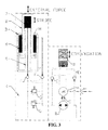
- FIG. 1 The basic hydraulic circuit diagram of an electro-hydraulic linear actuator device of this disclosure is depicted in Figure 1 .
- the components namely: the electric motor A of reversible direction of rotation, the volumetric pump B driven by the motor and the hydraulic cylinder 3 are symbolically represented, alike the other circuital components.
- a double effect piston H integral to a mobile stem 2 separates a first or upper chamber 7 from a second or lower chamber 8, functionally defined on opposite sides of the piston.
- the work fluid driven by the reversibly driven pump is injected and drawn to and from the two chambers 7 and 8 when extracting or retracting the mobile stem 2, or blocked in the chamber when holding in position the stem-piston.
- the correct circuital configuration is implemented by the hydraulically controlled pair of blocking valves F.
- the hydraulic circuit further comprises at least a compressible air chamber D adapted to compensate internal thermal expansions/contractions, which is functionally connected to the pump inlet side branch of the hydraulic circuit, according to the commanded circuital configuration of the actuator.
- Hydraulic fluid flow path selecting means E may, for example, be in form of a pair of hydraulically piloted valves or shuttle valves of any other functionally equivalent device.
- the mechanical coupling of the motor spindle to the pump rotor is implemented with a magnetic coupling. Elimination of a seal packing over a rotating spindle, far more subject to wear than linearly acting seal rings, is amenable to the production of the factory filled fully integrated device of this disclosure that is substantially sealed for its whole operative lifetime.
- FIGS 2 to 5b replicate the circuit diagram of Figure 1 for illustrating the configuration that the circuit assumes in distinct phases of operation, essentially implemented by the two pairs of hydraulically piloted devices F and E and by the volumetric pump B, reversibly driven by the reversible electrical motor A.
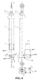
- Figure 6 shows orthogonal views of an exemplary embodiment of electro-hydraulic linear actuator device of the present disclosure, in fully retracted position, with indications of significant sectional planes.
- the device maintains the stem extending from a single side end of the cylinder 3 and at the same time the two fluid chambers, 7 and 8, respectively, are made with identical cross sectional area.
- This is achieved by employing a tubular mobile stem-piston 2, closed at the outer end, and delimiting at its interior a first or upper chamber 7, into which the working fluid, injected by a pump B, eventually pushes the tubular stem-piston 2 to project out of the cylinder 3, terminating with a common oil scraper, slydring and seal ring assembly 6, while its engrossed inner end 2p, provided with oil scraper, slydring and seal ring, sealingly slides inside the cylinder 3, expelling working fluid out of a second or lower chamber 8, defined over the wetted outer cylindrical surface of the mobile tubular stem-piston 2.
- the circular cross sectional area of the upper chamber 7 and the circular-crown, cross sectional area of the lower chamber 8 are made identical. Delimitation of the upper chamber 7 is achieved by a coaxial, inner fixed piston-stem 9, provided with oil scraper, slydring and seal ring at its end, over which the movable stem-piston 2 sealingly slides, and through which a hydraulic connection bore 9d connects the upper chamber 7 to the hydraulic circuit.
- the double effect stem-piston extending from a single side end of the cylinder, permits to form the whole functional hydraulic circuit in a composite fluid distribution block 4 at the closed end of the cylinder 3 and to embed a volumetric pump B and, preferably, even a magnetic coupling C with the shaft of a reversible electric motor A, fastened onto the block.
- the electro-hydraulic linear actuator device of this disclosure is powered through a reversible direction electrical motor A that drives a volumetric pump B, preferably through a magnetic coupling C, and control is implemented through a pair of hydraulically piloted blocking valves F of the conduits to the two chambers 7 and 8 and a pair of hydraulically piloted valves E for switching the connection of the compensation chamber D to the fluid return branch of the hydraulic circuit when inverting the direction of pumping.
- a pair of safety relief valves G of excessive pressure between the paths of fluid circulation to and from the chambers of the linear hydraulic actuator complete the hydraulic system.
- the hydraulic circuit may thus be wholly pre-filled with properly de-gassed working fluid and permanently sealed at the factory, for a long operative life, substantially maintenance-free.
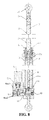
- a motor-pump assembly split block composed of two parts 4ex1 and 4ex2 solidly connected together to form a composite solid block.
- the magnetic coupling C, the volumetric pump B, compressible air chambers of volumetric compensation D and related hydraulically piloted valves E (re: Figure 1 ) and appropriate hydraulic fluid flow connection ports are realized in such a side connected split assembly block, associated to the cylinder base block 4, thus fully integrating the hydraulic circuit and relative drive and +hydraulically piloted elements.
- association of the motor-pump assembly split block, 4ex1 and 4ex2, to the cylinder base block 4 is made in a way that allows to orient it in a most favourable angled position relative to the cylinder axis and to fix it in that coupled position, by providing a pin 11 that preserves circuital coherent fluid path continuity when rotating the motor-pump assembly split block with respect to the cylinder base block (i.e. the actuator axis) to a position that will not interfere with structural members or organs of the host machinery.
- Figure 9 is an enlarged detail cross sectional view on the sectional plane c-c of Figure 6 , showing the way the pair of hydraulically piloted blocking valves F (re: Figure 1 ) of the conduits leading to the inlet/outlet ports of the reversible volumetric pump B, for selectively connecting them to the two chambers (7 and 8) of the double effect hydraulic actuator during stem extraction and retraction phases, and for closing both of them for retaining a position, are realized inside respective borings in the lower part 4ex2 of the motor-pump assembly split block, that are normally closed by plugs.
- the pair of hydraulically piloted blocking valves F (re: Figure 1 ) of the conduits leading to the inlet/outlet ports of the reversible volumetric pump B, for selectively connecting them to the two chambers (7 and 8) of the double effect hydraulic actuator during stem extraction and retraction phases, and for closing both of them for retaining a position
- the pin 11 partially extends in coaxial borings, respectively into the cylinder base block 4 and into the lower part 4ex2 of the motor-pump assembly split block and has circular grooves adapted to co-ordinately intercept hydraulic circuit conduits in the semi block 4ex2 and in the base block 4, internal fluid distribution conduits and O-ring seals in order to preserve circuital coherent fluid paths continuity whenever should become necessary to rotate the motor-pump assembly split block with respect to the cylinder base block (i.e. the actuator axis) because of existing encumbrances in the host machinery.
- Figure 10 is an enlarged detail cross sectional view on the sectional plane d-d of Figure 6 , showing the way a pair of spring-loaded safety relief valves G (re: Figure 1 ) may be realized inside respective borings in the cylinder base block 4, with spring load trim plugs, provided with an O-ring seal.
- Figure 11 is an enlarged detail cross sectional view on the sectional plane e-e of Figure 6 , showing the way compensation compressible air chambers D delimited by a spring loaded piston are realized in the upper part 4ex1 of the motor-pump assembly split block.
- Figures 12 , 13 , 14 and 15 are other cross sectional views useful for a more easily recognition of certain details of the integrated pump and related hydraulic circuital features.
- the pump B is a volumetric, rotary pistons pump, the rotor 12 of which has radial borings into which move pistons 101 held in abutment against the surface of the inner ring of the eccentric ball bearing 13 by the centrifugal force generated by the rotation of the rotor 12.
- the rotor 12 turns over the hydraulic fluid distributor pin 19, held in a blind hole of the lower part 4ex2 of the motor-pump assembly split block. Therefore, the pistons 101 have an alternated inward and outward radial motion (toward and away from the center pin 19), obligated by their abutment onto the the surface of the inner ring of the eccentric ball bearing 13, which make them deliver hydraulic fluid to the hydraulic circuit when traveling inward and draw-in fluid from the hydraulic circuit when traveling outward, through delivery and return ports 19a and 19b and conduits 19c, 19d, present in the fluid distribution pin 19.
- the pump system is reversible: changing the direction of rotation delivery and return paths automatically invert themselves.
- the hydraulically driven valves E are also integrated within the lower part 4-ex2 of the motor-pump assembly split block, one for each branch of the hydraulic circuit, leading to the work fluid side cavity of a compressible air chamber of negligible volumetric requirement, in consideration of the fact that compensation need to account only for thermal expansions/expansions of the work fluid.
- Drain function if for any reason (thermal expansion of the circulating fluid), the pressure of the work fluid in the hydraulic circuit should rise, the hydraulically controlled valve E will similarly open releasing an exceeding volume of fluid out of the circuit through the conduit 106, toward the associated integrated volumetric compensator D.
- the electrical motor A magnetically coupled to the embedded pump B (re: Figures 6 , 7 and 8 ), is fixed atop the upper part 4ex1 of the motor-pump assembly split block.
Landscapes
- Engineering & Computer Science (AREA)
- Physics & Mathematics (AREA)
- Fluid Mechanics (AREA)
- Mechanical Engineering (AREA)
- General Engineering & Computer Science (AREA)
- Actuator (AREA)
Claims (2)
- Ein integrierter, elektrohydraulischer Linearaktuator (1) ohne jegliches Reservoir für ein Arbeitsfluid, umfassend:- einen Elektromotor (A) mit reversibler Drehrichtung,- eine von dem besagten Motor angetriebene, reversible Volumenpumpe (B),- einen Hydraulikzylinder (3),- in dem besagten Zylinder einen doppelt wirkenden Kolben (H) samt beweglicher Kolbenstange, welcher eine erste Kammer (7) von einer zweiten Kammer (8) trennt, die von den gegenüber liegenden Seiten des Kolbens funktionell abgegrenzt sind,- einen von der besagten Pumpe angetriebenen Hydraulikkreis zum Hineinleiten und Herausziehen eines hydraulischen Arbeitsfluids in und aus den besagten Kammern (7, 8), umfassend hydraulisch gesteuerte Ventile,- eine Kammer (D) für komprimierbare Luft zur Volumenkompensation von thermischen Ausdehnungen/Kontraktionen,- einem hydraulisch gesteuerten Mittel (E) zur Auswahl eines Fluid-Pfades, der eine einem Arbeitsfluid zugeordnete Seite der besagten Kammer (D) für komprimierbare Luft zur Volumenkompensation mit dem Saugzweig der reversiblen Pumpe des Hydraulikkreises verbindet,- ein Paar von hydraulisch gesteuerten Absperrventilen (F) an den jeweiligen Leitungen, welche die besagten Kammern (7, 8) mit dein Einlass-/Auslassanschlüssen der besagten Pumpe (B) verbinden,- federvorgespannte Sicherheits-Überdruckablassventile (G) in jeweiligen Umleitungs-Pfaden zwischen den Pumpensaug- und Pumpenförderzweigen in dem Hydraulikkreis,wobeia) die besagte Kolbenstange (2) nur aus einem Ende des besagten Zylinders (3) herausragt, und wobei die besagten Fluidkammern (7, 8) identische Querschnittsbereiche aufweisen;b) wobei der besagte Zylinder (3) an einem Sockelblock (4) fest angeschlossen ist, welcher einem geteilten Block (4ex1, 4ex2) einer Motor-Pumpen-Baugruppe zugeordnet ist, wobei die besagte Kolbenstange (2) rohrförmig und an ihrem äußeren Ende durch eine Baugruppe mit einer Kappe (5) und einem Adapter (10) verschlossen ist, und dichtend in den besagten Zylinder (3) hinein und aus diesem heraus gleitet, sowie über einer festgelegten, inneren Stange (9), welche sich in axialer Richtung von dem besagten Sockelblock (4) zur Verteilung des besagten Fluids weg erstreckt und eine Längsbohrung aufweist zur hydraulischen Verbindung mit einer oberen Kammer (7) innerhalb der endseitig durch eine Kappe verschlossenen, rohrförmigen beweglichen Stange (2) des Hydraulikkreises des doppelt wirkenden Kolbens, dessen kreisförmiger Querschnittsbereich identisch zu dem kreisförmigen Kranzbereich der unteren Kammer (8) ist, die zwischen der besagten, beweglichen Kolbenstange (2) und dem besagten Zylinder (3) definiert ist; dadurch gekennzeichnet, dassc) die reversible Pumpe (B) zwischen einem ersten Teil (4ex1) und einem zweiten Teil (4ex2) des besagten, geteilten Blockes (4ex1, 4ex2) eingebettet ist, wobei eine Welle (14) desselben von dem besagten Motor (A) über eine innerhalb eines ersten Teils (4ex1) der Motor-Pumpen-Blockbaugruppe angeordnete Magnetkupplung (C) angetrieben wird;d) wenigstens eine Kammer (D) für komprimierbare Luft zur Volumenkompensation von thermischen Ausdehnungen/Kontraktionen innerhalb einer oder mehrerer innerer Bohrungen des besagten ersten Teils (4ex1) der besagten Motor-Pumpen-Blockbaugruppe abgegrenzt ist;e) das besagte, hydraulisch gesteuerte Mittel (E) zur Auswahl eines Fluid-Pfades die Form von zwei hydraulisch gesteuerten Ventilen hat, welche geeignet sind, Pfade für das Arbeitsfluid zwischen dem Pumpenförderzweig bzw. dem Pumpensaugzweig des Hydraulikkreises und wenigstens einer dem Hydraulikfluid zugeordneten Seite der Kammer (D) für komprimierbare Luft zur Volumenkompensation zu unterbrechen.
- Der elektrohydraulische Linearaktuator nach Anspruch 1, wobei die besagte, geteilte Motor-Pumpen-Blockbaugruppe (4ex1, 4ex2) an dem besagten Zylinder-Sockelblock (4) unter verschiedenen, auswählbaren Neigungen befestigbar ist, mit einem Stift (11), der sich teilweise in koaxialen Bohrungen in dem Zylindersockelblock (4) und in dem unteren Teil (4ex2) der geteilten Motor-Pumpen-Blockbaugruppe erstreckt, mit kreisförmigen Nuten, welche in der Lage sind, koordiniert die Leitungen des Hydraulikkreises in dem Block (4ex2) und in dem Sockel block (4) zu unterbrechen, mit internen Fluidverteilungsleitungen und O-Ring-Dichtungen, welche in der Lage sind, in dem Kreis eine kohärente Kontinuität des Fluidpfades zu erhalten.
Applications Claiming Priority (1)
| Application Number | Priority Date | Filing Date | Title |
|---|---|---|---|
| IT001586A ITMI20131586A1 (it) | 2013-09-26 | 2013-09-26 | Attuatore idraulico lineare interamente integrato |
Publications (2)
| Publication Number | Publication Date |
|---|---|
| EP2868932A1 EP2868932A1 (de) | 2015-05-06 |
| EP2868932B1 true EP2868932B1 (de) | 2016-10-19 |
Family
ID=49554384
Family Applications (1)
| Application Number | Title | Priority Date | Filing Date |
|---|---|---|---|
| EP14186455.3A Active EP2868932B1 (de) | 2013-09-26 | 2014-09-25 | Vollintegrierter elektrohydraulischer Linearaktuator |
Country Status (3)
| Country | Link |
|---|---|
| EP (1) | EP2868932B1 (de) |
| ES (1) | ES2611488T3 (de) |
| IT (1) | ITMI20131586A1 (de) |
Families Citing this family (10)
| Publication number | Priority date | Publication date | Assignee | Title |
|---|---|---|---|---|
| NO20150966A1 (en) * | 2015-07-24 | 2017-01-25 | Macgregor Norway As | Hydraulic actuator |
| CN105387019A (zh) * | 2015-12-25 | 2016-03-09 | 河海大学常州校区 | 一种内置导向油缸 |
| WO2017210492A1 (en) | 2016-06-02 | 2017-12-07 | ClearMotion, Inc. | Systems and methods for managing noise in compact high speed and high force hydraulic actuators |
| IT201800001627A1 (it) * | 2018-01-22 | 2019-07-22 | Scm Group Spa | Sistema pneumatico di attuazione e macchina utensile su cui detto sistema è installato. |
| US11999214B2 (en) | 2018-06-14 | 2024-06-04 | ClearMotion, Inc. | Accumulators for a distributed active suspension system |
| EP3730806B1 (de) * | 2019-04-24 | 2023-01-18 | Piston Power s.r.o. | Hydraulische aktuatoranordnung |
| IT201900008559A1 (it) | 2019-06-10 | 2020-12-10 | Levati Food Tech S R L | Apparato di trattamento termico di prodotti |
| FI130288B (fi) * | 2019-11-04 | 2023-06-02 | Norrhydro Oy | Sähköhydraulinen toimilaite |
| IT202200019797A1 (it) * | 2022-09-27 | 2024-03-27 | Automa By Magic S R L | Dispositivo di azionamento di stampi |
| IT202300003765A1 (it) * | 2023-03-02 | 2024-09-02 | G A P S P A | Attuatore oleodinamico |
Family Cites Families (6)
| Publication number | Priority date | Publication date | Assignee | Title |
|---|---|---|---|---|
| US3335642A (en) * | 1965-01-08 | 1967-08-15 | Borje O Rosaen | Cylinder construction |
| US3949650A (en) * | 1975-01-16 | 1976-04-13 | Blatt Leland F | Equal area displacement hydraulic cylinder |
| US4155236A (en) * | 1978-01-23 | 1979-05-22 | Anderson-Cook, Inc. | Tooth forming machine |
| CA2279435A1 (en) * | 1999-07-30 | 2001-01-30 | Michael Alexander Duff | Linear actuator |
| DE102005061730B4 (de) * | 2005-11-18 | 2009-07-23 | Tr Electronic Gmbh | Vorrichtung zum Bewegen eines Kolbens |
| US9273703B2 (en) * | 2010-09-16 | 2016-03-01 | Parker-Hannifin Corporation | Universal orientation electro-hydraulic actuator |
-
2013
- 2013-09-26 IT IT001586A patent/ITMI20131586A1/it unknown
-
2014
- 2014-09-25 ES ES14186455.3T patent/ES2611488T3/es active Active
- 2014-09-25 EP EP14186455.3A patent/EP2868932B1/de active Active
Also Published As
| Publication number | Publication date |
|---|---|
| ITMI20131586A1 (it) | 2015-03-27 |
| EP2868932A1 (de) | 2015-05-06 |
| ES2611488T3 (es) | 2017-05-09 |
Similar Documents
| Publication | Publication Date | Title |
|---|---|---|
| EP2868932B1 (de) | Vollintegrierter elektrohydraulischer Linearaktuator | |
| US3021869A (en) | Rotary type hydraulic valve | |
| EP1837530B1 (de) | Betätigungsvorrichtung | |
| US20100300279A1 (en) | Point Of Use Actuator | |
| CA2930600C (en) | Fluid pump for a linear actuator | |
| CA2945210C (en) | Drill stem safety valve actuator | |
| US20160252190A1 (en) | Valve assembly and method of cooling | |
| DE102017206506A1 (de) | Elektrohydraulisches System für den Einsatz unter Wasser mit einem elektrohydraulischen Stellantrieb | |
| CN212079617U (zh) | 双向内啮合齿轮马达泵及其液压系统 | |
| US20200080662A1 (en) | Valve assembly and method of cooling | |
| US9803661B2 (en) | Valve having right-angle proportional and directional pilot actuators | |
| CN207377753U (zh) | 一种直流变量定子永磁式集成动力装置 | |
| US9897228B2 (en) | Valve having opposing right-angle actuators | |
| US11459889B2 (en) | Hydraulic arrangement for a steered wheel of a vehicle | |
| CN104676045B (zh) | 一种水介质两位三通换向阀 | |
| CN115095566A (zh) | 一种车载用集成化伺服电机泵调平支腿机构 | |
| DE10320456A1 (de) | Schwenkmotor | |
| CN107605696A (zh) | 一种直流变量定子永磁式集成动力装置 | |
| CN204828778U (zh) | 一种水介质两位三通换向阀 | |
| US12259029B2 (en) | Linear actuator | |
| US6578357B1 (en) | Regulating device for hydraulic working tools | |
| EP3265665B1 (de) | Ventilanordnung | |
| KR20240118839A (ko) | 전기 모터, 유압 펌프, 및 전자 구동 디바이스의 통합 조립체 및 연관 냉각 구성 | |
| CN110307191B (zh) | 液控自动补偿式增压装置 | |
| US20160319807A1 (en) | Self-bleeding, self-priming, reversible circuit |
Legal Events
| Date | Code | Title | Description |
|---|---|---|---|
| PUAI | Public reference made under article 153(3) epc to a published international application that has entered the european phase |
Free format text: ORIGINAL CODE: 0009012 |
|
| 17P | Request for examination filed |
Effective date: 20140925 |
|
| AK | Designated contracting states |
Kind code of ref document: A1 Designated state(s): AL AT BE BG CH CY CZ DE DK EE ES FI FR GB GR HR HU IE IS IT LI LT LU LV MC MK MT NL NO PL PT RO RS SE SI SK SM TR |
|
| AX | Request for extension of the european patent |
Extension state: BA ME |
|
| R17P | Request for examination filed (corrected) |
Effective date: 20150717 |
|
| RBV | Designated contracting states (corrected) |
Designated state(s): AL AT BE BG CH CY CZ DE DK EE ES FI FR GB GR HR HU IE IS IT LI LT LU LV MC MK MT NL NO PL PT RO RS SE SI SK SM TR |
|
| GRAP | Despatch of communication of intention to grant a patent |
Free format text: ORIGINAL CODE: EPIDOSNIGR1 |
|
| INTG | Intention to grant announced |
Effective date: 20160613 |
|
| GRAS | Grant fee paid |
Free format text: ORIGINAL CODE: EPIDOSNIGR3 |
|
| GRAA | (expected) grant |
Free format text: ORIGINAL CODE: 0009210 |
|
| AK | Designated contracting states |
Kind code of ref document: B1 Designated state(s): AL AT BE BG CH CY CZ DE DK EE ES FI FR GB GR HR HU IE IS IT LI LT LU LV MC MK MT NL NO PL PT RO RS SE SI SK SM TR |
|
| REG | Reference to a national code |
Ref country code: GB Ref legal event code: FG4D |
|
| REG | Reference to a national code |
Ref country code: CH Ref legal event code: EP |
|
| REG | Reference to a national code |
Ref country code: AT Ref legal event code: REF Ref document number: 838611 Country of ref document: AT Kind code of ref document: T Effective date: 20161115 |
|
| REG | Reference to a national code |
Ref country code: IE Ref legal event code: FG4D |
|
| REG | Reference to a national code |
Ref country code: DE Ref legal event code: R096 Ref document number: 602014004332 Country of ref document: DE |
|
| REG | Reference to a national code |
Ref country code: NL Ref legal event code: MP Effective date: 20161019 |
|
| REG | Reference to a national code |
Ref country code: LT Ref legal event code: MG4D |
|
| PG25 | Lapsed in a contracting state [announced via postgrant information from national office to epo] |
Ref country code: LV Free format text: LAPSE BECAUSE OF FAILURE TO SUBMIT A TRANSLATION OF THE DESCRIPTION OR TO PAY THE FEE WITHIN THE PRESCRIBED TIME-LIMIT Effective date: 20161019 |
|
| REG | Reference to a national code |
Ref country code: AT Ref legal event code: MK05 Ref document number: 838611 Country of ref document: AT Kind code of ref document: T Effective date: 20161019 |
|
| PG25 | Lapsed in a contracting state [announced via postgrant information from national office to epo] |
Ref country code: SE Free format text: LAPSE BECAUSE OF FAILURE TO SUBMIT A TRANSLATION OF THE DESCRIPTION OR TO PAY THE FEE WITHIN THE PRESCRIBED TIME-LIMIT Effective date: 20161019 Ref country code: LT Free format text: LAPSE BECAUSE OF FAILURE TO SUBMIT A TRANSLATION OF THE DESCRIPTION OR TO PAY THE FEE WITHIN THE PRESCRIBED TIME-LIMIT Effective date: 20161019 Ref country code: GR Free format text: LAPSE BECAUSE OF FAILURE TO SUBMIT A TRANSLATION OF THE DESCRIPTION OR TO PAY THE FEE WITHIN THE PRESCRIBED TIME-LIMIT Effective date: 20170120 Ref country code: NO Free format text: LAPSE BECAUSE OF FAILURE TO SUBMIT A TRANSLATION OF THE DESCRIPTION OR TO PAY THE FEE WITHIN THE PRESCRIBED TIME-LIMIT Effective date: 20170119 |
|
| REG | Reference to a national code |
Ref country code: ES Ref legal event code: FG2A Ref document number: 2611488 Country of ref document: ES Kind code of ref document: T3 Effective date: 20170509 |
|
| PG25 | Lapsed in a contracting state [announced via postgrant information from national office to epo] |
Ref country code: NL Free format text: LAPSE BECAUSE OF FAILURE TO SUBMIT A TRANSLATION OF THE DESCRIPTION OR TO PAY THE FEE WITHIN THE PRESCRIBED TIME-LIMIT Effective date: 20161019 Ref country code: HR Free format text: LAPSE BECAUSE OF FAILURE TO SUBMIT A TRANSLATION OF THE DESCRIPTION OR TO PAY THE FEE WITHIN THE PRESCRIBED TIME-LIMIT Effective date: 20161019 Ref country code: FI Free format text: LAPSE BECAUSE OF FAILURE TO SUBMIT A TRANSLATION OF THE DESCRIPTION OR TO PAY THE FEE WITHIN THE PRESCRIBED TIME-LIMIT Effective date: 20161019 Ref country code: AT Free format text: LAPSE BECAUSE OF FAILURE TO SUBMIT A TRANSLATION OF THE DESCRIPTION OR TO PAY THE FEE WITHIN THE PRESCRIBED TIME-LIMIT Effective date: 20161019 Ref country code: RS Free format text: LAPSE BECAUSE OF FAILURE TO SUBMIT A TRANSLATION OF THE DESCRIPTION OR TO PAY THE FEE WITHIN THE PRESCRIBED TIME-LIMIT Effective date: 20161019 Ref country code: BE Free format text: LAPSE BECAUSE OF FAILURE TO SUBMIT A TRANSLATION OF THE DESCRIPTION OR TO PAY THE FEE WITHIN THE PRESCRIBED TIME-LIMIT Effective date: 20161019 Ref country code: IS Free format text: LAPSE BECAUSE OF FAILURE TO SUBMIT A TRANSLATION OF THE DESCRIPTION OR TO PAY THE FEE WITHIN THE PRESCRIBED TIME-LIMIT Effective date: 20170219 Ref country code: PT Free format text: LAPSE BECAUSE OF FAILURE TO SUBMIT A TRANSLATION OF THE DESCRIPTION OR TO PAY THE FEE WITHIN THE PRESCRIBED TIME-LIMIT Effective date: 20170220 |
|
| REG | Reference to a national code |
Ref country code: DE Ref legal event code: R097 Ref document number: 602014004332 Country of ref document: DE |
|
| PG25 | Lapsed in a contracting state [announced via postgrant information from national office to epo] |
Ref country code: RO Free format text: LAPSE BECAUSE OF FAILURE TO SUBMIT A TRANSLATION OF THE DESCRIPTION OR TO PAY THE FEE WITHIN THE PRESCRIBED TIME-LIMIT Effective date: 20161019 Ref country code: SK Free format text: LAPSE BECAUSE OF FAILURE TO SUBMIT A TRANSLATION OF THE DESCRIPTION OR TO PAY THE FEE WITHIN THE PRESCRIBED TIME-LIMIT Effective date: 20161019 Ref country code: DK Free format text: LAPSE BECAUSE OF FAILURE TO SUBMIT A TRANSLATION OF THE DESCRIPTION OR TO PAY THE FEE WITHIN THE PRESCRIBED TIME-LIMIT Effective date: 20161019 Ref country code: CZ Free format text: LAPSE BECAUSE OF FAILURE TO SUBMIT A TRANSLATION OF THE DESCRIPTION OR TO PAY THE FEE WITHIN THE PRESCRIBED TIME-LIMIT Effective date: 20161019 Ref country code: EE Free format text: LAPSE BECAUSE OF FAILURE TO SUBMIT A TRANSLATION OF THE DESCRIPTION OR TO PAY THE FEE WITHIN THE PRESCRIBED TIME-LIMIT Effective date: 20161019 |
|
| PLBE | No opposition filed within time limit |
Free format text: ORIGINAL CODE: 0009261 |
|
| STAA | Information on the status of an ep patent application or granted ep patent |
Free format text: STATUS: NO OPPOSITION FILED WITHIN TIME LIMIT |
|
| PG25 | Lapsed in a contracting state [announced via postgrant information from national office to epo] |
Ref country code: SM Free format text: LAPSE BECAUSE OF FAILURE TO SUBMIT A TRANSLATION OF THE DESCRIPTION OR TO PAY THE FEE WITHIN THE PRESCRIBED TIME-LIMIT Effective date: 20161019 Ref country code: BG Free format text: LAPSE BECAUSE OF FAILURE TO SUBMIT A TRANSLATION OF THE DESCRIPTION OR TO PAY THE FEE WITHIN THE PRESCRIBED TIME-LIMIT Effective date: 20170119 |
|
| 26N | No opposition filed |
Effective date: 20170720 |
|
| REG | Reference to a national code |
Ref country code: FR Ref legal event code: PLFP Year of fee payment: 4 |
|
| PG25 | Lapsed in a contracting state [announced via postgrant information from national office to epo] |
Ref country code: SI Free format text: LAPSE BECAUSE OF FAILURE TO SUBMIT A TRANSLATION OF THE DESCRIPTION OR TO PAY THE FEE WITHIN THE PRESCRIBED TIME-LIMIT Effective date: 20161019 |
|
| REG | Reference to a national code |
Ref country code: CH Ref legal event code: PL |
|
| PG25 | Lapsed in a contracting state [announced via postgrant information from national office to epo] |
Ref country code: MC Free format text: LAPSE BECAUSE OF FAILURE TO SUBMIT A TRANSLATION OF THE DESCRIPTION OR TO PAY THE FEE WITHIN THE PRESCRIBED TIME-LIMIT Effective date: 20161019 |
|
| REG | Reference to a national code |
Ref country code: IE Ref legal event code: MM4A |
|
| PG25 | Lapsed in a contracting state [announced via postgrant information from national office to epo] |
Ref country code: LU Free format text: LAPSE BECAUSE OF NON-PAYMENT OF DUE FEES Effective date: 20170925 |
|
| PG25 | Lapsed in a contracting state [announced via postgrant information from national office to epo] |
Ref country code: CH Free format text: LAPSE BECAUSE OF NON-PAYMENT OF DUE FEES Effective date: 20170930 Ref country code: LI Free format text: LAPSE BECAUSE OF NON-PAYMENT OF DUE FEES Effective date: 20170930 Ref country code: IE Free format text: LAPSE BECAUSE OF NON-PAYMENT OF DUE FEES Effective date: 20170925 |
|
| REG | Reference to a national code |
Ref country code: FR Ref legal event code: PLFP Year of fee payment: 5 |
|
| PG25 | Lapsed in a contracting state [announced via postgrant information from national office to epo] |
Ref country code: MT Free format text: LAPSE BECAUSE OF NON-PAYMENT OF DUE FEES Effective date: 20170925 |
|
| PG25 | Lapsed in a contracting state [announced via postgrant information from national office to epo] |
Ref country code: HU Free format text: LAPSE BECAUSE OF FAILURE TO SUBMIT A TRANSLATION OF THE DESCRIPTION OR TO PAY THE FEE WITHIN THE PRESCRIBED TIME-LIMIT; INVALID AB INITIO Effective date: 20140925 |
|
| PG25 | Lapsed in a contracting state [announced via postgrant information from national office to epo] |
Ref country code: PL Free format text: LAPSE BECAUSE OF FAILURE TO SUBMIT A TRANSLATION OF THE DESCRIPTION OR TO PAY THE FEE WITHIN THE PRESCRIBED TIME-LIMIT Effective date: 20161019 |
|
| PG25 | Lapsed in a contracting state [announced via postgrant information from national office to epo] |
Ref country code: CY Free format text: LAPSE BECAUSE OF FAILURE TO SUBMIT A TRANSLATION OF THE DESCRIPTION OR TO PAY THE FEE WITHIN THE PRESCRIBED TIME-LIMIT Effective date: 20161019 |
|
| PG25 | Lapsed in a contracting state [announced via postgrant information from national office to epo] |
Ref country code: MK Free format text: LAPSE BECAUSE OF FAILURE TO SUBMIT A TRANSLATION OF THE DESCRIPTION OR TO PAY THE FEE WITHIN THE PRESCRIBED TIME-LIMIT Effective date: 20161019 |
|
| PG25 | Lapsed in a contracting state [announced via postgrant information from national office to epo] |
Ref country code: TR Free format text: LAPSE BECAUSE OF FAILURE TO SUBMIT A TRANSLATION OF THE DESCRIPTION OR TO PAY THE FEE WITHIN THE PRESCRIBED TIME-LIMIT Effective date: 20161019 |
|
| PG25 | Lapsed in a contracting state [announced via postgrant information from national office to epo] |
Ref country code: AL Free format text: LAPSE BECAUSE OF FAILURE TO SUBMIT A TRANSLATION OF THE DESCRIPTION OR TO PAY THE FEE WITHIN THE PRESCRIBED TIME-LIMIT Effective date: 20161019 |
|
| PGFP | Annual fee paid to national office [announced via postgrant information from national office to epo] |
Ref country code: DE Payment date: 20250919 Year of fee payment: 12 |
|
| PGFP | Annual fee paid to national office [announced via postgrant information from national office to epo] |
Ref country code: IT Payment date: 20250912 Year of fee payment: 12 |
|
| PGFP | Annual fee paid to national office [announced via postgrant information from national office to epo] |
Ref country code: GB Payment date: 20250918 Year of fee payment: 12 |
|
| PGFP | Annual fee paid to national office [announced via postgrant information from national office to epo] |
Ref country code: FR Payment date: 20250922 Year of fee payment: 12 |
|
| PGFP | Annual fee paid to national office [announced via postgrant information from national office to epo] |
Ref country code: ES Payment date: 20251028 Year of fee payment: 12 |