EP2868973A1 - Gasturbinenmotoren mit Kraftstoffinjektorummantelungen mit inneren Rippen - Google Patents
Gasturbinenmotoren mit Kraftstoffinjektorummantelungen mit inneren Rippen Download PDFInfo
- Publication number
- EP2868973A1 EP2868973A1 EP20140187575 EP14187575A EP2868973A1 EP 2868973 A1 EP2868973 A1 EP 2868973A1 EP 20140187575 EP20140187575 EP 20140187575 EP 14187575 A EP14187575 A EP 14187575A EP 2868973 A1 EP2868973 A1 EP 2868973A1
- Authority
- EP
- European Patent Office
- Prior art keywords
- fuel injector
- shroud
- swirler
- air
- interior
- Prior art date
- Legal status (The legal status is an assumption and is not a legal conclusion. Google has not performed a legal analysis and makes no representation as to the accuracy of the status listed.)
- Granted
Links
Images


Classifications
-
- F—MECHANICAL ENGINEERING; LIGHTING; HEATING; WEAPONS; BLASTING
- F23—COMBUSTION APPARATUS; COMBUSTION PROCESSES
- F23R—GENERATING COMBUSTION PRODUCTS OF HIGH PRESSURE OR HIGH VELOCITY, e.g. GAS-TURBINE COMBUSTION CHAMBERS
- F23R3/00—Continuous combustion chambers using liquid or gaseous fuel
- F23R3/02—Continuous combustion chambers using liquid or gaseous fuel characterised by the air-flow or gas-flow configuration
- F23R3/04—Air inlet arrangements
- F23R3/10—Air inlet arrangements for primary air
- F23R3/12—Air inlet arrangements for primary air inducing a vortex
- F23R3/14—Air inlet arrangements for primary air inducing a vortex by using swirl vanes
-
- B—PERFORMING OPERATIONS; TRANSPORTING
- B22—CASTING; POWDER METALLURGY
- B22F—WORKING METALLIC POWDER; MANUFACTURE OF ARTICLES FROM METALLIC POWDER; MAKING METALLIC POWDER; APPARATUS OR DEVICES SPECIALLY ADAPTED FOR METALLIC POWDER
- B22F10/00—Additive manufacturing of workpieces or articles from metallic powder
- B22F10/20—Direct sintering or melting
- B22F10/28—Powder bed fusion, e.g. selective laser melting [SLM] or electron beam melting [EBM]
-
- B—PERFORMING OPERATIONS; TRANSPORTING
- B22—CASTING; POWDER METALLURGY
- B22F—WORKING METALLIC POWDER; MANUFACTURE OF ARTICLES FROM METALLIC POWDER; MAKING METALLIC POWDER; APPARATUS OR DEVICES SPECIALLY ADAPTED FOR METALLIC POWDER
- B22F5/00—Manufacture of workpieces or articles from metallic powder characterised by the special shape of the product
- B22F5/009—Manufacture of workpieces or articles from metallic powder characterised by the special shape of the product of turbine components other than turbine blades
-
- B—PERFORMING OPERATIONS; TRANSPORTING
- B23—MACHINE TOOLS; METAL-WORKING NOT OTHERWISE PROVIDED FOR
- B23K—SOLDERING OR UNSOLDERING; WELDING; CLADDING OR PLATING BY SOLDERING OR WELDING; CUTTING BY APPLYING HEAT LOCALLY, e.g. FLAME CUTTING; WORKING BY LASER BEAM
- B23K26/00—Working by laser beam, e.g. welding, cutting or boring
- B23K26/34—Laser welding for purposes other than joining
- B23K26/342—Build-up welding
-
- F—MECHANICAL ENGINEERING; LIGHTING; HEATING; WEAPONS; BLASTING
- F23—COMBUSTION APPARATUS; COMBUSTION PROCESSES
- F23R—GENERATING COMBUSTION PRODUCTS OF HIGH PRESSURE OR HIGH VELOCITY, e.g. GAS-TURBINE COMBUSTION CHAMBERS
- F23R3/00—Continuous combustion chambers using liquid or gaseous fuel
- F23R3/28—Continuous combustion chambers using liquid or gaseous fuel characterised by the fuel supply
- F23R3/283—Attaching or cooling of fuel injecting means including supports for fuel injectors, stems, or lances
-
- F—MECHANICAL ENGINEERING; LIGHTING; HEATING; WEAPONS; BLASTING
- F23—COMBUSTION APPARATUS; COMBUSTION PROCESSES
- F23R—GENERATING COMBUSTION PRODUCTS OF HIGH PRESSURE OR HIGH VELOCITY, e.g. GAS-TURBINE COMBUSTION CHAMBERS
- F23R3/00—Continuous combustion chambers using liquid or gaseous fuel
- F23R3/28—Continuous combustion chambers using liquid or gaseous fuel characterised by the fuel supply
- F23R3/286—Continuous combustion chambers using liquid or gaseous fuel characterised by the fuel supply having fuel-air premixing devices
-
- F—MECHANICAL ENGINEERING; LIGHTING; HEATING; WEAPONS; BLASTING
- F23—COMBUSTION APPARATUS; COMBUSTION PROCESSES
- F23R—GENERATING COMBUSTION PRODUCTS OF HIGH PRESSURE OR HIGH VELOCITY, e.g. GAS-TURBINE COMBUSTION CHAMBERS
- F23R3/00—Continuous combustion chambers using liquid or gaseous fuel
- F23R3/42—Continuous combustion chambers using liquid or gaseous fuel characterised by the arrangement or form of the flame tubes or combustion chambers
- F23R3/54—Reverse-flow combustion chambers
-
- B—PERFORMING OPERATIONS; TRANSPORTING
- B22—CASTING; POWDER METALLURGY
- B22F—WORKING METALLIC POWDER; MANUFACTURE OF ARTICLES FROM METALLIC POWDER; MAKING METALLIC POWDER; APPARATUS OR DEVICES SPECIALLY ADAPTED FOR METALLIC POWDER
- B22F10/00—Additive manufacturing of workpieces or articles from metallic powder
- B22F10/60—Treatment of workpieces or articles after build-up
- B22F10/64—Treatment of workpieces or articles after build-up by thermal means
-
- B—PERFORMING OPERATIONS; TRANSPORTING
- B22—CASTING; POWDER METALLURGY
- B22F—WORKING METALLIC POWDER; MANUFACTURE OF ARTICLES FROM METALLIC POWDER; MAKING METALLIC POWDER; APPARATUS OR DEVICES SPECIALLY ADAPTED FOR METALLIC POWDER
- B22F10/00—Additive manufacturing of workpieces or articles from metallic powder
- B22F10/60—Treatment of workpieces or articles after build-up
- B22F10/66—Treatment of workpieces or articles after build-up by mechanical means
-
- B—PERFORMING OPERATIONS; TRANSPORTING
- B33—ADDITIVE MANUFACTURING TECHNOLOGY
- B33Y—ADDITIVE MANUFACTURING, i.e. MANUFACTURING OF THREE-DIMENSIONAL [3D] OBJECTS BY ADDITIVE DEPOSITION, ADDITIVE AGGLOMERATION OR ADDITIVE LAYERING, e.g. BY 3D PRINTING, STEREOLITHOGRAPHY OR SELECTIVE LASER SINTERING
- B33Y10/00—Processes of additive manufacturing
-
- B—PERFORMING OPERATIONS; TRANSPORTING
- B33—ADDITIVE MANUFACTURING TECHNOLOGY
- B33Y—ADDITIVE MANUFACTURING, i.e. MANUFACTURING OF THREE-DIMENSIONAL [3D] OBJECTS BY ADDITIVE DEPOSITION, ADDITIVE AGGLOMERATION OR ADDITIVE LAYERING, e.g. BY 3D PRINTING, STEREOLITHOGRAPHY OR SELECTIVE LASER SINTERING
- B33Y80/00—Products made by additive manufacturing
-
- F—MECHANICAL ENGINEERING; LIGHTING; HEATING; WEAPONS; BLASTING
- F23—COMBUSTION APPARATUS; COMBUSTION PROCESSES
- F23R—GENERATING COMBUSTION PRODUCTS OF HIGH PRESSURE OR HIGH VELOCITY, e.g. GAS-TURBINE COMBUSTION CHAMBERS
- F23R2900/00—Special features of, or arrangements for continuous combustion chambers; Combustion processes therefor
- F23R2900/00018—Manufacturing combustion chamber liners or subparts
-
- Y—GENERAL TAGGING OF NEW TECHNOLOGICAL DEVELOPMENTS; GENERAL TAGGING OF CROSS-SECTIONAL TECHNOLOGIES SPANNING OVER SEVERAL SECTIONS OF THE IPC; TECHNICAL SUBJECTS COVERED BY FORMER USPC CROSS-REFERENCE ART COLLECTIONS [XRACs] AND DIGESTS
- Y02—TECHNOLOGIES OR APPLICATIONS FOR MITIGATION OR ADAPTATION AGAINST CLIMATE CHANGE
- Y02P—CLIMATE CHANGE MITIGATION TECHNOLOGIES IN THE PRODUCTION OR PROCESSING OF GOODS
- Y02P10/00—Technologies related to metal processing
- Y02P10/25—Process efficiency
-
- Y—GENERAL TAGGING OF NEW TECHNOLOGICAL DEVELOPMENTS; GENERAL TAGGING OF CROSS-SECTIONAL TECHNOLOGIES SPANNING OVER SEVERAL SECTIONS OF THE IPC; TECHNICAL SUBJECTS COVERED BY FORMER USPC CROSS-REFERENCE ART COLLECTIONS [XRACs] AND DIGESTS
- Y02—TECHNOLOGIES OR APPLICATIONS FOR MITIGATION OR ADAPTATION AGAINST CLIMATE CHANGE
- Y02T—CLIMATE CHANGE MITIGATION TECHNOLOGIES RELATED TO TRANSPORTATION
- Y02T50/00—Aeronautics or air transport
- Y02T50/60—Efficient propulsion technologies, e.g. for aircraft
Definitions
- the present invention generally relates to gas turbine engines, and more particularly relates to gas turbine engines with improved fuel injector shrouds.
- a gas turbine engine may be used to power aircraft or various other types of vehicles and systems.
- Such engines typically include a compressor that receives and compresses incoming gas such as air; a combustor in which the compressed gas is mixed with fuel and burned to produce high-pressure, high-velocity exhaust gas; and one or more turbines that extract energy from the exhaust gas exiting the combustor.
- a combustor configured for RQL combustion includes three serially arranged combustion zones: a rich burn zone at the forward end of the combustor, a quench zone downstream of the rich burn zone, and a lean burn zone downstream of the quench zone.
- combustor designers further attempt to manage the temperature characteristics of the combustion process, which is particularly difficult in an RQL combustor.
- High temperatures may cause thermal stresses and other problems. While increased cooling flows may improve cooling, such additional air flow may interfere with the stoichiometries of the RQL combustion process.
- One such component that may be susceptible to high temperature issues is the fuel injector shroud that surrounds a fuel injector within the combustion chamber. During operation the fuel injector shroud directs air to the nozzle of the fuel injector for mixing prior to combustion. Improvements with respect to the durability and air flow conditioning characteristics of such fuel injector shrouds are desirable.
- a fuel injector assembly includes a fuel injector and a fuel injector shroud housing the fuel injector.
- the fuel injector includes a body and a nozzle coupled to the body, the body configured to deliver a flow of fuel to the nozzle.
- the fuel injector shroud includes a swirler device defining a center opening proximate to the nozzle of the fuel injector and a plurality of swirler holes surrounding the center opening, a body section with an air inlet configured to admit a flow of air into the fuel injector shroud and a dome section defining a mount for securing the swirler device to the body section, and at least one interior rib positioned on an interior surface of the dome section configured to direct the flow of air to the swirler holes of the swirler device such that the flow of air exiting through the swirler is mixed with the flow of fuel exiting the nozzle.
- a fuel injector shroud for a fuel injector assembly includes a swirler device defining a center opening and a plurality of swirler holes surrounding the center opening; a body section comprising an air inlet configured to admit a flow of air into the fuel injector shroud and a dome section defining a mount for securing the swirler device to the body section; and at least one interior rib positioned on an interior surface of the dome section configured to direct the flow of air to the swirler holes of the swirler device.
- a method for manufacturing a fuel injector shroud.
- the method includes defining a design model of the fuel injector shroud; and using additive manufacturing to form the fuel injector shroud as a unitary piece, including forming an interior rib on an interior surface of a dome section of the fuel injector shroud.
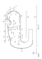
- FIG. 1 is a cross-sectional view of an engine 100 in accordance with an exemplary embodiment.
- the engine 100 is a multi-spool gas turbine main propulsion engine.
- the engine 100 includes an intake section 110, a compressor section 120, a combustion section 130, a turbine section 140, and an exhaust section 150
- the intake section 110 receives air drawn into the engine 100 and directs the air into the compressor section 120.
- the compressor section 120 may include one or more compressors that raise the pressure of the air and direct the compressed air into the combustion section 130. In the depicted embodiment, a two-stage compressor is shown, although it will be appreciated that one or more additional compressors could be used
- the combustion section 130 which is discussed in greater detail below, includes a combustor 160 that mixes the compressed air with fuel and ignites the resulting mixture to generate high energy combustion gases that are then directed into the turbine section 140.
- the combustor 160 is implemented as a reverse flow combustor unit, although other embodiments may include a different type of combustor.
- the turbine section 140 includes one or more turbines in which the combustion gases from the combustion section 130 expand and rotate the turbines. The combustion gases are then exhausted through the exhaust section 150.
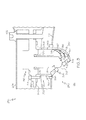
- FIG. 2 is a more detailed cross-sectional view of a portion of the engine 100 of FIG. 1 , and particularly illustrates the combustion section 130 of FIG. 1 .
- the combustor 160 may be an annular rich burn, quick quench, lean burn (RQL) reverse-flow gas turbine engine combustor, as will now be described in more detail.
- the combustor 160 may be another type of combustor.
- the combustor 160 includes a radially inner case 202 and a radially outer case 204 concentrically arranged with respect to the inner case 202.
- the inner and outer cases 202, 204 circumscribe the centerline 200 to define an annular pressure vessel 206.
- the combustor 160 is arranged within the annular pressure vessel 206.
- the combustor 160 includes an inner liner 210 and an outer liner 212 circumscribing the inner liner 210.
- the liners 210, 212 and cases 202, 204 define respective inner and outer air plenums 216, 218.
- the combustor 160 further includes a combustor dome 220 respectively coupled to inner and outer liners 210, 212 at a first (or inner) edge 224 and a second (or outer) edge 226.
- the inner liner 210, the outer liner 212, and the combustor dome 220 cooperate to form a combustion chamber 214 therebetween.
- the combustor 160 further includes a series of fuel injector assemblies 230 (one of which is shown) coupled to the outer liner 212. Quench air admission holes 240, 250 respectively formed in the inner and outer liners 210, 212, and dilution air admission holes 260, 270 also respectively formed in the inner and outer liners 210, 212.
- a portion of the pressurized air from the compressor section 120 enters a rich burn zone RB of the combustion chamber 214 in the inner and outer liners 210, 212.
- the pressurized air entering the rich burn zone RB is schematically shown in FIG. 2 as air flow 282, 286.
- the fuel injector assemblies 230 are arranged to supply fuel to the rich burn zone RB in a compound angular direction, which includes a radially inward direction toward the centerline 200, an axial direction toward the combustor dome 220, and a tangential direction about the circumference of the combustion chamber 214 to result in improved mixing of the fuel with the primary air jets 282, 286.
- the air flow 282, 286 intermixes with a stoichiometrically excessive quantity of fuel introduced through the fuel injector assemblies 230 to support initial combustion in the rich burn zone RB.
- the rich stoichiometry of the fuel-air mixture in the rich burn zone RB produces a relatively cool, oxygen-deprived flame, thus preventing excessive NOx formation and guarding against blowout of the combustion flame during any abrupt reduction in engine power.
- the combustor dome 220 may include a number of effusion holes 222 to permit compressed air to pass therethrough as a cooling flow on the interior surface of the combustor dome 220, which functions as a buffering layer to reduce the direct contact of the hot combustion gases 290 with interior surface of the combustor dome 220 as well as convectively cooling the wall of the combustor dome 220.
- the combustion gases 290 from the rich burn zone RB enter a quench zone Q.
- Quench jets 242, 252 flow from the plenums 216, 218 and into the quench zone Q through the quench air admission holes 240, 250 in the inner and outer liners 210, 212, respectively to rapidly mix the combustion gases 290 from a stoichiometrically rich state at the forward edge of the quench zone Q to a stoichiometrically lean state at, or just downstream of, the aft edge of the quench zone Q.
- thermal NOx formation is a strong time-at-temperature phenomenon, it is important that the fuel-rich mixture passing through the quench zone Q be mixed rapidly and thoroughly to a fuel-lean state in order to avoid excessive NOx generation.
- the combustion products from the quench zone Q enter a lean burn zone LB where the combustion process concludes.
- the quench jets 242, 252 are swept downstream and also continue to penetrate radially and spread out laterally to intermix thoroughly with the combustion gases 290.
- dilution jets 262, 272 flow from the plenums 216, 218 through dilution air admission holes 260, 270 respectively formed in the inner and outer liners 210, 212 to result in a stoichiometrically lean quantity of fuel in the lean burn zone LB.
- the dilution air admission holes 260, 270 additionally function to provide a desired temperature distribution and to complete the combustion process such that smoke and NOx emissions are reduced.
- RQL combustor is described above, exemplary embodiments discussed below may be incorporated into any type of combustor.
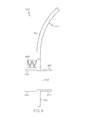
- FIG. 3 is a cross-sectional view of a fuel injector assembly (e.g., fuel injector assembly 230 of the combustor 160 of FIG. 2 ) in accordance with an exemplary embodiment.
- a number of fuel injector assemblies 230 may be angularly spaced about the annular combustor 160 of FIG. 2 .
- the fuel injector assembly 230 includes a fuel injector 310and a fuel injector shroud 330.
- the fuel injector 310 and fuel injector shroud 330 may be mounted in any suitable configuration and arrangement such that the fuel injector assembly 230 provides the desired fuel-air mixture to the combustion chamber 214.
- a ring or boss structure may be provided to couple the fuel injector 310 and/or the fuel injector shroud 330 the case 204 of the combustor 160, e.g., with a bolt of other mounting arrangement.
- the fuel injector 310 extends from the case 204 through an opening in combustion liner 212. As described in greater detail below, the fuel injector 310 includes a body 314 with a nozzle 316. The fuel injector 310 is configured to receive a flow of fuel from a manifold and/or fuel source (not shown) and the body 314 defines a passageway to direct the fuel to the nozzle 316. The nozzle 316 delivers fuel to the combustion chamber 214, which is mixed with air delivered by the fuel injector shroud 330.
- the body 314 of the fuel injector 310 extends in a generally radial direction, and the nozzle 316 is oriented at an angle to the body 314.
- the fuel injector 310 may include a flange 312 to provide a mounting arrangement.
- a cylindrical heat shield 320 may be provided to at least partially shield the body 314 and/or nozzle 316.
- the nozzle 316 is oriented in a partially axial or upstream direction toward the combustor dome 220 ( FIG. 2 ) such that the fuel is delivered at a compound angle, e.g., a partially axial and partially radial direction, as well as a tangential or circumferential direction, as desired.
- the nozzle 316 may be oriented in any suitable direction. Proper delivery of the fuel may promote blending and burn uniformity within rich burn zone RB of the combustion chamber 214, which may enhance the cooling characteristics, the NOx emissions characteristics, and the temperature distributions of the combustion gases entering the turbine section 140 ( FIG. 1 ).
- the fuel injector shroud 330 generally includes a mounting flange 340, a body portion 350, and a swirler device 370.
- the mounting flange 340 generally extends in an axial-circumferential plane, perpendicular to a radial direction.
- the mounting flange 340 extends from the body portion 350 and mounts the fuel injector shroud 330 to the fuel injector 310.
- the mounting flange 340 of the fuel injector shroud 330 and the flange 312 of the fuel injector 310 have corresponding holes for respectively receiving a screw or bolt 315 to secure the fuel injector assembly 230 together.
- different mounting arrangements may be provided.
- the fuel injector shroud 330 may be press-fit or snap-fit into a matching structure on the fuel injector 310.
- the body portion 350 of the fuel injector shroud 330 is generally cylindrical to house the fuel injector 310.
- the body portion 350 includes a cylindrical section 352 extending from the mounting flange 340 and a dome section 354 extending from the cylindrical section 352.
- the cylindrical section 352 defines an air inlet 356 for admitting air into the fuel injector shroud 330 and the fuel injector assembly 230.
- the air inlet 356 is oval shaped, although any suitable shape may be provided. Additional details about the air inlet 356 will be provided below.
- the dome section 354 at least partially houses the nozzle 316 of the fuel injector 310 and defines a swirler mount 358 oriented in the direction of the nozzle 316. As described in greater detail below, the swirler mount 358 is generally circular and receives the swirler device 370. In some embodiments, the dome section 354 only partially defines the swirler mount 358 such that the remaining portion of the swirler mount 358 is formed by the cylindrical section.
- the dome section 354 and/or cylindrical section 352 may include one or more interior ribs 560, 561 arranged on the interior surfaces. Two interior ribs 560, 561 are shown in FIG. 3 , although as discussed below, additional interior ribs may be provided. In general, the interior ribs 560, 561 may be sized and arranged to direct air as necessary or desired in a predictable manner to the swirler device 370. Additional details about the interior ribs 560, 561 will be provided below.
- the dome section 354 may include one or more cooling holes 367.
- the cooling holes 367 may be effusion cooling holes that permit a portion of the air flowing through the fuel injector shroud 330 to pass through to the exterior surface of the dome section 354. Such cooling air forms a layer of cooling air to shield the dome section 354 from combustion gases.
- the cooling holes 367 may additionally provide some convective cooling as the cooling air passes through the of the dome section 354.
- the cooling holes 367 are generally 0.01 to 0.04 inches in diameter, although the diameter may vary with application and may depend on factors such as the dimensions of the dome section 354, the temperature of the combustion gases, and the velocity of the cooling flow.
- cooling holes 367 may be uniformly spaced and/or patterned to provide desired cooling characteristics. Additional aspects of the cooling holes 367 will be discussed below.
- the cylindrical section 352 includes an outer mounting ring 368 extending around the periphery of the cylindrical section 352.
- the outer mounting ring 368 may be coupled to the combustor liner 212 to position a portion of the fuel injector assembly in the combustion chamber 214.
- the dome section 354 extends into the combustion chamber 214 and functions to at least partially shield the fuel injector 310 from combustion gases within the combustion chamber 214.
- the swirler device 370 is mounted within the swirler mount 358 in the body portion 350.
- the swirler device 370 is disk-shaped with a center opening 372 for accommodating the nozzle 316 of the fuel injector 310 adjacent to or within the center opening 372 such that fuel may be delivered through the center opening 372, out of the nozzle 316, and out of the fuel injector assembly 230.
- One or more swirler holes 374 are arranged around the center opening 372 to deliver air at or proximate to the nozzle 316.
- the swirler holes 374 may be oriented as necessary or desired to swirl the air flowing therethrough, e.g., in axial, radial, and tangential directions and at angles to the surface of the swirler device 370 to thereby impart a swirling motion.
- the swirler device 370 including the center opening 372 and swirler holes 374, may be integrally formed with the other components of the fuel injector shroud 330. Additional details about the fuel injector shroud 330 will be provided below.
- the air Upon flowing out of the swirler device 370, the air is conditioned to mix with the fuel to provide the desired air-fuel characteristics.
- all or a substantial amount of the fuel and air mixing occurs outside of the fuel injector shroud 330, e.g. just downstream or immediately adjacent to the swirler device 370.
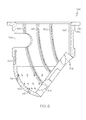
- FIGS. 4-8 depict various views of the fuel injector shroud 330 removed from the fuel injector assembly 230 of FIG. 3 .
- FIG. 4 is a first isometric exterior view of a fuel injector shroud 330
- FIG. 5 is a second isometric exterior view of the fuel injector shroud 330.
- FIGS. 4 and 5 particularly depict the mounting flange 340, the body portion 350, and the swirler device 370.
- FIG. 4 more clearly shows the arrangement of swirler holes 374 relative to the center opening 372 in the swirler device 370.
- FIG. 5 more clearly shows the air inlet 356 and the cooling holes 367 defined in the body portion 350.
- FIG. 6 is a cross-sectional view of the fuel injector shroud 330 of FIG. 4 through line 6-6 in accordance with an exemplary embodiment.
- FIG. 7 is a first isometric interior view of the fuel injector shroud 330 of FIGS. 4 and 5 in accordance with an exemplary embodiment.
- FIG. 7 is particularly a view into the interior of the fuel injector shroud 330, through the opening defined by the mounting flange 340.
- FIG. 8 is a cross-sectional view of the fuel injector shroud of FIG. 4 through line 8-8 in accordance with an exemplary embodiment.
- the air inlet 356 is generally oval and positioned on the cylindrical section 352.
- the air inlet 356 may have any suitable length, shape, size, or position to admit the desired amount of air into the fuel injector shroud 330.
- the air inlet 356 is positioned on the side of the cylindrical section on a side opposite to the swirler device 370 in an axial direction. The air flowing through the air inlet 356 enters the fuel injector shroud 330 in a generally axial direction and, as described below, is redirected towards the swirler device 370.
- FIGS. 6-8 particularly depict one exemplary arrangement of the interior ribs 560-569.
- the view of FIG. 6 depicts three interior ribs 560, 561, 562, while the view of FIGS. 7 and 8 depict ten interior ribs 560, 561, 562, 563, 564, 565, 566, 567, 568, 569.
- the interior ribs 560-569 may have any suitable shape, arrangement and number.
- the interior ribs 560-569 may be considered louvers or baffles.
- the interior ribs 560-569 are configured to direct air in an advantageous manner to the swirler device 370.
- the interior ribs 560-569 may direct air to the individual swirler holes 374 of the swirler device 370, thereby providing a more direct aerodynamic coupling between the air inlet 356 and the swirler holes 374.
- the interior ribs 560-569 from a first end, on the cylindrical section 352, along the concave length of the dome section 354 generally in the direction of air flow, to a second end, proximate to the swirler device 370.
- the ribs 560-569 extend from the edge or end of the cylindrical section 352, proximate to the mounting flange 340.
- the ribs 560-569 may extend from a radial position generally corresponding to the inlet 356, e.g. the inner radial edge of the inlet 356.
- the ribs 560-569 may be provided on the cylindrical section 352, the dome section 354, and/or a combination of the cylindrical section 352 and dome section 354, as necessary or desired to achieve advantageous airflow to the swirler device 370.
- the interior ribs 560-569 may have the same or different lengths and heights. In one exemplary embodiment, the interior ribs 560-569 may have heights, for example, of about 0.0100 inches to about 0. 250 inches, although other heights may be provided. As best shown in FIG. 7 , the second end of each interior rib 560-569 may be positioned between adjacent swirler holes 374. As such, adjacent interior ribs 560-569 may form a channel to more efficiently direct air into an individual swirler hole 374. In some embodiments, the interior ribs 560-569 may provide additional surface area to improve heat transfer characteristics, e.g., to improve thermal management of the shroud 330.
- the interior ribs 560-569 may have a longitudinal shape that is aerodynamic and/or curved such that air may be directed in the most desired manner. As best shown in FIG. 8 , the interior ribs 560-569 may have a triangular cross-sectional shape, although any shape may be provided, included rounded, frustum, conical and/or squared.
- the interior ribs 560-569 may function to provide a number of advantages.
- the interior ribs 560-569 may reduce flow losses through the fuel injector shroud 330.
- the interior ribs 560-569 may function to more evenly distribute the air flow to the swirler device 370.
- the air enters the fuel injector shroud 330 through in the air inlet 356 on an opposite side of the fuel injector shroud 330 from the swirler device 370, and the swirler device 370 is angled relative to the air inlet 356.
- interior ribs 560-569 may be arranged such that the air flow through each swirler hole 374 is approximately equal in flow rate, volume and/or velocity. The distribution may be managed based on any characteristic of the interior ribs 560-569, including number, height, shape, length, arrangement, position, and the like. These resulting channels formed by interior ribs 560-569 enable non-circular, vane-style flow passages that may result in improved combustor performance and emissions.
- the interior ribs 560-569 may be modified or augmented by a series of pins. Such pins may be sized and/or arranged to similarly direct a desired distribution of air flow to the swirler device 370, as well as provide additional surface area to improve heat transfer characteristics. Additionally, in some exemplary embodiments, the interior ribs 560-569 may be designed to suitably swirl the air along the interior surface of the fuel injector shroud 330. In such embodiments, the swirler device 370 may be omitted.
- the dome section 354 may have one or more cooling holes 367 that direct a portion of the air flowing through the fuel injector shroud 330 to pass through to the exterior surface of the dome section 354.
- the cooling holes 367 may be considered a first type of cooling hole that generally extends from an interior surface of the dome section 354, straight to the exterior surface of the dome section 354, typically at an angle to these surfaces.
- the dome section 354 may have other types of cooling holes.
- the dome section 354 may include one or more effusion cooling holes 600 formed by one or more segments extending at angles to one another. In the exemplary embodiment of FIG.
- the cooling hole 600 includes a first segment extending from the interior surface of the dome section 354, generally perpendicular to the interior surface, a second segment extending from the first segment at an angle, and a third segment extending from the second segment at an angle to the exterior surface of the dome section. 354.
- the cooling holes such as cooling hole 600, are not necessarily straight cooling holes and may extend along portions of the wall of the dome section 354 such that air may be taken from desired portions of the interior surface of the dome section 354 and delivered to desired portions of the exterior surface of the dome section 354, e.g., to improve the resulting layer of effusion cooling on the exterior surface.
- the cooling hole 600 considering the extended length to diameter ratio, may provide convective and conductive cooling to the dome section 354.
- an additional type of cooling hole 800 may be provided through the dome section 354.
- the dome section 354 may include cooling holes 800 that extend through the interior ribs 560-569.
- a cooling hole 800 extends through interior rib 560, through the wall of the dome section 354, and to the exterior surface of the dome section 354, and a cooling hole 800 extends through interior rib 565, through the wall of the dome section 354, and to the exterior surface of the dome surface 354.
- the cooling holes 800 may have any orientation through the cooling ribs 560-569.
- the cooling hole 800 through the interior rib 560 extends through the apex of the interior rib 560, generally through the center of the interior rib 560, and the cooling hole 800 extends at an angle through the interior rib 565.
- the cooling holes 800 may be effusion cooling holes that provide a layer of cooling air on the exterior surface of the dome section 354 to shield the dome section 354 from the combustion gases.
- the cooling hole 800 considering the extended length to diameter ratio, may provide convective and conductive cooling to the dome section 354.
- the cooling holes may minimize the amount of cooling air required and/or allow the usage of larger effusion hole diameters, thereby mitigating or eliminating potential blockages.
- the cooling hole e.g., cooling holes 600, 800
- FIG. 9 is a partial cross-sectional view of a fuel injector shroud 930 in accordance with an alternate exemplary embodiment. Unless otherwise noted, the fuel injector shroud 930 may have similar features to the fuel injector shroud 330 discussed above.
- FIG. 9 particularly depicts a portion of one side of the body portion 950 of the fuel injector shroud 930, including a portion of the cylindrical section 952, dome section 954, and air inlet 956.
- the air inlet 956 extends through the cylindrical section 952.
- the air inlet 956 includes a flange or bell mouth 900 on one or both of the radial sides of the air inlet 956, extending in an axial direction into the fuel injector shroud 930.
- the bell mouth 900 may be arranged and sized to direct the desired amount of air into the fuel injector shroud 930.
- an additional flange or bell mouth 902 may be provided on one or both of the radial sides of the air inlet 956, extending away from the air inlet 956. Similar to bell mouth 900, the bell mouth 902 may be arranged and sized to direct the desired amount of air into the fuel injector shroud 930. Although the bell mouth 900 and bell mouth 902 are straight in the axial direction, the bell mouth 900 and bell mouth 902 may be contoured as necessary or desired. The bell mouth 900 and/or bell mouth 902 may, in effect, extend the length of the air inlet 956 to improve the flow coefficient (Cd). Improved flow through the air inlet 956 may enable a smaller air inlet and/or a smaller diameter shroud with the corresponding lower weight and stress.
- Cd flow coefficient
- the exemplary embodiment of FIG. 9 additionally includes an outer mounting ring 968 for mounting the fuel injector shroud 930 to the combustor liner (not shown).
- the outer mounting ring 968 includes a bellows or corrugated structure.
- the outer mounting ring 968 is at least partially flexible, particularly in the axial-circumferential plane. Accordingly, the outer mounting ring 968 may accommodate relative movement between the fuel injector shroud 930 and the combustor liner resulting, for example, from different temperatures, different rates of thermal expansion, and relative movement of the various components coupled to the combustor liner and fuel injector shroud 930.
- the flexible outer mounting ring 968 may absorb some of the load resulting from thermal differences instead of transferring load to the fuel injector shroud 930, thereby enhancing load bearing capacity of the fuel injector shroud 930 without the need for separate combustor support pins or increased shroud size. Additionally, as a result of this more compliant sealing arrangement, leaks between the fuel injector shroud 930 and combustor liner may be mitigated or eliminated.
- FIG. 10 is a flow chart depicting a method 1000 of manufacturing a fuel injector shroud (e.g., fuel injector shroud 330, 930) in accordance with an exemplary embodiment.
- the fuel injector shroud is manufactured as a unitary structure.
- the term "unitary" is used in this application to denote that the associated component is made as a single piece during manufacturing.
- a unitary component has a monolithic construction for the entire component, and is different from a component that has been made from a plurality of component pieces that have been joined together to form a single component.
- portions of the fuel injector shroud, such as the swirler device may be manufactured separately and welded or brazed into the other components of the fuel injector shroud.
- a model such as a design model, of the fuel injector shroud may be defined in any suitable manner.
- the model may be designed with computer aided design (CAD) software.
- the model may include 3D numeric coordinates of the entire configuration of the component including both external and internal surfaces of an fuel injector shroud, as well as any internal channels and openings.
- the model may include a number of successive 2D cross-sectional slices that together form the 3D component.
- a first intermediate fuel injector shroud article is produced according to the model of step 1010 using a rapid prototyping or additive layer manufacturing process.
- Additive manufacturing (AM) processes fabricate components having relatively complex three dimensional geometries, including components with internal surfaces defining internal passages including internal hollow areas, internal channels, internal openings or the like for cooling, weight reduction, or otherwise.
- additive Manufacturing is defined by the American Society for Testing and Materials (ASTM) as the "process of joining materials to make objects from 3D model data, usually layer upon layer, as opposed to subtractive manufacturing methodologies, such as traditional machining and casting.”
- ASTM American Society for Testing and Materials
- Some examples of additive layer manufacturing processes include: micro-pen deposition in which liquid media is dispensed with precision at the pen tip and then cured; selective laser sintering in which a laser is used to sinter a powder media in precisely controlled locations; laser wire deposition in which a wire feedstock is melted by a laser and then deposited and solidified in precise locations to build the product; electron beam melting; laser engineered net shaping; and direct metal deposition.
- additive manufacturing techniques provide flexibility in free-form fabrication without geometric constraints, fast material processing time, and innovative joining techniques.
- DMLS/DMLF direct metal laser sintering (or fusing)
- DMLS/DMLF direct metal laser sintering
- DMLF direct metal laser sintering
- the first intermediate fuel injector shroud article may be formed within a build device containing powdered build material such that individual layers are formed by a laser fusing, subsequently lowered on a vertical device, additional build material is deposited on the previously formed layer, the subsequent layer is formed, and the process is repeated until the first intermediate fuel injector shroud article is completed.
- the build material may be formed by any suitable powder, including metal powders, such as a stainless steel powder, and alloys and super alloy materials, such as nickel-based or cobalt superalloys.
- the build material is a high temperature nickel base super alloy such as MAR-M-247.
- IN718 or IN738 or other suitable alloys may be employed.
- the powder build material may be selected for enhanced strength, durability, and useful life, particularly at high temperatures.
- a second intermediate fuel injector shroud article is produced by encapsulating the first intermediate fuel injector shroud article with an encapsulation layer.
- the encapsulation layer may functions to effectively convert any surface porosity and cracks into internal porosity and cracks. Any suitable encapsulation process may be provided that bridges and covers the porosity and cracks in the surface.
- the encapsulation layer may have a thickness of approximately 10-100 ⁇ m, although any suitable thickness may be provided.
- the encapsulation layer may be a metal or alloy that is compatible with the substrate and may be applied by a plating or coating process.
- a third intermediate fuel injector shroud article is produced by a consolidation process, such as a hot isostatic pressing (HIP) process in which the second intermediate fuel injector shroud article is subjected to elevated temperatures and pressures over time.
- the HIP process may be performed at any temperature, pressure, and time that are suitable for forming a compacted solid having negligible porosity.
- the HIP process may be performed at a processing temperature in a range of about 1000° C. to about 1300° C. and may be performed at a pressure in a range of about 1 ksi to about 25 ksi for a time period of about 1 to about 10 hours.
- the HIP processing temperature, pressure, and time may be smaller or larger.
- the fuel injector shroud is produced by applying one or more finishing treatments to the third intermediate fuel injector shroud article.
- the finishing treatments may include, for example, additional heat, aging, annealing, quenching, or surface treatments.
- An additional finishing step 1050 may include machining, including machining to the final specifications and/or formation of cooling holes.
- the cooling holes and other aspects that are typically formed by machining may be directly formed in the additive manufacturing process described above.
- the fuel injector shroud corresponds to the completed fuel injector shroud and may be positioned for its intended use, such as installed in the combustor of FIG. 2 .
- TBC fuel injector shrouds.
- Embodiments discussed herein may find beneficial use in many industries and applications, including aerospace, automotive, and electricity generation.
Landscapes
- Engineering & Computer Science (AREA)
- Mechanical Engineering (AREA)
- Chemical & Material Sciences (AREA)
- Combustion & Propulsion (AREA)
- General Engineering & Computer Science (AREA)
- Physics & Mathematics (AREA)
- Optics & Photonics (AREA)
- Plasma & Fusion (AREA)
- Manufacturing & Machinery (AREA)
- Materials Engineering (AREA)
- Turbine Rotor Nozzle Sealing (AREA)
Applications Claiming Priority (1)
| Application Number | Priority Date | Filing Date | Title |
|---|---|---|---|
| US14/067,377 US9625156B2 (en) | 2013-10-30 | 2013-10-30 | Gas turbine engines having fuel injector shrouds with interior ribs |
Publications (2)
| Publication Number | Publication Date |
|---|---|
| EP2868973A1 true EP2868973A1 (de) | 2015-05-06 |
| EP2868973B1 EP2868973B1 (de) | 2018-12-12 |
Family
ID=51663040
Family Applications (1)
| Application Number | Title | Priority Date | Filing Date |
|---|---|---|---|
| EP14187575.7A Active EP2868973B1 (de) | 2013-10-30 | 2014-10-02 | Gasturbinenmotoren mit Kraftstoffinjektorummantelungen mit inneren Rippen |
Country Status (2)
| Country | Link |
|---|---|
| US (1) | US9625156B2 (de) |
| EP (1) | EP2868973B1 (de) |
Cited By (1)
| Publication number | Priority date | Publication date | Assignee | Title |
|---|---|---|---|---|
| EP4715264A1 (de) * | 2024-09-24 | 2026-03-25 | Honeywell International Inc. | Kühlung der abdeckung eines gasturbinenmotorbrennstoffzerstäubers |
Families Citing this family (20)
| Publication number | Priority date | Publication date | Assignee | Title |
|---|---|---|---|---|
| US10145559B2 (en) | 2015-12-15 | 2018-12-04 | General Electric Company | Gas turbine engine with igniter stack or borescope mount having noncollinear cooling passages |
| US10232469B2 (en) * | 2016-09-30 | 2019-03-19 | Caterpillar Inc. | System and method for manufacturing component |
| GB201701380D0 (en) * | 2016-12-20 | 2017-03-15 | Rolls Royce Plc | A combustion chamber and a combustion chamber fuel injector seal |
| KR101872801B1 (ko) * | 2017-04-18 | 2018-06-29 | 두산중공업 주식회사 | 연료노즐 조립체 및 이를 포함하는 가스터빈 |
| WO2019012559A1 (en) * | 2017-07-12 | 2019-01-17 | Bharat Forge Limited | ADDITIVE FABRICATION PROCESS FOR COMBUSTION CHAMBER |
| US11060479B2 (en) | 2017-08-29 | 2021-07-13 | General Electric Company | Reciprocating engine |
| US10976052B2 (en) | 2017-10-25 | 2021-04-13 | General Electric Company | Volute trapped vortex combustor assembly |
| US10976053B2 (en) | 2017-10-25 | 2021-04-13 | General Electric Company | Involute trapped vortex combustor assembly |
| US11175045B2 (en) | 2018-01-04 | 2021-11-16 | General Electric Company | Fuel nozzle for gas turbine engine combustor |
| US11426818B2 (en) | 2018-08-10 | 2022-08-30 | The Research Foundation for the State University | Additive manufacturing processes and additively manufactured products |
| US11181269B2 (en) | 2018-11-15 | 2021-11-23 | General Electric Company | Involute trapped vortex combustor assembly |
| US11549437B2 (en) * | 2021-02-18 | 2023-01-10 | Honeywell International Inc. | Combustor for gas turbine engine and method of manufacture |
| US11701625B2 (en) * | 2021-05-05 | 2023-07-18 | Gideon Vandegrift | Multiple-Venturi nozzle, system, method of manufacture and method of use |
| US11859819B2 (en) | 2021-10-15 | 2024-01-02 | General Electric Company | Ceramic composite combustor dome and liners |
| US11988386B2 (en) * | 2021-12-03 | 2024-05-21 | Honeywell International Inc. | Gas turbine engine injector module with thermally coupled fuel lines having respective outlets |
| CN117091159A (zh) | 2022-05-13 | 2023-11-21 | 通用电气公司 | 燃烧器衬里 |
| CN117091161A (zh) | 2022-05-13 | 2023-11-21 | 通用电气公司 | 燃烧器衬里的中空板设计和结构 |
| CN117091157A (zh) | 2022-05-13 | 2023-11-21 | 通用电气公司 | 用于耐用燃烧室衬里的板吊架结构 |
| CN117091162B (zh) | 2022-05-13 | 2026-03-27 | 通用电气公司 | 具有稀释孔结构的燃烧器 |
| CN117091158B (zh) | 2022-05-13 | 2026-03-06 | 通用电气公司 | 燃烧器室网状结构 |
Citations (4)
| Publication number | Priority date | Publication date | Assignee | Title |
|---|---|---|---|---|
| US4082499A (en) * | 1976-11-12 | 1978-04-04 | Allis-Chalmers Corporation | Multipurpose kiln shell gas burner |
| WO1994028351A1 (en) * | 1993-06-01 | 1994-12-08 | Pratt & Whitney Canada, Inc. | Radially mounted air blast fuel injector |
| US20070012042A1 (en) * | 2005-07-18 | 2007-01-18 | Pratt & Whitney Canada Corp. | Low smoke and emissions fuel nozzle |
| US20070193272A1 (en) * | 2006-02-21 | 2007-08-23 | Woodward Fst, Inc. | Gas turbine engine fuel injector |
Family Cites Families (5)
| Publication number | Priority date | Publication date | Assignee | Title |
|---|---|---|---|---|
| US8196845B2 (en) * | 2007-09-17 | 2012-06-12 | Delavan Inc | Flexure seal for fuel injection nozzle |
| US20090255256A1 (en) | 2008-04-11 | 2009-10-15 | General Electric Company | Method of manufacturing combustor components |
| US8161751B2 (en) | 2009-04-30 | 2012-04-24 | General Electric Company | High volume fuel nozzles for a turbine engine |
| FR2971039B1 (fr) * | 2011-02-02 | 2013-01-11 | Turbomeca | Injecteur de chambre de combustion de turbine a gaz a double circuit de carburant et chambre de combustion equipee d'au moins un tel injecteur |
| CA2900654C (en) * | 2013-03-07 | 2020-03-31 | Rolls-Royce Corporation | Flexible bellows igniter seal for a gas turbine with a ceramic combustion liner |
-
2013
- 2013-10-30 US US14/067,377 patent/US9625156B2/en active Active
-
2014
- 2014-10-02 EP EP14187575.7A patent/EP2868973B1/de active Active
Patent Citations (4)
| Publication number | Priority date | Publication date | Assignee | Title |
|---|---|---|---|---|
| US4082499A (en) * | 1976-11-12 | 1978-04-04 | Allis-Chalmers Corporation | Multipurpose kiln shell gas burner |
| WO1994028351A1 (en) * | 1993-06-01 | 1994-12-08 | Pratt & Whitney Canada, Inc. | Radially mounted air blast fuel injector |
| US20070012042A1 (en) * | 2005-07-18 | 2007-01-18 | Pratt & Whitney Canada Corp. | Low smoke and emissions fuel nozzle |
| US20070193272A1 (en) * | 2006-02-21 | 2007-08-23 | Woodward Fst, Inc. | Gas turbine engine fuel injector |
Cited By (1)
| Publication number | Priority date | Publication date | Assignee | Title |
|---|---|---|---|---|
| EP4715264A1 (de) * | 2024-09-24 | 2026-03-25 | Honeywell International Inc. | Kühlung der abdeckung eines gasturbinenmotorbrennstoffzerstäubers |
Also Published As
| Publication number | Publication date |
|---|---|
| US20150113993A1 (en) | 2015-04-30 |
| US9625156B2 (en) | 2017-04-18 |
| EP2868973B1 (de) | 2018-12-12 |
Similar Documents
| Publication | Publication Date | Title |
|---|---|---|
| US9625156B2 (en) | Gas turbine engines having fuel injector shrouds with interior ribs | |
| US9765968B2 (en) | Combustors with complex shaped effusion holes | |
| US9410702B2 (en) | Gas turbine engine combustors with effusion and impingement cooling and methods for manufacturing the same using additive manufacturing techniques | |
| US8061142B2 (en) | Mixer for a combustor | |
| US11519604B2 (en) | Plug resistant effusion holes for gas turbine engine | |
| US9574533B2 (en) | Fuel injection nozzle and method of manufacturing the same | |
| US9739161B2 (en) | Vaned structure and a method of manufacturing a vaned structure | |
| EP3771864B1 (de) | Dualbrennstofflanze mit kühlmikrokanälen | |
| US11549437B2 (en) | Combustor for gas turbine engine and method of manufacture | |
| EP3176505B1 (de) | Kraftstoffeinspritzventil und herstellungsmethode | |
| WO2009126403A2 (en) | Swirlers and method of manufacturing | |
| EP4089265A1 (de) | Beschichtung von verstopfungsresistenten effusionskühlungslöchern für gasturbinenmotoren | |
| EP3974725B1 (de) | Kraftstoffeinspritzungsanordnung für eine turbomaschine | |
| US20250244016A1 (en) | Turbomachine having improved mixing tube elements |
Legal Events
| Date | Code | Title | Description |
|---|---|---|---|
| PUAI | Public reference made under article 153(3) epc to a published international application that has entered the european phase |
Free format text: ORIGINAL CODE: 0009012 |
|
| 17P | Request for examination filed |
Effective date: 20141002 |
|
| AK | Designated contracting states |
Kind code of ref document: A1 Designated state(s): AL AT BE BG CH CY CZ DE DK EE ES FI FR GB GR HR HU IE IS IT LI LT LU LV MC MK MT NL NO PL PT RO RS SE SI SK SM TR |
|
| AX | Request for extension of the european patent |
Extension state: BA ME |
|
| RAP1 | Party data changed (applicant data changed or rights of an application transferred) |
Owner name: HONEYWELL INTERNATIONAL INC. |
|
| GRAP | Despatch of communication of intention to grant a patent |
Free format text: ORIGINAL CODE: EPIDOSNIGR1 |
|
| STAA | Information on the status of an ep patent application or granted ep patent |
Free format text: STATUS: GRANT OF PATENT IS INTENDED |
|
| INTG | Intention to grant announced |
Effective date: 20180621 |
|
| GRAS | Grant fee paid |
Free format text: ORIGINAL CODE: EPIDOSNIGR3 |
|
| GRAA | (expected) grant |
Free format text: ORIGINAL CODE: 0009210 |
|
| STAA | Information on the status of an ep patent application or granted ep patent |
Free format text: STATUS: THE PATENT HAS BEEN GRANTED |
|
| AK | Designated contracting states |
Kind code of ref document: B1 Designated state(s): AL AT BE BG CH CY CZ DE DK EE ES FI FR GB GR HR HU IE IS IT LI LT LU LV MC MK MT NL NO PL PT RO RS SE SI SK SM TR |
|
| REG | Reference to a national code |
Ref country code: GB Ref legal event code: FG4D |
|
| REG | Reference to a national code |
Ref country code: CH Ref legal event code: EP |
|
| REG | Reference to a national code |
Ref country code: AT Ref legal event code: REF Ref document number: 1076533 Country of ref document: AT Kind code of ref document: T Effective date: 20181215 |
|
| REG | Reference to a national code |
Ref country code: DE Ref legal event code: R096 Ref document number: 602014037750 Country of ref document: DE |
|
| REG | Reference to a national code |
Ref country code: IE Ref legal event code: FG4D |
|
| REG | Reference to a national code |
Ref country code: NL Ref legal event code: MP Effective date: 20181212 |
|
| REG | Reference to a national code |
Ref country code: LT Ref legal event code: MG4D |
|
| PG25 | Lapsed in a contracting state [announced via postgrant information from national office to epo] |
Ref country code: LT Free format text: LAPSE BECAUSE OF FAILURE TO SUBMIT A TRANSLATION OF THE DESCRIPTION OR TO PAY THE FEE WITHIN THE PRESCRIBED TIME-LIMIT Effective date: 20181212 Ref country code: HR Free format text: LAPSE BECAUSE OF FAILURE TO SUBMIT A TRANSLATION OF THE DESCRIPTION OR TO PAY THE FEE WITHIN THE PRESCRIBED TIME-LIMIT Effective date: 20181212 Ref country code: NO Free format text: LAPSE BECAUSE OF FAILURE TO SUBMIT A TRANSLATION OF THE DESCRIPTION OR TO PAY THE FEE WITHIN THE PRESCRIBED TIME-LIMIT Effective date: 20190312 Ref country code: BG Free format text: LAPSE BECAUSE OF FAILURE TO SUBMIT A TRANSLATION OF THE DESCRIPTION OR TO PAY THE FEE WITHIN THE PRESCRIBED TIME-LIMIT Effective date: 20190312 Ref country code: FI Free format text: LAPSE BECAUSE OF FAILURE TO SUBMIT A TRANSLATION OF THE DESCRIPTION OR TO PAY THE FEE WITHIN THE PRESCRIBED TIME-LIMIT Effective date: 20181212 Ref country code: LV Free format text: LAPSE BECAUSE OF FAILURE TO SUBMIT A TRANSLATION OF THE DESCRIPTION OR TO PAY THE FEE WITHIN THE PRESCRIBED TIME-LIMIT Effective date: 20181212 Ref country code: ES Free format text: LAPSE BECAUSE OF FAILURE TO SUBMIT A TRANSLATION OF THE DESCRIPTION OR TO PAY THE FEE WITHIN THE PRESCRIBED TIME-LIMIT Effective date: 20181212 |
|
| REG | Reference to a national code |
Ref country code: AT Ref legal event code: MK05 Ref document number: 1076533 Country of ref document: AT Kind code of ref document: T Effective date: 20181212 |
|
| PG25 | Lapsed in a contracting state [announced via postgrant information from national office to epo] |
Ref country code: RS Free format text: LAPSE BECAUSE OF FAILURE TO SUBMIT A TRANSLATION OF THE DESCRIPTION OR TO PAY THE FEE WITHIN THE PRESCRIBED TIME-LIMIT Effective date: 20181212 Ref country code: GR Free format text: LAPSE BECAUSE OF FAILURE TO SUBMIT A TRANSLATION OF THE DESCRIPTION OR TO PAY THE FEE WITHIN THE PRESCRIBED TIME-LIMIT Effective date: 20190313 Ref country code: SE Free format text: LAPSE BECAUSE OF FAILURE TO SUBMIT A TRANSLATION OF THE DESCRIPTION OR TO PAY THE FEE WITHIN THE PRESCRIBED TIME-LIMIT Effective date: 20181212 Ref country code: AL Free format text: LAPSE BECAUSE OF FAILURE TO SUBMIT A TRANSLATION OF THE DESCRIPTION OR TO PAY THE FEE WITHIN THE PRESCRIBED TIME-LIMIT Effective date: 20181212 |
|
| PG25 | Lapsed in a contracting state [announced via postgrant information from national office to epo] |
Ref country code: NL Free format text: LAPSE BECAUSE OF FAILURE TO SUBMIT A TRANSLATION OF THE DESCRIPTION OR TO PAY THE FEE WITHIN THE PRESCRIBED TIME-LIMIT Effective date: 20181212 |
|
| PG25 | Lapsed in a contracting state [announced via postgrant information from national office to epo] |
Ref country code: PL Free format text: LAPSE BECAUSE OF FAILURE TO SUBMIT A TRANSLATION OF THE DESCRIPTION OR TO PAY THE FEE WITHIN THE PRESCRIBED TIME-LIMIT Effective date: 20181212 Ref country code: IT Free format text: LAPSE BECAUSE OF FAILURE TO SUBMIT A TRANSLATION OF THE DESCRIPTION OR TO PAY THE FEE WITHIN THE PRESCRIBED TIME-LIMIT Effective date: 20181212 Ref country code: PT Free format text: LAPSE BECAUSE OF FAILURE TO SUBMIT A TRANSLATION OF THE DESCRIPTION OR TO PAY THE FEE WITHIN THE PRESCRIBED TIME-LIMIT Effective date: 20190412 Ref country code: CZ Free format text: LAPSE BECAUSE OF FAILURE TO SUBMIT A TRANSLATION OF THE DESCRIPTION OR TO PAY THE FEE WITHIN THE PRESCRIBED TIME-LIMIT Effective date: 20181212 |
|
| PG25 | Lapsed in a contracting state [announced via postgrant information from national office to epo] |
Ref country code: SK Free format text: LAPSE BECAUSE OF FAILURE TO SUBMIT A TRANSLATION OF THE DESCRIPTION OR TO PAY THE FEE WITHIN THE PRESCRIBED TIME-LIMIT Effective date: 20181212 Ref country code: SM Free format text: LAPSE BECAUSE OF FAILURE TO SUBMIT A TRANSLATION OF THE DESCRIPTION OR TO PAY THE FEE WITHIN THE PRESCRIBED TIME-LIMIT Effective date: 20181212 Ref country code: RO Free format text: LAPSE BECAUSE OF FAILURE TO SUBMIT A TRANSLATION OF THE DESCRIPTION OR TO PAY THE FEE WITHIN THE PRESCRIBED TIME-LIMIT Effective date: 20181212 Ref country code: IS Free format text: LAPSE BECAUSE OF FAILURE TO SUBMIT A TRANSLATION OF THE DESCRIPTION OR TO PAY THE FEE WITHIN THE PRESCRIBED TIME-LIMIT Effective date: 20190412 Ref country code: EE Free format text: LAPSE BECAUSE OF FAILURE TO SUBMIT A TRANSLATION OF THE DESCRIPTION OR TO PAY THE FEE WITHIN THE PRESCRIBED TIME-LIMIT Effective date: 20181212 |
|
| REG | Reference to a national code |
Ref country code: DE Ref legal event code: R097 Ref document number: 602014037750 Country of ref document: DE |
|
| PLBE | No opposition filed within time limit |
Free format text: ORIGINAL CODE: 0009261 |
|
| STAA | Information on the status of an ep patent application or granted ep patent |
Free format text: STATUS: NO OPPOSITION FILED WITHIN TIME LIMIT |
|
| PG25 | Lapsed in a contracting state [announced via postgrant information from national office to epo] |
Ref country code: AT Free format text: LAPSE BECAUSE OF FAILURE TO SUBMIT A TRANSLATION OF THE DESCRIPTION OR TO PAY THE FEE WITHIN THE PRESCRIBED TIME-LIMIT Effective date: 20181212 Ref country code: SI Free format text: LAPSE BECAUSE OF FAILURE TO SUBMIT A TRANSLATION OF THE DESCRIPTION OR TO PAY THE FEE WITHIN THE PRESCRIBED TIME-LIMIT Effective date: 20181212 Ref country code: DK Free format text: LAPSE BECAUSE OF FAILURE TO SUBMIT A TRANSLATION OF THE DESCRIPTION OR TO PAY THE FEE WITHIN THE PRESCRIBED TIME-LIMIT Effective date: 20181212 |
|
| 26N | No opposition filed |
Effective date: 20190913 |
|
| PG25 | Lapsed in a contracting state [announced via postgrant information from national office to epo] |
Ref country code: TR Free format text: LAPSE BECAUSE OF FAILURE TO SUBMIT A TRANSLATION OF THE DESCRIPTION OR TO PAY THE FEE WITHIN THE PRESCRIBED TIME-LIMIT Effective date: 20181212 |
|
| PG25 | Lapsed in a contracting state [announced via postgrant information from national office to epo] |
Ref country code: MC Free format text: LAPSE BECAUSE OF FAILURE TO SUBMIT A TRANSLATION OF THE DESCRIPTION OR TO PAY THE FEE WITHIN THE PRESCRIBED TIME-LIMIT Effective date: 20181212 |
|
| REG | Reference to a national code |
Ref country code: CH Ref legal event code: PL |
|
| PG25 | Lapsed in a contracting state [announced via postgrant information from national office to epo] |
Ref country code: LU Free format text: LAPSE BECAUSE OF NON-PAYMENT OF DUE FEES Effective date: 20191002 Ref country code: LI Free format text: LAPSE BECAUSE OF NON-PAYMENT OF DUE FEES Effective date: 20191031 Ref country code: CH Free format text: LAPSE BECAUSE OF NON-PAYMENT OF DUE FEES Effective date: 20191031 |
|
| REG | Reference to a national code |
Ref country code: BE Ref legal event code: MM Effective date: 20191031 |
|
| PG25 | Lapsed in a contracting state [announced via postgrant information from national office to epo] |
Ref country code: BE Free format text: LAPSE BECAUSE OF NON-PAYMENT OF DUE FEES Effective date: 20191031 |
|
| GBPC | Gb: european patent ceased through non-payment of renewal fee |
Effective date: 20191002 |
|
| PG25 | Lapsed in a contracting state [announced via postgrant information from national office to epo] |
Ref country code: GB Free format text: LAPSE BECAUSE OF NON-PAYMENT OF DUE FEES Effective date: 20191002 Ref country code: IE Free format text: LAPSE BECAUSE OF NON-PAYMENT OF DUE FEES Effective date: 20191002 Ref country code: FR Free format text: LAPSE BECAUSE OF NON-PAYMENT OF DUE FEES Effective date: 20191031 |
|
| PG25 | Lapsed in a contracting state [announced via postgrant information from national office to epo] |
Ref country code: CY Free format text: LAPSE BECAUSE OF FAILURE TO SUBMIT A TRANSLATION OF THE DESCRIPTION OR TO PAY THE FEE WITHIN THE PRESCRIBED TIME-LIMIT Effective date: 20181212 |
|
| PG25 | Lapsed in a contracting state [announced via postgrant information from national office to epo] |
Ref country code: HU Free format text: LAPSE BECAUSE OF FAILURE TO SUBMIT A TRANSLATION OF THE DESCRIPTION OR TO PAY THE FEE WITHIN THE PRESCRIBED TIME-LIMIT; INVALID AB INITIO Effective date: 20141002 Ref country code: MT Free format text: LAPSE BECAUSE OF FAILURE TO SUBMIT A TRANSLATION OF THE DESCRIPTION OR TO PAY THE FEE WITHIN THE PRESCRIBED TIME-LIMIT Effective date: 20181212 |
|
| PG25 | Lapsed in a contracting state [announced via postgrant information from national office to epo] |
Ref country code: MK Free format text: LAPSE BECAUSE OF FAILURE TO SUBMIT A TRANSLATION OF THE DESCRIPTION OR TO PAY THE FEE WITHIN THE PRESCRIBED TIME-LIMIT Effective date: 20181212 |
|
| P01 | Opt-out of the competence of the unified patent court (upc) registered |
Effective date: 20230525 |
|
| PGFP | Annual fee paid to national office [announced via postgrant information from national office to epo] |
Ref country code: DE Payment date: 20251028 Year of fee payment: 12 |