EP2869094B1 - Stereoskopische Abbildungssysteme und Verfahren - Google Patents
Stereoskopische Abbildungssysteme und Verfahren Download PDFInfo
- Publication number
- EP2869094B1 EP2869094B1 EP14190459.9A EP14190459A EP2869094B1 EP 2869094 B1 EP2869094 B1 EP 2869094B1 EP 14190459 A EP14190459 A EP 14190459A EP 2869094 B1 EP2869094 B1 EP 2869094B1
- Authority
- EP
- European Patent Office
- Prior art keywords
- ray
- depth information
- images
- point
- image
- Prior art date
- Legal status (The legal status is an assumption and is not a legal conclusion. Google has not performed a legal analysis and makes no representation as to the accuracy of the status listed.)
- Active
Links
Images


Classifications
-
- G—PHYSICS
- G01—MEASURING; TESTING
- G01V—GEOPHYSICS; GRAVITATIONAL MEASUREMENTS; DETECTING MASSES OR OBJECTS; TAGS
- G01V5/00—Prospecting or detecting by the use of ionising radiation, e.g. of natural or induced radioactivity
- G01V5/20—Detecting prohibited goods, e.g. weapons, explosives, hazardous substances, contraband or smuggled objects
- G01V5/22—Active interrogation, i.e. by irradiating objects or goods using external radiation sources, e.g. using gamma rays or cosmic rays
- G01V5/228—Active interrogation, i.e. by irradiating objects or goods using external radiation sources, e.g. using gamma rays or cosmic rays using stereoscopic means
-
- A—HUMAN NECESSITIES
- A61—MEDICAL OR VETERINARY SCIENCE; HYGIENE
- A61B—DIAGNOSIS; SURGERY; IDENTIFICATION
- A61B6/00—Apparatus or devices for radiation diagnosis; Apparatus or devices for radiation diagnosis combined with radiation therapy equipment
- A61B6/02—Arrangements for diagnosis sequentially in different planes; Stereoscopic radiation diagnosis
- A61B6/022—Stereoscopic imaging
-
- A—HUMAN NECESSITIES
- A61—MEDICAL OR VETERINARY SCIENCE; HYGIENE
- A61B—DIAGNOSIS; SURGERY; IDENTIFICATION
- A61B6/00—Apparatus or devices for radiation diagnosis; Apparatus or devices for radiation diagnosis combined with radiation therapy equipment
- A61B6/42—Arrangements for detecting radiation specially adapted for radiation diagnosis
- A61B6/4266—Arrangements for detecting radiation specially adapted for radiation diagnosis characterised by using a plurality of detector units
-
- G—PHYSICS
- G06—COMPUTING OR CALCULATING; COUNTING
- G06T—IMAGE DATA PROCESSING OR GENERATION, IN GENERAL
- G06T15/00—Three-dimensional [3D] image rendering
- G06T15/06—Ray-tracing
-
- G—PHYSICS
- G06—COMPUTING OR CALCULATING; COUNTING
- G06T—IMAGE DATA PROCESSING OR GENERATION, IN GENERAL
- G06T15/00—Three-dimensional [3D] image rendering
- G06T15/08—Volume rendering
-
- G—PHYSICS
- G06—COMPUTING OR CALCULATING; COUNTING
- G06T—IMAGE DATA PROCESSING OR GENERATION, IN GENERAL
- G06T19/00—Manipulating three-dimensional [3D] models or images for computer graphics
- G06T19/006—Mixed reality
-
- H—ELECTRICITY
- H04—ELECTRIC COMMUNICATION TECHNIQUE
- H04N—PICTORIAL COMMUNICATION, e.g. TELEVISION
- H04N13/00—Stereoscopic video systems; Multi-view video systems; Details thereof
- H04N13/10—Processing, recording or transmission of stereoscopic or multi-view image signals
- H04N13/106—Processing image signals
-
- G—PHYSICS
- G06—COMPUTING OR CALCULATING; COUNTING
- G06T—IMAGE DATA PROCESSING OR GENERATION, IN GENERAL
- G06T2207/00—Indexing scheme for image analysis or image enhancement
- G06T2207/20—Special algorithmic details
- G06T2207/20212—Image combination
-
- H—ELECTRICITY
- H04—ELECTRIC COMMUNICATION TECHNIQUE
- H04N—PICTORIAL COMMUNICATION, e.g. TELEVISION
- H04N2213/00—Details of stereoscopic systems
- H04N2213/003—Aspects relating to the "2D+depth" image format
Definitions
- Embodiments of the present disclosure relates to radiography, and particularly to stereoscopic imaging systems and methods using a single source and multiple detectors.
- Safety inspection plays an important role in various fields such as campaigns against terrorism, drug trading, and trafficking.
- countries around the world have paid more attention to safety inspection in public sites, and imposed stricter requirements on customs inspection of containers, luggage and the like.
- a stereoscopic imaging system according to claim 1 is provided.
- the lost depth information in the transmission images can be recovered so that the detected object is presented in a stereoscopic manner from different view angles. This facilitates better image analysis.
- 3D images are widely used in people's daily lives. Compared with 2D images, 3D images can better depict real scenes and achieve more vivid visual effects.
- CT imaging can reconstruct a 3D structure of an object.
- 3D CT imaging has disadvantages that scanning devices have very complex structure, measurement requires a long time, and so on.
- stereoscopic imaging technology from multiple view angles in transmission images has good application prospect.
- the stereoscopic imaging technology from multiple view angles in transmission images can give an approximate 3D image. When presented with small-angle rotation or on a 3D display terminal, such 3D image will provide an inspector with a stereoscopic perception, and enhance his or her experience.
- the lost depth information in the transmission images can be recovered so that the detected object is presented in a stereoscopic manner from different view angles.
- This facilitates better image analysis.
- the container may be scanned with X rays without opening the container. Then, 3D information of part of the container may be restored for presentation in a new manner so that a user has a new viewing experience.
- a stereoscopic imaging system including a ray source, a plurality of linear detector arrays, and a reconstruction apparatus implemented by a computer, for example.
- the ray source is configured to emit a plurality of ray fanbeams.
- Each linear detector array is arranged at a preset angle with respect to the ray source, and configured to detect a strength value of a respective one of the ray fanbeams penetrating an object under inspection and form a respective transmission image, when the object moves along a direction intersecting with the ray fanbeams.
- the reconstruction apparatus is configured to use any two of the formed transmission images as a binocular image, calculate depth information of the object on the transmission images, superpose and fuse the calculated depth information to obtain 3D information, and perform 3D reconstruction
- Fig. 1 shows a top view of an image capturing system.
- Ray fanbeams from the ray sournce 110 to the three (i.e., left, middle, and right) linear detector arrays have a preset beam angle between them, such as an angle ⁇ between the ray fanbeams emitted to the left and middle linear detector arrays, and the same angle ⁇ between the ray fanbeams emitted to the right and middle linear detector arrays.
- Three images scanned at different angles are then obtained.
- the middle ray fanbeam is along a main beam direction, and the left and right ray fanbeams are symmetrically located at both sides of the main beam.
- three viewing angles are used in this embodiment, the image capturing system may use more viewing angles by adding pairs of viewing angles at both sides of the main beam in a symmetric manner.
- Fig. 2 shows a side view of an image capturing system.
- the capturing system primarily includes the ray source 110, an collimation apparatus (not shown), and a data collection system (not shown).
- a number of images will be generated simultaneously, and the number of images are equal to the number of linear detector arrays.
- An appropriate reference coordinate system may be establish in this imaging model to facilitate 3D reconstruction and multi-angle viewing of the obtained images at multiple viewing angles.
- Fig. 3 shows the principle for calculating depth information by using two images at different viewing angles. There will be a difference between positions of objects having different depths in the two images, and the depth information can be acquired with such position difference. Assume that there are two points A and B at different depths, and the point B is on the right of the point A in the right detector-scanned image, while the point B is on the left of the point A in the left detector-scanned image.
- the relative position difference between the two points is L, and the depth difference between the two points A and B may be calculated with L and a beam angle ⁇ as follows: H ⁇ L 2 ⁇ tan ⁇ 2
- the relative depth between the objects is in proportion to the relative position difference between the objects in the left and right images.
- the depth information of the objects on any two of the images captured at different viewing angles can be calculated by combining the two images.
- the calculated 3D information may be superposed and fused to restore 3D information as much as possible.
- three images can be captured at the same time as left, middle and right images. There are three combinations of any two of the images.
- v represents the velocity at which the object passes the scan area
- f represents a frequency at which rays are emitted
- ⁇ is an angle sandwiched between the two viewing angles of the two images
- ⁇ x represents a difference between positions of a single feature point in the different images.
- L denotes a distance from the X-ray source to a plane in which the detectors are arranged.
- the x and y coordinates may be modified using the calculated depth information z as follows: y ⁇ y 1 ⁇ z ⁇ y i ⁇ dy ⁇ L 2
- L x x i ⁇ z ⁇ tan ⁇ 2
- x i , y i are coordinates of a point in the images
- dy represents a resolution in the y direction.
- Parameters such as device position and beam angle are relatively fixed during the image capturing process, and thus it is unnecessary to consider a process similar to a calibration process for an optical image. Selection of suitable reference coordinate system will suffice.
- point-to-point matching between two images captured at different viewing angles may be obtained by: first establishing a correspondence between a feature point in one of the images and the corresponding point in the other image, by means of conventional methods for feature extraction and matching; then establishing Hilbert Kernels centered on the feature points, and a Hilbert Space by superposition; and iteratively calculating a smooth spatial vector field by using a spatial smoothness constraint.
- This spatial vector field represents the point-to-point correspondence between the two images.
- SIFT Flow may be used to obtain the point-to-point correspondence between two images.
- the principle of SIFT Flow is first calculating a SIFT eigenvector, Dense SIFT, for each pixel in the images, and then matching a description of the SIFT vectors using a flow estimation algorithm.
- the algorithm SIFT Flow equally treats all pixels in the images to be matched, thereby ignoring difference between pixels.
- each pixel in an image may have a different amount of information. Salient pixels for an object in the image generally have a larger amount of information, while pixels in background (e.g., a background in pure black) have a smaller amount of information. If all the pixels are treated equally, matching values of pixels containing no or little information may influence matching values of important pixels.
- the present disclosure employs an improved energy function which can increase contribution of areas having a larger amount of information, and weaken contribution of background areas. Accordingly, it is possible to prevent the match process from being influenced by the background area, and facilitate obtaining of more accurate matching result.
- the algorithm Belief Propagation may be used to optimize a target function to calculate an optimized flow field, which represents a correspondence between two images.
- the linear detectors may be arranged in a fan(or arc)-shape layout to accommodate the emission pattern of X rays and thus reduce geometric distortion. It is an optimal design to arrange the detectors in a fan(or arc)-shape layout. In practical applications, however, only a layout approximate to a fan(or arc) shape can be achieved due to mechanical architecture and available space.
- Fig. 4 shows an example of the detector layout.
- the detectors may be installed linearly on either a vertical arm support or a horizontal arm support, or both of them, i.e., L-shape arm support.
- a L-shape linear detector array includes a plurality of detector modules 131, 132, and 133 for receiving ray beams emitted from the ray source 110.
- the angle between the two arm supports can be adjusted.
- any other suitable layout may be used according to requirements of mechanical architecture in practical application. Such layout approximate to a fan(or arc) shape results in a change in radius of the fan shape, and thus the geometric distortion in the direction of linear detector array cannot be eliminated but reduced. This geometric distortion will severely affect 3D reconstruction, and it is thus necessary to perform geometric correction in the reconstruction process.
- Fig. 5 shows the principle of geometric correction.
- S/N the resolution in the direction of X-ray main beam
- D the distance from the ray source O to the detector modules in the main-beam direction
- D the fan radius
- ⁇ D the distance varies by ⁇ D.
- ⁇ D can be obtained based on the layout of the detectors, the size S1 with respect to the module in the main-beam direction is D D + ⁇ D ⁇ S , and the resolution is S N ⁇ D D + ⁇ D ⁇
- geometric correction in the direction of linear detector array can be performed using a method of image differencing.
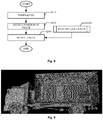
- Fig. 6 shows a container truck under inspection, and is one of the three images captured in the above embodiment.
- Fig. 7 shows a process of position identification and modeling of the container as explained below.
- ⁇ represents an air value for a current linear detector array which is capturing an image (i.e., an image captured when there is only air in the relevant area), and I represents a reading of a detector in the current linear detector array.
- the transformed image gray value Ux is insensitive to instability of dosage.
- a top edge is detected at step S120.
- the top edge of the container may be detected using a morphological method to calculate a morphological gradient, and using the Hough transform. If no top edge is detected, an error is returned at step S150.
- step S140 the head part of the truck is removed, leaving only the container part.
- the upper edge of the chassis in the truck is detected in the same way as detection of the top edge of the container.
- the exact position and size of the container can be obtained after detection of the container top edge and the chassis upper edge.
- the container is modeled.
- the type of the container is determined, and accordingly a suitable 3D model is selected from a template library, which will be imported in 3D reconstruction.
- the truck part For a container truck under safety inspection, the truck part is generally of less importance. 3D information of the truck part may be restored quickly and effectively by using a modeling method. The position and size of the truck part are first identified as features, and then a best 3D template for the truck part is found in a template library.
- Fig. 8 shows a process of identifying and modeling the truck part.
- the position of the truck part in an image is identified mainly based on edge information. Given that the container has been identified, the type of the truck and the position of the truck head are identified.
- detection of the truck position may be performed in three steps: pre-processing of strip removal to obtain an image with a gentle change in background; calculating gradients and quantizing a map of the gradients to remove influence from small gradient fluctuations; and locating an maximal continuous area (i.e., the truck position) of horizontal and vertical projections in the binarized gradient map.
- the pre-processing of strip removal includes removing strips in each of horizontal and vertical directions.
- a sequence of projections of the image in the vertical direction is first acquired.
- Each projection is subjected to median filtering, and the image line corresponding to the projection is determined as a stripe if there is a large difference before and after the filtering. Values in the image line are replaced with those of the closest, non-stripe image line.
- the gradients are obtained by quantizing the image and then calculating the gradients.
- the truck position is obtained by calculating projections in horizontal and vertical directions with respect to the gradient map, and detecting a maximal continuous area after subtracting the minimal value (i.e., removing any stripe which possibly remains). This detected area represents the truck position.
- the container is identified as above described.
- the position and orientation of the truck are determined by identifying the truck part.
- the 3D model of the truck from the template library can be used as the truck part during 3D reconstruction.
- stereoscopic reconstruction from transmission images is for the purpose of assisting in inspection, and accurate measurement is not required. Accordingly, the present disclosure focuses on rendering a stereoscopic visualization of transmission images by using depth information contained in the transmission images.
- the purpose is to distinguishably display the images of objects overlapped with each other.
- the stereoscopic visualization may be presented in two approaches. The first approach is to use a 3D presentation tool, such as OpenGL, to develop 3D presentation software which provides a 3D effect by rotation at different angles.
- the second approach is using a hardware presentation terminal.
- a 3D display for naked eye is used to display 3D data.
- Fig. 9 depicts a result of 3D reconstruction presented via OpenGL software kit.
- a method for assisting in inspection is provided by rendering a stereoscopic visualization of transmission images at different viewing angles based on depth information calculated from the transmission images. Further, the 3D modeling of the container is implemented with modeling techniques to improve accuracy in 3D reconstruction. Third, the 3D modeling of the truck is implemented with modeling techniques to enhance 3D presentation.
- the 3D presentation can be provided at different angles by using presentation software.
- the 3D presentation can be further enhanced in conjunction with hardware presentation terminal.
Landscapes
- Engineering & Computer Science (AREA)
- Physics & Mathematics (AREA)
- Life Sciences & Earth Sciences (AREA)
- Health & Medical Sciences (AREA)
- General Physics & Mathematics (AREA)
- Medical Informatics (AREA)
- High Energy & Nuclear Physics (AREA)
- Computer Graphics (AREA)
- Theoretical Computer Science (AREA)
- Pathology (AREA)
- Animal Behavior & Ethology (AREA)
- Veterinary Medicine (AREA)
- Nuclear Medicine, Radiotherapy & Molecular Imaging (AREA)
- Optics & Photonics (AREA)
- Public Health (AREA)
- Radiology & Medical Imaging (AREA)
- Biomedical Technology (AREA)
- Heart & Thoracic Surgery (AREA)
- Molecular Biology (AREA)
- Surgery (AREA)
- Biophysics (AREA)
- General Health & Medical Sciences (AREA)
- Multimedia (AREA)
- Signal Processing (AREA)
- General Life Sciences & Earth Sciences (AREA)
- Geophysics (AREA)
- Computer Hardware Design (AREA)
- General Engineering & Computer Science (AREA)
- Software Systems (AREA)
- Analysing Materials By The Use Of Radiation (AREA)
- Image Analysis (AREA)
Claims (9)
- Stereoskopisches Bildgabesystem, umfassend:eine Röntgenquelle (110), die dafür eingerichtet ist, mehrere Röntgenfächerstrahlen auszusenden;mindestens drei lineare Detektoranordnungen (120, 130, 140), wobei jede lineare Detektoranordnung in einem voreingestellten Winkel in Bezug auf die Röntgenquelle angeordnet und dafür eingerichtet ist, einen Stärkewert eines jeweiligen der Röntgenfächerstrahlen zu detektieren, die ein zu inspizierendes Objekt durchdringen, und ein jeweiliges Übertragungsbild zu bilden, wenn sich das Objekt entlang einer Richtung bewegt, die sich mit den Röntgenfächerstrahlen schneidet; undeine Rekonstruktionsvorrichtung, die dafür eingerichtet ist, jeweils zwei der gebildeten Übertragungsbilder als ein Binokularbild zu verwenden, Tiefeninformationen des Objekts auf den Übertragungsbildern zu berechnen, die berechneten Tiefeninformationen zu überlagern und zu fusionieren, um 3-dimensionale (3D-) Informationen zu erhalten, und eine 3D-Rekonstruktion auszuführen.
- Stereoskopisches Bildgabesystem nach Anspruch 1, wobei die Rekonstruktionsvorrichtung dafür eingerichtet ist, die Tiefeninformationen auf der Grundlage einer Differenz der Positionen des Objekts unterschiedlicher Tiefen in den beiden Bildern zu berechnen.
- Stereoskopisches Bildgabesystem nach Anspruch 1, wobei die Rekonstruktionsvorrichtung dafür eingerichtet ist, x- und y-Koordinaten unter Verwendung der berechneten Tiefeninformation z zu korrigieren.
- Stereoskopisches Bildgabesystem nach Anspruch 1, wobei die Rekonstruktionsvorrichtung dafür eingerichtet ist, die Tiefeninformationen zu berechnen, indem angenommen wird, dass es zwei Punkte A und B unterschiedlicher Tiefen gibt, wobei sich Punkt B rechts von Punkt A in einem rechten Detektorabtastbild befindet und Punkt B sich links von Punkt A in einem linken Detektorabtastbild befindet, und eine relative Positionsdifferenz zwischen den beiden Punkten L ist, und eine Tiefendifferenz H zwischen den beiden Punkten A und B mit L und einem Strahlwinkel α berechnet wird als

- Stereoskopisches Bildgabesystem nach Anspruch 1, wobei die Rekonstruktionsvorrichtung dafür eingerichtet ist, einen Container zu identifizieren, eine Position des Containers zu bestimmen und eine 3D-Rekonstruktion des Containers auf der Grundlage eines der Übertragungsbilder auszuführen.
- Verfahren in einem stereoskopischen Bildgabesystem, das eine Röntgenstrahlquelle und mindestens drei lineare Detektoranordnungen umfasst, wobei jede lineare Detektoranordnung in einem vorgegebenen Winkel in Bezug auf die Röntgenstrahlquelle angeordnet ist, wobei das Verfahren umfasst:Aussenden mehrerer Röntgenfächerstrahlen;Detektieren, durch jede lineare Detektoranordnung, eines Stärkewertes eines jeweiligen der Röntgenfächerstrahlen, die ein zu inspizierendes Objekt durchdringen, und Bilden eines jeweiligen Übertragungsbildes, wenn sich das Objekt entlang einer Richtung bewegt, die sich mit den Röntgenfächerstrahlen schneidet; undVerwenden von jeweils zwei der gebildeten Übertragungsbilder als ein Binokularbild, Berechnen von Tiefeninformationen des Objekts auf den Übertragungsbildern, Überlagern und Fusionieren der berechneten Tiefeninformationen, um 3-dimensionale (3D-) Informationen zu erhalten, und Ausführen einer 3D-Rekonstruktion.
- Verfahren nach Anspruch 6, wobei die Tiefeninformationen auf der Grundlage einer Differenz der Positionen des Objekts unterschiedlicher Tiefen in den beiden Bildern berechnet werden.
- Verfahren nach Anspruch 6, wobei die berechnete Tiefeninformation z zum Korrigieren von x- und y-Koordinaten verwendet wird.
- Verfahren nach Anspruch 6, wobei die Tiefeninformationen berechnet werden, indem angenommen wird, dass es zwei Punkte A und B unterschiedlicher Tiefen gibt, wobei sich Punkt B rechts von Punkt A in einem rechten Detektorabtastbild befindet und Punkt B sich links von Punkt A in einem linken Detektorabtastbild befindet, und eine relative Positionsdifferenz zwischen den beiden Punkten L ist, und eine Tiefendifferenz H zwischen den beiden Punkten A und B mit L und einem Strahlwinkel α berechnet wird als

Applications Claiming Priority (1)
| Application Number | Priority Date | Filing Date | Title |
|---|---|---|---|
| CN201310521748.1A CN104567758B (zh) | 2013-10-29 | 2013-10-29 | 立体成像系统及其方法 |
Publications (2)
| Publication Number | Publication Date |
|---|---|
| EP2869094A1 EP2869094A1 (de) | 2015-05-06 |
| EP2869094B1 true EP2869094B1 (de) | 2020-05-20 |
Family
ID=51846478
Family Applications (1)
| Application Number | Title | Priority Date | Filing Date |
|---|---|---|---|
| EP14190459.9A Active EP2869094B1 (de) | 2013-10-29 | 2014-10-27 | Stereoskopische Abbildungssysteme und Verfahren |
Country Status (4)
| Country | Link |
|---|---|
| US (1) | US9763630B2 (de) |
| EP (1) | EP2869094B1 (de) |
| CN (1) | CN104567758B (de) |
| WO (1) | WO2015062352A1 (de) |
Families Citing this family (16)
| Publication number | Priority date | Publication date | Assignee | Title |
|---|---|---|---|---|
| CN105809655B (zh) * | 2014-12-30 | 2021-06-29 | 清华大学 | 车辆检查方法和系统 |
| CN106296825B (zh) * | 2016-07-27 | 2019-02-05 | 中国科学院半导体研究所 | 一种仿生三维信息生成系统及方法 |
| CN108734183A (zh) * | 2017-04-14 | 2018-11-02 | 清华大学 | 检查方法和检查设备 |
| CN107228867A (zh) * | 2017-06-21 | 2017-10-03 | 同方威视技术股份有限公司 | 安检图像显示方法、设备和安检系统 |
| WO2020093321A1 (zh) * | 2018-11-08 | 2020-05-14 | 成都频泰鼎丰企业管理中心(有限合伙) | 三维测量设备 |
| CN111221049B (zh) * | 2020-03-18 | 2022-08-26 | 苏州瑞迈斯医疗科技有限公司 | 一种三维断层成像设备 |
| CN111399073A (zh) * | 2020-03-26 | 2020-07-10 | 浙江大华技术股份有限公司 | 一种智能安检方法、智能安检机及计算机可读存储介质 |
| CN111626930A (zh) * | 2020-04-30 | 2020-09-04 | 兰州大学 | 全方位的三维照相方法 |
| CN112784814B (zh) * | 2021-02-10 | 2024-06-07 | 中联重科股份有限公司 | 车辆倒车入库的姿态识别方法及输送车倒车入库引导系统 |
| CN113595608B (zh) * | 2021-06-23 | 2022-04-12 | 清华大学 | 基于视觉感知的毫米波/太赫兹通信方法、装置和系统 |
| CN113607760B (zh) * | 2021-08-27 | 2025-03-18 | 上海太易检测技术有限公司 | 一种双光源四视角的新型x射线异物检测系统 |
| CN113567478A (zh) * | 2021-08-27 | 2021-10-29 | 上海太易检测技术有限公司 | 一种单光源三视角的新型x射线异物检测系统 |
| CN118235216A (zh) | 2021-10-01 | 2024-06-21 | 拉皮斯坎控股公司 | 用于并发产生多个基本相似的x射线束的方法和系统 |
| CN118447067A (zh) * | 2024-05-11 | 2024-08-06 | 同方威视技术股份有限公司 | 一种图像处理方法、装置和透射扫描系统 |
| CN118397844B (zh) * | 2024-06-25 | 2024-09-06 | 大唐智创(山东)科技有限公司 | 一种融合机器学习算法的智能管控服务器及终端 |
| CN121120949B (zh) * | 2025-11-11 | 2026-03-31 | 杭州睿影科技有限公司 | 一种图像重建方法及处理设备 |
Family Cites Families (20)
| Publication number | Priority date | Publication date | Assignee | Title |
|---|---|---|---|---|
| US5493595A (en) * | 1982-02-24 | 1996-02-20 | Schoolman Scientific Corp. | Stereoscopically displayed three dimensional medical imaging |
| US7054475B2 (en) * | 2001-12-28 | 2006-05-30 | General Electric Company | Apparatus and method for volumetric reconstruction of a cyclically moving object |
| GB2390005A (en) * | 2002-06-17 | 2003-12-24 | Royal Holloway University Of L | Screening Apparatus |
| DE102004022427B4 (de) | 2004-05-06 | 2007-02-08 | Yxlon International Security Gmbh | Verfahren zur Überprüfung eines Gepäckstücks |
| JP4649219B2 (ja) * | 2005-02-01 | 2011-03-09 | キヤノン株式会社 | 立体画像生成装置 |
| CN200956018Y (zh) * | 2006-05-08 | 2007-10-03 | 清华大学 | 一种多视角航空集装箱安全检查系统 |
| DE102006055641B4 (de) * | 2006-11-22 | 2013-01-31 | Visumotion Gmbh | Anordnung und Verfahren zur Aufnahme und Wiedergabe von Bildern einer Szene und/oder eines Objektes |
| WO2008080281A1 (en) * | 2006-12-28 | 2008-07-10 | Nuctech Company Limited | Radiation imaging method and system for dual-view scanning |
| CN201043955Y (zh) * | 2006-12-28 | 2008-04-02 | 同方威视技术股份有限公司 | 双视角扫描辐射成像装置 |
| CN101347335B (zh) * | 2007-03-14 | 2010-11-03 | 张迎光 | 能产生立体视觉效果的x射线发生装置及医用x射线设备 |
| FR2919780B1 (fr) * | 2007-08-02 | 2017-09-08 | Nuctech Co Ltd | Procede et systeme d'identification de matiere a l'aide d'images binoculaires stereoscopiques et par transmission multi-energie |
| US20090232277A1 (en) * | 2008-03-14 | 2009-09-17 | General Electric Company | System and method for inspection of items of interest in objects |
| CN102099708A (zh) * | 2008-05-19 | 2011-06-15 | 显示成像技术有限公司 | 通过使用发射众多的扇形光束的x射线光源来检查行李的x射线装置 |
| IT1401367B1 (it) * | 2010-07-28 | 2013-07-18 | Sisvel Technology Srl | Metodo per combinare immagini riferentesi ad un contenuto tridimensionale. |
| CN102411157B (zh) * | 2011-08-05 | 2014-10-29 | 北京睿思厚德辐射信息科技开发有限公司 | 物体单侧扫描双侧立体成像的方法及装置 |
| CN202903699U (zh) * | 2012-07-30 | 2013-04-24 | 公安部第一研究所 | 一种通道式四视角x射线液态物品安全检查系统 |
| CN107346061B (zh) * | 2012-08-21 | 2020-04-24 | 快图有限公司 | 用于使用阵列照相机捕捉的图像中的视差检测和校正的系统和方法 |
| CN203012155U (zh) * | 2012-12-27 | 2013-06-19 | 同方威视技术股份有限公司 | 一种无机架ct装置 |
| CN203084216U (zh) * | 2012-12-27 | 2013-07-24 | 同方威视技术股份有限公司 | 固定式ct装置 |
| CN103226114B (zh) * | 2013-04-02 | 2015-09-30 | 清华大学 | 多视角立体辐射成像系统及方法 |
-
2013
- 2013-10-29 CN CN201310521748.1A patent/CN104567758B/zh active Active
-
2014
- 2014-08-26 WO PCT/CN2014/085153 patent/WO2015062352A1/zh not_active Ceased
- 2014-10-27 EP EP14190459.9A patent/EP2869094B1/de active Active
- 2014-10-27 US US14/525,078 patent/US9763630B2/en active Active
Non-Patent Citations (1)
| Title |
|---|
| None * |
Also Published As
| Publication number | Publication date |
|---|---|
| US20150117602A1 (en) | 2015-04-30 |
| EP2869094A1 (de) | 2015-05-06 |
| CN104567758B (zh) | 2017-11-17 |
| WO2015062352A1 (zh) | 2015-05-07 |
| CN104567758A (zh) | 2015-04-29 |
| US9763630B2 (en) | 2017-09-19 |
Similar Documents
| Publication | Publication Date | Title |
|---|---|---|
| EP2869094B1 (de) | Stereoskopische Abbildungssysteme und Verfahren | |
| US8687861B2 (en) | Image reconstructing method using X-ray volume photography | |
| US6381302B1 (en) | Computer assisted 2D adjustment of stereo X-ray images | |
| US8670522B2 (en) | Stereo X-ray inspection apparatus and method for forming three-dimensional image through volume reconstruction of image acquired from the same | |
| EP3049793B1 (de) | Strukturelle überwachung von heisspunkten und kritischen stellen | |
| US20090232355A1 (en) | Registration of 3d point cloud data using eigenanalysis | |
| CN103226114B (zh) | 多视角立体辐射成像系统及方法 | |
| US20060078085A1 (en) | Stereoscopic x-ray imaging apparatus for obtaining three dimensional coordinates | |
| CN102589530B (zh) | 基于二维相机和三维相机融合的非合作目标位姿测量方法 | |
| CN101358936A (zh) | 一种利用双视角多能量透射图像进行材料识别的方法及系统 | |
| JP2012517651A (ja) | 2d電子光学的画像データに対する3d点群データの登録 | |
| KR20150079560A (ko) | 콘빔 컴퓨터 단층 촬영 장치의 기하 특성화 및 교정 | |
| JP2008309533A (ja) | 車両形状計測方法と装置 | |
| WO2014101386A1 (zh) | 三维数据处理和识别方法 | |
| Shang et al. | Single-pass inline pipeline 3D reconstruction using depth camera array | |
| KR102265248B1 (ko) | 3-d 이미징에 의해 장면의 오브젝트들의 구별 및 식별을 위한 방법 | |
| CN101900694A (zh) | 基于直线轨迹扫描的双能欠采样物质识别系统和方法 | |
| HK1245975A1 (en) | Method for discrimination and identification of objects of a scene by 3-d imaging | |
| WO2016101829A1 (zh) | 一种安检ct三维图像的操作方法和装置 | |
| CN114004765A (zh) | 一种安检设备中dr透视图像的畸变校正方法及装置 | |
| JP4082718B2 (ja) | 画像認識方法および画像表示方法および画像認識装置 | |
| CN113643360B (zh) | 目标物体定位方法、装置、设备、介质和程序产品 | |
| Zhu et al. | 3D Measurements in cargo inspection with a gamma-ray linear pushbroom stereo system | |
| CN201043955Y (zh) | 双视角扫描辐射成像装置 | |
| Villa et al. | Robust Landmark and Hazard Detection on Small Body Surfaces Using Shadow Imagery |
Legal Events
| Date | Code | Title | Description |
|---|---|---|---|
| PUAI | Public reference made under article 153(3) epc to a published international application that has entered the european phase |
Free format text: ORIGINAL CODE: 0009012 |
|
| 17P | Request for examination filed |
Effective date: 20141027 |
|
| AK | Designated contracting states |
Kind code of ref document: A1 Designated state(s): AL AT BE BG CH CY CZ DE DK EE ES FI FR GB GR HR HU IE IS IT LI LT LU LV MC MK MT NL NO PL PT RO RS SE SI SK SM TR |
|
| AX | Request for extension of the european patent |
Extension state: BA ME |
|
| R17P | Request for examination filed (corrected) |
Effective date: 20151104 |
|
| RBV | Designated contracting states (corrected) |
Designated state(s): AL AT BE BG CH CY CZ DE DK EE ES FI FR GB GR HR HU IE IS IT LI LT LU LV MC MK MT NL NO PL PT RO RS SE SI SK SM TR |
|
| STAA | Information on the status of an ep patent application or granted ep patent |
Free format text: STATUS: EXAMINATION IS IN PROGRESS |
|
| 17Q | First examination report despatched |
Effective date: 20181106 |
|
| GRAP | Despatch of communication of intention to grant a patent |
Free format text: ORIGINAL CODE: EPIDOSNIGR1 |
|
| STAA | Information on the status of an ep patent application or granted ep patent |
Free format text: STATUS: GRANT OF PATENT IS INTENDED |
|
| INTG | Intention to grant announced |
Effective date: 20191213 |
|
| RIN1 | Information on inventor provided before grant (corrected) |
Inventor name: CUI, JIN Inventor name: TU, ZHUOWEN Inventor name: ZHAO, ZIRAN Inventor name: ZHANG, DUOKUN Inventor name: PENG, ZHI Inventor name: CHEN, ZHIQIANG Inventor name: LIN, DONG Inventor name: LI, LIANG |
|
| GRAS | Grant fee paid |
Free format text: ORIGINAL CODE: EPIDOSNIGR3 |
|
| GRAA | (expected) grant |
Free format text: ORIGINAL CODE: 0009210 |
|
| STAA | Information on the status of an ep patent application or granted ep patent |
Free format text: STATUS: THE PATENT HAS BEEN GRANTED |
|
| AK | Designated contracting states |
Kind code of ref document: B1 Designated state(s): AL AT BE BG CH CY CZ DE DK EE ES FI FR GB GR HR HU IE IS IT LI LT LU LV MC MK MT NL NO PL PT RO RS SE SI SK SM TR |
|
| REG | Reference to a national code |
Ref country code: GB Ref legal event code: FG4D |
|
| REG | Reference to a national code |
Ref country code: CH Ref legal event code: EP |
|
| REG | Reference to a national code |
Ref country code: DE Ref legal event code: R096 Ref document number: 602014065657 Country of ref document: DE |
|
| REG | Reference to a national code |
Ref country code: AT Ref legal event code: REF Ref document number: 1272959 Country of ref document: AT Kind code of ref document: T Effective date: 20200615 |
|
| REG | Reference to a national code |
Ref country code: LT Ref legal event code: MG4D |
|
| REG | Reference to a national code |
Ref country code: NL Ref legal event code: MP Effective date: 20200520 |
|
| PG25 | Lapsed in a contracting state [announced via postgrant information from national office to epo] |
Ref country code: PT Free format text: LAPSE BECAUSE OF FAILURE TO SUBMIT A TRANSLATION OF THE DESCRIPTION OR TO PAY THE FEE WITHIN THE PRESCRIBED TIME-LIMIT Effective date: 20200921 Ref country code: FI Free format text: LAPSE BECAUSE OF FAILURE TO SUBMIT A TRANSLATION OF THE DESCRIPTION OR TO PAY THE FEE WITHIN THE PRESCRIBED TIME-LIMIT Effective date: 20200520 Ref country code: LT Free format text: LAPSE BECAUSE OF FAILURE TO SUBMIT A TRANSLATION OF THE DESCRIPTION OR TO PAY THE FEE WITHIN THE PRESCRIBED TIME-LIMIT Effective date: 20200520 Ref country code: GR Free format text: LAPSE BECAUSE OF FAILURE TO SUBMIT A TRANSLATION OF THE DESCRIPTION OR TO PAY THE FEE WITHIN THE PRESCRIBED TIME-LIMIT Effective date: 20200821 Ref country code: SE Free format text: LAPSE BECAUSE OF FAILURE TO SUBMIT A TRANSLATION OF THE DESCRIPTION OR TO PAY THE FEE WITHIN THE PRESCRIBED TIME-LIMIT Effective date: 20200520 Ref country code: NO Free format text: LAPSE BECAUSE OF FAILURE TO SUBMIT A TRANSLATION OF THE DESCRIPTION OR TO PAY THE FEE WITHIN THE PRESCRIBED TIME-LIMIT Effective date: 20200820 Ref country code: IS Free format text: LAPSE BECAUSE OF FAILURE TO SUBMIT A TRANSLATION OF THE DESCRIPTION OR TO PAY THE FEE WITHIN THE PRESCRIBED TIME-LIMIT Effective date: 20200920 |
|
| PG25 | Lapsed in a contracting state [announced via postgrant information from national office to epo] |
Ref country code: HR Free format text: LAPSE BECAUSE OF FAILURE TO SUBMIT A TRANSLATION OF THE DESCRIPTION OR TO PAY THE FEE WITHIN THE PRESCRIBED TIME-LIMIT Effective date: 20200520 Ref country code: LV Free format text: LAPSE BECAUSE OF FAILURE TO SUBMIT A TRANSLATION OF THE DESCRIPTION OR TO PAY THE FEE WITHIN THE PRESCRIBED TIME-LIMIT Effective date: 20200520 Ref country code: BG Free format text: LAPSE BECAUSE OF FAILURE TO SUBMIT A TRANSLATION OF THE DESCRIPTION OR TO PAY THE FEE WITHIN THE PRESCRIBED TIME-LIMIT Effective date: 20200820 Ref country code: RS Free format text: LAPSE BECAUSE OF FAILURE TO SUBMIT A TRANSLATION OF THE DESCRIPTION OR TO PAY THE FEE WITHIN THE PRESCRIBED TIME-LIMIT Effective date: 20200520 |
|
| REG | Reference to a national code |
Ref country code: AT Ref legal event code: MK05 Ref document number: 1272959 Country of ref document: AT Kind code of ref document: T Effective date: 20200520 |
|
| PG25 | Lapsed in a contracting state [announced via postgrant information from national office to epo] |
Ref country code: AL Free format text: LAPSE BECAUSE OF FAILURE TO SUBMIT A TRANSLATION OF THE DESCRIPTION OR TO PAY THE FEE WITHIN THE PRESCRIBED TIME-LIMIT Effective date: 20200520 Ref country code: NL Free format text: LAPSE BECAUSE OF FAILURE TO SUBMIT A TRANSLATION OF THE DESCRIPTION OR TO PAY THE FEE WITHIN THE PRESCRIBED TIME-LIMIT Effective date: 20200520 |
|
| PG25 | Lapsed in a contracting state [announced via postgrant information from national office to epo] |
Ref country code: CZ Free format text: LAPSE BECAUSE OF FAILURE TO SUBMIT A TRANSLATION OF THE DESCRIPTION OR TO PAY THE FEE WITHIN THE PRESCRIBED TIME-LIMIT Effective date: 20200520 Ref country code: RO Free format text: LAPSE BECAUSE OF FAILURE TO SUBMIT A TRANSLATION OF THE DESCRIPTION OR TO PAY THE FEE WITHIN THE PRESCRIBED TIME-LIMIT Effective date: 20200520 Ref country code: ES Free format text: LAPSE BECAUSE OF FAILURE TO SUBMIT A TRANSLATION OF THE DESCRIPTION OR TO PAY THE FEE WITHIN THE PRESCRIBED TIME-LIMIT Effective date: 20200520 Ref country code: EE Free format text: LAPSE BECAUSE OF FAILURE TO SUBMIT A TRANSLATION OF THE DESCRIPTION OR TO PAY THE FEE WITHIN THE PRESCRIBED TIME-LIMIT Effective date: 20200520 Ref country code: SM Free format text: LAPSE BECAUSE OF FAILURE TO SUBMIT A TRANSLATION OF THE DESCRIPTION OR TO PAY THE FEE WITHIN THE PRESCRIBED TIME-LIMIT Effective date: 20200520 Ref country code: DK Free format text: LAPSE BECAUSE OF FAILURE TO SUBMIT A TRANSLATION OF THE DESCRIPTION OR TO PAY THE FEE WITHIN THE PRESCRIBED TIME-LIMIT Effective date: 20200520 Ref country code: AT Free format text: LAPSE BECAUSE OF FAILURE TO SUBMIT A TRANSLATION OF THE DESCRIPTION OR TO PAY THE FEE WITHIN THE PRESCRIBED TIME-LIMIT Effective date: 20200520 Ref country code: IT Free format text: LAPSE BECAUSE OF FAILURE TO SUBMIT A TRANSLATION OF THE DESCRIPTION OR TO PAY THE FEE WITHIN THE PRESCRIBED TIME-LIMIT Effective date: 20200520 |
|
| REG | Reference to a national code |
Ref country code: DE Ref legal event code: R097 Ref document number: 602014065657 Country of ref document: DE |
|
| PG25 | Lapsed in a contracting state [announced via postgrant information from national office to epo] |
Ref country code: PL Free format text: LAPSE BECAUSE OF FAILURE TO SUBMIT A TRANSLATION OF THE DESCRIPTION OR TO PAY THE FEE WITHIN THE PRESCRIBED TIME-LIMIT Effective date: 20200520 Ref country code: SK Free format text: LAPSE BECAUSE OF FAILURE TO SUBMIT A TRANSLATION OF THE DESCRIPTION OR TO PAY THE FEE WITHIN THE PRESCRIBED TIME-LIMIT Effective date: 20200520 |
|
| PLBE | No opposition filed within time limit |
Free format text: ORIGINAL CODE: 0009261 |
|
| STAA | Information on the status of an ep patent application or granted ep patent |
Free format text: STATUS: NO OPPOSITION FILED WITHIN TIME LIMIT |
|
| 26N | No opposition filed |
Effective date: 20210223 |
|
| REG | Reference to a national code |
Ref country code: DE Ref legal event code: R119 Ref document number: 602014065657 Country of ref document: DE |
|
| PG25 | Lapsed in a contracting state [announced via postgrant information from national office to epo] |
Ref country code: SI Free format text: LAPSE BECAUSE OF FAILURE TO SUBMIT A TRANSLATION OF THE DESCRIPTION OR TO PAY THE FEE WITHIN THE PRESCRIBED TIME-LIMIT Effective date: 20200520 |
|
| REG | Reference to a national code |
Ref country code: CH Ref legal event code: PL |
|
| GBPC | Gb: european patent ceased through non-payment of renewal fee |
Effective date: 20201027 |
|
| PG25 | Lapsed in a contracting state [announced via postgrant information from national office to epo] |
Ref country code: MC Free format text: LAPSE BECAUSE OF FAILURE TO SUBMIT A TRANSLATION OF THE DESCRIPTION OR TO PAY THE FEE WITHIN THE PRESCRIBED TIME-LIMIT Effective date: 20200520 Ref country code: LU Free format text: LAPSE BECAUSE OF NON-PAYMENT OF DUE FEES Effective date: 20201027 |
|
| REG | Reference to a national code |
Ref country code: BE Ref legal event code: MM Effective date: 20201031 |
|
| PG25 | Lapsed in a contracting state [announced via postgrant information from national office to epo] |
Ref country code: FR Free format text: LAPSE BECAUSE OF NON-PAYMENT OF DUE FEES Effective date: 20201031 Ref country code: DE Free format text: LAPSE BECAUSE OF NON-PAYMENT OF DUE FEES Effective date: 20210501 |
|
| PG25 | Lapsed in a contracting state [announced via postgrant information from national office to epo] |
Ref country code: BE Free format text: LAPSE BECAUSE OF NON-PAYMENT OF DUE FEES Effective date: 20201031 Ref country code: CH Free format text: LAPSE BECAUSE OF NON-PAYMENT OF DUE FEES Effective date: 20201031 Ref country code: GB Free format text: LAPSE BECAUSE OF NON-PAYMENT OF DUE FEES Effective date: 20201027 Ref country code: LI Free format text: LAPSE BECAUSE OF NON-PAYMENT OF DUE FEES Effective date: 20201031 |
|
| PG25 | Lapsed in a contracting state [announced via postgrant information from national office to epo] |
Ref country code: IE Free format text: LAPSE BECAUSE OF NON-PAYMENT OF DUE FEES Effective date: 20201027 |
|
| PG25 | Lapsed in a contracting state [announced via postgrant information from national office to epo] |
Ref country code: TR Free format text: LAPSE BECAUSE OF FAILURE TO SUBMIT A TRANSLATION OF THE DESCRIPTION OR TO PAY THE FEE WITHIN THE PRESCRIBED TIME-LIMIT Effective date: 20200520 Ref country code: MT Free format text: LAPSE BECAUSE OF FAILURE TO SUBMIT A TRANSLATION OF THE DESCRIPTION OR TO PAY THE FEE WITHIN THE PRESCRIBED TIME-LIMIT Effective date: 20200520 Ref country code: CY Free format text: LAPSE BECAUSE OF FAILURE TO SUBMIT A TRANSLATION OF THE DESCRIPTION OR TO PAY THE FEE WITHIN THE PRESCRIBED TIME-LIMIT Effective date: 20200520 |
|
| PG25 | Lapsed in a contracting state [announced via postgrant information from national office to epo] |
Ref country code: MK Free format text: LAPSE BECAUSE OF FAILURE TO SUBMIT A TRANSLATION OF THE DESCRIPTION OR TO PAY THE FEE WITHIN THE PRESCRIBED TIME-LIMIT Effective date: 20200520 |