EP2869168A1 - Système de détection tactile et appareil d'affichage - Google Patents
Système de détection tactile et appareil d'affichage Download PDFInfo
- Publication number
- EP2869168A1 EP2869168A1 EP20140181887 EP14181887A EP2869168A1 EP 2869168 A1 EP2869168 A1 EP 2869168A1 EP 20140181887 EP20140181887 EP 20140181887 EP 14181887 A EP14181887 A EP 14181887A EP 2869168 A1 EP2869168 A1 EP 2869168A1
- Authority
- EP
- European Patent Office
- Prior art keywords
- touch
- sensing
- bridge
- controller
- sensing data
- Prior art date
- Legal status (The legal status is an assumption and is not a legal conclusion. Google has not performed a legal analysis and makes no representation as to the accuracy of the status listed.)
- Granted
Links
Images






Classifications
-
- G—PHYSICS
- G06—COMPUTING OR CALCULATING; COUNTING
- G06F—ELECTRIC DIGITAL DATA PROCESSING
- G06F3/00—Input arrangements for transferring data to be processed into a form capable of being handled by the computer; Output arrangements for transferring data from processing unit to output unit, e.g. interface arrangements
- G06F3/01—Input arrangements or combined input and output arrangements for interaction between user and computer
- G06F3/03—Arrangements for converting the position or the displacement of a member into a coded form
- G06F3/041—Digitisers, e.g. for touch screens or touch pads, characterised by the transducing means
- G06F3/0416—Control or interface arrangements specially adapted for digitisers
- G06F3/04166—Details of scanning methods, e.g. sampling time, grouping of sub areas or time sharing with display driving
-
- G—PHYSICS
- G06—COMPUTING OR CALCULATING; COUNTING
- G06F—ELECTRIC DIGITAL DATA PROCESSING
- G06F3/00—Input arrangements for transferring data to be processed into a form capable of being handled by the computer; Output arrangements for transferring data from processing unit to output unit, e.g. interface arrangements
- G06F3/01—Input arrangements or combined input and output arrangements for interaction between user and computer
- G06F3/03—Arrangements for converting the position or the displacement of a member into a coded form
- G06F3/041—Digitisers, e.g. for touch screens or touch pads, characterised by the transducing means
- G06F3/0416—Control or interface arrangements specially adapted for digitisers
-
- G—PHYSICS
- G06—COMPUTING OR CALCULATING; COUNTING
- G06F—ELECTRIC DIGITAL DATA PROCESSING
- G06F3/00—Input arrangements for transferring data to be processed into a form capable of being handled by the computer; Output arrangements for transferring data from processing unit to output unit, e.g. interface arrangements
- G06F3/01—Input arrangements or combined input and output arrangements for interaction between user and computer
- G06F3/03—Arrangements for converting the position or the displacement of a member into a coded form
- G06F3/041—Digitisers, e.g. for touch screens or touch pads, characterised by the transducing means
- G06F3/044—Digitisers, e.g. for touch screens or touch pads, characterised by the transducing means by capacitive means
-
- G—PHYSICS
- G06—COMPUTING OR CALCULATING; COUNTING
- G06F—ELECTRIC DIGITAL DATA PROCESSING
- G06F3/00—Input arrangements for transferring data to be processed into a form capable of being handled by the computer; Output arrangements for transferring data from processing unit to output unit, e.g. interface arrangements
- G06F3/01—Input arrangements or combined input and output arrangements for interaction between user and computer
- G06F3/03—Arrangements for converting the position or the displacement of a member into a coded form
- G06F3/041—Digitisers, e.g. for touch screens or touch pads, characterised by the transducing means
- G06F3/044—Digitisers, e.g. for touch screens or touch pads, characterised by the transducing means by capacitive means
- G06F3/0446—Digitisers, e.g. for touch screens or touch pads, characterised by the transducing means by capacitive means using a grid-like structure of electrodes in at least two directions, e.g. using row and column electrodes
-
- G—PHYSICS
- G06—COMPUTING OR CALCULATING; COUNTING
- G06F—ELECTRIC DIGITAL DATA PROCESSING
- G06F2203/00—Indexing scheme relating to G06F3/00 - G06F3/048
- G06F2203/041—Indexing scheme relating to G06F3/041 - G06F3/045
- G06F2203/04111—Cross over in capacitive digitiser, i.e. details of structures for connecting electrodes of the sensing pattern where the connections cross each other, e.g. bridge structures comprising an insulating layer, or vias through substrate
Definitions
- the present invention relates to a touch sensing system and a display apparatus.
- LCD Liquid Crystal Display
- PDP Plasma Display Panel
- OLED Organic Light Emitting Diode
- the display apparatus provides an input method based on a touch that enables a user to input information or an instruction easily, directly and conveniently, getting away from the usual input methods, such as pushing a button, a keyboard, a mouse, etc.
- a touch panel should be included in the display apparatus.
- An aspect of the present invention is to provide a touch sensing system and a display apparatus decreasing a sensing time and enabling an effective touch sensing, although a number of sensing electrodes increases according to an increase of an area of a touch panel.
- a touch sensing system including: a touch panel including driving electrodes and sensing electrodes defining sensor nodes; two or more touch integrated circuits that sense sensing information of each of the corresponding sensor nodes from connected sensing electrodes among the sensing electrodes by sequentially driving the driving electrodes, and transmit sensing data including the sensed sensing information of each of the corresponding sensor nodes; a bridge that aligns the sensing data transmitted from each of the two or more touch integrated circuits based on a sensor node position, and transmits the sensing data; and a controller that detects a touch coordinate based on a whole or a portion of the sensing data transmitted from the bridge.
- a display apparatus including: a touch panel including driving electrodes and sensing electrodes defining sensor nodes; and a printed circuit board attached to one side of the touch panel, and including two or more touch integrated circuits sensing the sensor nodes and transmitting sensing data, a bridge aligning the sensing data transmitted from each of the two or more touch integrated circuits and transmitting the sensing data, and a controller detecting a touch coordinate based on a whole or a portion of the sensing data transmitted from the bridge.
- a touch sensing system including: a touch panel including driving electrodes and sensing electrodes defining sensor nodes; two or more touch integrated circuits that sense sensing information of each of the corresponding sensor nodes from connected sensing electrodes among the sensing electrodes by sequentially driving the driving electrodes, transmit sensing data including the sensed sensing information of each of the corresponding sensor nodes, and transmit touch generation or non-generation information determined in each of the sensor nodes defined by the connected sensing electrodes or a touch integrated circuit tag corresponding to the touch generation or non-generation information; and a controller that detects a touch coordinate based on only a portion of the sensing data among a whole of the sensing data transmitted from each of the two or more touch integrated circuits and based on the touch generation or non-generation information or the touch integrated circuit tags respectively corresponding to the two or more touch integrated circuits.
- the present invention there is an effect of providing the touch sensing system and the display apparatus capable which decrease a sensing time and enable an effective touch sensing, although a number of the sensing electrodes increases according to an increase of an area of a touch panel.
- the bridge As an additional configuration receiving divided and sensed sensing data from the two or more touch integrated circuits (ICs) in parallel, assigning and combining the received sensing data, among the two or more touch ICs and the controller performing the touch algorithm is further disclosed. Therefore, delays of the sensing data transmission and the touch algorithm performance, rather may be generated by the Rx division sensing method suggested for increasing the effectiveness of the touch sensing when the number of the sensing electrodes increases according to the increase of the area of the touch panel, decrease. Thus, there is an effect of enabling high speed sensing data transmission and touch algorithm performance.
- an input/output (I/O) collision may be generated according to memory uses of each of the controller and the bridge.
- the number of the sensing electrodes increases due to the increase of the area of the touch panel, a sensing data amount stored in the memory and read from the memory increases.
- a touch coordinate is detected with respect to only a partial area where it is determined that a touch is generated, not a whole area on a touch panel.
- only a necessary sensing data is read partially, therefore there is an effect of decreasing the amount of the sensing data which should be read by the controller and enabling the controller to process the touch algorithm faster.
- first, second, A, B, (a), (b) or the like may be used herein when describing components of the present invention.
- Each of these terminologies is not used to define an essence, order or sequence of a corresponding component but used merely to distinguish the corresponding component from other component(s).
- another structural element may "be connected to", “be coupled to”, or “be in contact with” the structural elements as well as that the certain structural element is directly connected to or is in direct contact with another structural element.
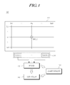
- FIG. 1 is a view schematically illustrating a touch sensing system 100 according to an exemplary embodiment. All the components of the touch sensing system, according to all the embodiments of the present invention, are operatively coupled and configured.
- the touch sensing system 100 includes a touch panel 110 including N number of driving electrodes Tx1 to TxN and M number of sensing electrodes Rx1 to RxM, two or more touch Integrated Circuits (ICs) 120 for a reception (Rx) division sensing, a bridge 130 aligning and combining sensing data generated from each of the two or more touch ICs 120 through a sensing a sensor node, a controller 140 detecting a touch coordinate based on the whole or a portion of the sensing data aligned and combined in the bridge 130, etc.
- ICs Integrated Circuits
- the N number of driving electrodes Tx1 to TxN and the M number of sensing electrodes Rx1 to RxM are formed, and thus (N*M) number of sensor nodes SN(1,1) to SN(1,M), SN(2,1) to SN(2,M), ..., SN(N,M) are defined.
- the SN(i,j) is a sensor node defined by an ith driving electrode Txi and a jth sensing electrode Rxj (here, 1 ⁇ i ⁇ N, 1 ⁇ j ⁇ M, N is a number of the driving electrode, and M is a number of the sensing electrode).
- the two or more touch ICs 120 performs the Rx division sensing, and thus the two or more touch ICs 120 divide the whole sensor node by a certain number to sense the whole sensor node.
- each of the two or more touch ICs 120 senses sensing information (e.g., a capacitance) of each of the sensor nodes from connected sensing electrodes among the M number of sensing electrodes (Rx1 to RxM) by sequentially driving the N number of driving electrodes (Tx1 to TxN).
- sensing information e.g., a capacitance
- each of the two or more touch ICs 120 may transmit sensing data including the sensing information sensed in each of the sensor nodes managed by the touch IC 120.
- Each of the two or more touch ICs 120 may determine a touch generation or non-generation in an area formed by the sensor nodes defined by sensing electrodes connected to each of the two or more touch ICs 120 among the whole area of the touch panel 110, based on a charge amount change ( ⁇ Q) or a voltage change ( ⁇ V) informing the charge amount change ( ⁇ Q) in each of the sensor nodes defined by the sensing electrodes connected to each of the two or more touch ICs 120.
- ⁇ Q charge amount change
- ⁇ V voltage change
- each of the two or more touch ICs 120 may determine that a touch is generated.
- Each of two or more touch ICs 120 may transmit touch generation or non-generation information in the area formed by the sensor nodes managed by the touch IC 120 along with the sensing data including the sensing information of each of the sensor nodes managed by the touch IC 120.
- the bridge 130 aligns and combines the sensing data transmitted from each of the two or more touch ICs 120, based on a sensor node position.
- each of the N number of driving electrodes Tx1 to TxN and each of the M number of sensing electrodes Rx1 to RxM correspond, and thus each of the sensor nodes is defined.
- the bridge 130 may collect the touch generation or non-generation information transmitted from each of the two or more touch ICs 120 and provide a touch IC tag instructing a touch generation or instructing a touch non-generation to each of the two or more touch ICs 120, so that the controller 140 may check a position where the touch is generated on the touch panel 110.
- the whole or the portion of the sensing data generated by aligning and combining the sensing data from each of the two or more touch ICs 120, and the touch IC tag provided by collecting the touch generation or non-generation information of each of the two or more touch ICs 120 may be transferred from the bridge 130 to the controller 140 in a directly transmitted type (i.e., a direct delivery type).
- the whole or the portion of the sensing data and the touch IC tag transmitted from the brige 130 may be stored in a shared memory 150 and may be transferred to the controller 140 in a type (store and read type) wherein the controller 140 reads the whole or the portion of the sensing data and the touch IC tag from the shared memory 150.
- the controller 140 performs a touch algorithm based on the whole or the portion of the sensing data transmitted from the bridge 130 to detect the touch coordinate.
- the controller 140 may directly receive the whole or the portion of the sensing data transferred from the bridge 130 to detect the touch coordinate based on the whole or the portion of the sensing data.
- the controller 140 may read the whole or the portion of the sensing data transmitted from the bridge 130 and stored in the shared memory 150 to detect the touch coordinate based on the whole or the portion of the sensing data.
- performing the touch algorithm by the controller 140 by using the whole of the sensing data transmitted from the bridge 130 means detecting the touch coordinate based on the whole area of the touch panel 110
- performing the touch algorithm by the controller 140 by using the portion of the sensing data transmitted from the bridge 130 means detecting the touch coordinate based on the portion of the area where it is determined that the touch is generated among the whole of the area of the touch panel 110.
- each of the two or more touch ICs 120 may transmit the sensing data generated based on the sensed sensing information to the bridge 130 in a serial communication method.
- the sensing data transmission from each of the two or more touch ICs 120 is performed unrelated to a sensing data transmission time point of another touch IC.
- the bridge 130 may simultaneously receive the sensing data transmitted from each of two or more touch ICs 120, in parallel.
- each of the two or more touch ICs 120 transmits the corresponding sensing data to the bridge 130 in the serial communication method, because each of the two or more touch ICs 120 transmits the corresponding sensing data to the bridge 130 unrelated to the sensing data transmission time point of another touch IC 120, the two or more touch ICs 120 simultaneously transmit the sensing data in parallel, and the bridge 130 simultaneously receives the sensing data transmitted from each of the two or more touch ICs 120, in parallel.
- the bridge 130 simultaneously receives the sensing data transmitted from each of the two or more touch ICs 120, in parallel, and aligns and combines the sensing data. In addtion, the bridge 130 transmits the aligned and combined sensing data to the controller 140 or stores the aligned and combined sensing data to the shared memory 150 according to a parallel communication method so that the controller 140 may use the sensing data in the touch algorithm.
- the bridge 130 may transmit or store the touch IC tag to the controller 140 or the shared memory 150.
- the controller 140 reads the whole or the portion of the sensing data transmitted from the bridge 130 and stored in the shared memory 150, detects the touch coordinate based on the read sensing data.
- the controller 140 When the controller 140 reads the portion among the whole of the sensing data tansmitted from the bridge 130 and stored in the shared memory 150, the controller 140 reads only the portion of the sensing data, transmitted from the touch IC 120, connected to the sensing electrodes in the partial area corresponding to the point where the touch is generated among the whole area of the touch panel 110, to the bridge 130 and stored in the shared memory 150, among the whole of the sensing data stored in the shared memory 150, based on the touch IC tag stored in the shared memory 150 in correspondence to each of the two or more touch ICs 120, and performs the touch algorithm to detect the touch coordinate (refer to FIG. 4A ).
- a touch coordinate detection error may be generated.
- the controller 140 may read the portion of the sensing data, transmitted from the two touch ICs 120, connected to the sensing electrodes in each of two areas of both sides of the point where the touch is generated among the whole area of the touch panel 110 or the adjacent area adjacent to the point where the touch is generated among the whole area of the touch panel 110, to the bridge 130 and stored in the shared memory 150, among the whole of the sensing data stored in the shared memory 150, based on the touch IC tag stored in the shared memory 150 in correspondence to the two or more touch ICs 120, respectively (refer to FIG. 4B ).
- the data amount read from the shared memory 150 by the controller 140 may decrease, and a process speed of the touch algorithm of the controller 140 may be faster.
- the controller 140 detects the touch coordinate based on the whole or the portion of the sensing data transmitted from the bridge 130.
- the controller 140 detects the touch coordinate based on only the portion of the sensing data among the whole of the sensing data transmitted from the bridge 130
- the controller 140 performs the touch algorithm based on only the sensing data transmitted to the bridge 130 from the touch IC 120 corresponding to the touch IC tag instructing the touch generation, among the whole of the sensing data transmitted from the bridge 130, based on the touch IC tag transmitted in correspondence to two or more touch ICs 120.
- a sensing data amount used for the touch algorithm performance by the controller 140 decreases, and thus a process speed of the touch algorithm of the controller 140 may be faster.
- the sensing data is not directly transferred to the controller 140 from each of the two or more touch ICs 120, but rather, the bridge 130 relays the sensing data between the two or more touch ICs 120 and the controller 140 by aligning and combining the sensing data.
- the sensing data from each of the two or more touch ICs 120 may not be sequentially transmitted to the controller 140, and the two or more touch ICs 120 may simultaneously transmit the sensing data to the controller 140 in parallel.
- the time point when the sensing data is transmitted from all of the two or more touch ICs 120 is considerably faster, and the controller 140 capable of performing the touch algorithm after all of the two or more touch ICs 120 transmit the sensing data may perform the touch algorithm at a much faster time point.
- Such a merit may be further obvious in a case wherein a number of the touch ICs increases because a size of the touch panel 110 increases and so on.
- each of the two or more touch ICs 120 determines whether the touch is generated or not on the areas of the touch panel 110 managed by the respective touch ICs 120, and informs the determination result (i.e., the touch generation or non-generation determination information). Therefore, the controller 140 detects the touch coordinate with respect to only the partial area rather than the whole area of the touch panel 110, thus the sensing data amount which should be read may decrease and the process speed of the touch algorithm may be faster.
- the touch sensing system 100 according to an exemplary embodiment desribed above is described in more detail with reference to FIGs. 2 to 6 .
- FIGs. 2A and 2B are views illustrating the touch panel 110 in the touch sensing system 100 according to an exemplary embodiment.
- the N number of driving electrodes Tx1 to TxN and the M number of sensing electrodes Rx1 to RxM are formed in the touch panel 110 of the touch sensing system 100 according to an exemplary embodiment.
- driving pulses are sequentially provided to the N number of driving electrodes Tx1 to TxN by the two or more touch ICs 120.
- the sensing information of each of the sensor nodes is sensed by the two or more touch ICs 120.
- the N number of driving electrodes Tx1 to TxN and the M number of sensing electrodes Rx1 to RxM correspond each other, and thus the N*M number of sensor nodes SN(i,j) (here, 1 ⁇ i ⁇ N, 1 ⁇ j ⁇ M, N is the number of the driving electrode, and M is a number of the sensing electrode) are defined.
- a capacitance is formed in each of the sensor nodes by the driving electrode and the sensing electrode. The capacitance formed in each of the sensor nodes or the capacitance change is measured as the sensing information according to the touch point on the touch panel 110, and thus the touch coordinate and so on are detected.
- the N number of driving electrodes Tx1 to TxN and the M number of sensing electrodes Rx1 to RxM may be formed on different layers, and may be formed on the same layer. That is, the touch panel 110 may have a double layer structure (i.e., two layers), or alternatively, the touch panel 110 may have a single layer structure (i.e., one layer).
- FIG. 2A is a view illustrating the touch panel 110 having the double layer structure (i.e., two layers), and FIG. 2B is a view illustrating the touch panel 110 having the single layer structure (i.e., one layer).
- FIGs. 2A and 2B are views illustrating the electrode structures, and the electrode structure may be designed in various methods in addition to the electrode structures shown in FIGs. 2A and 2B .
- FIG. 3 is a view illustrating the touch sensing system according to an exemplary embodiment.
- the six driving electrodes Tx1, Tx2, ..., and Tx6 and the twelve sensing electrodes Rx1, Rx2, Rx3, ..., and Rx12 are formed in the touch panel 110, and thus seventy two sensor nodes SN(i,j) (here, 1 ⁇ i ⁇ 6, 1 ⁇ j ⁇ 12) are defined by the correpondence of the six driving electrodes Tx1, Tx2, ..., and Tx6 and the twelve sensing electrodes Rx1, Rx2, Rx3, ..., and Rx12.
- crossing points of the six driving electrodes Tx1, Tx2, ..., and Tx6 and the twelve sensing electrodes Rx1, Rx2, Rx3, ..., and Rx12 indicate the seventy two sensor nodes.
- Each of the four touch ICs 120a, 120b, 120c and 120d manages a separated group of eighteen sensor nodes. That is, the four touch ICs 120a, 120b, 120c and 120d manage the twelve sensing electrodes Rx1, Rx2, Rx3, ..., Rx12, and each of the four touch ICs 120a, 120b, 120c and 120d manages a separate group of three sensing electrodes.
- the touch IC A 120a senses eighteen sensor nodes defined by the correspondence of the six driving electrodes Tx1, Tx2, ..., Tx6 and the three sensing electrodes Rx1, Rx2 and Rx3.
- the touch IC B 120b senses eighteen sensor nodes defined by the correspondence of the six driving electrodes Tx1, Tx2, ..., Tx6 and the three sensing electrodes Rx4, Rx5 and Rx6.
- the touch IC C 120c senses eighteen sensor nodes defined by the correspondence of the six driving electrodes Tx1, Tx2, ..., Tx6 and the three sensing electrodes Rx7, Rx8 and Rx9.
- the touch IC D 120d senses eighteen sensor nodes defined by the correspondence of the six driving electrodes Tx1, Tx2, ..., Tx6 and the three sensing electrodes Rx10, Rx11 and Rx12.
- the touch IC A 120a senses sensing information with respect to each of the three sensor nodes SN(1,1), SN(1,2) and SN(1,3), when the driving signal is provided to the driving electrode Tx1.
- the touch IC B 120b senses sensing information with respect to each of the three sensor nodes SN(1,4), SN(1,5) and SN(1,6) in the three sensing electrodes Rx4, Rx5 and Rx6,
- the touch IC C 120c senses sensing information with respect to each of the three sensor nodes SN(1,7), SN(1,8) and SN(1,9) in the three sensing electrodes Rx7, Rx8 and Rx9
- the touch IC D 120d senses sensing information with respect to each of the three sensor nodes SN(1,10), SN(1,11) and SN(1,12) in the three sensing electrodes Rx10, Rx11 and Rx12.
- the touch IC A 120a senses sensing information with respect to each of the three sensor nodes SN(2,1), SN(2,2) and SN(2,3), when the driving signal is provided to the driving electrode Tx2.
- the touch IC B 120b senses sensing information with respect to each of the three sensor nodes SN(2,4), SN(2,5) and SN(2,6) in the three sensing electrodes Rx4, Rx5 and Rx6,
- the touch IC C 120c senses sensing information with respect to each of the three sensor nodes SN(2,7), SN(2,8) and SN(2,9) in the three sensing electrodes Rx7, Rx8 and Rx9
- the touch IC D 120d senses sensing information with respect to each of the three sensor nodes SN(2,10), SN(2,11) and SN(2,12) in the three sensing electrodes Rx10, Rx11 and Rx12.
- each of the touch IC A 120a, touch IC B 120b, touch IC C 120c and touch IC D 120d senses all of the sensing information of each of the eighteen sensor nodes managed by each of the touch IC A 120a, touch IC B 120b, touch IC C 120c and touch IC D 120d, and transmits the sensing data including the sensing information to the bridge 130.
- the bridge 130 receives the sensing data from each of the touch IC A 120a, touch IC B 120b, touch IC C 120c and touch IC D 120d in parallel, and thus the bridge 130 receives the sensing information of each of the seventy two sensor nodes.
- the bridge 130 aligns and combines (i.e., compose) the sensing data received from each of the touch IC A 120a, touch IC B 120b, touch IC C 120c and touch IC D 120d, based on the position of the seventy two sensor nodes.
- the aligned and combined sensing data is used when the controller 140 performs the touch algorithm.
- the bridge 130 transmits the aligned and combined sensing data.
- the bridge 130 may directly transmit the aligned and combined sensing data to the controller 140.
- the bridge 130 may store the aligned and combined sensing data in a memory so that the controller 140 reads the aligned and combined sensing data from the memory.
- each of the touch IC A 120a, touch IC B 120b, touch IC C 120c and touch IC D 120d senses the information with respect to the eighteen sensor nodes managed by each of the touch IC A 120a, touch IC B 120b, touch IC C 120c and touch IC D 120d, and transmits the sensing data including the sensing information to the bridge 130.
- the bridge 130 aligns the sensing data received from each of the touch IC A 120a, touch IC B 120b, touch IC C 120c and touch IC D 120d.
- the bridge 130 may transmit the aligned sensing data to the controller 140 or may transmit to store the aligned sensing data in the memory.
- the sensing data transmitted from each of the touch IC A 120a, touch IC B 120b, touch IC C 120c and touch IC D 120d at this time, and the sensing data aligned in the bridge 130 are conceptually shown in FIGs. 4A and 4B .
- each of the touch IC A 120a, touch IC B 120b, touch IC C 120c and touch IC D 120d determines the touch generation or non-generation based on the charge amount change or the voltage change in each of the sensor nodes defined by the connected sensing electrodes among the sensing electrodes formed in the touch panel 110.
- each of the touch IC A 120a, touch IC B 120b, touch IC C 120c and touch IC D 120d may transmit the touch generation or non-generation information corresponding to the determination result to the bridge 130 along with the sensing data including the sensing information of each of the corresponding sensor nodes.
- the touch IC A 120a determines whether the touch is generated in an area A1 managed by the touch IC A 120a, based on the charge amount change or the voltage change in each of the sensor nodes defined by the sensing electrodes Rx1, Rx2 and Rx3 connected to the touch IC A 120a among the sensing electrodes formed in the touch panel 110.
- the touch IC A 120a may transmit the touch generation or non-generation information corresponding to the determination result to the bridge 130 along with the sensing data including the sensing information of each of the corresponding sensor nodes.
- the touch IC B 120b determines whether the touch is generated in an area A2 managed by the touch IC B 120b, based on the charge amount change or the voltage change in each of the sensor nodes defined by the sensing electrodes Rx4, Rx5 and Rx6 connected to the touch IC B 120b among the sensing electrodes formed in the touch panel 110.
- the touch IC B 120b may transmit the touch generation or non-generation information corresponding to the determination result to the bridge 130 along with the sensing data including the sensing information of each of the corresponding sensor nodes.
- the touch IC C 120c determines whether the touch is generated in an area A3 managed by the touch IC C 120c, based on the charge amount change or the voltage change in each of the sensor nodes defined by the sensing electrodes Rx7, Rx8 and Rx9 connected to the touch IC C 120c among the sensing electrodes formed in the touch panel 110.
- the touch IC C 120c may transmit the touch generation or non-generation information corresponding to the determination result to the bridge 130 along with the sensing data including the sensing information of each of the corresponding sensor nodes.
- the touch IC D 120d determines whether the touch is generated in an area A4 managed by the touch IC D 120d, based on the charge amount change or the voltage change in each of the sensor nodes defined by the sensing electrodes Rx10, Rx11 and Rx12 connected to the touch IC D 120d among the sensing electrodes formed in the touch panel 110.
- the touch IC D 120d may transmit the touch generation or non-generation information corresponding to the determination result to the bridge 130 along with the sensing data including the sensing information of each of the corresponding sensor nodes.
- the touch generation or non-generation information transmitted from the touch IC A 120a, the touch IC C 120c and the touch IC D 120d may be the touch generation or non-generation information (e.g., 0) instructing the touch non-generation.
- the touch generation or non-generation information transmitted from the touch IC B 120b may be the touch generation or non-generation information (e.g., 1) instructing the touch generation.
- the touch generation or non-generation information transmitted from the touch IC A 120a and the touch IC D 120d may be the touch generation or non-generation information (e.g., 0) instructing the touch non-generation.
- the touch generation or non-generation information transmitted from the touch IC B 120b and the touch IC C 120c may be the touch generation or non-generation information (e.g., 1) instructing the touch generation.
- FIGs. 4A and 4B are views illustrating a sensing data process of the touch sensing system 100 according to an exemplary embodiment.
- the touch IC A 120a determines whether the touch is generated in the area A1 managed by the touch IC A 120a, based on the charge amount change or the voltage change in each of the sensor nodes defined by the sensing electrodes Rx1, Rx2 and Rx3 connected to the touch IC A 120a among the sensing electrodes formed in the touch panel 110. As the result of the determination, the touch IC A 120a may transmit touch generation or non-generation information 4100 (may be expressed as 0) instructing the touch non-generation to the bridge 130 along with the sensing data 410 including the sensing information of each of the corresponding sensor nodes.
- touch generation or non-generation information 4100 may be expressed as 0
- the touch IC B 120b determines whether the touch is generated in the area A2 managed by the touch IC B 120b, based on the charge amount change or the voltage change in each of the sensor nodes defined by the sensing electrodes Rx4, Rx5 and Rx6 connected to the touch IC B 120b among the sensing electrodes formed in the touch panel 110. As the result of the determination, the touch IC B 120b may transmit touch generation or non-generation information 4200 (may be expressed as 1) instructing the touch generation to the bridge 130 along with the sensing data 420 including the sensing information of each of the corresponding sensor nodes.
- the touch IC C 120c determines whether the touch is generated in the area A3 managed by the touch IC C 120c, based on the charge amount change or the voltage change in each of the sensor nodes defined by the sensing electrodes Rx7, Rx8 and Rx9 connected to the touch IC C 120c among the sensing electrodes formed in the touch panel 110. As the result of the determination, the touch IC C 120c may transmit touch generation or non-generation information 4300 (may be expressed as 0) instructing the touch non-generation to the bridge 130 along with the sensing data 430 including the sensing information of each of the corresponding sensor nodes.
- touch generation or non-generation information 4300 may be expressed as 0
- the touch IC D 120d determines whether the touch is generated in the area A4 managed by the touch IC D 120d, based on the charge amount change or the voltage change in each of the sensor nodes defined by the sensing electrodes Rx10, Rx11 and Rx12 connected to the touch IC D 120d among the sensing electrodes formed in the touch panel 110. As the result of the determination, the touch IC D 120d may transmit touch generation or non-generation information 4400 (may be expressed as 0) instructing the touch non-generation to the bridge 130 along with the sensing data 440 including the sensing information of each of the corresponding sensor nodes.
- touch generation or non-generation information 4400 may be expressed as 0
- the bridge 130 aligns the received sensing data 410, 420, 430 and 440 based on the sensor node position and stores the aligned sensing data 400 to the shared memory 150. At this time, the bridge 130 may directly transmit the aligned sensing data 400 to the controller 140.
- the bridge 130 may provide the touch IC tag 4000 instructing the touch generation or instructing the touch non-generation with respect to each of the touch IC A 120a, touch IC B 120b, touch IC C 120c and touch IC D 120d, by collecting the touch generation or non-generation information 4100, 4200, 4300 and 4400 transmitted from each of the touch IC A 120a, touch IC B 120b, touch IC C 120c and touch IC D 120d.
- the above-mentioned touch IC tag 4000 may be data having a type in which the touch generation or non-generation information 4100, 4200, 4300 and 4400 are collected, or may be the touch generation or non-generation information 4100, 4200, 4300 and 4400, as information enabling the controller 140 to check the position where the touch is generated on the touch panel 110.
- the controller 140 reads only the sensing data 420 generated from the touch IC B 120b managing the area (the area A2 in FIG. 3 ) where the touch is generated among the whole of the sensing data 400 transmitted from the bridge 130 and stored in the shared memory 150, by checking the touch IC tag 4000.
- the controller 140 may detect the touch coordinate based on the read sensing data 420.
- reading the portion 420 of the sensing data 400 stored in the shared memory 150, by the controller 140 is referred to as the partial reading. Referring to FIG.
- one small block, in the sensing data 410, 420, 430 and 440 transmitted from each of the touch IC A 120a, touch IC B 120b, touch IC C 120c and touch IC D 120d and the sensing data 400 aligned in the bridge 130, indicates sensing information with respect to one sensor node.
- the touch IC A 120a determines whether the touch is generated in the area A1 managed by the touch IC A 120a, based on the charge amount change or the voltage change in each of the sensor nodes defined by the sensing electrodes Rx1, Rx2 and Rx3 connected to the touch IC A 120a among the sensing electrodes formed in the touch panel 110. As the result of the determination, the touch IC A 120a may transmit the touch generation or non-generation information 4100 (may be expressed as 0) instructing the touch non-generation to the bridge 130 along with the sensing data 410 including the sensing information of each of the corresponding sensor nodes.
- the touch generation or non-generation information 4100 may be expressed as 0
- the touch IC B 120b determines whether the touch is generated in the area A2 managed by the touch IC B 120b, based on the charge amount change or the voltage change in each of the sensor nodes defined by the sensing electrodes Rx4, Rx5 and Rx6 connected to the touch IC B 120b among the sensing electrodes formed in the touch panel 110.
- the touch IC B 120b may transmit the touch generation or non-generation information 4200 (may be expressed as 1) instructing the touch generation to the bridge 130 along with the sensing data 420 including the sensing information of each of the corresponding sensor nodes.
- the touch IC C 120c determines whether the touch is generated in the area A3 managed by the touch IC C 120c, based on the charge amount change or the voltage change in each of the sensor nodes defined by the sensing electrodes Rx7, Rx8 and Rx9 connected to the touch IC C 120c among the sensing electrodes formed in the touch panel 110.
- the touch IC C 120c may transmit the touch generation or non-generation information 4300 (may be expressed as 1) instructing the touch generation to the bridge 130 along with the sensing data 430 including the sensing information of each of the corresponding sensor nodes.
- the touch IC D 120d determines whether the touch is generated in the area A4 managed by the touch IC D 120d, based on the charge amount change or the voltage change in each of the sensor nodes defined by the sensing electrodes Rx10, Rx11 and Rx12 connected to the touch IC D 120d among the sensing electrodes formed in the touch panel 110. As the result of the determination, the touch IC D 120d may transmit the touch generation or non-generation information 4400 (may be expressed as 0) instructing the touch non-generation to the bridge 130 along with the sensing data 440 including the sensing information of each of the corresponding sensor nodes.
- the touch generation or non-generation information 4400 may be expressed as 0
- the bridge 130 aligns the received sensing data 410, 420, 430 and 440 based on the sensor node position and stores the aligned sensing data 400 in the shared memory 150. At this time, the bridge 130 may directly transmit the aligned sensing data 400 to the controller 140.
- the bridge 130 may provide the touch IC tag 4000 instructing the touch generation or instructing the touch non-generation with respect to each of the touch IC A 120a, touch IC B 120b, touch IC C 120c and touch IC D 120d, by collecting the touch generation or non-generation information 4100, 4200, 4300 and 4400 transmitted from each of the touch IC A 120a, touch IC B 120b, touch IC C 120c and touch IC D 120d.
- the above-mentioned touch IC tag 4000 may be data having a type in which the touch generation or non-generation information 4100, 4200, 4300 and 4400 are collected, or may be the touch generation or non-generation information 4100, 4200, 4300 and 4400, as the information enabling the controller 140 to check the position where the touch is generated on the touch panel 110.
- the controller 140 reads only the sensing data 420 and 430 generated from the touch IC B 120b and the touch IC C 120c managing the area (the area A2 and A3 in FIG. 3 ) where the touch is generated among the whole of the sensing data 400 transmitted from the bridge 130 and stored in the shared memory 150, by checking the touch IC tag 4000.
- the controller 140 may detect the touch coordinate based on the read sensing data 420 and 430.
- FIG. 5 is a view illustrating the sensing data 400 aligned in the bridge 130 of the touch sensing system 100 according to an exemplary embodiment.
- the bridge 130 receives the sensing data 410 including the sensing information with respect to the eighteen sensor nodes from the touch IC A 120a, the sensing data 420 including the sensing information with respect to the eighteen sensor nodes from the touch IC B 120b, the sensing data 430 including the sensing information with respect to the eighteen sensor nodes from the touch IC C 120c and the sensing data 440 including the sensing information with respect to the eighteen sensor nodes from the touch IC D 120d in the parallel coummunication method, in order to apply the touch algorithm, aligning the received sensing data 410, 420, 430 and 440 in correspondence to the sensor node position is necessary.
- the bridge 130 aligns the sensing data 410, 420, 430 and 440 received from the touch IC A 120a, touch IC B 120b, touch IC C 120c and touch IC D 120d, based on the positions of the seventy two sensor nodes SN(i,j) (1 ⁇ i ⁇ 6, 1 ⁇ j ⁇ 12).
- the position of the sensor nodes in the touch panel 110 and a position of the sensing information in the sensing data are the same.
- one small block means the sensing data with respect to one sensor node.
- a small block of a second row and a seventh column is sensing information with respect to a sensor node SN(2,7) defined by a correspondence of a driving electrode Tx2 and a sensing electrode Rx7.
- each of the two or more touch ICs 120 simultaneously transmits the sensing data including the sensing information to the bridge 130 in parallel. That is, each of the two or more touch ICs 120 transmits the sensing data including the sensing information with respect to the corresponding sensor node, without a consideration of the sensing data transmission timing from another touch IC.
- the bridge 130 aligns misaligned sensing data of each of the sensor nodes. Thus, each of the two or more touch ICs 120 performs the next sensing operation, without needing to wait for transmission of the sensing data from all of the touch ICs 120.
- the controller 140 may read the sensing data including the sensing information with respect to all of the sensing nodes faster, a faster touch algorithm performance is possible.
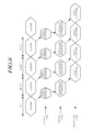
- the touch sensing process of the touch sensing system 100 according to an exemplary embodiment shown in FIG. 6 .
- FIG. 6 is a view illustrating the touch sensing process of the touch sensing system 100 according to an exemplary embodiment.
- the sensing data should be sequentially transmitted from the two or more touch ICs 120 to the controller 140.
- a considerable time delay may be generated in transmitting all of the sensing data from the two or more touch ICs 120 to the controller 140. Therefore, a time for processing a touch sensing increases.
- each of the two or more touch ICs 120 transmits the sensing information to the bridge 130 without consideration of the sensing data transmission timing of another touch IC 120, after each of the two or more touch ICs 120 senses the sensing information with respect to the sensor nodes of each of the two or more touch ICs 120. That is, the bridge 130 simultaneously receives the sensing data from each of the two or more touch ICs 120 in parallel.
- the bridge 130 may receive all of the sensing data in a shorter time in comparison with a case wherein the brige 130 sequentially receives the sensing data from each of the two or more touch ICs 120.
- the bridge 130 again aligns the sensing data received in parallel based on the position of the sensor node and transmits the sensing data.
- the bridge 130 enables the controller 140 to perform the touch algorithm in a shorter time.
- each of the two or more ICs 120 performs a sensing operation for an (N+1)th touch sensing process unrelated to a data transmission (i.e., a bridge parallel transmission) for an Nth touch sensing process.
- the sensing data aligned in the bridge 130 may be transferred to the controller 140 in the type in which the sensing data directly transferred to the controller 140.
- the sensing data may be stored in the shared memory to which all of the bridge 130 and the controller 140 access and transferred to the controller 140 in the read type.
- a method for transferring the sensing data using the shared memory is described in more datail with reference to FIGs. 7 to 10 .
- FIG. 7 is a view illustrating a structure of the shared memory in the touch sensing system 100 according to an exemplary embodiment.
- the touch sensing system 100 may further include the shared memory 150 storing the sensing data 400 transmitted from the bridge 130 and read by the controller 140.
- the bridge 130 in the touch sensing system 100 may be implemented with a Field Programmable Gate Array (FPGA) or may be implemented with a chip made with an Application Specific Integrated Circuit (ASIC) type.
- FPGA Field Programmable Gate Array
- ASIC Application Specific Integrated Circuit
- the FPGA may be an IC capable of changing a circuit several times and programming the changed circuit again.
- the controller 140 in the touch sensing system 100 may be a Central Process Unit (CPU) performing the touch algorithm.
- CPU Central Process Unit
- each of the bridge 130 and the controller 140 should operate separate memories.
- procedures of reading, writing and copying the sensing data are frequently generated, in addition to a problem of including the separate memories.
- the bridge 130 stores the sensing data in a memory 1 (only the bridge 130 may access to the memory 1), when a sensing data is requested from the controller 140 and the sensing data is read from the memory 1 and is transmitted to the controller 140, the controller 140 stores (i.e., copies) the sensing data received from the bridge 130 in a memory (only the controller 140 may access the memory), and the controller 140 should read the sensing data when the controller 140 performs the touch algorithm.
- the controller 140 should read the sensing data when the controller 140 performs the touch algorithm.
- the touch sensing system 100 further includes the shared memory 150 to which all of the bridge 130 and the controller 140 may access, therefore the procedures of reading, writing and copying the sensing data may be removed or decreased, and thus the faster touch process is possible.
- each of the two or more touch ICs 120 determines whether the touch is generated in the areas on the touch panel 110 managed by each of the two or more touch ICs 120 in advance, and informs the result (i.e., touch generation or non-generation determination information). Therefore, the controller 140 may detect the touch coordinate, by using only the sensing data 420 with respect to the partial area, rather than the sensing data with respect to all of the areas on the touch panel 110, based on the touch generation or non-generation determination information 4100, 4200, 4300 and 4400 or the touch IC tag 4000 corresponding to the touch generation or non-generation determination information 4100, 4200, 4300 and 4400.
- the sensing data amount which should be read decreases, and there is an effect of increasing a process speed of the touch algorithm by the decrease in the read sensing data amount.
- the bridge 130 and the controller 140 which are two masters use the shared memory 150 which is one slave, therefore a parallel input/output collision may be generated.
- the bridge 130 and the controller 140 which are the two masters exchange a possessory right (i.e., an authority) signal accessing to the shared memory 150 to use the shared memory 150 which is the one slave. Therefore, the touch sensing system 100 may control not to generate the parallel input/output collision.
- the bridge 130 and the controller 140 which are the two masters may exchange the possessory right signal for controlling a possessory right with respect to the shared memory 150.
- the possessory right signal is a signal informing which of the bridge 130 and the controller 140 which are the two masters has the possessory right with respect to the shared memory 150, and the possessory right signal is a kind of an interrupt signal.
- the touch sensing system 100 may include a switching element switching a connection to the shared memory 150 from the bridge 130 and the controller 140 so that only one of the bridge 130 and the controller 140 accesses to the shared memory 150 at one time point according to the possessory right signal.
- the switching element may be included in each of the bridge 130 and the controller 140. Alternatively the switching element may be disposed outside the bridge 130 and the controller 140.
- a bidirectional possessory right signal transmission method in which each one of the bridge 130 and the controller 140 which are the two masters transmits only own possessory right signal to another of the bridge 130 and the controller 140, may be used.
- a unidirectional possessory right signal transmission method in which only one (e.g., the bridge 130) of the bridge 130 and the controller 140 which are the two masters transmits the possessory right signal to another (e.g., the controller 140) of the bridge 130 and the controller 140, may be used.
- FIG. 8 is a view illustrating the method for controlling the possessory right with respect to the shared memory 150 of the touch sensing system 100 according to an exemplary embodiment.
- FIG. 8 is a view illustrating the case wherein the method for controlling the possessory right with respect to the shared memory 150 is the bidirectional possessory right signal transmission method in which each of one of the bridge 130 and the controller 140 which are the two masters transmits the only own possessory right signal to another of the bridge 130 and the controller 140.
- each of the bridge 130 and the controller 140 which are the two masters uses the own possessory right signal.
- one of the bridge 130 and the controller 140 transmits the own possessory right signal to another of the bridge 130 and the controller 140, and then accesses to the shared memory 150.
- a signal line through which a possessory right signal HOLD1 of the bridge 130 is transferred to the controller 140, and a signal line through which a possessory right signal HOLD2 of the controller 140 is transferred to the bridge 130 may be formed, between the bridge 130 and the controller 140.
- the bridge 130 includes a switching element 810 switching to the shared memory 150 according to whether the bridge 130 possesses the shared memory 150, a processing unit 820 performing a reception, an alignment, a transmission (i.e., a writing) and so on of the sensing data, etc.
- the controller 140 includes a switching element 830 switching to the shared memory 150 according to whether the controller 140 possesses the shared memory 150, a processing unit 840 performing a reading (i.e., a reception), the touch algorithm and so on of the sensing data, etc.
- the bridge 130 transmits the own possessory right signal HOLD 1 to the controller 140, when there is the sensing data to be written to the shared memory 150.
- the switching element 810 included in the bridge 130 or the outside of the bridge 130 turns on so that the processing unit 820 of the bridge 130 is connected to the shared memory 150.
- the switching element 830 included in the controller 140 or the outside of the controller 140 turns off so that the processing unit 840 of the controller 140 is not connected to the shared memory 150.
- the bridge 130 accesses to the shared memory 150 and uses the shared memory 150.
- the bridge 130 stores (i.e., writes) the sensing data to the shared memory 150.
- the controller 140 transmits the own possessory right signal HOLD2 to the bridge 130, when there is the sensing data (i.e., the whole of the sensing data 400 or the portion of the sensing data 420 stored in the shared memory 150) to be read from the shared memory 150.
- the sensing data i.e., the whole of the sensing data 400 or the portion of the sensing data 420 stored in the shared memory 150
- the switching element 830 included in the controller 140 or the outside of the controller 140 turns on so that the processing unit 840 of the controller 140 is connected to the shared memory 150.
- the switching element 810 included in the bridge 130 or the outside of the bridge 130 turns off so that the procesing unit 820 of the bridge 130 is not connected to the shared memory 150.
- the controller 140 accesses to the shared memory 150 and uses the shared memory 150.
- the controller 140 reads the sensing data (i.e., the whole of the sensing data 400 or the portion of the sensing data 420 stored in the shared memory 150) stored in the shared memory 150.
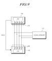
- FIG. 9 is a view illustrating another example of the method for controlling the possessory right with respect to the shared memory 150 of the touch sensing system 100 according to an exemplary embodiment.
- FIG. 9 is a view illustrating the case wherein the method for controlling the possessory right with respect to the shared memory 150 is the unidirectional possessory right signal transmission method in which only one of the bridge 130 and the controller 140 which are the two masters transmits the possessory right signal to another of the bridge 130 and the controller 140.
- the bridge 130 and the controller 140 which are the two masters transmits the possessory right signal.
- the bridge 130 may transmit the possessory right signal
- the controller 140 may only receive the possessory right signal.
- the bridge 130 among the bridge 130 and the controller 140 transmits the possessory right signal to the controller 140, and then the bridge 130 accesses to the shared memory 150.
- the controller 140 may accesses to the shared memory 150, when the bridge 130 does not transmit the possessory right signal.
- the signal line through which the possessory right signal HOLD is transferred from the bridge 130 to the controller 140, between the bridge 130 and the controller 140.
- the bridge 130 includes the switching element 810 switching to the shared memory 150 according to whether the bridge 130 possesses the shared memory 150, the processing unit 820 performing the reception, the alignment, the transmission (i.e., the writing) and so on of the sensing data, etc.
- the controller 140 includes the switching element 830 switching to the shared memory 150 according to whether the controller 140 possesses the shared memory 150, the processing unit 840 performing the reading (i.e., the reception), the touch algorithm and so on of the sensing data, etc.
- the bridge 130 transmits the possessory right signal HOLD to the controller 140, when there is the sensing data to be writed to the shared memory 150.
- the switching element 810 included in the bridge 130 or the outside of the bridge 130 turns on so that the processing unit 820 of the bridge 130 is connected to the shared memory 150.
- the switching element 830 included in the controller 140 or the outside of the controller 140 turns off so that the processing unit 840 of the controller 140 is not connected to the shared memory 150.
- the bridge 130 accesses to the shared memory 150 and uses the shared memory 150.
- the bridge 130 accesses to the shared memory to store (i.e., write) the sensing data in the shared memory 150.
- the controller 140 may access to the shared memory 150 when the bridge 130 does not transmit the possessory right signal after checking whether the bridge 130 transmits the possessory right signal, when there is the sensing data (i.e., the whole of the sensing data 400 or the portion of the sensing data 420 stored in the shared memory 150) to be read from the shared memory 150.
- the sensing data i.e., the whole of the sensing data 400 or the portion of the sensing data 420 stored in the shared memory 150
- the switching element 830 included in the controller 140 or the outside of the controller 140 turns on so that the processing unit 840 of the controller 140 is connected to the shared memory 150.
- the switching element 810 included in the bridge 130 or the outside of the bridge 130 turns off so that the procesing unit 820 of the bridge 130 is not connected to the shared memory 150. That is, the switching element 810 of the bridge 130 turns on only when the bridge 130 transmits the possessory right signal.
- the controller 140 accesses to the shared memory 150 and uses the shared memory 150.
- the controller 140 reads the sensing data (i.e., the whole of the sensing data 400 or the portion of the sensing data 420 stored in the shared memory 150) stored in the shared memory 150.
- the sensing data storing (writing) operation of the bridge 130 is more important than the sensing data reading operation of the controller 140.
- a time of the sensing data storing (writing) operation of the bridge 130 is shorter than a time of the sensing data reading operation of the controller 140. Therefore, a priority of the possessory right with repsect to the shared memory 150 of the bridge 130 may be higher than a priority of the possessory right with respect to the shared memory 150 of the controller 140.
- the bridge 130 may first possess the shared memory 150 having the higher priority of the possessory right with respect to the shared memory 150.
- the bridge 130 may directly control the switching element 830 of the controller 140 so that the controller 140 is not connected to the shared memory 150.
- the bridge 130 may inform the reception of the possessory right signal of the controller 140 to the controller 140 at a point of time when the bridge 130 transmits the own possessory right signal so that the controller 140 is not connected to the shared memory 150 by the switching element 830.
- FIG. 10 is a view illustrating the touch sensing process according to the control of the possessory right with respect to the shared memory 150 of the touch sensing system 100 according to an exemplary embodiment.
- a period when the possessory right signal is a high level is a period (i.e., a bridge possession period) when the bridge 130 possesses the shared memory 150.
- a period when the possessory right signal is a low level is a period (i.e., a controller possession period) when the controller 140 possesses the shared memory 150.
- the bridge 130 accesses to the shared memory 150 and stores the sensing data during the bridge possession period (this operation is shown as 'S' in FIG. 10 ).
- the controller 140 accesses to the shared memory 150, reads the stored sensing data and performs the touch algorithm in the controller possession period.
- the bridge 130 reads and aligns the sensing data transmitted from two or more touch ICs 120.
- the two or more touch ICs 120, the bridge 130 and the controller 140 included in the touch sensing system 100 may be formed on a Printed Circuit Board (PCB) attached to the touch panel 110.
- PCB Printed Circuit Board
- the bridge 130 may be implemented with the Field Programmable Gate Array (FPGA) or may be implemented with a chip made with the Application Specific Integrated Circuit (ASIC) type.
- FPGA Field Programmable Gate Array
- ASIC Application Specific Integrated Circuit
- the FPGA may be the IC capable of changing the circuit several times and programming the changed circuit again.
- the bridge 130 may include digital logic units of which a number is identical to a number of the touch ICs 120. Each of the digital logic units may receive the sensing data by a serial communication (e.g., an I2C, an SPI and so on) with the one touch IC 120.
- a serial communication e.g., an I2C, an SPI and so on
- controller 140 may be implemented with a Central Process Unit (CPU) and so on performing the touch algorithm, may be a CPU having a type of a DSP, an ARM, a MIPS Core and so on, but is not limited thereto, and the controller 140 may be implemented with any other type.
- CPU Central Process Unit
- the controller 140 may be implemented with any other type.
- the two or more touch ICs 120 may be implemented in an on-chip type.
- the two or more touch ICs 120 may be implemented in a type in which the two or more touch ICs 120 are divided into a driving unit driving the driving electrodes, a receiving unit receiving the information from the sensing electrodes and a main CPU IC sensing the sensing informaiton (e.g., the capacitance change and so on) of each of the sensor nodes based on the information received from the receiving unit.
- the touch sensing system 100 may be included in a display apparatus having a display panel, and such a display apparatus is schematically shown in FIG. 11 .
- FIG. 11 is a view illustrating a display apparatus 1100 according to an exemplary embodiment.
- the display apparatus 1100 includes the touch panel 110, a PCB 1110 attached to a side of the touch panel 110, etc.
- the two or more touch ICs 120 sensing the sensor nodes and transmitting the sensing data, the bridge 130 aligning and transmitting the sensing data transmitted from each of the two or more touch ICs 120 and the controller 140 detecting the touch coordinate based on the sensing data transmitted from the bridge 130 are formed on the PCB 1110.
- the PCB 1110 shown in FIG. 11 may be a Flexible Printed Circuit Board (FPCB).
- FPCB Flexible Printed Circuit Board
- the display apparatus further includes a display panel 1120, for example, such as a Liquid Crystal Display (LCD) panel, an Organic Light Emitting Diode (OLED) panel and so on.
- a display panel 1120 for example, such as a Liquid Crystal Display (LCD) panel, an Organic Light Emitting Diode (OLED) panel and so on.
- LCD Liquid Crystal Display
- OLED Organic Light Emitting Diode
- the touch panel 110 shown in FIG. 11 is also referred to as a Touch Screen Panel (TSP).
- TSP Touch Screen Panel
- the touch panel 110 may be attached on the display panel 1120 in an add-on type.
- the touch panel 110 may be included in the display panel 1120 in an on-cell type or an in-cell type.
- an additional configuration referred to as the bridge 130, for aligning and combining the sensing data is disposed between the touch ICs 120 and the controller 140.
- a high speed of a touch sensing process is possible owing to a determining of the touch generation or non-generation in advance and a following partial reading of the sensing data.
- a touch sensing system enabling the high speed of a touch sensing process owing to the determining of the touch generation or non-generation in advance and the following partial reading of the sensing data is schematically described with reference to FIG. 12 .
- the touch sensing system 1200 may include a touch panel 1210 including the driving electrodes Tx1 to TxN and the sensing electrodes Rx1 to RxM defining the sensor nodes, two or more touch ICs 1220 sensing the sensing information of each of the corresponding sensor nodes from the connected sensing electrodes among the sensing electrodes Rx1 to RxM by sequentially driving the driving electrodes Tx1 to TxN, transmitting the sensing data including the sensed sensing information of each of the corresponding sensor nodes, and transmitting the touch generation or non-generation information determined in each of the sensor nodes defined by the connected sensing electrodes or the touch IC tag corresponding to the touch generation or non-generation information, a controller 1230 detecting the touch coordinate based on only the portion of the sensing data among the whole of the sensing data transmitted from each of the two or more touch ICs 1220 and based on the touch generation or non-generation information or the touch IC tags respectively corresponding to the two or more
- the touch sensing system 1200 may further include a shared memory 1240.
- the shared memory 1240 stores the sensing data transmitted from the two or more touch ICs and the touch generation or non-generation information or the touch IC tag corresponding to the touch generation or non-generation information.
- the controller 1230 reads only the portion of the sensing data among the whole of the sensing data transmitted from the two or more touch ICs 1220 and stored in the shared memory 1240.
- the touch sensing system 1200 does not include the bridge 130 according to an exemplary embodiment. Therefore, merely the two or more touch ICs 1220 and/or the controller 1230 share the functions and roles (the alignment and combination of the sensing data) of the bridge 130, and functions, roles and so on of the touch panel 1210, the two or more touch ICs 1220 and the controller 1230 included in the touch sensing system 1200 according to another exemplary embodiment are identical to the functions, roles and so on of the touch panel 110, the two or more touch ICs 120 and the controller 140 included in the touch sensing system 100 according to an exemplary embodiment.
- a display apparatus including the touch sensing system 1200 also merely does not include the bridge configuration, and may be implemented identically to the display apparatus 1100 according to an exemplary embodiment shown in FIG. 11 .
- the present invention there is the effect of providing the touch sensing system 100 or 1200 decreasing a sensing time and enabling an effective touch sensing, although a number of the sensing electrodes increases according to an increase of an area of the touch panel 110 or 1210, and the display apparatus including the touch sensing system 100 or 1200.
- the present invention there is the effect of providing the touch sensing system 100 or 1200 performing an effective sensing process through the Rx division sensing method partitively sensing the sensing electrodes, when the number of the sensing electrodes increases according to the increase of the area of the touch panel 110 or 1210, and the display apparatus including the touch sensing system 100 or 1200.
- the bridge 130 As the additional configuration receiving the divided and sensed sensing data from the two or more touch ICs 120 in parallel, assigning and combining the received sensing data, among the two or more touch ICs 120 and the controller 140 performing the touch algorithm is further disclosed. Therefore, delays of the sensing data transmission and the touch algorithm performance, rather may be generated by the Rx division sensing method suggested for increasing the effectiveness of the touch sensing when the number of the sensing electrodes increases according to the increase of the area of the touch panel 110, decrease. Thus, there is the effect of enabling high speed of sensing data transmission and touch algorithm performance.
- an input/output (I/O) collision may be generated according to memory uses of each of the controller 140 and the bridge 130.
- the number of the sensing electrodes increases due to the increase of the area of the touch panel 110, the sensing data amount stored in the memory and read from the memory increases.
- the touch coordinate is detected with respect to the only partial area where it is determined that the touch is generated rather than the whole area on the touch panel 110 or 1210.
- only a necessary sensing data is read partially, therefore there is the effect of decreasing the amount of the sensing data which should be read by the controller 140 or 1230 and enabling the controller 140 or 1230 to process the touch algorithm faster.
Landscapes
- Engineering & Computer Science (AREA)
- General Engineering & Computer Science (AREA)
- Theoretical Computer Science (AREA)
- Human Computer Interaction (AREA)
- Physics & Mathematics (AREA)
- General Physics & Mathematics (AREA)
- Position Input By Displaying (AREA)
Applications Claiming Priority (1)
| Application Number | Priority Date | Filing Date | Title |
|---|---|---|---|
| KR1020130133404A KR102114488B1 (ko) | 2013-11-05 | 2013-11-05 | 터치센싱시스템 및 표시장치 |
Publications (2)
| Publication Number | Publication Date |
|---|---|
| EP2869168A1 true EP2869168A1 (fr) | 2015-05-06 |
| EP2869168B1 EP2869168B1 (fr) | 2019-03-20 |
Family
ID=51392106
Family Applications (1)
| Application Number | Title | Priority Date | Filing Date |
|---|---|---|---|
| EP14181887.2A Active EP2869168B1 (fr) | 2013-11-05 | 2014-08-22 | Système de détection tactile et appareil d'affichage |
Country Status (6)
| Country | Link |
|---|---|
| US (1) | US9678611B2 (fr) |
| EP (1) | EP2869168B1 (fr) |
| JP (1) | JP5989051B2 (fr) |
| KR (1) | KR102114488B1 (fr) |
| CN (1) | CN104615297B (fr) |
| TW (1) | TWI549029B (fr) |
Cited By (1)
| Publication number | Priority date | Publication date | Assignee | Title |
|---|---|---|---|---|
| WO2019143770A1 (fr) * | 2018-01-18 | 2019-07-25 | Elo Touch Solutions, Inc. | Grand écran à technologie capacitive projetée avec de multiples circuits intégrés spécifiques à une application de commande tactile avec connexions de récepteur entrelacées |
Families Citing this family (24)
| Publication number | Priority date | Publication date | Assignee | Title |
|---|---|---|---|---|
| US8633915B2 (en) | 2007-10-04 | 2014-01-21 | Apple Inc. | Single-layer touch-sensitive display |
| US20090174676A1 (en) | 2008-01-04 | 2009-07-09 | Apple Inc. | Motion component dominance factors for motion locking of touch sensor data |
| US8922521B2 (en) | 2009-02-02 | 2014-12-30 | Apple Inc. | Switching circuitry for touch sensitive display |
| US8593410B2 (en) | 2009-04-10 | 2013-11-26 | Apple Inc. | Touch sensor panel design |
| US8957874B2 (en) | 2009-06-29 | 2015-02-17 | Apple Inc. | Touch sensor panel design |
| US9329723B2 (en) | 2012-04-16 | 2016-05-03 | Apple Inc. | Reconstruction of original touch image from differential touch image |
| US9886141B2 (en) | 2013-08-16 | 2018-02-06 | Apple Inc. | Mutual and self capacitance touch measurements in touch panel |
| WO2015178920A1 (fr) | 2014-05-22 | 2015-11-26 | Onamp Research Llc | Architectures d'amorçage de panneau pour capacité propre en cellule |
| US10289251B2 (en) | 2014-06-27 | 2019-05-14 | Apple Inc. | Reducing floating ground effects in pixelated self-capacitance touch screens |
| US9880655B2 (en) | 2014-09-02 | 2018-01-30 | Apple Inc. | Method of disambiguating water from a finger touch on a touch sensor panel |
| CN107077260B (zh) | 2014-09-22 | 2020-05-12 | 苹果公司 | 触摸控制器和用于触摸传感器面板的方法 |
| US10712867B2 (en) | 2014-10-27 | 2020-07-14 | Apple Inc. | Pixelated self-capacitance water rejection |
| KR20160085126A (ko) * | 2015-01-07 | 2016-07-15 | 삼성전자주식회사 | 전자 장치 및 전자 장치의 터치 스캔 방법 |
| AU2016215616B2 (en) | 2015-02-02 | 2018-12-06 | Apple Inc. | Flexible self-capacitance and mutual capacitance touch sensing system architecture |
| US10488992B2 (en) | 2015-03-10 | 2019-11-26 | Apple Inc. | Multi-chip touch architecture for scalability |
| US10365773B2 (en) | 2015-09-30 | 2019-07-30 | Apple Inc. | Flexible scan plan using coarse mutual capacitance and fully-guarded measurements |
| AU2017208277B2 (en) | 2016-09-06 | 2018-12-20 | Apple Inc. | Back of cover touch sensors |
| US10642418B2 (en) | 2017-04-20 | 2020-05-05 | Apple Inc. | Finger tracking in wet environment |
| JP2019179334A (ja) * | 2018-03-30 | 2019-10-17 | ルネサスエレクトロニクス株式会社 | 半導体装置、その制御方法、及び、接続関係設定処理プログラム |
| TWI814729B (zh) * | 2018-06-25 | 2023-09-11 | 李尚禮 | 觸控辨識裝置之感測方法及其感測模組 |
| CN109388284B (zh) * | 2018-09-17 | 2024-01-02 | 深圳市德明利技术股份有限公司 | 一种触控装置、移动终端及信号处理方法 |
| US11662867B1 (en) | 2020-05-30 | 2023-05-30 | Apple Inc. | Hover detection on a touch sensor panel |
| KR102880070B1 (ko) * | 2020-11-12 | 2025-11-03 | 엘지디스플레이 주식회사 | 터치 디스플레이 장치, 터치 구동 회로 및 터치 구동 방법 |
| US11520430B2 (en) | 2021-01-29 | 2022-12-06 | Himax Technologies Limited | Touch signal processing method and related touch device |
Citations (5)
| Publication number | Priority date | Publication date | Assignee | Title |
|---|---|---|---|---|
| US20080042992A1 (en) * | 2006-08-18 | 2008-02-21 | Samsung Electronics, Co., Ltd. | Touch screen display apparatus and method fof driving the same |
| US20090250269A1 (en) * | 2008-04-02 | 2009-10-08 | Tse-Lun Hung | Capacitive touch system and data transmission method in a capacitive touch system |
| US20090251437A1 (en) * | 2008-04-02 | 2009-10-08 | Tse-Lun Hung | Capacitive touch system and control method for a capacitive touch system |
| US20110242015A1 (en) * | 2010-03-30 | 2011-10-06 | Hon Hai Precision Industry Co., Ltd. | Touch input device |
| US20130278525A1 (en) * | 2012-04-24 | 2013-10-24 | Lg Display Co., Ltd | Touch screen driver |
Family Cites Families (12)
| Publication number | Priority date | Publication date | Assignee | Title |
|---|---|---|---|---|
| KR100881186B1 (ko) * | 2007-01-04 | 2009-02-05 | 삼성전자주식회사 | 터치 스크린 디스플레이 장치 |
| KR101383709B1 (ko) * | 2007-03-07 | 2014-04-09 | 삼성디스플레이 주식회사 | 표시 장치 및 그의 구동 방법 |
| US8519965B2 (en) * | 2008-04-23 | 2013-08-27 | Motorola Mobility Llc | Multi-touch detection panel with disambiguation of touch coordinates |
| JP2010191730A (ja) * | 2009-02-19 | 2010-09-02 | Gunze Ltd | タッチ処理装置 |
| WO2011075608A2 (fr) * | 2009-12-18 | 2011-06-23 | Synaptics Incorporated | Dispositifs de détection transcapacitifs avec soudures ohmiques |
| US8310380B2 (en) * | 2010-03-02 | 2012-11-13 | Invensense Inc. | Selectable communication interface configurations for motion sensing device |
| CN102402316B (zh) * | 2010-09-07 | 2015-04-15 | 群康科技(深圳)有限公司 | 触控面板的感测值辨识方法与驱动装置 |
| JP2013020479A (ja) | 2011-07-12 | 2013-01-31 | Panasonic Corp | タッチパネル装置 |
| CN102999471B (zh) | 2011-09-09 | 2015-11-04 | 中国科学院声学研究所 | 一种多处理器共享非易失性存储卡的方法及系统 |
| TWI451306B (zh) * | 2011-12-02 | 2014-09-01 | Mstar Semiconductor Inc | 觸控感測裝置及觸控感測設備以及其觸控感測方法 |
| GB2499242A (en) * | 2012-02-10 | 2013-08-14 | Alterix Ltd | methods of operating excitation circuitry and/or measurement circuitry in a digitiser and a method of manufacturing a transducer for a digitiser |
| US8884906B2 (en) * | 2012-12-21 | 2014-11-11 | Intel Corporation | Offloading touch processing to a graphics processor |
-
2013
- 2013-11-05 KR KR1020130133404A patent/KR102114488B1/ko active Active
-
2014
- 2014-08-15 US US14/461,145 patent/US9678611B2/en active Active
- 2014-08-22 EP EP14181887.2A patent/EP2869168B1/fr active Active
- 2014-09-04 TW TW103130626A patent/TWI549029B/zh active
- 2014-09-22 CN CN201410486051.XA patent/CN104615297B/zh active Active
- 2014-09-22 JP JP2014192243A patent/JP5989051B2/ja active Active
Patent Citations (5)
| Publication number | Priority date | Publication date | Assignee | Title |
|---|---|---|---|---|
| US20080042992A1 (en) * | 2006-08-18 | 2008-02-21 | Samsung Electronics, Co., Ltd. | Touch screen display apparatus and method fof driving the same |
| US20090250269A1 (en) * | 2008-04-02 | 2009-10-08 | Tse-Lun Hung | Capacitive touch system and data transmission method in a capacitive touch system |
| US20090251437A1 (en) * | 2008-04-02 | 2009-10-08 | Tse-Lun Hung | Capacitive touch system and control method for a capacitive touch system |
| US20110242015A1 (en) * | 2010-03-30 | 2011-10-06 | Hon Hai Precision Industry Co., Ltd. | Touch input device |
| US20130278525A1 (en) * | 2012-04-24 | 2013-10-24 | Lg Display Co., Ltd | Touch screen driver |
Cited By (3)
| Publication number | Priority date | Publication date | Assignee | Title |
|---|---|---|---|---|
| WO2019143770A1 (fr) * | 2018-01-18 | 2019-07-25 | Elo Touch Solutions, Inc. | Grand écran à technologie capacitive projetée avec de multiples circuits intégrés spécifiques à une application de commande tactile avec connexions de récepteur entrelacées |
| US10503312B2 (en) | 2018-01-18 | 2019-12-10 | Elo Touch Solutions, Inc. | Large PCAP screen with multiple touch controller ASICS with interleaved receiver connections |
| US10936115B2 (en) | 2018-01-18 | 2021-03-02 | Elo Touch Solutions, Inc. | Large PCAP screen with multiple touch controller ASICs with interleaved connections |
Also Published As
| Publication number | Publication date |
|---|---|
| US9678611B2 (en) | 2017-06-13 |
| CN104615297B (zh) | 2018-06-22 |
| TWI549029B (zh) | 2016-09-11 |
| TW201519047A (zh) | 2015-05-16 |
| KR20150052430A (ko) | 2015-05-14 |
| EP2869168B1 (fr) | 2019-03-20 |
| CN104615297A (zh) | 2015-05-13 |
| JP2015090706A (ja) | 2015-05-11 |
| US20150123939A1 (en) | 2015-05-07 |
| KR102114488B1 (ko) | 2020-05-25 |
| JP5989051B2 (ja) | 2016-09-07 |
Similar Documents
| Publication | Publication Date | Title |
|---|---|---|
| EP2869168B1 (fr) | Système de détection tactile et appareil d'affichage | |
| US9939959B2 (en) | Multi-touch integrity sensing for capacitive touch screen | |
| US11194420B2 (en) | Device and method for proximity sensing for display panel having a variable display frame rate | |
| US20090255737A1 (en) | Device and Method for Preventing the Influence of Conducting Material from Point Detection of Projected Capacitive Touch Panel | |
| US20140176486A1 (en) | Touch screen and method for driving the same | |
| US10445285B2 (en) | Integrated data concentrator for multi-sensor MEMS systems | |
| CN104699335A (zh) | 混合型电容性触摸系统设计 | |
| US20120249446A1 (en) | Touch-sensing apparatus | |
| US8686735B2 (en) | Input device receiver path and transmitter path error diagnosis | |
| US20200192449A1 (en) | Bus system | |
| CN103543874A (zh) | 触摸传感器控制器传感器集线器 | |
| CN115079865B (zh) | 一种触控面板及触控方法、装置、设备 | |
| US20210157434A1 (en) | Device and method for proximity sensing on an input device | |
| US8654089B2 (en) | Touch sensing circuit and touch sensing method | |
| CN104076979B (zh) | 电子设备、应用执行器件、电子设备的控制方法 | |
| CN105467699B (zh) | 带有传感器的显示装置以及显示装置的控制方法 | |
| US9811229B2 (en) | Capacitive touch sensing | |
| US20130249856A1 (en) | Touch device and touch sensing method thereof | |
| US20110148765A1 (en) | Optical mouse soc with 8-pins | |
| WO2014163906A1 (fr) | Elimination du bruit de mode commun dans des applications tactiles | |
| US9652422B2 (en) | Multi-bus system | |
| Choi et al. | Distributed architecture of touch screen controller SoC for large touch screen panels | |
| KR20190005344A (ko) | 지문 검출을 위한 터치 스크린 | |
| JP6241216B2 (ja) | センサーデバイス、センサーユニット及び電子機器 | |
| CN104251716B (zh) | 媒介保管盒检测装置 |
Legal Events
| Date | Code | Title | Description |
|---|---|---|---|
| PUAI | Public reference made under article 153(3) epc to a published international application that has entered the european phase |
Free format text: ORIGINAL CODE: 0009012 |
|
| 17P | Request for examination filed |
Effective date: 20140822 |
|
| AK | Designated contracting states |
Kind code of ref document: A1 Designated state(s): AL AT BE BG CH CY CZ DE DK EE ES FI FR GB GR HR HU IE IS IT LI LT LU LV MC MK MT NL NO PL PT RO RS SE SI SK SM TR |
|
| AX | Request for extension of the european patent |
Extension state: BA ME |
|
| R17P | Request for examination filed (corrected) |
Effective date: 20151106 |
|
| RBV | Designated contracting states (corrected) |
Designated state(s): AL AT BE BG CH CY CZ DE DK EE ES FI FR GB GR HR HU IE IS IT LI LT LU LV MC MK MT NL NO PL PT RO RS SE SI SK SM TR |
|
| GRAP | Despatch of communication of intention to grant a patent |
Free format text: ORIGINAL CODE: EPIDOSNIGR1 |
|
| STAA | Information on the status of an ep patent application or granted ep patent |
Free format text: STATUS: GRANT OF PATENT IS INTENDED |
|
| INTG | Intention to grant announced |
Effective date: 20180903 |
|
| RAP1 | Party data changed (applicant data changed or rights of an application transferred) |
Owner name: LG DISPLAY CO., LTD. |
|
| GRAS | Grant fee paid |
Free format text: ORIGINAL CODE: EPIDOSNIGR3 |
|
| GRAA | (expected) grant |
Free format text: ORIGINAL CODE: 0009210 |
|
| STAA | Information on the status of an ep patent application or granted ep patent |
Free format text: STATUS: THE PATENT HAS BEEN GRANTED |
|
| AK | Designated contracting states |
Kind code of ref document: B1 Designated state(s): AL AT BE BG CH CY CZ DE DK EE ES FI FR GB GR HR HU IE IS IT LI LT LU LV MC MK MT NL NO PL PT RO RS SE SI SK SM TR |
|
| REG | Reference to a national code |
Ref country code: GB Ref legal event code: FG4D |
|
| REG | Reference to a national code |
Ref country code: CH Ref legal event code: EP |
|
| REG | Reference to a national code |
Ref country code: DE Ref legal event code: R096 Ref document number: 602014043163 Country of ref document: DE |
|
| REG | Reference to a national code |
Ref country code: AT Ref legal event code: REF Ref document number: 1111198 Country of ref document: AT Kind code of ref document: T Effective date: 20190415 |
|
| REG | Reference to a national code |
Ref country code: IE Ref legal event code: FG4D |
|
| REG | Reference to a national code |
Ref country code: NL Ref legal event code: MP Effective date: 20190320 |
|
| PG25 | Lapsed in a contracting state [announced via postgrant information from national office to epo] |
Ref country code: SE Free format text: LAPSE BECAUSE OF FAILURE TO SUBMIT A TRANSLATION OF THE DESCRIPTION OR TO PAY THE FEE WITHIN THE PRESCRIBED TIME-LIMIT Effective date: 20190320 Ref country code: NO Free format text: LAPSE BECAUSE OF FAILURE TO SUBMIT A TRANSLATION OF THE DESCRIPTION OR TO PAY THE FEE WITHIN THE PRESCRIBED TIME-LIMIT Effective date: 20190620 Ref country code: FI Free format text: LAPSE BECAUSE OF FAILURE TO SUBMIT A TRANSLATION OF THE DESCRIPTION OR TO PAY THE FEE WITHIN THE PRESCRIBED TIME-LIMIT Effective date: 20190320 Ref country code: LT Free format text: LAPSE BECAUSE OF FAILURE TO SUBMIT A TRANSLATION OF THE DESCRIPTION OR TO PAY THE FEE WITHIN THE PRESCRIBED TIME-LIMIT Effective date: 20190320 |
|
| REG | Reference to a national code |
Ref country code: LT Ref legal event code: MG4D |
|
| PG25 | Lapsed in a contracting state [announced via postgrant information from national office to epo] |
Ref country code: GR Free format text: LAPSE BECAUSE OF FAILURE TO SUBMIT A TRANSLATION OF THE DESCRIPTION OR TO PAY THE FEE WITHIN THE PRESCRIBED TIME-LIMIT Effective date: 20190621 Ref country code: NL Free format text: LAPSE BECAUSE OF FAILURE TO SUBMIT A TRANSLATION OF THE DESCRIPTION OR TO PAY THE FEE WITHIN THE PRESCRIBED TIME-LIMIT Effective date: 20190320 Ref country code: LV Free format text: LAPSE BECAUSE OF FAILURE TO SUBMIT A TRANSLATION OF THE DESCRIPTION OR TO PAY THE FEE WITHIN THE PRESCRIBED TIME-LIMIT Effective date: 20190320 Ref country code: HR Free format text: LAPSE BECAUSE OF FAILURE TO SUBMIT A TRANSLATION OF THE DESCRIPTION OR TO PAY THE FEE WITHIN THE PRESCRIBED TIME-LIMIT Effective date: 20190320 Ref country code: BG Free format text: LAPSE BECAUSE OF FAILURE TO SUBMIT A TRANSLATION OF THE DESCRIPTION OR TO PAY THE FEE WITHIN THE PRESCRIBED TIME-LIMIT Effective date: 20190620 Ref country code: RS Free format text: LAPSE BECAUSE OF FAILURE TO SUBMIT A TRANSLATION OF THE DESCRIPTION OR TO PAY THE FEE WITHIN THE PRESCRIBED TIME-LIMIT Effective date: 20190320 |
|
| REG | Reference to a national code |
Ref country code: AT Ref legal event code: MK05 Ref document number: 1111198 Country of ref document: AT Kind code of ref document: T Effective date: 20190320 |
|
| PG25 | Lapsed in a contracting state [announced via postgrant information from national office to epo] |
Ref country code: AL Free format text: LAPSE BECAUSE OF FAILURE TO SUBMIT A TRANSLATION OF THE DESCRIPTION OR TO PAY THE FEE WITHIN THE PRESCRIBED TIME-LIMIT Effective date: 20190320 Ref country code: CZ Free format text: LAPSE BECAUSE OF FAILURE TO SUBMIT A TRANSLATION OF THE DESCRIPTION OR TO PAY THE FEE WITHIN THE PRESCRIBED TIME-LIMIT Effective date: 20190320 Ref country code: ES Free format text: LAPSE BECAUSE OF FAILURE TO SUBMIT A TRANSLATION OF THE DESCRIPTION OR TO PAY THE FEE WITHIN THE PRESCRIBED TIME-LIMIT Effective date: 20190320 Ref country code: RO Free format text: LAPSE BECAUSE OF FAILURE TO SUBMIT A TRANSLATION OF THE DESCRIPTION OR TO PAY THE FEE WITHIN THE PRESCRIBED TIME-LIMIT Effective date: 20190320 Ref country code: IT Free format text: LAPSE BECAUSE OF FAILURE TO SUBMIT A TRANSLATION OF THE DESCRIPTION OR TO PAY THE FEE WITHIN THE PRESCRIBED TIME-LIMIT Effective date: 20190320 Ref country code: EE Free format text: LAPSE BECAUSE OF FAILURE TO SUBMIT A TRANSLATION OF THE DESCRIPTION OR TO PAY THE FEE WITHIN THE PRESCRIBED TIME-LIMIT Effective date: 20190320 Ref country code: PT Free format text: LAPSE BECAUSE OF FAILURE TO SUBMIT A TRANSLATION OF THE DESCRIPTION OR TO PAY THE FEE WITHIN THE PRESCRIBED TIME-LIMIT Effective date: 20190720 Ref country code: SK Free format text: LAPSE BECAUSE OF FAILURE TO SUBMIT A TRANSLATION OF THE DESCRIPTION OR TO PAY THE FEE WITHIN THE PRESCRIBED TIME-LIMIT Effective date: 20190320 |
|
| PG25 | Lapsed in a contracting state [announced via postgrant information from national office to epo] |
Ref country code: PL Free format text: LAPSE BECAUSE OF FAILURE TO SUBMIT A TRANSLATION OF THE DESCRIPTION OR TO PAY THE FEE WITHIN THE PRESCRIBED TIME-LIMIT Effective date: 20190320 Ref country code: SM Free format text: LAPSE BECAUSE OF FAILURE TO SUBMIT A TRANSLATION OF THE DESCRIPTION OR TO PAY THE FEE WITHIN THE PRESCRIBED TIME-LIMIT Effective date: 20190320 |
|
| PG25 | Lapsed in a contracting state [announced via postgrant information from national office to epo] |
Ref country code: IS Free format text: LAPSE BECAUSE OF FAILURE TO SUBMIT A TRANSLATION OF THE DESCRIPTION OR TO PAY THE FEE WITHIN THE PRESCRIBED TIME-LIMIT Effective date: 20190720 Ref country code: AT Free format text: LAPSE BECAUSE OF FAILURE TO SUBMIT A TRANSLATION OF THE DESCRIPTION OR TO PAY THE FEE WITHIN THE PRESCRIBED TIME-LIMIT Effective date: 20190320 |
|
| REG | Reference to a national code |
Ref country code: DE Ref legal event code: R097 Ref document number: 602014043163 Country of ref document: DE |
|
| PLBE | No opposition filed within time limit |
Free format text: ORIGINAL CODE: 0009261 |
|
| STAA | Information on the status of an ep patent application or granted ep patent |
Free format text: STATUS: NO OPPOSITION FILED WITHIN TIME LIMIT |
|
| PG25 | Lapsed in a contracting state [announced via postgrant information from national office to epo] |
Ref country code: DK Free format text: LAPSE BECAUSE OF FAILURE TO SUBMIT A TRANSLATION OF THE DESCRIPTION OR TO PAY THE FEE WITHIN THE PRESCRIBED TIME-LIMIT Effective date: 20190320 |
|
| 26N | No opposition filed |
Effective date: 20200102 |
|
| PG25 | Lapsed in a contracting state [announced via postgrant information from national office to epo] |
Ref country code: SI Free format text: LAPSE BECAUSE OF FAILURE TO SUBMIT A TRANSLATION OF THE DESCRIPTION OR TO PAY THE FEE WITHIN THE PRESCRIBED TIME-LIMIT Effective date: 20190320 |
|
| PG25 | Lapsed in a contracting state [announced via postgrant information from national office to epo] |
Ref country code: TR Free format text: LAPSE BECAUSE OF FAILURE TO SUBMIT A TRANSLATION OF THE DESCRIPTION OR TO PAY THE FEE WITHIN THE PRESCRIBED TIME-LIMIT Effective date: 20190320 |
|
| PG25 | Lapsed in a contracting state [announced via postgrant information from national office to epo] |
Ref country code: LU Free format text: LAPSE BECAUSE OF NON-PAYMENT OF DUE FEES Effective date: 20190822 Ref country code: MC Free format text: LAPSE BECAUSE OF FAILURE TO SUBMIT A TRANSLATION OF THE DESCRIPTION OR TO PAY THE FEE WITHIN THE PRESCRIBED TIME-LIMIT Effective date: 20190320 Ref country code: CH Free format text: LAPSE BECAUSE OF NON-PAYMENT OF DUE FEES Effective date: 20190831 Ref country code: LI Free format text: LAPSE BECAUSE OF NON-PAYMENT OF DUE FEES Effective date: 20190831 |
|
| REG | Reference to a national code |
Ref country code: BE Ref legal event code: MM Effective date: 20190831 |
|
| PG25 | Lapsed in a contracting state [announced via postgrant information from national office to epo] |
Ref country code: IE Free format text: LAPSE BECAUSE OF NON-PAYMENT OF DUE FEES Effective date: 20190822 |
|
| PG25 | Lapsed in a contracting state [announced via postgrant information from national office to epo] |
Ref country code: BE Free format text: LAPSE BECAUSE OF NON-PAYMENT OF DUE FEES Effective date: 20190831 |
|
| PG25 | Lapsed in a contracting state [announced via postgrant information from national office to epo] |
Ref country code: CY Free format text: LAPSE BECAUSE OF FAILURE TO SUBMIT A TRANSLATION OF THE DESCRIPTION OR TO PAY THE FEE WITHIN THE PRESCRIBED TIME-LIMIT Effective date: 20190320 |
|
| PG25 | Lapsed in a contracting state [announced via postgrant information from national office to epo] |
Ref country code: MT Free format text: LAPSE BECAUSE OF FAILURE TO SUBMIT A TRANSLATION OF THE DESCRIPTION OR TO PAY THE FEE WITHIN THE PRESCRIBED TIME-LIMIT Effective date: 20190320 Ref country code: HU Free format text: LAPSE BECAUSE OF FAILURE TO SUBMIT A TRANSLATION OF THE DESCRIPTION OR TO PAY THE FEE WITHIN THE PRESCRIBED TIME-LIMIT; INVALID AB INITIO Effective date: 20140822 |
|
| PG25 | Lapsed in a contracting state [announced via postgrant information from national office to epo] |
Ref country code: MK Free format text: LAPSE BECAUSE OF FAILURE TO SUBMIT A TRANSLATION OF THE DESCRIPTION OR TO PAY THE FEE WITHIN THE PRESCRIBED TIME-LIMIT Effective date: 20190320 |
|
| PGFP | Annual fee paid to national office [announced via postgrant information from national office to epo] |
Ref country code: GB Payment date: 20250624 Year of fee payment: 12 |
|
| PGFP | Annual fee paid to national office [announced via postgrant information from national office to epo] |
Ref country code: FR Payment date: 20250624 Year of fee payment: 12 |
|
| PGFP | Annual fee paid to national office [announced via postgrant information from national office to epo] |
Ref country code: DE Payment date: 20250624 Year of fee payment: 12 |