EP2869507A1 - Verfahren, vorrichtung und system zum routen von sitzungen - Google Patents
Verfahren, vorrichtung und system zum routen von sitzungen Download PDFInfo
- Publication number
- EP2869507A1 EP2869507A1 EP20120879898 EP12879898A EP2869507A1 EP 2869507 A1 EP2869507 A1 EP 2869507A1 EP 20120879898 EP20120879898 EP 20120879898 EP 12879898 A EP12879898 A EP 12879898A EP 2869507 A1 EP2869507 A1 EP 2869507A1
- Authority
- EP
- European Patent Office
- Prior art keywords
- routing device
- address
- terminal
- routing
- data packet
- Prior art date
- Legal status (The legal status is an assumption and is not a legal conclusion. Google has not performed a legal analysis and makes no representation as to the accuracy of the status listed.)
- Withdrawn
Links
- 238000000034 method Methods 0.000 title claims abstract description 30
- 230000002452 interceptive effect Effects 0.000 claims description 22
- 238000004891 communication Methods 0.000 abstract description 8
- 238000005538 encapsulation Methods 0.000 description 12
- 238000010586 diagram Methods 0.000 description 6
- 238000005516 engineering process Methods 0.000 description 5
- 230000005540 biological transmission Effects 0.000 description 2
- 230000006870 function Effects 0.000 description 2
- 238000004590 computer program Methods 0.000 description 1
- 238000012423 maintenance Methods 0.000 description 1
- 230000003287 optical effect Effects 0.000 description 1
- 230000011664 signaling Effects 0.000 description 1
- 238000006467 substitution reaction Methods 0.000 description 1
Images


Classifications
-
- H—ELECTRICITY
- H04—ELECTRIC COMMUNICATION TECHNIQUE
- H04L—TRANSMISSION OF DIGITAL INFORMATION, e.g. TELEGRAPHIC COMMUNICATION
- H04L45/00—Routing or path finding of packets in data switching networks
- H04L45/74—Address processing for routing
-
- H—ELECTRICITY
- H04—ELECTRIC COMMUNICATION TECHNIQUE
- H04W—WIRELESS COMMUNICATION NETWORKS
- H04W8/00—Network data management
- H04W8/02—Processing of mobility data, e.g. registration information at HLR [Home Location Register] or VLR [Visitor Location Register]; Transfer of mobility data, e.g. between HLR, VLR or external networks
- H04W8/08—Mobility data transfer
- H04W8/082—Mobility data transfer for traffic bypassing of mobility servers, e.g. location registers, home PLMNs or home agents
-
- H—ELECTRICITY
- H04—ELECTRIC COMMUNICATION TECHNIQUE
- H04W—WIRELESS COMMUNICATION NETWORKS
- H04W8/00—Network data management
- H04W8/02—Processing of mobility data, e.g. registration information at HLR [Home Location Register] or VLR [Visitor Location Register]; Transfer of mobility data, e.g. between HLR, VLR or external networks
- H04W8/08—Mobility data transfer
- H04W8/12—Mobility data transfer between location registers or mobility servers
-
- H—ELECTRICITY
- H04—ELECTRIC COMMUNICATION TECHNIQUE
- H04W—WIRELESS COMMUNICATION NETWORKS
- H04W88/00—Devices specially adapted for wireless communication networks, e.g. terminals, base stations or access point devices
- H04W88/005—Data network PoA devices
Definitions
- the present invention relates to a field of communications technologies, and in particular, to a method, a device and a system for session routing.
- An MIP Mobile Internet Protocol, mobile internet protocol
- MN Mobile Node, mobile node
- IP Internet Protocol, internet protocol
- the MIP is applied to all networks based on an IP (Internet Protocol, internet protocol).
- each MN belongs to a fixed routing device, namely an LMA (Local Mobility Anchor, local mobility anchor), a network in which the fixed LMA is located is a home network of the MN.
- LMA Local Mobility Anchor
- the MN When the MN enters a visited network from the home network, the MN establishes a transmission link with an MAG (Mobile Access Gateway, mobile access gateway) in the visited network, and the MAG, serving as the defined network entity, establishes a transmission tunnel with the LMA in the home network to which the MN belongs, in order to achieve communication between the MN and a CN (Correspondent Node, correspondent node) which establishes a session in the home network.
- MAG Mobile Access Gateway, mobile access gateway
- each MN belongs to the fixed LMA in the home network, after the MN enters the visited network, all communication traffic needs to be forwarded by the LMA, and when a large number of MN belong to one fixed LMA, a processing load of the LMA in the home network may be quite large.
- Embodiments of the present invention provide a method, a device and a system for session routing, for solving a problem of larger processing load of an LMA in an existing PMIP network.
- a method for session routing including:
- a device for session routing serves as a first routing device and includes:
- a system for session routing including: a first routing device and a second routing device, wherein the first routing device is configured to, when a first terminal enters a first network in which the first routing device is located, obtain an address of the second routing device in a second network, establish a tunnel with the second routing device according to the address of the second routing device, and maintain a session between the first terminal and the second routing device through the tunnel; and the second routing device is configured to route the session to a second terminal in the second network.
- the first routing device when the first terminal enters the first network in which the first routing device is located, the first routing device obtains the address of the second routing device in the second network, the first routing device establishes the tunnel with the second routing device according to the address of the second routing device, and maintains the session between the first terminal and the second routing device through the tunnel, so that the second routing device routes the session to the second terminal in the second network.
- the terminal may no longer belong to a fixed routing device in the home network, when the terminal enters a network, session routing between the terminal and a routing device in other networks is achieved by a routing device to which the terminal is attached in the network, and since the routing device to which the terminal belongs varies with the network in which the terminal is located, the communication traffic of the terminal may not be concentrated on one routing device for forwarding, thus reducing the processing load of a single routing device.
- Fig.1 is a flowchart of an embodiment of a method for session routing in the present invention.
- Step 101 when a first terminal enters a first network in which a first routing device is located, the first routing device obtains an address of a second routing device in a second network.
- the first routing device may obtain the address of the second routing device in the second network in any one of the following modes:
- Step 102 the first routing device establishes a tunnel with the second routing device according to the address of the second routing device.
- the first routing device may adopt the following modes according to the different modes of obtaining the address of the second routing device in step 101.
- a first mode when the address of the second routing device in the second network is obtained in the first mode in step 101, the first routing device obtains the address of the second routing device from the router solicitation message; sends a proxy binding update message to the second routing device according to the address of the second routing device, wherein the proxy binding update message contains an address of the first routing device; after receiving a proxy binding acknowledgement message replied by the second routing device according to the address of the first routing device, stores the address of the second routing device and the IP address information allocated by the second routing device to the first terminal, and finishes the establishing the tunnel with the second routing device.
- a second mode when the address of the second routing device in the second network is obtained in the second mode in step 101, the first routing device obtains the address of the second routing device from the configuration file; sends a proxy binding update message to the second routing device according to the address of the second routing device, wherein the proxy binding update message contains an address of the first routing device; after receiving a proxy binding acknowledgement message replied by the second routing device according to the address of the first routing device, stores the address of the second routing device and the IP address information allocated by the second routing device to the first terminal, and finishes the establishing the tunnel with the second routing device.
- a third mode when the address of the second routing device in the second network is obtained in the third mode in step 101, the first routing device receives a router solicitation message sent by the first terminal, wherein the router solicitation message contains IP address information allocated by the second routing device to the first terminal; when searching out that the IP address information belongs to the IP address information domain of the second routing device, the first routing device obtains the address of the second routing device corresponding to the IP address information domain of the second routing device; sends a proxy binding update message to the second routing device according to the address of the second routing device, wherein the proxy binding update message contains an address of the first routing device; after receiving a proxy binding acknowledgement message replied by the second routing device according to the address of the first routing device, stores the address of the second routing device and the IP address information allocated by the second routing device to the first terminal, and finishes the establishing the tunnel with the second routing device.
- a fourth mode when the address of the second routing device in the second network is obtained in the third mode in step 101, the first routing device receives a data packet transmitted by the first terminal; when searching out that source IP address information of the data packet belongs to the IP address information domain of the second routing device, the first routing device obtains the address of the second routing device corresponding to the IP address information domain of the second routing device; sends a proxy binding update message to the second routing device according to the address of the second routing device obtained by a third address obtaining subunit, wherein the proxy binding update message contains an address of the first routing device; after receiving a proxy binding acknowledgement message replied by the second routing device according to the address of the first routing device, stores the address of the second routing device and IP address information allocated by the second routing device to the first terminal, and finishes the establishing the tunnel with the second routing device.
- Step 103 the first routing device maintains a session between the first terminal and the second routing device through the tunnel, so that the second routing device routes the session to a second terminal in the second network.
- the first routing device when obtaining the address of the second routing device in the second network, receives a data packet transmitted by the first terminal; and when detecting that address information of a source IP address of the data packet is allocated by the second routing device according to the address of the second routing device and the IP address information allocated by the second routing device to the first terminal, routes the data packet to the second routing device through the tunnel according to the address of the second routing device.
- the data packet is routed to the second routing device through the tunnel according to the address of the second routing device.
- the terminal may no longer belong to a fixed routing device in the home network, when the terminal enters a network, session routing between the terminal and a routing device in other networks is achieved by the routing device to which the terminal is attached in the network, and since the routing device to which the terminal belongs varies with the network in which the terminal is located, the communication traffic of the terminal may not be concentrated on one routing device for forwarding, thus reducing the processing load of a single routing device.
- Fig.2 is a flowchart of another embodiment of a method for session routing of the present invention.
- Step 201 when a first terminal enters a first network in which a first routing device is located, the first routing device obtains an address of a second routing device in a second network, in order to establish a tunnel with the second routing device according to the address of the second routing device.
- the first routing device may obtain the address of the second routing device in the second network and establish the tunnel with the second routing device in any one of the following modes.
- the first routing device receives a router solicitation message sent by the first terminal, wherein the router solicitation message contains the address of the second routing device and IP address information allocated by the second routing device to the first terminal, obtains the address of the second routing device from the router solicitation message, sends a proxy binding update message to the second routing device according to the address of the second routing device, wherein the proxy binding update message contains an address of the first routing device; after receiving a proxy binding acknowledgement message replied by the second routing device according to the address of the first routing device, stores the address of the second routing device and the IP address information allocated by the second routing device to the first terminal, and finishes the establishing the tunnel with the second routing device.
- the first routing device obtains a configuration file stored in the first terminal, wherein the configuration file contains the address of the second routing device and IP address information allocated by the second routing device to the first terminal; the first routing device obtains the address of the second routing device from the configuration file; sends a proxy binding update message to the second routing device according to the address of the second routing device, wherein the proxy binding update message contains an address of the first routing device; after receiving a proxy binding acknowledgement message replied by the second routing device according to the address of the first routing device, stores the address of the second routing device and the IP address information allocated by the second routing device to the first terminal, and finishes the establishing the tunnel with the second routing device.
- the first routing device receives a routing interactive message sent by the second routing device, wherein the routing interactive message contains the address of the second routing device and an IP address information domain of the second routing device, the first routing device receives a router solicitation message sent by the first terminal, wherein the router solicitation message contains IP address information allocated by the second routing device to the first terminal; when searching out that the IP address information belongs to the IP address information domain of the second routing device, the first routing device obtains the address of the second routing device corresponding to the IP address information domain of the second routing device; sends a proxy binding update message to the second routing device according to the address of the second routing device, wherein the proxy binding update message contains an address of the first routing device; after receiving a proxy binding acknowledgement message replied by the second routing device according to the address of the first routing device, stores the address of the second routing device and the IP address information allocated by the second routing device to the first terminal, and finishes the establishing the tunnel with the second routing device.
- the first routing device receives a routing interactive message sent by the second routing device, wherein the routing interactive message contains the address of the second routing device and an IP address information domain of the second routing device, the first routing device receives a data packet transmitted by the first terminal; when searching out that source IP address information of the data packet belongs to the IP address information domain of the second routing device, the first routing device obtains the address of the second routing device corresponding to the IP address information domain of the second routing device; sends a proxy binding update message to the second routing device according to the address of the second routing device obtained by a third address obtaining subunit, wherein the proxy binding update message contains an address of the first routing device; after receiving a proxy binding acknowledgement message replied by the second routing device according to the address of the first routing device, stores the address of the second routing device and IP address information allocated by the second routing device to the first terminal, and finishes the establishing the tunnel with the second routing device.
- Step 202 the first routing device sends a router advertisement message to the first terminal, so that the first terminal configures an IP address of the first terminal in the first network according to IP address information contained in the router advertisement message.
- the router advertisement message contains an address of the first routing device and the IP address information allocated by the first routing device to the first terminal
- the first terminal may store a corresponding relationship between the address of the first routing device and the IP address information allocated by the first routing device to the first terminal, and configure the IP address of the first terminal in the first network according to the IP address information.
- Step 203 receiving a data packet sent by the first terminal.
- the first terminal When sending the data packet to maintain a session, the first terminal sends the data packet to the first routing device, since the first terminal is currently attached to the first routing device, the first routing device serves as a default routing device of the first terminal, and all data packets sent by the first terminal may be routed by the first routing device. Since the first terminal also needs to maintain the session with the second terminal in the second network, the data packet may be a data packet sent to a third terminal in the first network, or a data packet sent to the second terminal in the second network.
- Step 204 detecting whether a source IP address of the data packet is the IP address of the first terminal in the first network, if the source IP address of the data packet is the IP address in the first network, executing step 205; if the source IP address of the data packet is an IP address in the second network, executing step 206.
- the source IP address of the data packet When the source IP address of the data packet is the IP address of the first terminal in the first network, it indicates that the IP address is an IP address configured by the first terminal according to the IP address information allocated by the first routing device, and when the source IP address of the data packet is the IP address of the first terminal in the second network, it indicates that the IP address is an IP address configured by the first terminal according to the IP address information allocated by the second routing device.
- Step 205 the first routing device routes the data packet to the third terminal and terminates the current flow.
- the first routing device When address information of the source IP address of the data packet is allocated by the first routing device, the first routing device serves as the default routing device of the first terminal, and routes the data packet to the third terminal corresponding to a target IP address according to the target IP address of the data packet; wherein the third terminal may a terminal in the first network and may also be a terminal in other networks excluding the first network.
- Step 206 the first routing device routes the data packet to the second routing device through the established tunnel, so that the second routing device routes the data packet to the second terminal in the second network, and terminates the current flow.
- the first routing device may add an outer layer IP address to the data packet, set an outer layer source IP address of the data packet to be the IP address of the first routing device, set an outer layer target IP address to be the IP address of the second routing device, and then route the data packet to the second routing device through the tunnel, the second routing device decapsulates the data packet, removes the outer layer IP address of the data packet and routes the data packet to the second terminal corresponding to an inner layer target IP address according to the inner layer target IP address.
- the terminal may no longer belong to a fixed routing device in the home network, when the terminal enters a network, session routing between the terminal and a routing device in other networks is achieved by the routing device to which the terminal is attached in the network, and since the routing device to which the terminal belongs varies with the network in which the terminal is located, the communication traffic of the terminal may not be concentrated on one routing device for forwarding, thus reducing the processing load of a single routing device.
- different routing devices AR are configured in different networks, when entering a different network, an MN establishes a connection with the AR in the network and communicates with a CN in the different network through the AR.
- the MN is moved to a new network
- the AR in the network is defined as an nAR
- the new network is defined as a first network
- the CN in the first network is defined as a CN1
- the MN has established a connection with a pAR in a second network, and after entering the first network, the MN still needs to maintain a session with a CN2 in the second network through the pAR.
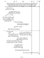
- Fig.3 is a flowchart of another embodiment of a method for session routing in the present invention.
- Step 301 when an MN is in a second network, the MN performs a session with a CN2 through a pAR, the MN stores a corresponding relationship between an address of the pAR and IP address information allocated by the pAR to the MN, and the pAR establishes a binding list for the MN.
- the following table 1 is a corresponding relationship list maintained in the MN, wherein it is assumed that the address of the pAR is expressed as pAR-address, and the IP address information allocated by the pAR to the MN is expressed as IPp: Table 1 pAR-address IPp
- the following table 2 is the binding list established by the pAR for the MN, wherein an identifier of the MN is expressed as MN id, and the IP address information allocated by the pAR to the MN is expressed as IPp: Table 2 MN id IPp
- Step 302 after entering a first network in which an nAR is located, the MN is attached to the nAR, and the nAR establishes a binding list for the MN.
- Step 303 the nAR sends an RA (Router Advertisement, router advertisement) message to the MN, wherein the RA message at least contains IP address information allocated by the nAR to the MN and an address of the nAR.
- RA Router Advertisement, router advertisement
- the global address of the nAR is carried by a prefix information option (prefix information option) in the RA message.
- the nAR stores a corresponding relationship between the identifier of the MN and the IP address information allocated to the MN in the binding list established for the MN.
- the following table 3 is the binding list established by the nAR for the MN, wherein it is assumed that the identifier of the MN is expressed as MN id, and the IP address information allocated by the nAR to the MN is expressed as IPn: Table 3 MN id IPn
- Step 304 the MN obtains the address of the nAR from the RA message, updates the maintained corresponding relationship list and configures an IP address in the first network according to the IP address information in the RA message.
- the corresponding relationship list updated by the MN is as shown in the following table 4, wherein the address of the nAR is expressed as nAR-address, and the IP address information allocated by the nAR to the MN is expressed as IPn: Table 4 pAR-address IPp nAR-address IPn
- Step 305 the MN sends an RS (Router solicitation, router solicitation) message to the nAR, wherein the RS message contains the corresponding relationship between the address of the pAR and the IP address information allocated by the pAR to the MN.
- RS Radio solicitation, router solicitation
- the MN may obtain a corresponding relationship of a session maintained by the MN in other networks excluding the first network by searching the table 4, in the embodiment, i.e., obtaining the corresponding relationship between the pAR-address and the IPp.
- Step 306 after receiving the RS message, the nAR establishes one end of a tunnel with the pAR by sending a PBU message to the pAR, wherein the PBU message at least contains the address of the nAR and the identifier of the MN.
- the nAR may send the PBU (Proxy Binding Update, proxy binding update) message to the pAR according to the address of the pAR in the RS message, wherein the address of the nAR contained in the RS message may be used for enabling the pAR to finish establishing the tunnel with the nAR according to the address of the nAR, and the identifier of the MN is used for enabling the pAR to find out the binding relationship list established for the MN.
- PBU Proxy Binding Update, proxy binding update
- Step 307 the pAR updates the binding list established for the MN and adds the address of the nAR as a delivering address of the MN.
- the address of the nAR and the identifier of the MN therein are obtained, a corresponding relationship table entry maintained for the MN is found out according to the identifier of the MN, and the address of the nAR is added in the table entry as the delivering address of the MN.
- the following table 5 is the binding list updated by the pAR and established for the MN, and compared with the table 2, the delivering address nAR-address is added.
- Step 308 the pAR replies a PBA (Proxy Binding Acknowledgement, proxy binding acknowledgement) message to the nAR according to the address of the nAR in the PBU message, to establish the other end of the tunnel with the nAR.
- PBA Proxy Binding Acknowledgement, proxy binding acknowledgement
- the pAR may also delete corresponding relationships of other IP addresses of the MN and AR addresses corresponding to these IP addresses, and remove tunnels established with these ARs.
- Step 309 after receiving the PBA message, the nAR updates the binding list established for the MN, and adds the address of the pAR and the IP address information allocated by the pAR to the MN in the binding list.
- the following table 6 is the binding list established for the MN and updated by the nAR according to the address of the pAR and the IP address information allocated by the pAR to the MN obtained in step 305, and compared with the table 3, the address of the pAR and the address information allocated by the pAR to the MN are added.
- Table 6 MN id IPn pAR-address IPp
- Step 310 the MN sends a data packet to the nAR.
- these data packets may be data packets sent to the CN1 in the first network, or data packets sent to the CN2 in the second network.
- Step 311 the nAR detects a source IP address of the data packet, if the source IP address is allocated by the nAR, a step 312 is executed; and if not, a step 313 is executed.
- Step 312 the nAR directly routes the data packet to the CN1 in the first network, and terminates the flow.
- the nAR When the nAR detects the source IP address of the data packet is allocated by the nAR, it indicates that the current session is a session initiated in the first network. In the embodiment, if a terminal corresponding to the target IP address of the data packet is the CN1 in the first network, the nAR directly routes the data packet to the CN1 in the first network according to the target IP address of the data packet. It should be noted that the terminal corresponding to the target IP address of the data packet may also be a CN in other networks excluding the first network, for example, a CN3 in a third network, at this time, the nAR routes the data packet to an AR in the third network, and the AR in the third network routes the data packet to the CN3.
- Step 313 the nAR finds out the address of the pAR corresponding to the source IP address in the binding list.
- the nAR searches the binding list as shown in table 6 according to the source IP address, and if it can be found out that the source IP address is allocated by the pAR, it indicates that a terminal having a session with the MN is a terminal in the second network.
- Step 314 the nAR performs tunnel encapsulation on the data packet, and forwards the data packet to the pAR according to the address of the pAR.
- the address of the nAR is used as an outer layer source IP address of the data packet, and the found out address of the pAR is used as an outer layer target IP address of the data packet.
- the encapsulated data packet is transmitted to the pAR according to the outer layer target IP address through the established tunnel.
- Step 315 after receiving the data packet, the pAR decapsulates the data packet.
- the pAR decapsulates to remove the outer layer IP address of the data packet, wherein a source IP address of the decapsulated data packet is IPp, a target IP address is an IP address of the CN2 in the second network, and the data packet may be routed by the pAR in the second network subsequently.
- Step 316 the pAR routes the data packet to the CN2 in the second network according to the target IP address of the decapsulated data packet.
- a source IP address of the data packet is the IP address of the CN2
- a target IP address is IPp
- the data packet may be firstly routed to the pAR, then the pAR searches the binding list as shown in table 5 according to the IPp to obtain a corresponding delivering address nAR-address, and performs tunnel encapsulation on the data packet, an outer layer target IP address is nAR-address, an outer layer source IP address is pAR-address, after the encapsulated data packet is routed to the nAR according to the outer layer target IP address, the nAR decapsulates the data packet and routes the data packet to the MN by searching the table 6 according to the target IP address IPp of the data packet.
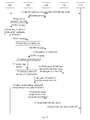
- Fig.4 is a flowchart of another embodiment of a method for session routing in the present invention.
- Step 401 when an MN is in a second network, the MN performs a session with a CN2 through a pAR, the MN stores a corresponding relationship between an address of the pAR and IP address information allocated by the pAR to the MN in a configuration file, and the pAR establishes a binding list for the MN.
- a corresponding relationship list stored by the MN in the configuration file is consistent with the table 1 in the foregoing embodiment, and the binding list established by the pAR for the MN is consistent with the table 2 in the foregoing embodiment.
- Step 402 after entering a first network in which an nAR is located, the MN is attached to the nAR, and the nAR establishes a binding list for the MN.
- Step 403 the nAR obtains and stores the configuration file of the MN, wherein the configuration file contains the corresponding relationship between the address of the pAR and the IP address information allocated by the pAR to the MN.
- Step 404 the nAR sends an RA message to the MN, wherein the RA message at least contains IP address information allocated by the nAR to the MN and an address of the nAR.
- the global address of the nAR is carried by a prefix information option (prefix information option) in the RA message.
- the nAR stores a corresponding relationship between the identifier of the MN and the IP address information allocated to the MN in the binding list established for the MN.
- the binding list established by the nAR for the MN is consistent with the table 3 in the foregoing embodiment.
- Step 405 the MN obtains the address of the nAR from the RA message, updates the obtained configuration file and configures an IP address in the first network according to the IP address information in the RA message.
- the configuration file updated by the MN is consistent with the table 4 in the foregoing embodiment.
- Step 406 the nAR establishes one end of a tunnel with the pAR by sending a PBU message to the pAR, wherein the PBU message at least contains the address of the nAR and the identifier of the MN.
- step 406 may be executed with the foregoing step 404 simultaneously.
- Step 407 the pAR updates the binding list established for the MN and adds the address of the nAR as a delivering address of the MN.
- the address of the nAR and the identifier of the MN therein are obtained, a corresponding relationship table entry maintained for the MN is found out according to the identifier of the MN, and the address of the nAR is added in the table entry as the delivering address of the MN.
- the binding list updated by the pAR is consistent with the table 5 in the foregoing embodiment.
- Step 408 the pAR replies a PBA message to the nAR according to the address of the nAR in the PBU message, to establish the other end of the tunnel with the nAR.
- the pAR may delete corresponding relationships of other IP addresses of the MN and AR addresses corresponding to these IP addresses, and remove the tunnels established with these ARs.
- Step 409 after receiving the PBA message, the nAR updates the binding list established for the MN, and adds the address of the pAR and the IP address information allocated by the pAR to the MN in the binding list.
- the nAR updates the binding list established for the MN according to the address of the pAR and the IP address information allocated by the pAR to the MN stored in the configuration file in step 403, and the binding list is consistent with the table 6 in the foregoing embodiment.
- Step 410 the MN sends a data packet to the nAR.
- these data packets may be data packets sent to the CN1 in the first network, or data packets sent to the CN2 in the second network.
- Step 411 the nAR detects a source IP address of the data packet, if the source IP address is allocated by the nAR, a step 412 is executed; and if not, a step 413 is executed.
- Step 412 the nAR directly routes the data packet to the CN1 in the first network, and terminates the flow.
- the nAR When the nAR detects that the source IP address of the data packet is allocated by the nAR, it indicates that the current session is a session initiated in the first network. In the embodiment, if a terminal corresponding to the target IP address of the data packet is the CN1 in the first network, the nAR directly routes the data packet to the CN1 in the first network according to the target IP address of the data packet. It should be noted that the terminal corresponding to the target IP address of the data packet may also be a CN in other networks excluding the first network, for example, a CN3 in a third network, at this time, the nAR routes the data packet to an AR in the third network, and the AR in the third network routes the data packet to the CN3.
- Step 413 the nAR finds out the address of the pAR corresponding to the source IP address in the binding list.
- the nAR searches the binding list as shown in table 6 according to the source IP address, and if it can be found out that the source IP address is allocated by the pAR, it indicates that the session is a session initiated in the second network.
- Step 414 the nAR performs tunnel encapsulation on the data packet, and forwards the data packet to the pAR according to the address of the pAR.
- the address of the nAR is used as an outer layer source IP address of the data packet, and the found out address of the pAR is used as an outer layer target IP address of the data packet.
- the encapsulated data packet is transmitted to the pAR according to the outer layer target IP address through the established tunnel.
- Step 415 after receiving the data packet, the pAR decapsulates the data packet.
- the pAR decapsulates to remove the outer layer IP address of the data packet, wherein a source IP address of the decapsulated data packet is IPp, a target IP address is an IP address of the CN2 in the second network, and the data packet may be routed by the pAR in the second network subsequently.
- Step 416 the pAR routes the data packet to the CN2 in the second network according to the target IP address of the decapsulated data packet.
- a source IP address of the data packet is the IP address of the CN2
- a target IP address is IPp
- the data packet may be firstly routed to the pAR, then the pAR searches the binding list as shown in table 5 according to the IPp to obtain a corresponding delivering address nAR-address, and performs tunnel encapsulation on the data packet, an outer layer target IP address is nAR-address, an outer layer source IP address is pAR-address, after the encapsulated data packet is routed to the nAR according to the outer layer target IP address, the nAR decapsulates the data packet and routes the data packet to the MN by searching the table 6 according to the target IP address IPp of the data packet.
- Fig.5 is a flowchart of another embodiment of a method for session routing in the present invention.
- Step 501 when an MN is in a second network, the MN performs a session with a CN2 through a pAR, the MN stores IP address information allocated by the pAR to the MN, and the pAR establishes a binding list for the MN.
- the binding list established by the pAR for the MN is consistent with the table 2 in the foregoing embodiment.
- Step 502 an nAR and the pAR interact corresponding relationships between addresses and IP address domains of themselves through a routing message, and store these corresponding relationships through matched lists.
- the IP address domain refers to a set of all IP address information capable of being allocated by each AR to the MN, and IP address information allocated to one MN at each time is selected from the IP address domain.
- the pAR may transmit the corresponding relationship between the address of the pAR and the IP address domain capable of being allocated by the pAR to the MN through the routing message.
- Step 503 after entering a first network in which the nAR is located, the MN is attached to the nAR, and the nAR establishes a binding list for the MN.
- the binding list established by the nAR for the MN is consistent with the table 3 in the foregoing embodiment.
- Step 504 the nAR sends an RA message to the MN, wherein the RA message at least contains IP address information allocated by the nAR to the MN.
- Step 505 the MN obtains the IP address information from the RA message, and configures an IP address in the first network.
- Step 506 the MN sends an RS message to the nAR, wherein the RS message contains IP address information needing to maintain a session, and the IP address information is allocated by the pAR.
- step may be executed with step 505 simultaneously.
- Step 507 the nAR searches the matched list to obtain the address of the pAR corresponding to the IP address information in the RS message.
- the nAR After receiving the RS message, the nAR obtains the IP address information needing to maintain the session from the RS message, searches the matched list to obtain the IP address domain to which the IP address information belongs, and then obtains the address of the pAR corresponding to the IP address domain.
- Step 508 the nAR establishes one end of a tunnel with the pAR by sending a PBU message to the pAR, wherein the PBU message at least contains the address of the nAR and the identifier of the MN.
- Step 509 the pAR updates the binding list established for the MN and adds the address of the nAR as a delivering address of the MN.
- the address of the nAR and the identifier of the MN therein are obtained, a corresponding relationship table entry maintained for the MN is found out according to the identifier of the MN, and the address of the nAR is added in the table entry as the delivering address of the MN.
- the binding list updated by the pAR is consistent with the table 5 in the foregoing embodiment.
- Step 510 the pAR replies a PBA message to the nAR according to the address of the nAR in the PBU message, to establish the other end of the tunnel with the nAR.
- Step 511 after receiving the PBA message, the nAR updates the binding list established for the MN, and adds the address of the pAR and the IP address information allocated by the pAR to the MN in the binding list.
- the binding list established for the MN and updated by the nAR is consistent with the table 6 in the foregoing embodiment.
- Step 512 the MN sends a data packet to the nAR.
- these data packets may be data packets sent to the CN1 in the first network, or data packets sent to the CN2 in the second network.
- Step 513 the nAR detects a source IP address of the data packet, if the source IP address is allocated by the nAR, a step 514 is executed; and if not, a step 515 is executed.
- Step 514 the nAR directly routes the data packet to the CN1 in the first network, and terminates the flow.
- the nAR detects that the source IP address of the data packet is allocated by the nAR, it indicates that the current session is a session initiated in the first network.
- a terminal corresponding to the target IP address of the data packet is the CN1 in the first network
- the nAR directly routes the data packet to the CN1 in the first network according to the target IP address of the data packet.
- the terminal corresponding to the target IP address of the data packet may also be a CN in other networks excluding the first network, for example, a CN3 in a third network, at this time, the nAR routes the data packet to an AR in the third network, and the AR in the third network routes the data packet to the CN3.
- Step 515 the nAR finds out the address of the pAR corresponding to the source IP address in the binding list.
- the nAR searches the binding list as shown in table 6 according to the source IP address, and if it can be found out that the source IP address is allocated by the pAR, it indicates that the session is a session initiated in the second network.
- Step 516 the nAR performs tunnel encapsulation on the data packet, and forwards the data packet to the pAR according to the address of the pAR.
- the address of the nAR is used as an outer layer source IP address of the data packet, and the found out address of the pAR is used as an outer layer target IP address of the data packet.
- the encapsulated data packet is transmitted to the pAR according to the outer layer target IP address through the established tunnel.
- Step 517 after receiving the data packet, the pAR decapsulates the data packet.
- the pAR decapsulates to remove the outer layer IP address of the data packet, wherein a source IP address of the decapsulated data packet is IPp, a target IP address is an IP address of the CN2 in the second network, and the data packet may be routed by the pAR in the second network subsequently.
- Step 518 the pAR routes the data packet to the CN2 in the second network according to the target IP address of the decapsulated data packet.
- a source IP address of the data packet is the IP address of the CN2
- a target IP address is IPp
- the data packet may be firstly routed to the pAR, then the pAR searches the binding list as shown in table 5 according to the IPp to obtain a corresponding delivering address nAR-address, and performs tunnel encapsulation on the data packet, an outer layer target IP address is nAR-address, an outer layer source IP address is pAR-address, after the encapsulated data packet is routed to the nAR according to the outer layer target IP address, the nAR decapsulates the data packet and routes the data packet to the MN by searching the table 6 according to the target IP address IPp of the data packet.
- Fig.6 is a flowchart of another embodiment of a method for session routing in the present invention.
- Step 601 when an MN is in a second network, the MN performs a session with a CN2 through a pAR, the MN stores IP address information allocated by the pAR to the MN, and the pAR establishes a binding list for the MN.
- the binding list established by the pAR for the MN is consistent with the table 2 in the foregoing embodiment.
- Step 602 an nAR and the pAR interact corresponding relationships between addresses and IP address domains of themselves through a routing message, and store these corresponding relationships through matched lists.
- the IP address domain refers to a set of all IP address information capable of being allocated by each AR to the MN, and IP address information allocated to one MN at each time is selected from the IP address domain.
- the pAR may transmit the corresponding relationship between the address of the pAR and the IP address domain capable of being allocated by the pAR to the MN through the routing message.
- Step 603 after entering a first network in which the nAR is located, the MN is attached to the nAR, and the nAR establishes a binding list for the MN.
- Step 604 the nAR sends an RA message to the MN, wherein the RA message at least contains IP address information allocated by the nAR to the MN.
- Step 605 the MN obtains the IP address information from the RA message, and configures an IP address in the first network.
- Step 606 the MN sends a data packet to the nAR.
- these data packets may be data packets sent to the CN1 in the first network, or data packets sent to the CN2 in the second network.
- Step 607 the nAR detects a source IP address of the data packet, if the source IP address is allocated by the nAR, a step 608 is executed; and if not, a step 609 is executed.
- Step 608 the nAR directly routes the data packet to the CN1 in the first network, and terminates the flow.
- the nAR When the nAR detects that the source IP address of the data packet is allocated by the nAR, it indicates that the current session is a session initiated in the first network. In the embodiment, if a terminal corresponding to the target IP address of the data packet is the CN1 in the first network, then the nAR directly routes the data packet to the CN1 in the first network according to the target IP address of the data packet. It should be noted that the terminal corresponding to the target IP address of the data packet may also be a CN in other networks excluding the first network, for example, a CN3 in a third network, at this time, the nAR routes the data packet to an AR in the third network, and the AR in the third network routes the data packet to the CN3.
- Step 609 the nAR searches the matched list to obtain the address of the pAR corresponding to the IP address information of the source IP address.
- the nAR searches the matched list to obtain the IP address domain to which the IP address information belongs, and then obtains the address of the pAR corresponding to the IP address domain.
- Step 610 the nAR establishes one end of a tunnel with the pAR by sending a PBU message to the pAR, wherein the PBU message at least contains the address of the nAR and the identifier of the MN.
- Step 611 the pAR updates the binding list established for the MN and adds the address of the nAR as a delivering address of the MN.
- the address of the nAR and the identifier of the MN therein are obtained, a corresponding relationship table entry maintained for the MN is found out according to the identifier of the MN, and the address of the nAR is added in the table entry as the delivering address of the MN.
- the binding list updated by the pAR is consistent with the table 5 in the foregoing embodiment.
- Step 612 the pAR replies a PBA message to the nAR according to the address of the nAR in the PBU message, to establish the other end of the tunnel with the nAR.
- Step 613 after receiving the PBA message, the nAR updates the binding list established for the MN, and adds the address of the pAR and the IP address information allocated to the MN in the binding list.
- the binding list established for the MN and updated by the nAR is consistent with the table 6 in the foregoing embodiment.
- Step 614 the nAR performs tunnel encapsulation on the data packet, and forwards the data packet to the pAR according to the address of the pAR.
- the address of the nAR is used as an outer layer source IP address of the data packet, and the found out address of the pAR is used as an outer layer target IP address of the data packet.
- the encapsulated data packet is transmitted to the pAR according to the outer layer target IP address through the established tunnel.
- Step 615 after receiving the data packet, the pAR decapsulates the data packet.
- the pAR decapsulates to remove the outer layer IP address of the data packet, wherein a source IP address of the decapsulated data packet is IPp, a target IP address is an IP address of the CN2 in the second network, and the data packet may be routed by the pAR in the second network subsequently.
- Step 616 the pAR routes the data packet to the CN2 in the second network according to the target IP address of the decapsulated data packet.
- a source IP address of the data packet is the IP address of the CN2
- a target IP address is IPp
- the data packet may be firstly routed to the pAR, then the pAR searches the binding list as shown in table 5 according to the IPp to obtain a corresponding delivering address nAR-address, and performs tunnel encapsulation on the data packet, an outer layer target IP address is nAR-address, an outer layer source IP address is pAR-address, after the encapsulated data packet is routed to the nAR according to the outer layer target IP address, the nAR decapsulates the data packet and routes the data packet to the MN by searching the table 6 according to the target IP address IPp of the data packet.
- the present invention further provides embodiments of a device and a system for session routing.
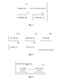
- Fig.7 is a block diagram of an embodiment of a device for session routing in the present invention.
- the device for session routing serves as a first routing device in a first network and includes: an obtaining unit 710, an establishing unit 720 and a routing unit 730:
- Fig.8 is a block diagram of another embodiment of a device for session routing in the present invention.
- the device for session routing serves as a first routing device in a first network and includes: an obtaining unit 810, an establishing unit 820, a routing unit 830, a sending unit 840, a detecting unit 850 and a routing unit 860:
- Fig.9 is a block diagram of an embodiment of a system for session routing in the present invention.
- the system for session routing includes: a first routing device 910 and a second routing device 920.
- the first routing device 910 is configured to, when a first terminal enters a first network in which the first routing device 910 is located, obtain an address of the second routing device 920 in a second network, establish a tunnel with the second routing device 920 according to the address of the second routing device 920, and maintain a session between the first terminal and the second routing device 920 through the tunnel; and the second routing device 920 is configured to route the session to a second terminal in the second network.
- the first routing device 910 is further configured to, after the first terminal enters the first network in which the first routing device 910 is located, send a router advertisement message to the first terminal, wherein the router advertisement message contains an address of the first routing device and IP address information allocated by the first routing device to the first terminal, so that the first terminal stores a corresponding relationship between the address of the first routing device and the IP address information allocated by the first routing device to the first terminal, and configures an IP address of the first terminal in the first network according to the IP address information; and after receiving a data packet sent by the first terminal according to the address of the first routing device, detect that address information of a source IP address of the data packet is allocated by the first routing device, and route the data packet to a third terminal in the first network.
- the first routing device 910 is further configured to, after the first terminal enters the first network in which the first routing device 910 is located, send a router advertisement message to the first terminal, wherein the router advertisement message contains an address of the first routing device and IP address information allocated by the first routing device to the first terminal, so that the first terminal stores a corresponding relationship between the address of the first routing device and the IP address information allocated by the first routing device to the first terminal, and configure an IP address of the first terminal in the first network according to the IP address information; and after receiving a data packet sent by the first terminal, detect that a source IP address of the data packet is the IP address of the first terminal in the first network, and route the data packet to the third terminal corresponding to a target IP address according to the target IP address of the data packet.
- the routing device to which the terminal is attached is generally called as the first routing device, and the routing device still needing to maintain the session with the terminal in other networks is called as the second routing device, namely, the number of the second routing device may be more than one, the process of performing the session between each second routing device and the first routing device is consistent, therefore, the second routing device in the embodiments of the present invention is used for uniform description, and the second routing device should not be construed as limitation of merely one second routing device in the system.
- the first routing device obtains the address of the second routing device in the second network, the first routing device establishes the tunnel with the second routing device according to the address of the second routing device, and maintains the session between the first terminal and the second routing device through the tunnel, so that the second routing device routes the session to the second terminal in the second network.
- the terminal may no longer belong to a fixed routing device in the home network, when the terminal enters a network, session routing between the terminal and a routing device in other networks is achieved by a routing device to which the terminal is attached in the network, and since the routing device to which the terminal belongs varies with the network in which the terminal is located, the communication traffic of the terminal may not be concentrated on one routing device for forwarding, thus reducing the processing load of a single routing device.
- the included units are only divided according to functional logic, but are not limited to the above-mentioned division, as long as corresponding functions can be achieved; and in addition, the specific names of the functional units are merely for convenience of mutual distinction, rather than limiting the protection scope of the present invention.
Landscapes
- Engineering & Computer Science (AREA)
- Computer Networks & Wireless Communication (AREA)
- Signal Processing (AREA)
- Databases & Information Systems (AREA)
- Data Exchanges In Wide-Area Networks (AREA)
Applications Claiming Priority (1)
| Application Number | Priority Date | Filing Date | Title |
|---|---|---|---|
| PCT/CN2012/077606 WO2014000175A1 (zh) | 2012-06-27 | 2012-06-27 | 会话路由方法、设备及系统 |
Publications (2)
| Publication Number | Publication Date |
|---|---|
| EP2869507A1 true EP2869507A1 (de) | 2015-05-06 |
| EP2869507A4 EP2869507A4 (de) | 2015-06-24 |
Family
ID=49782042
Family Applications (1)
| Application Number | Title | Priority Date | Filing Date |
|---|---|---|---|
| EP12879898.0A Withdrawn EP2869507A4 (de) | 2012-06-27 | 2012-06-27 | Verfahren, vorrichtung und system zum routen von sitzungen |
Country Status (4)
| Country | Link |
|---|---|
| US (1) | US20150110115A1 (de) |
| EP (1) | EP2869507A4 (de) |
| CN (1) | CN103621021A (de) |
| WO (1) | WO2014000175A1 (de) |
Families Citing this family (3)
| Publication number | Priority date | Publication date | Assignee | Title |
|---|---|---|---|---|
| CN117221045A (zh) * | 2020-08-28 | 2023-12-12 | 柏思科技有限公司 | 用于传输基于会话的包的方法和系统 |
| US11778467B2 (en) * | 2021-10-28 | 2023-10-03 | Hewlett Packard Enterprise Development Lp | Precaching precursor keys within a roaming domain of client devices |
| CN117014897A (zh) * | 2022-04-27 | 2023-11-07 | 中国移动通信集团浙江有限公司 | 同基站下专网终端互联方法、装置、设备及存储介质 |
Family Cites Families (9)
| Publication number | Priority date | Publication date | Assignee | Title |
|---|---|---|---|---|
| US7886075B2 (en) * | 2003-05-16 | 2011-02-08 | Cisco Technology, Inc. | Arrangement for retrieving routing information for establishing a bidirectional tunnel between a mobile router and a correspondent router |
| CN100389581C (zh) * | 2004-09-29 | 2008-05-21 | 华为技术有限公司 | 一种保障端到端业务质量的方法 |
| KR101117283B1 (ko) * | 2004-10-11 | 2012-03-21 | 삼성전자주식회사 | 무선랜망과 이동통신 시스템에 접속 가능한 듀얼모드단말의 액티브 핸드오프 시스템 및 방법 |
| CN101080913A (zh) * | 2004-12-14 | 2007-11-28 | 松下电器产业株式会社 | 通信路由优化方法、相应的设备和系统 |
| US8155085B2 (en) * | 2006-07-28 | 2012-04-10 | Panasonic Corporation | Mobile communication method and access router |
| EP2009866A1 (de) * | 2007-06-26 | 2008-12-31 | France Télécom | Telekommunikationssystem und Verfahren für das Kommunizieren der Anforderung einer Internet-Protokolladresse zum Visited Serving Gateway |
| KR100885748B1 (ko) * | 2007-08-07 | 2009-02-26 | 포스데이타 주식회사 | 무선 통신 네트워크에서 MIPv6 서비스를 지원하는 방법및 장치 |
| EP2253153A1 (de) * | 2008-03-03 | 2010-11-24 | Panasonic Corporation | Informationsaustausch zwischen gateways für routenoptimierung mit netzbasierten mobilitätsmanagements |
| WO2010151687A2 (en) * | 2009-06-24 | 2010-12-29 | Zte U.S.A., Inc. | Method and system for protocol configuration in wireless communication systems |
-
2012
- 2012-06-27 CN CN201280000931.0A patent/CN103621021A/zh active Pending
- 2012-06-27 EP EP12879898.0A patent/EP2869507A4/de not_active Withdrawn
- 2012-06-27 WO PCT/CN2012/077606 patent/WO2014000175A1/zh not_active Ceased
-
2014
- 2014-12-23 US US14/581,204 patent/US20150110115A1/en not_active Abandoned
Also Published As
| Publication number | Publication date |
|---|---|
| CN103621021A (zh) | 2014-03-05 |
| WO2014000175A1 (zh) | 2014-01-03 |
| US20150110115A1 (en) | 2015-04-23 |
| EP2869507A4 (de) | 2015-06-24 |
Similar Documents
| Publication | Publication Date | Title |
|---|---|---|
| CN102907072B (zh) | 利用NAT64启用IPv6移动性 | |
| JP5186603B2 (ja) | マルチホーム移動ノードによるホーム・ネットワーク及びフォーリン・ネットワークの同時使用を可能にするための方法 | |
| US9167482B2 (en) | Method and system for realizing network switching | |
| KR100879985B1 (ko) | 비손실 모바일 ip 패킷 전달 방법 및 그 시스템 | |
| KR101439270B1 (ko) | 다중 케어 오브 어드레싱을 갖는 이동 노드의 터널 통신의 연속성 지원 | |
| CN101511117B (zh) | 一种二层跨网段通信的方法、系统和设备 | |
| KR101031979B1 (ko) | 통신 시스템 | |
| KR20150074220A (ko) | 고속 핸드오프 전이 동안 이동성 액세스 게이트웨이 간의 터널링을 위한 시스템 및 프로토콜들 | |
| US8824353B2 (en) | Mobility route optimization in a network having distributed local mobility anchors | |
| EP2536071B1 (de) | Verfahren, system, forward-mapping-server und zugangsrouter für mobile kommunikationssteuerung | |
| WO2007131404A1 (fr) | Méthode et dispositif de transfert rapide | |
| US8762500B2 (en) | Network mobility for multi-level networks | |
| JP2011501916A (ja) | マルチホーミング・プロトコルのためのサポート | |
| EP2869507A1 (de) | Verfahren, vorrichtung und system zum routen von sitzungen | |
| US8675555B2 (en) | Proxy mobile internet protocol version six multihoming support for flow mobility | |
| CN102769676B (zh) | Ip网络移动管理方法、装置和系统 | |
| Condeixa et al. | Centralized, distributed or replicated IP mobility? | |
| WO2007112806A1 (de) | Efficient handover of a mobile node within a network with multiple anchor | |
| US20100175109A1 (en) | Route optimisation for proxy mobile ip | |
| CN105191417B (zh) | 路由方法及路由装置 | |
| CN101204098B (zh) | 用于提供分布式虚拟移动代理的系统和方法 | |
| CN101426240B (zh) | 控制移动节点在异构接入网之间切换的方法及装置 | |
| US20080151855A1 (en) | Method for optimizing the communication between mobile nodes | |
| US10356598B2 (en) | Mobility management method, apparatus, and system | |
| Seite et al. | Network Working Group H. Chan (Ed.) Internet-Draft Huawei Technologies (more Intended status: Informational co-authors on P. 17) Expires: December 7, 2013 D. Liu China Mobile |
Legal Events
| Date | Code | Title | Description |
|---|---|---|---|
| PUAI | Public reference made under article 153(3) epc to a published international application that has entered the european phase |
Free format text: ORIGINAL CODE: 0009012 |
|
| 17P | Request for examination filed |
Effective date: 20141230 |
|
| AK | Designated contracting states |
Kind code of ref document: A1 Designated state(s): AL AT BE BG CH CY CZ DE DK EE ES FI FR GB GR HR HU IE IS IT LI LT LU LV MC MK MT NL NO PL PT RO RS SE SI SK SM TR |
|
| AX | Request for extension of the european patent |
Extension state: BA ME |
|
| RA4 | Supplementary search report drawn up and despatched (corrected) |
Effective date: 20150527 |
|
| RIC1 | Information provided on ipc code assigned before grant |
Ipc: H04W 36/00 20090101ALI20150520BHEP Ipc: H04L 29/06 20060101ALI20150520BHEP Ipc: H04W 40/36 20090101ALI20150520BHEP Ipc: H04L 12/721 20130101AFI20150520BHEP |
|
| DAX | Request for extension of the european patent (deleted) | ||
| STAA | Information on the status of an ep patent application or granted ep patent |
Free format text: STATUS: THE APPLICATION HAS BEEN WITHDRAWN |
|
| 18W | Application withdrawn |
Effective date: 20161223 |