EP2869975B1 - Elektrowerkzeug - Google Patents
Elektrowerkzeug Download PDFInfo
- Publication number
- EP2869975B1 EP2869975B1 EP14715059.3A EP14715059A EP2869975B1 EP 2869975 B1 EP2869975 B1 EP 2869975B1 EP 14715059 A EP14715059 A EP 14715059A EP 2869975 B1 EP2869975 B1 EP 2869975B1
- Authority
- EP
- European Patent Office
- Prior art keywords
- fence
- cutting
- guide means
- base
- blade
- Prior art date
- Legal status (The legal status is an assumption and is not a legal conclusion. Google has not performed a legal analysis and makes no representation as to the accuracy of the status listed.)
- Active
Links
Images






Classifications
-
- B—PERFORMING OPERATIONS; TRANSPORTING
- B27—WORKING OR PRESERVING WOOD OR SIMILAR MATERIAL; NAILING OR STAPLING MACHINES IN GENERAL
- B27B—SAWS FOR WOOD OR SIMILAR MATERIAL; COMPONENTS OR ACCESSORIES THEREFOR
- B27B27/00—Guide fences or stops for timber in saw mills or sawing machines; Measuring equipment thereon
- B27B27/08—Guide fences or stops for timber in saw mills or sawing machines; Measuring equipment thereon arranged adjustably, not limited to only one of the groups B27B27/02 - B27B27/06
-
- B—PERFORMING OPERATIONS; TRANSPORTING
- B27—WORKING OR PRESERVING WOOD OR SIMILAR MATERIAL; NAILING OR STAPLING MACHINES IN GENERAL
- B27B—SAWS FOR WOOD OR SIMILAR MATERIAL; COMPONENTS OR ACCESSORIES THEREFOR
- B27B27/00—Guide fences or stops for timber in saw mills or sawing machines; Measuring equipment thereon
- B27B27/02—Guide fences or stops for timber in saw mills or sawing machines; Measuring equipment thereon arranged laterally and parallel with respect to the plane of the saw blade
-
- B—PERFORMING OPERATIONS; TRANSPORTING
- B27—WORKING OR PRESERVING WOOD OR SIMILAR MATERIAL; NAILING OR STAPLING MACHINES IN GENERAL
- B27B—SAWS FOR WOOD OR SIMILAR MATERIAL; COMPONENTS OR ACCESSORIES THEREFOR
- B27B27/00—Guide fences or stops for timber in saw mills or sawing machines; Measuring equipment thereon
- B27B27/06—Guide fences or stops for timber in saw mills or sawing machines; Measuring equipment thereon arranged angularly with respect to the plane of the saw blade, e.g. for mitring
-
- B—PERFORMING OPERATIONS; TRANSPORTING
- B27—WORKING OR PRESERVING WOOD OR SIMILAR MATERIAL; NAILING OR STAPLING MACHINES IN GENERAL
- B27B—SAWS FOR WOOD OR SIMILAR MATERIAL; COMPONENTS OR ACCESSORIES THEREFOR
- B27B5/00—Sawing machines working with circular or cylindrical saw blades; Components or equipment therefor
- B27B5/16—Saw benches
- B27B5/18—Saw benches with feedable circular saw blade, e.g. arranged on a carriage
- B27B5/181—Saw benches with feedable circular saw blade, e.g. arranged on a carriage the saw blade being arranged underneath a work-table
- B27B5/184—Saw benches with feedable circular saw blade, e.g. arranged on a carriage the saw blade being arranged underneath a work-table the saw blade performing a rectilinear movement only
-
- B—PERFORMING OPERATIONS; TRANSPORTING
- B27—WORKING OR PRESERVING WOOD OR SIMILAR MATERIAL; NAILING OR STAPLING MACHINES IN GENERAL
- B27B—SAWS FOR WOOD OR SIMILAR MATERIAL; COMPONENTS OR ACCESSORIES THEREFOR
- B27B5/00—Sawing machines working with circular or cylindrical saw blades; Components or equipment therefor
- B27B5/16—Saw benches
- B27B5/18—Saw benches with feedable circular saw blade, e.g. arranged on a carriage
- B27B5/187—Saw benches with feedable circular saw blade, e.g. arranged on a carriage the saw blade being fitted on a movable carriage
Definitions
- the invention to which this application relates is to apparatus which can be used to perform cutting actions on one or more work pieces such as, but not exclusively, work pieces in the form of sheet material such as, for example, wooden and/or laminate flooring, as per the preamble of claim 1.
- work pieces such as, but not exclusively, work pieces in the form of sheet material such as, for example, wooden and/or laminate flooring, as per the preamble of claim 1.
- An example of such an apparatus is disclosed by US 4 995 288 A .
- a further problem is that the manual cutting of the laminate sheet material can be tiring for the person and therefore on occasion, they may attempt to perform the cutting action using other power tools which may not be suitable for the particular purpose and can therefore be dangerous to use and therefore may not achieve a particularly attractive finish.
- US Patent No. 8,186,257 B2 provides a laminate-flooring saw system that can be used to create different cuts.
- An aim of the present invention is to provide apparatus of a form which can be used to perform a cutting action on a work piece, more typically a relatively thin elongate workpiece such as laminate flooring, flooring panels or the like and to allow the cutting action to be performed on site and in an accurate manner and providing an increased number of cutting angles that a work piece may be cut along.
- a further aim of the present invention is also to provide such an apparatus with a means to ensure accurate cutting along the cutting line is achieved.
- a yet further aim of the present invention is to provide a cutting apparatus that will maximise the size of workpiece which can be cut using the apparatus.
- the invention provides a powered cutting apparatus, said apparatus comprising the features of claim 1.
- the present invention therefore has the advantage that the fence provided on the power cutting apparatus when positioned with the second guide means can be selectively positioned so as to be adjustable across a wide range of angles, allowing a work piece to be cut with much greater accuracy.
- the apparatus of the present invention provides a user with the facility to make suitable cutting styles such as any of cross cuts, rip cuts, and/or a wide variety of mitre cuts on a work piece.
- the positioning of the fence with said first and/or second guide means can be selected and locked using one or more locking means.
- said locking means comprise one or more threaded bolts or screws and/or a cam assembly.
- said first guide means are provided in the form of at least two spaced apart slots or rails on the base of the apparatus.
- the longitudinal axes of the slots are substantially perpendicular to the longitudinal axis of the slides.
- said first guide means are located in the apparatus such that the cutting plane of the rotatable blade is located between the first guide means and the slides.
- said fence when the fence is located on the first guide means, said fence is located with both slots.
- the length of said slots defines the extent of variation in the position of the contact surface of said fence, and the slots guide the movement of the fence to ensure that the contact surface of the fence against which the work piece is located, is maintained in a substantially parallel relationship with the cutting line of the rotatable blade.
- said second guide means is provided as a single slot or rail on the base of the apparatus.
- said slot extends inwardly from an edge of the base and the longitudinal axis of the same is substantially parallel with the longitudinal axes of the slides and the line of cut of the rotatable blade
- said fence is rotatably adjustable with respect to said slot, allowing angular adjustment of the contact surface of said fence and against which the work piece is located.
- said fence when said fence is located with said second guide means, said fence is pivotally movable within a predefined range, such as ⁇ 45°, and/or movable to predefined angular locations.
- the user may position the work piece across a broad range of angles with respect to the cutting plane of the rotatable blade, providing an increased number of mitre cutting options for the user.
- the fence includes clamp means which has a portion that can be tightened onto the work piece to clamp the same in position.
- At least a third guide means are provided.
- said third guide means are provided as one or more slots or rails on the base of the apparatus. Further typically, said third guide means extend from an edge of the base which opposes that edge of the base from which the first guide means extend.
- the powered cutting apparatus further comprises an adjustable cutting guideline generator.
- said adjustable cutting guideline generator is mounted on the cutting unit.
- said adjustable cutting guideline generator is mounted on the guard of the cutting unit.
- said cutting guideline generator is mounted at the leading face of said guard.
- said adjustable cutting guideline generator includes a laser or LED line generator, which can be provided as part thereof or mounted adjacent thereto. Alternatively, or additionally, other illumination means may be provided as part of the cutting guideline generator.
- the position of the laser or LED line generator is adjustable so as to allow the guideline produced to be aligned with the line of cut, or both, or either, sides of the kerf of the blade.
- the slides of the powered cutting apparatus are mounted on support legs to hold the same in position at first and second positions above the base.
- a gap is provided between the top surface of the base and the underside of the lower of the slides.
- one but typically all of the said support leg include a portion adjacent the base which is located further from the cutting line of the rotatable blade than an upper portion of the support leg.
- the dog-leg shape of the support legs for the slides allow an increase in the width of material that may be cut from the sheet material.
- said adjustable cutting guideline generator is mounted on the cutting unit.
- said adjustable cutting guideline generator is mounted on the guard of the cutting unit. Further typically, said cutting guideline generator is mounted at the leading face of said guard.
- the position of the laser or LED is adjustable so as to allow the guideline produced by the line generator to be aligned with the line of cut, or both, or either, sides of the kerf of the blade.
- said "dog-leg" profile is provided such that a lower portion of said support legs is located outwardly from the cutting plane of the rotatable blade with respect to an upper portion of the support legs.
- the present invention addresses the problem of providing an apparatus of a form which can be used to perform a cutting action on a work piece such as laminate flooring, flooring panels or the like and to allow the cutting action to be performed on site and in an accurate manner and providing an increased number of cutting angles that a work piece may be cut along.
- the present invention also serves to address the problem of providing such an apparatus with a means to ensure accurate cutting along the cutting line is achieved and that will maximise the size of the workpiece which can be cut without compromising the portability of the apparatus.
- the apparatus (1) includes a base (3) onto which a work piece (5) to be cut can be placed.
- the base (3) is generally constructed from cast metal such as aluminium but may be made from wood or ply wood material, or other suitable material.
- Supporting feet (7) are provided at the corners of the base (3) and are formed from an anti-slip material so as to prevent the base (3) from sliding along a support surface when in use.
- the apparatus (1) further includes slide members (9) upon which a sliding member (11) is mounted.
- the sliding member is provided as part of a cutting unit (13).
- the cutting unit also includes a rotatable blade 16 shown in broken lines which is located within a guard (15) for the same.
- a lower portion of the blade protrudes into a recess or aperture 18 in the base so that the blade will cut through the workpiece placed on the base with the cut line 24 of the blade defined as a straight cut line in the same position with respect to the base, whether the cut line be formed by moving the cutting unit along the slide members in one use or being locked in a fixed position on the slide members and the workpiece moved past the cutting blade in a second use, for each cut which is performed.
- the cutting unit 13 also includes a motor 20 for rotating the blade when it is switched on and a handle 12.
- the cutting unit (13) is mounted on one side of the slide members (9) such that the blade is spaced a predetermined and fixed distance from the slide members (9).
- the cutting unit can be slid along the slide members to perform the cut on a workpiece which is held in a stationary position on the base 3.
- the cutting unit can be locked in a fixed position with respect to the slide members typically by the location of a pin provided on the cutting unit passing into an aperture provided on one of the slide members and biased to be retained in the at position. With the cutting unit in a fixed position the workpiece can then be slid past the rotating blade to perform the cut.
- a moveable fence (17) is provided on the base (3) and has a contact surface (19) against which an edge of a work piece (5) to be cut may be positioned, in order that it is held firmly in position as it is being cut by the blade.
- the fence (17) is moveable between positions on a first guide means, shown in this instance as two parallel slots (21, 21') extending from edge 22 and running perpendicular to the cutting line of the rotatable blade and the slide members, second guide means, shown as a single slot (23) extending from edge 26 and running parallel to the cutting line 24 and slide members and third guide means in the form of two parallel slots 45, 45' extending from edge 28 and running perpendicular to the cutting line of the rotatable blade and the slide members.
- first guide means shown in this instance as two parallel slots (21, 21') extending from edge 22 and running perpendicular to the cutting line of the rotatable blade and the slide members
- second guide means shown as a single slot (23) extending from edge 26 and running parallel to the cutting line 24 and slide members
- third guide means in the form of two parallel slots 45, 45' extending from edge 28 and running perpendicular to the cutting line of the rotatable blade and the slide members.
- the fence assembly (17) When the fence assembly (17) is located on the first guide means (21), it can be moved towards and away from the cutting unit but the contact face (19) is always positioned to be substantially parallel with an elongate axis of said slide member and the cutting line 24.
- the fence including a guide pin which is located in one of the slots 21 and a second guide pin which is located in the other of the slots 21' and along which slots the pins move simultaneously.
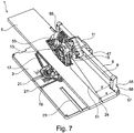
- the provision of the guide pins in the slots 21', 21 means that when the fence assembly is moved along the guide means 21,21' the contact surface 19 is retained in the parallel relationship as shown in Figure 7 .
- the guide pin can be moved to a position to protrude or is biased into a position to protrude into the guide means 21' when the fence assembly is to be used for this purpose while the guide pin to be received in slot 21 may also be biased or is fixed in a protruding position.
- the positioning of the fence assembly (17) in this manner allows the user to make cuts in the work piece (5) generally along its length and with the grain (rip cuts) with the work piece (5) secured in position.
- the ramp has an open end at the edge which is lower so that the guide pin initially hits that when the fence is being moved onto the slot 23 and as the fence is moved inwardly from the edge the contact between the rising ramp portion and the guide pin causes the guide pin to move up so that the free end is at the level of the top surface of the base, typically against a biasing force provided by a spring, to a retracted position within the fence and so does not provide any guiding effect.
- the fence is movable about pivot point (25) and this allows the fence contact surface 19 to be angularly adjustable and allows the work piece (5) to be cut at various angles selected by the user (mitre cuts and cross cuts) as illustrated in Figures 3a-d .
- Third guide means (45, 45') are provided on the base (3) for positioning the fence assembly (17) to the opposing side of the apparatus (1) from the first guide means as is illustrated in Figure 5 and Figures 9a-b (i.e. such that the fence can be located underneath the slide members (9) and on the same side of the cutting line 24 of the rotatable blade as the guide rails (9)). This is provided such that a user can perform cuts on larger work pieces (5').
- the arrangement of the third guide means (45, 45') is similar to that of the first rail means (21, 21') in that two parallel slots (45, 45') run perpendicular to the cutting line 24 of the rotatable blade are provided, such that when the fence (17) is located on the third guide means (45, 45'), it remains fixed so the contact surface (19) runs in a plane substantially parallel with the cutting plane of the rotatable blade.
- the cutting apparatus (1) described in the present application therefore has the advantage that the fence (17) that is provided on the base (3) and when in located on the second rail means (23) is adjustable about a wide range of angles, allowing a work piece (5) to be cut to fit its location with much greater accuracy and the provision of the first and third guide means allows the provision of a parallel contact surface to be provided on the base at a number of different locations whilst, importantly, still being able to use the same fence.
- the apparatus (1) of the present invention provides a user with the facility to make suitable cross cuts, rip cuts, and a wide variety of mitre cuts on a work piece (5).
- Figure 10 illustrates the possible location of the fence 17 on the three guide means 21, 23 and 45 for the purposes of illustration and illustrates via arrows 69, 71,73 and 75 the possible movement of the fence assembly when located on each of the guide means.
- a locking assembly (27) in the form of threaded bolts, screws and/or a cam mechanism.
- a further bolt (29) is provided to run along the second and parallel slot (21'; 45'). This ensures the contact surface (19) of the fence assembly (17) is maintained in a fixed plane parallel to the cutting plane of the blade and results in an accurate rip cut along the work piece (5) when such a cut is required.
- the fence assembly (17) can be moved along the slots (21, 21'; 45,45') to suit the width of the work piece (5) and the cut that is required.
- the location of the first guide means is provided such that the cutting line 24 of the rotatable blade is between the first guide means and the slide members (9).
- the contact face (19) of the fence (17) is angularly adjustable about the pivot point (25) and once the angular adjustment of the fence assembly (17) is achieved, the threaded screw or bolt (31) which rests in the fence slot (33) can be tightened.
- a further slot (35) is provided in the fence assembly (17) in which an angle pointer (37) connected to the base (3) lies. The extent of length of the slot (35) determines the degree of angular adjustment that will be possible.
- the cut can be directly across at 90 0 or a range of predetermined angular positions such as macro angles of plus or minus 15 0 , 20 0 , 22.5 0 , 30 0 , 45 0 to be achieved are defined.
- the user may position the work piece (5) across a broad range of angles with respect to the cutting plane of the rotatable blade, providing an increased number of mitre cutting options for the user.
- a clamp device (39) is provided with the apparatus (1) and includes a threaded rod (41) with a foot (43).
- the foot (43) is formed so as to prevent damage to the work piece (5) against which the same is clamped.
- This clamp (39) is therefore used to maintain the work piece (5) in a position on the base (3) while the user performs the cutting action.
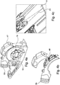
- the guard (15) of the cutting unit (13) is provided with an adjustable cutting guideline generator (47) as is illustrated with reference to Figures 4a-c .
- the generator (47) includes a laser generator (49) with the leading face being formed so as to ensure that there is a free path along the cutting line 24 of the work piece (5) for a guideline (51) which is generated.
- other illumination means such as LEDs
- the cutting guide (47) as herein described may be used on other designs and cutting apparatus and is not confined to use with the apparatus (1) herein described.
- the position of the laser generator (49) on the guard (15) is adjustable, allowing the guideline (51) that is produced to be aligned with the line of the cut, or both or either side of the kerf of the cutting blade.
- the guard (15) can also be provided with, or have attached thereto, a dust collection channel (53) through which dust or debris created during the cutting operation of the blade can be removed from the vicinity, allowing the dust and debris to be collected. Collection of the dust and debris can by a bag connected to the channel (53) or by other vacuum apparatus. Typically the dust and debris is collected from the cut area by the airflow created by rotation of the blade and carried upwardly and around the guard (15) by the airflow to an exit aperture, typically located at a tangent to the airflow above the blade.
- the slide members (9) of the cutting apparatus (1) are supported in place by a pair of support legs (55).
- each of the support legs (55) are provided so as to be placed at a distance X from the cutting line which is greater than the distance Y of the remainder of the support legs from the cutting line 24 as illustrated in, for example, Figure 7 .
- the dog-leg profile (57) is provided on the support legs (55) such that the lower portions 56 of the respective support legs (55) are located outwardly from the cutting plane of the rotatable blade with respect to the upper portion of the support legs (55) and hence allows the receipt of the edge of a workpiece 5 at the lower portions 56 and so increasing the width of the work piece (5) that may be cut, as depicted in Figure 7 .
- FIGS 8a and b there is shown one form of the apparatus in which there is provided a pushing member 61 which can be used to guide the movement of a workpiece past the cutting blade in one embodiment of use of the apparatus.
- the member has a series of formations 63 which can be used to contact the workpiece and move the same and thereby avoids the need for the user to contact the workpiece directly in order to move the same and hence avoids the need for the user to place there hands close to the cutting blade in operation of the apparatus.
- the pushing member 61 is located for storage in a housing 65 located on the underside 67 of the base 3 as shown.
Landscapes
- Life Sciences & Earth Sciences (AREA)
- Engineering & Computer Science (AREA)
- Mechanical Engineering (AREA)
- Wood Science & Technology (AREA)
- Forests & Forestry (AREA)
- Sawing (AREA)
Claims (16)
- Kraftbetriebene Schneidvorrichtung (1), wobei die genannte Vorrichtung eine Basis (3) mit einer Oberfläche, auf die ein zu schneidendes Werkstück (5) gelegt werden kann, ein erstes und ein zweites paralleles Schiebeelement (9), die voneinander beabstandet sind, einen Anschlag (17) mit einer Oberfläche (19) zur Anlage des Werkstücks (5) daran und eine Schneideinheit (13) aufweist, wobei die genannte Schneideinheit eine rotationsfähiges Blatt (16), einen Schutz (15) für dasselbe und ein Antriebsmittel zum Drehen des genannten Blatts (16), wenn es eingeschaltet ist, beinhaltet, wobei die genannte Schneideinheit (13) an und an einer Seite von den Schiebeelementen (9) montiert ist, so dass das Blatt (16) auf einer Seite derselben entlang einer Ebene, die zu der genannten Oberfläche der Basis (3) im Wesentlichen parallel ist, beabstandet ist; wobei die Basis (3) erste Führungsmittel (21, 21') beinhaltet, die zum Fixieren des genannten Anschlags (17) über einen ersten und einen zweiten an dem Anschlag (17) bereitgestellten Stift bereitgestellt sind, so dass die genannte Anschlagoberfläche (19) in einer Ebene positioniert ist, die im Wesentlichen parallel zur Längsachse der genannten Schieber (9) positioniert ist, und dadurch gekennzeichnet, dass wenigstens zweite Führungsmittel (23) bereitgestellt sind, mit dem der genannte Anschlag (17) über einen der genannten Stifte fixiert wird, wobei der andere der genannten Stifte zurückgezogen ist, damit die Position des genannten Anschlags (17) von einem Benutzer winklig eingestellt werden kann.
- Vorrichtung nach Anspruch 1, wobei der Anschlag (17) wahlweise an einer von einer Reihe von vorbestimmten Winkelpositionen positionierbar ist.
- Vorrichtung nach Anspruch 1, wobei die Positionierung des Anschlags (17) an den genannten ersten (21, 21') und/oder zweiten (23) Führungsmitteln vom Benutzer gewählt wird und dann mit einem oder mehr Sicherungsmitteln (27) arretiert wird.
- Vorrichtung nach Anspruch 1, wobei die genannten ersten Führungsmittel als mehrere Aussparungen (21, 21') an der Basis (3) der Vorrichtung bereitgestellt sind.
- Vorrichtung nach Anspruch 4, wobei die genannten ersten Führungsmittel (21, 21') sich in der Vorrichtung befinden, so dass die Schnittlinie des rotationsfähigen Blatts (16) zwischen den ersten Führungsmitteln (21, 21') und den Schiebeelementen (9) liegt.
- Vorrichtung nach Anspruch 4, wobei die Länge der genannten Aussparungen (21, 21') das Ausmaß der Verstellung der Position einer Kontaktfläche (19) des genannten Anschlags (17) definiert und die Bewegung des Anschlags (17) so führt, dass die Kontaktfläche (19) des Anschlags (17) in einer im Wesentlichen parallelen Beziehung zur Schneidebene des rotationsfähigen Blatts (16) gehalten wird.
- Vorrichtung nach Anspruch 1, wobei das genannte zweite Führungsmittel eine Aussparung (23) auf der Basis (3) der Vorrichtung beinhaltet und der genannte Anschlag (17) in Bezug auf die genannte Aussparung (23) drehbar einstellbar ist, was die winklige Einstellung einer Kontaktfläche (19) des genannten Anschlags (17) ermöglicht, und an der das Werkstück (5) in Anlage ist.
- Vorrichtung nach Anspruch 1, wobei der genannte Anschlag (17) schwenkbar bewegbar ist, wenn er an dem zweiten Führungsmittel (23) in Anlage ist, um die winklige Einstellung innerhalb eines vorbestimmten Bereichs von ±45° zuzulassen.
- Vorrichtung nach Anspruch 1, wobei der genannte Anschlag (17) eine Klemmeinrichtung (39) zum Festspannen des Werkstücks (5) in Solllage beinhaltet.
- Vorrichtung nach einem der vorhergehenden Ansprüche, wobei wenigstens ein drittes Führungsmittel (45, 45') bereitgestellt ist und auf derselben Seite der Schnittlinie des rotationsfähigen Blatts (16) liegt wie die genannten Schiebeelemente (9).
- Vorrichtung nach Anspruch 10, wobei das genannte dritte Führungsmittel (45, 45') in der Basis (3) im Wesentlichen unterhalb der genannten Schiebeelemente (9) liegt.
- Vorrichtung nach Anspruch 1, wobei die Vorrichtung ferner einen einstellbaren Schneidführungsliniengenerator (47) beinhaltet, der auf der Schneideinheit (13) montiert ist.
- Vorrichtung nach Anspruch 12, wobei der genannte einstellbare Schneidführungsliniengenerator (47) zum Erzeugen einer Laser- oder einer LED-Führungslinie auf dem zu schneidenden Werkstück (5) bereitgestellt ist.
- Vorrichtung nach Anspruch 12, wobei die Position des Generators (47) an der Schneideinheit (13) einstellbar ist, damit die von dem Generator (47) erzeugte Führungslinie auf die Schnittlinie oder beide oder eine Seite(n) der Schnittfuge des Blatts (16) ausgerichtet werden kann.
- Vorrichtung nach Anspruch 1, wobei die Schiebeelemente (9) der kraftbetriebenen Schneidvorrichtung Stützen (55) aufweisen, um dieselben in Bezug auf die Basis (3) in Solllage zu halten, und wenigstens eine der genannten Stützen (55) mit einem sich an die Basis (3) angrenzend befindlichen Teil (57) versehen ist, der sich in einem weiteren Abstand von der Schnittlinie des rotationsfähigen Blatts befindet als ein anderer Teil der Stütze (55).
- Vorrichtung nach Anspruch 15, wobei mehrere Stützen (55) mit derselben Form bereitgestellt sind und mit den Schiebeelementen (9) fixiert werden, um dieselben an beabstandeten Stellen daran entlang zu stützen.
Applications Claiming Priority (2)
| Application Number | Priority Date | Filing Date | Title |
|---|---|---|---|
| GBGB1307756.5A GB201307756D0 (en) | 2013-04-30 | 2013-04-30 | Power tool |
| PCT/GB2014/050664 WO2014177831A1 (en) | 2013-04-30 | 2014-03-06 | Power tool |
Publications (2)
| Publication Number | Publication Date |
|---|---|
| EP2869975A1 EP2869975A1 (de) | 2015-05-13 |
| EP2869975B1 true EP2869975B1 (de) | 2017-02-22 |
Family
ID=48627041
Family Applications (1)
| Application Number | Title | Priority Date | Filing Date |
|---|---|---|---|
| EP14715059.3A Active EP2869975B1 (de) | 2013-04-30 | 2014-03-06 | Elektrowerkzeug |
Country Status (7)
| Country | Link |
|---|---|
| US (1) | US10363682B2 (de) |
| EP (1) | EP2869975B1 (de) |
| CN (1) | CN104487213B (de) |
| AU (1) | AU2014261255B2 (de) |
| ES (1) | ES2620355T3 (de) |
| GB (2) | GB201307756D0 (de) |
| WO (1) | WO2014177831A1 (de) |
Families Citing this family (8)
| Publication number | Priority date | Publication date | Assignee | Title |
|---|---|---|---|---|
| CN110202644B (zh) * | 2019-06-24 | 2021-09-14 | 郑微丹 | 定位型锯料装置 |
| US11642809B2 (en) * | 2020-03-24 | 2023-05-09 | Woodpeckers, Llc | Track square with adjustable mechanism |
| WO2022109381A1 (en) | 2020-11-23 | 2022-05-27 | Milwaukee Electric Tool Corporation | Track saw assembly |
| US11628587B2 (en) * | 2021-02-24 | 2023-04-18 | Techtronic Cordless Gp | Floor saw with blade guard |
| US12465982B2 (en) | 2022-02-24 | 2025-11-11 | Techtronic Cordless Gp | Track saw including plunge lockout mechanism |
| US12441022B2 (en) * | 2022-08-08 | 2025-10-14 | Woodpeckers, Llc | Table saw jig and method of use |
| US12083613B2 (en) | 2022-10-18 | 2024-09-10 | Techtronic Cordless Gp | Track saw including plunge lockout mechanism |
| GB2624424B (en) * | 2022-11-17 | 2025-01-08 | Baxter Jody | A saw guide device |
Citations (1)
| Publication number | Priority date | Publication date | Assignee | Title |
|---|---|---|---|---|
| US4995288A (en) * | 1988-10-03 | 1991-02-26 | Dellapolla Michael | Saw guide |
Family Cites Families (12)
| Publication number | Priority date | Publication date | Assignee | Title |
|---|---|---|---|---|
| US2601878A (en) * | 1946-03-08 | 1952-07-01 | St Paul Foundry & Mfg Co | Table saw with part of the table swingably and laterally adjustable |
| DE2544239C3 (de) * | 1975-10-03 | 1979-02-15 | Manfred 3204 Nordstemmen Dyck | Stanz- und Schnittwerkzeug mit auswechselbaren Schnittplatten |
| US5233891A (en) * | 1991-09-06 | 1993-08-10 | Easco Hand Tools, Inc. | Detent means |
| TW467783B (en) * | 1998-02-13 | 2001-12-11 | Black & Amp Decker Inc | Table saw |
| US20030075033A1 (en) * | 2001-04-03 | 2003-04-24 | Speakman John David | Workpiece support accessory for table-mounted power saw |
| US20060201299A1 (en) * | 2003-01-21 | 2006-09-14 | Santa Ana Roland C | Combination table-mitter saw & assembly |
| US7066627B1 (en) * | 2004-12-07 | 2006-06-27 | Yueh-Ting Chen | Laser light beam guiding device on a stone cutter |
| GB0723700D0 (en) * | 2007-12-04 | 2008-01-16 | Gmca Pty Ltd | Power tool cutting apparatus |
| US8186257B2 (en) | 2008-08-27 | 2012-05-29 | Robert Bosch Gmbh | Laminate flooring saw |
| US8549971B2 (en) * | 2008-08-27 | 2013-10-08 | Robert Bosch Gmbh | Laminate flooring saw |
| CN201525008U (zh) * | 2009-10-13 | 2010-07-14 | 南京德朔实业有限公司 | 用于电动工具上的导向装置 |
| DE102010041927A1 (de) * | 2010-10-04 | 2012-04-05 | Robert Bosch Gmbh | Werkstückführungsvorrichtung |
-
2013
- 2013-04-30 GB GBGB1307756.5A patent/GB201307756D0/en not_active Ceased
-
2014
- 2014-03-06 ES ES14715059.3T patent/ES2620355T3/es active Active
- 2014-03-06 AU AU2014261255A patent/AU2014261255B2/en active Active
- 2014-03-06 WO PCT/GB2014/050664 patent/WO2014177831A1/en not_active Ceased
- 2014-03-06 EP EP14715059.3A patent/EP2869975B1/de active Active
- 2014-03-06 GB GB1422376.2A patent/GB2518089B/en active Active
- 2014-03-06 US US14/414,656 patent/US10363682B2/en active Active
- 2014-03-06 CN CN201480001892.5A patent/CN104487213B/zh active Active
Patent Citations (1)
| Publication number | Priority date | Publication date | Assignee | Title |
|---|---|---|---|---|
| US4995288A (en) * | 1988-10-03 | 1991-02-26 | Dellapolla Michael | Saw guide |
Also Published As
| Publication number | Publication date |
|---|---|
| WO2014177831A1 (en) | 2014-11-06 |
| CN104487213B (zh) | 2018-03-23 |
| US20160075051A1 (en) | 2016-03-17 |
| CN104487213A (zh) | 2015-04-01 |
| ES2620355T3 (es) | 2017-06-28 |
| US10363682B2 (en) | 2019-07-30 |
| GB201307756D0 (en) | 2013-06-12 |
| GB2518089A (en) | 2015-03-11 |
| AU2014261255A1 (en) | 2015-01-22 |
| AU2014261255B2 (en) | 2017-06-08 |
| EP2869975A1 (de) | 2015-05-13 |
| GB2518089B (en) | 2018-08-01 |
Similar Documents
| Publication | Publication Date | Title |
|---|---|---|
| EP2869975B1 (de) | Elektrowerkzeug | |
| US11458648B2 (en) | Power tool cutting apparatus | |
| US6370997B1 (en) | Transportable bench circular saw | |
| US5035061A (en) | Guide for hand-held power tools | |
| US10661467B2 (en) | Miter saw with adjustable fence | |
| US4133237A (en) | Work table for saws and other tools | |
| US8671811B2 (en) | Pivoting saw system | |
| US20080197555A1 (en) | Positioning system for work piece milling | |
| US3727502A (en) | Saw-table construction | |
| US4050340A (en) | Power tool track | |
| EP3348366A1 (de) | Schneidwerkzeug mit verstellbarem schneidmesser | |
| US20110132167A1 (en) | Circular and miter box saw | |
| US20140238212A1 (en) | Saw guide | |
| US6374879B1 (en) | Carpentry coping machine | |
| US5484003A (en) | Chop saw table | |
| US10668546B2 (en) | Miter cutting slide for jig saw | |
| US5319857A (en) | Construction board miter guide | |
| US20190337184A1 (en) | Magic perfect mitre | |
| US20080006343A1 (en) | Electric trim saw | |
| SE525965C2 (sv) | Skärbord för tillskärning av isoleringsmaterial |
Legal Events
| Date | Code | Title | Description |
|---|---|---|---|
| PUAI | Public reference made under article 153(3) epc to a published international application that has entered the european phase |
Free format text: ORIGINAL CODE: 0009012 |
|
| 17P | Request for examination filed |
Effective date: 20141216 |
|
| AK | Designated contracting states |
Kind code of ref document: A1 Designated state(s): AL AT BE BG CH CY CZ DE DK EE ES FI FR GB GR HR HU IE IS IT LI LT LU LV MC MK MT NL NO PL PT RO RS SE SI SK SM TR |
|
| AX | Request for extension of the european patent |
Extension state: BA ME |
|
| 17Q | First examination report despatched |
Effective date: 20151223 |
|
| DAX | Request for extension of the european patent (deleted) | ||
| REG | Reference to a national code |
Ref country code: DE Ref legal event code: R079 Ref document number: 602014006926 Country of ref document: DE Free format text: PREVIOUS MAIN CLASS: B27B0027080000 Ipc: B27B0027020000 |
|
| RIC1 | Information provided on ipc code assigned before grant |
Ipc: B27B 5/18 20060101ALI20160822BHEP Ipc: B27B 27/06 20060101ALI20160822BHEP Ipc: B27B 27/08 20060101ALI20160822BHEP Ipc: B27B 27/02 20060101AFI20160822BHEP |
|
| GRAP | Despatch of communication of intention to grant a patent |
Free format text: ORIGINAL CODE: EPIDOSNIGR1 |
|
| INTG | Intention to grant announced |
Effective date: 20161018 |
|
| GRAS | Grant fee paid |
Free format text: ORIGINAL CODE: EPIDOSNIGR3 |
|
| GRAA | (expected) grant |
Free format text: ORIGINAL CODE: 0009210 |
|
| AK | Designated contracting states |
Kind code of ref document: B1 Designated state(s): AL AT BE BG CH CY CZ DE DK EE ES FI FR GB GR HR HU IE IS IT LI LT LU LV MC MK MT NL NO PL PT RO RS SE SI SK SM TR |
|
| REG | Reference to a national code |
Ref country code: GB Ref legal event code: FG4D |
|
| REG | Reference to a national code |
Ref country code: CH Ref legal event code: EP |
|
| REG | Reference to a national code |
Ref country code: AT Ref legal event code: REF Ref document number: 868902 Country of ref document: AT Kind code of ref document: T Effective date: 20170315 |
|
| REG | Reference to a national code |
Ref country code: FR Ref legal event code: PLFP Year of fee payment: 4 |
|
| REG | Reference to a national code |
Ref country code: IE Ref legal event code: FG4D |
|
| REG | Reference to a national code |
Ref country code: DE Ref legal event code: R096 Ref document number: 602014006926 Country of ref document: DE |
|
| REG | Reference to a national code |
Ref country code: LT Ref legal event code: MG4D |
|
| REG | Reference to a national code |
Ref country code: ES Ref legal event code: FG2A Ref document number: 2620355 Country of ref document: ES Kind code of ref document: T3 Effective date: 20170628 Ref country code: NL Ref legal event code: MP Effective date: 20170222 |
|
| REG | Reference to a national code |
Ref country code: AT Ref legal event code: MK05 Ref document number: 868902 Country of ref document: AT Kind code of ref document: T Effective date: 20170222 |
|
| PG25 | Lapsed in a contracting state [announced via postgrant information from national office to epo] |
Ref country code: LT Free format text: LAPSE BECAUSE OF FAILURE TO SUBMIT A TRANSLATION OF THE DESCRIPTION OR TO PAY THE FEE WITHIN THE PRESCRIBED TIME-LIMIT Effective date: 20170222 Ref country code: HR Free format text: LAPSE BECAUSE OF FAILURE TO SUBMIT A TRANSLATION OF THE DESCRIPTION OR TO PAY THE FEE WITHIN THE PRESCRIBED TIME-LIMIT Effective date: 20170222 Ref country code: GR Free format text: LAPSE BECAUSE OF FAILURE TO SUBMIT A TRANSLATION OF THE DESCRIPTION OR TO PAY THE FEE WITHIN THE PRESCRIBED TIME-LIMIT Effective date: 20170523 Ref country code: NO Free format text: LAPSE BECAUSE OF FAILURE TO SUBMIT A TRANSLATION OF THE DESCRIPTION OR TO PAY THE FEE WITHIN THE PRESCRIBED TIME-LIMIT Effective date: 20170522 Ref country code: FI Free format text: LAPSE BECAUSE OF FAILURE TO SUBMIT A TRANSLATION OF THE DESCRIPTION OR TO PAY THE FEE WITHIN THE PRESCRIBED TIME-LIMIT Effective date: 20170222 |
|
| PG25 | Lapsed in a contracting state [announced via postgrant information from national office to epo] |
Ref country code: NL Free format text: LAPSE BECAUSE OF FAILURE TO SUBMIT A TRANSLATION OF THE DESCRIPTION OR TO PAY THE FEE WITHIN THE PRESCRIBED TIME-LIMIT Effective date: 20170222 Ref country code: SE Free format text: LAPSE BECAUSE OF FAILURE TO SUBMIT A TRANSLATION OF THE DESCRIPTION OR TO PAY THE FEE WITHIN THE PRESCRIBED TIME-LIMIT Effective date: 20170222 Ref country code: LV Free format text: LAPSE BECAUSE OF FAILURE TO SUBMIT A TRANSLATION OF THE DESCRIPTION OR TO PAY THE FEE WITHIN THE PRESCRIBED TIME-LIMIT Effective date: 20170222 Ref country code: BG Free format text: LAPSE BECAUSE OF FAILURE TO SUBMIT A TRANSLATION OF THE DESCRIPTION OR TO PAY THE FEE WITHIN THE PRESCRIBED TIME-LIMIT Effective date: 20170522 Ref country code: RS Free format text: LAPSE BECAUSE OF FAILURE TO SUBMIT A TRANSLATION OF THE DESCRIPTION OR TO PAY THE FEE WITHIN THE PRESCRIBED TIME-LIMIT Effective date: 20170222 Ref country code: AT Free format text: LAPSE BECAUSE OF FAILURE TO SUBMIT A TRANSLATION OF THE DESCRIPTION OR TO PAY THE FEE WITHIN THE PRESCRIBED TIME-LIMIT Effective date: 20170222 Ref country code: PT Free format text: LAPSE BECAUSE OF FAILURE TO SUBMIT A TRANSLATION OF THE DESCRIPTION OR TO PAY THE FEE WITHIN THE PRESCRIBED TIME-LIMIT Effective date: 20170622 |
|
| PG25 | Lapsed in a contracting state [announced via postgrant information from national office to epo] |
Ref country code: CZ Free format text: LAPSE BECAUSE OF FAILURE TO SUBMIT A TRANSLATION OF THE DESCRIPTION OR TO PAY THE FEE WITHIN THE PRESCRIBED TIME-LIMIT Effective date: 20170222 Ref country code: RO Free format text: LAPSE BECAUSE OF FAILURE TO SUBMIT A TRANSLATION OF THE DESCRIPTION OR TO PAY THE FEE WITHIN THE PRESCRIBED TIME-LIMIT Effective date: 20170222 Ref country code: SK Free format text: LAPSE BECAUSE OF FAILURE TO SUBMIT A TRANSLATION OF THE DESCRIPTION OR TO PAY THE FEE WITHIN THE PRESCRIBED TIME-LIMIT Effective date: 20170222 Ref country code: EE Free format text: LAPSE BECAUSE OF FAILURE TO SUBMIT A TRANSLATION OF THE DESCRIPTION OR TO PAY THE FEE WITHIN THE PRESCRIBED TIME-LIMIT Effective date: 20170222 |
|
| REG | Reference to a national code |
Ref country code: DE Ref legal event code: R097 Ref document number: 602014006926 Country of ref document: DE |
|
| PG25 | Lapsed in a contracting state [announced via postgrant information from national office to epo] |
Ref country code: PL Free format text: LAPSE BECAUSE OF FAILURE TO SUBMIT A TRANSLATION OF THE DESCRIPTION OR TO PAY THE FEE WITHIN THE PRESCRIBED TIME-LIMIT Effective date: 20170222 Ref country code: SM Free format text: LAPSE BECAUSE OF FAILURE TO SUBMIT A TRANSLATION OF THE DESCRIPTION OR TO PAY THE FEE WITHIN THE PRESCRIBED TIME-LIMIT Effective date: 20170222 Ref country code: MC Free format text: LAPSE BECAUSE OF FAILURE TO SUBMIT A TRANSLATION OF THE DESCRIPTION OR TO PAY THE FEE WITHIN THE PRESCRIBED TIME-LIMIT Effective date: 20170222 Ref country code: DK Free format text: LAPSE BECAUSE OF FAILURE TO SUBMIT A TRANSLATION OF THE DESCRIPTION OR TO PAY THE FEE WITHIN THE PRESCRIBED TIME-LIMIT Effective date: 20170222 |
|
| REG | Reference to a national code |
Ref country code: IE Ref legal event code: MM4A |
|
| PLBE | No opposition filed within time limit |
Free format text: ORIGINAL CODE: 0009261 |
|
| STAA | Information on the status of an ep patent application or granted ep patent |
Free format text: STATUS: NO OPPOSITION FILED WITHIN TIME LIMIT |
|
| 26N | No opposition filed |
Effective date: 20171123 |
|
| PG25 | Lapsed in a contracting state [announced via postgrant information from national office to epo] |
Ref country code: LU Free format text: LAPSE BECAUSE OF NON-PAYMENT OF DUE FEES Effective date: 20170306 |
|
| REG | Reference to a national code |
Ref country code: FR Ref legal event code: PLFP Year of fee payment: 5 |
|
| PG25 | Lapsed in a contracting state [announced via postgrant information from national office to epo] |
Ref country code: IE Free format text: LAPSE BECAUSE OF NON-PAYMENT OF DUE FEES Effective date: 20170306 Ref country code: SI Free format text: LAPSE BECAUSE OF FAILURE TO SUBMIT A TRANSLATION OF THE DESCRIPTION OR TO PAY THE FEE WITHIN THE PRESCRIBED TIME-LIMIT Effective date: 20170222 |
|
| REG | Reference to a national code |
Ref country code: BE Ref legal event code: MM Effective date: 20170331 |
|
| PG25 | Lapsed in a contracting state [announced via postgrant information from national office to epo] |
Ref country code: BE Free format text: LAPSE BECAUSE OF NON-PAYMENT OF DUE FEES Effective date: 20170331 |
|
| PG25 | Lapsed in a contracting state [announced via postgrant information from national office to epo] |
Ref country code: MT Free format text: LAPSE BECAUSE OF NON-PAYMENT OF DUE FEES Effective date: 20170306 |
|
| PG25 | Lapsed in a contracting state [announced via postgrant information from national office to epo] |
Ref country code: HU Free format text: LAPSE BECAUSE OF FAILURE TO SUBMIT A TRANSLATION OF THE DESCRIPTION OR TO PAY THE FEE WITHIN THE PRESCRIBED TIME-LIMIT; INVALID AB INITIO Effective date: 20140306 |
|
| PG25 | Lapsed in a contracting state [announced via postgrant information from national office to epo] |
Ref country code: CY Free format text: LAPSE BECAUSE OF FAILURE TO SUBMIT A TRANSLATION OF THE DESCRIPTION OR TO PAY THE FEE WITHIN THE PRESCRIBED TIME-LIMIT Effective date: 20170222 |
|
| PG25 | Lapsed in a contracting state [announced via postgrant information from national office to epo] |
Ref country code: MK Free format text: LAPSE BECAUSE OF FAILURE TO SUBMIT A TRANSLATION OF THE DESCRIPTION OR TO PAY THE FEE WITHIN THE PRESCRIBED TIME-LIMIT Effective date: 20170222 |
|
| PG25 | Lapsed in a contracting state [announced via postgrant information from national office to epo] |
Ref country code: TR Free format text: LAPSE BECAUSE OF FAILURE TO SUBMIT A TRANSLATION OF THE DESCRIPTION OR TO PAY THE FEE WITHIN THE PRESCRIBED TIME-LIMIT Effective date: 20170222 |
|
| PG25 | Lapsed in a contracting state [announced via postgrant information from national office to epo] |
Ref country code: AL Free format text: LAPSE BECAUSE OF FAILURE TO SUBMIT A TRANSLATION OF THE DESCRIPTION OR TO PAY THE FEE WITHIN THE PRESCRIBED TIME-LIMIT Effective date: 20170222 Ref country code: IS Free format text: LAPSE BECAUSE OF FAILURE TO SUBMIT A TRANSLATION OF THE DESCRIPTION OR TO PAY THE FEE WITHIN THE PRESCRIBED TIME-LIMIT Effective date: 20170622 |
|
| P01 | Opt-out of the competence of the unified patent court (upc) registered |
Effective date: 20230403 |
|
| PGFP | Annual fee paid to national office [announced via postgrant information from national office to epo] |
Ref country code: IT Payment date: 20240326 Year of fee payment: 11 |
|
| PGFP | Annual fee paid to national office [announced via postgrant information from national office to epo] |
Ref country code: CH Payment date: 20240401 Year of fee payment: 11 |
|
| PGFP | Annual fee paid to national office [announced via postgrant information from national office to epo] |
Ref country code: ES Payment date: 20240402 Year of fee payment: 11 |
|
| REG | Reference to a national code |
Ref country code: GB Ref legal event code: 732E Free format text: REGISTERED BETWEEN 20250424 AND 20250430 |
|
| REG | Reference to a national code |
Ref country code: CH Ref legal event code: H13 Free format text: ST27 STATUS EVENT CODE: U-0-0-H10-H13 (AS PROVIDED BY THE NATIONAL OFFICE) Effective date: 20251023 |
|
| PG25 | Lapsed in a contracting state [announced via postgrant information from national office to epo] |
Ref country code: IT Free format text: LAPSE BECAUSE OF NON-PAYMENT OF DUE FEES Effective date: 20250306 |
|
| PG25 | Lapsed in a contracting state [announced via postgrant information from national office to epo] |
Ref country code: CH Free format text: LAPSE BECAUSE OF NON-PAYMENT OF DUE FEES Effective date: 20250331 |
|
| PGFP | Annual fee paid to national office [announced via postgrant information from national office to epo] |
Ref country code: GB Payment date: 20260310 Year of fee payment: 13 |
|
| PGFP | Annual fee paid to national office [announced via postgrant information from national office to epo] |
Ref country code: DE Payment date: 20260311 Year of fee payment: 13 |
|
| PGFP | Annual fee paid to national office [announced via postgrant information from national office to epo] |
Ref country code: FR Payment date: 20260310 Year of fee payment: 13 |
|
| REG | Reference to a national code |
Ref country code: ES Ref legal event code: FD2A Effective date: 20260428 |