EP2870403B1 - Druckgasflasche mit ventilschutzeinrichtung - Google Patents
Druckgasflasche mit ventilschutzeinrichtung Download PDFInfo
- Publication number
- EP2870403B1 EP2870403B1 EP13730239.4A EP13730239A EP2870403B1 EP 2870403 B1 EP2870403 B1 EP 2870403B1 EP 13730239 A EP13730239 A EP 13730239A EP 2870403 B1 EP2870403 B1 EP 2870403B1
- Authority
- EP
- European Patent Office
- Prior art keywords
- valve
- protection device
- valve protection
- securing element
- tamper
- Prior art date
- Legal status (The legal status is an assumption and is not a legal conclusion. Google has not performed a legal analysis and makes no representation as to the accuracy of the status listed.)
- Active
Links
Images

Classifications
-
- F—MECHANICAL ENGINEERING; LIGHTING; HEATING; WEAPONS; BLASTING
- F17—STORING OR DISTRIBUTING GASES OR LIQUIDS
- F17C—VESSELS FOR CONTAINING OR STORING COMPRESSED, LIQUEFIED OR SOLIDIFIED GASES; FIXED-CAPACITY GAS-HOLDERS; FILLING VESSELS WITH, OR DISCHARGING FROM VESSELS, COMPRESSED, LIQUEFIED, OR SOLIDIFIED GASES
- F17C13/00—Details of vessels or of the filling or discharging of vessels
- F17C13/002—Details of vessels or of the filling or discharging of vessels for vessels under pressure
-
- F—MECHANICAL ENGINEERING; LIGHTING; HEATING; WEAPONS; BLASTING
- F17—STORING OR DISTRIBUTING GASES OR LIQUIDS
- F17C—VESSELS FOR CONTAINING OR STORING COMPRESSED, LIQUEFIED OR SOLIDIFIED GASES; FIXED-CAPACITY GAS-HOLDERS; FILLING VESSELS WITH, OR DISCHARGING FROM VESSELS, COMPRESSED, LIQUEFIED, OR SOLIDIFIED GASES
- F17C2201/00—Vessel construction, in particular geometry, arrangement or size
- F17C2201/01—Shape
- F17C2201/0104—Shape cylindrical
-
- F—MECHANICAL ENGINEERING; LIGHTING; HEATING; WEAPONS; BLASTING
- F17—STORING OR DISTRIBUTING GASES OR LIQUIDS
- F17C—VESSELS FOR CONTAINING OR STORING COMPRESSED, LIQUEFIED OR SOLIDIFIED GASES; FIXED-CAPACITY GAS-HOLDERS; FILLING VESSELS WITH, OR DISCHARGING FROM VESSELS, COMPRESSED, LIQUEFIED, OR SOLIDIFIED GASES
- F17C2201/00—Vessel construction, in particular geometry, arrangement or size
- F17C2201/03—Orientation
- F17C2201/032—Orientation with substantially vertical main axis
-
- F—MECHANICAL ENGINEERING; LIGHTING; HEATING; WEAPONS; BLASTING
- F17—STORING OR DISTRIBUTING GASES OR LIQUIDS
- F17C—VESSELS FOR CONTAINING OR STORING COMPRESSED, LIQUEFIED OR SOLIDIFIED GASES; FIXED-CAPACITY GAS-HOLDERS; FILLING VESSELS WITH, OR DISCHARGING FROM VESSELS, COMPRESSED, LIQUEFIED, OR SOLIDIFIED GASES
- F17C2201/00—Vessel construction, in particular geometry, arrangement or size
- F17C2201/05—Size
- F17C2201/058—Size portable (<30 l)
-
- F—MECHANICAL ENGINEERING; LIGHTING; HEATING; WEAPONS; BLASTING
- F17—STORING OR DISTRIBUTING GASES OR LIQUIDS
- F17C—VESSELS FOR CONTAINING OR STORING COMPRESSED, LIQUEFIED OR SOLIDIFIED GASES; FIXED-CAPACITY GAS-HOLDERS; FILLING VESSELS WITH, OR DISCHARGING FROM VESSELS, COMPRESSED, LIQUEFIED, OR SOLIDIFIED GASES
- F17C2205/00—Vessel construction, in particular mounting arrangements, attachments or identifications means
- F17C2205/03—Fluid connections, filters, valves, closure means or other attachments
- F17C2205/0302—Fittings, valves, filters, or components in connection with the gas storage device
- F17C2205/0308—Protective caps
-
- F—MECHANICAL ENGINEERING; LIGHTING; HEATING; WEAPONS; BLASTING
- F17—STORING OR DISTRIBUTING GASES OR LIQUIDS
- F17C—VESSELS FOR CONTAINING OR STORING COMPRESSED, LIQUEFIED OR SOLIDIFIED GASES; FIXED-CAPACITY GAS-HOLDERS; FILLING VESSELS WITH, OR DISCHARGING FROM VESSELS, COMPRESSED, LIQUEFIED, OR SOLIDIFIED GASES
- F17C2205/00—Vessel construction, in particular mounting arrangements, attachments or identifications means
- F17C2205/03—Fluid connections, filters, valves, closure means or other attachments
- F17C2205/0302—Fittings, valves, filters, or components in connection with the gas storage device
- F17C2205/0323—Valves
- F17C2205/0329—Valves manually actuated
-
- F—MECHANICAL ENGINEERING; LIGHTING; HEATING; WEAPONS; BLASTING
- F17—STORING OR DISTRIBUTING GASES OR LIQUIDS
- F17C—VESSELS FOR CONTAINING OR STORING COMPRESSED, LIQUEFIED OR SOLIDIFIED GASES; FIXED-CAPACITY GAS-HOLDERS; FILLING VESSELS WITH, OR DISCHARGING FROM VESSELS, COMPRESSED, LIQUEFIED, OR SOLIDIFIED GASES
- F17C2205/00—Vessel construction, in particular mounting arrangements, attachments or identifications means
- F17C2205/05—Vessel or content identifications, e.g. labels
-
- F—MECHANICAL ENGINEERING; LIGHTING; HEATING; WEAPONS; BLASTING
- F17—STORING OR DISTRIBUTING GASES OR LIQUIDS
- F17C—VESSELS FOR CONTAINING OR STORING COMPRESSED, LIQUEFIED OR SOLIDIFIED GASES; FIXED-CAPACITY GAS-HOLDERS; FILLING VESSELS WITH, OR DISCHARGING FROM VESSELS, COMPRESSED, LIQUEFIED, OR SOLIDIFIED GASES
- F17C2223/00—Handled fluid before transfer, i.e. state of fluid when stored in the vessel or before transfer from the vessel
- F17C2223/01—Handled fluid before transfer, i.e. state of fluid when stored in the vessel or before transfer from the vessel characterised by the phase
- F17C2223/0107—Single phase
- F17C2223/0123—Single phase gaseous, e.g. CNG, GNC
-
- F—MECHANICAL ENGINEERING; LIGHTING; HEATING; WEAPONS; BLASTING
- F17—STORING OR DISTRIBUTING GASES OR LIQUIDS
- F17C—VESSELS FOR CONTAINING OR STORING COMPRESSED, LIQUEFIED OR SOLIDIFIED GASES; FIXED-CAPACITY GAS-HOLDERS; FILLING VESSELS WITH, OR DISCHARGING FROM VESSELS, COMPRESSED, LIQUEFIED, OR SOLIDIFIED GASES
- F17C2223/00—Handled fluid before transfer, i.e. state of fluid when stored in the vessel or before transfer from the vessel
- F17C2223/03—Handled fluid before transfer, i.e. state of fluid when stored in the vessel or before transfer from the vessel characterised by the pressure level
- F17C2223/035—High pressure (>10 bar)
-
- F—MECHANICAL ENGINEERING; LIGHTING; HEATING; WEAPONS; BLASTING
- F17—STORING OR DISTRIBUTING GASES OR LIQUIDS
- F17C—VESSELS FOR CONTAINING OR STORING COMPRESSED, LIQUEFIED OR SOLIDIFIED GASES; FIXED-CAPACITY GAS-HOLDERS; FILLING VESSELS WITH, OR DISCHARGING FROM VESSELS, COMPRESSED, LIQUEFIED, OR SOLIDIFIED GASES
- F17C2223/00—Handled fluid before transfer, i.e. state of fluid when stored in the vessel or before transfer from the vessel
- F17C2223/03—Handled fluid before transfer, i.e. state of fluid when stored in the vessel or before transfer from the vessel characterised by the pressure level
- F17C2223/036—Very high pressure (>80 bar)
-
- F—MECHANICAL ENGINEERING; LIGHTING; HEATING; WEAPONS; BLASTING
- F17—STORING OR DISTRIBUTING GASES OR LIQUIDS
- F17C—VESSELS FOR CONTAINING OR STORING COMPRESSED, LIQUEFIED OR SOLIDIFIED GASES; FIXED-CAPACITY GAS-HOLDERS; FILLING VESSELS WITH, OR DISCHARGING FROM VESSELS, COMPRESSED, LIQUEFIED, OR SOLIDIFIED GASES
- F17C2270/00—Applications
- F17C2270/07—Applications for household use
- F17C2270/0745—Gas bottles
Definitions
- the invention relates to a pressurized gas cylinder with a cylinder valve for filling and withdrawing gas and with a valve protection device to protect the cylinder valve from damage, the valve protection device comprising a housing mounted on a neck of the pressurized gas cylinder which is equipped with an access opening allowing access to the cylinder valve .
- valve protection device is to be understood as a safety element mounted on a pressurized gas cylinder, which basically remains on the pressurized gas cylinder during the intended use of the pressurized gas cylinder, ie in particular also when gas is withdrawn.
- valve protection devices are designed in such a way that, on the one hand, they ensure reliable protection of the cylinder valve from damage due to impact, fall or improper handling, etc., and, on the other hand, allow access to the cylinder valve and thus the removal of gas from the compressed gas cylinder without having to be removed beforehand .
- valve protection devices are known; Conventional devices of this type have, for example, the shape of a half or full shell, a bracket or a cage and are usually made of metal, e.g.
- Valve protection devices in the sense of this invention are therefore in particular not referred to as “protective cap” in the following, and are generally made of steel Safety elements that are only intended to protect the cylinder valve from damage during the transport of pressurized gas cylinders and that must be removed from the cylinder before it is used as intended, i.e. for the removal of gas or before the cylinder is filled.
- cylinder valve (or “extraction valve”) is understood here to mean the cylinder valve used to extract gas and to fill the pressurized gas container, including any fittings integrated therein, such as pressure reducers, metering and needle valves, or the like;
- pressurized gas cylinders is intended to subsume all types of containers intended for the storage of gas under pressure, in particular pressurized gas cylinders, gas cartridges or pressurized cans.
- valve protection device for gas cylinders is in EP 0 629 812 A1 described.
- This object is a plastic element with a lower part for fastening to the gas cylinder and an upper part for protecting the valve, the lower part comprising a lateral projection with a curvature as a suspension device.
- the valve protection device can be adapted to compressed gas containers of different sizes and types, for example to compressed gas cylinders with a volume of 2, 5, 10 or 20 liters.
- Further valve protection devices are, for example, in the publications EP 2 101 103 B1 , EP 0 939 875 A1 , DE 103 08 676 A1 , DE 101 46 261 A1 , DE 100 57 469 A1 or DE 199 26 961 A1 described.
- the object of the present invention is therefore to develop a pressurized gas cylinder with a valve protection device which is equipped with a reliable and inexpensive tamper-evident mechanism.
- the present invention therefore provides for a tamper-evident device adapted to the respective valve protection device to be integrated into the valve protection device, i.e. to provide means that allow the tamper-evident device to be attached to the valve protection device without great effort after the pressurized gas cylinder has been filled, and at the same time to reliably identify the tamper-evident status of the compressed gas cylinder enables.
- the means required for this include, in particular, a securing element which, when installed, extends wholly or partially over the connecting piece and / or the handwheel in such a way that the connection of a gas line or a fitting to the connecting piece or the actuation of the handwheel is impossible or significant is made more difficult, and coordinated fastening elements on the securing element of the tamper-evident on the one hand and the housing of the Valve protection device, on the other hand, which ensure that the tamper-evident device is easy to attach and cannot be removed under normal conditions without the securing element and / or the fastening elements being irreversibly damaged or changed in such a way that the tamper-evident device cannot easily be restarted the valve protection device can be installed.
- this is done by means of one or more predetermined breaking points on the securing element and / or the fastening elements, which break or break when the tamper-evident mechanism is removed.
- the invention thus enables in particular the manufacture of valve protection devices with tamper-evident security in series production, which have a constant and thus previously determinable reliability with regard to the tamper-evident identification.
- a preferred embodiment of the invention provides that the tamper-evident mechanism extends transversely or longitudinally over at least part of the access opening for the purpose of securing the cylinder valve with a securing element in such a way that the tamper-evident mechanism blocks access to the connecting piece and / or the handwheel of the cylinder valve and so that the removal of gas is prevented until the tamper-evident security is removed.
- a securing element is thus conceivable which is fastened on one side to the access opening and protrudes into the access opening or extends over it.
- a particularly advantageous embodiment provides that the securing element is connected to the housing of the valve protection device on at least two opposite sides of the access opening by means of connecting elements, with a predetermined breaking point being arranged on at least one connecting element. In the installed state, the securing element extends over the access opening in such a way that access to the connecting piece and / or the handwheel of the cylinder valve is blocked.
- the securing element In order to rule out misuse as much as possible, the securing element should lead as close as possible to the connecting piece and / or the handwheel in the installed state, so that access is not easily achieved by bending the Securing element is possible, or at least such that bending away requires a force that exceeds the tensile strength of the predetermined breaking points.
- the securing element is preferably made of a flexible material, in particular plastic, which enables the securing element to arch between the connecting elements via a handwheel and / or connecting piece in the installed state.
- the securing element preferably comprises at least one connecting element with a holding section, the shape of which is adapted to a corresponding recess in the valve protection device.
- the securing element preferably comprises at least one connecting element which, in the installed state, extends through a bore in the housing of the valve protection device and is equipped with a barb-like holding section.
- the holding section is, for example, a spherical, conical or frustoconical head section, the cross section of which is slightly larger than the inner diameter of the respective bore, and the neck section with a reduced cross section with the rest of the securing element (here called "securing section”) via a neck section that functions as a predetermined breaking point ) connected is.
- the head section is pushed through the bore and is then connected to the securing section in the manner of a barbed hook via the neck section extending through the bore.
- the neck section tears and the head section falls off; a reattachment of the securing element is then no longer easily possible.
- the securing element is preferably at least partially elastic and is under tension when installed, i.e. it is held firmly on the housing of the valve protection element under the action of a force counteracting its deformation and at the same time in its position preventing access to the cylinder valve stabilized.
- a particularly useful, easy to assemble and inexpensive securing element is a wire, a cord or a band, in particular a band made of plastic, rubber or a fabric material, which extends across the access opening in the installed state.
- a molded part made of plastic that is at least partially adapted to the opening cross-section of the access opening of the valve protection device can be used.
- Such a molded part can also be designed in such a way that it extends into the access opening with individual sections and in this way makes access to the cylinder valve difficult or impossible.
- Such a comparatively large-area securing element also offers the advantage that a user can determine the originality of the pressurized gas cylinder even from a great distance. By coloring the securing element or applying a clearly visible marking to the securing element, this advantage can also be expressed even more strongly.
- Another advantageous embodiment of the invention provides for double protection.
- the securing element serves both to secure the connection piece of the cylinder valve and to secure the handwheel required to operate the cylinder valve.
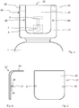
- Fig. 1 shows the upper section of a pressurized gas cylinder 1 with attached valve protection device 2, the. for example by screwing onto a thread arranged on the neck section 3 of the pressurized gas cylinder 1, to which the pressurized gas cylinder 1 is attached.
- the valve protection device 2 is preferably made of a - in particular fiber-reinforced - thermoplastic material, for. B. polyoxymethylene, polyethylene, polypropylene, polystyrene, PVC, polyester, polyamide, liquid crystalline polymer (LCP), or a blend of different plastics and serves to protect the cylinder valve 4 of the compressed gas cylinder 1.
- the valve protection device 2 comprises a housing in the form of a closed cube, which is located on at least one side surface and, when used as intended, on the upper side (geodetically seen) on its surface is equipped with access openings 5, 6. While the side access opening 5 is used to enable access to a connection piece 7 of the cylinder valve 4 for the purpose of fastening a connection line or a fitting (not shown here), the access opening 6 on the top ensures access to a handwheel 8 of the cylinder valve 4, by means of which the cylinder valve 4 can be opened or closed.
- the valve protection device 2 is equipped with a tamper-evident mechanism 9 in the manner described below.
- the tamper-evident mechanism 9 of the valve protection device 2 comprises a band 10 made of a flexible, but non-stretchable or only slightly stretchable material. In particular, it is a plastic or fabric tape.
- the band 10 is connected to the housing of the valve protection device 2 at its two ends at fastening sections 11, 12.
- the connection is made, for example, in the manner of a push-fit connection, as in FIG Fig. 3 shown in an enlarged view.
- the fastening sections 11, 12 are each equipped with a head section 13 with an enlarged diameter made of an at least partially elastic material, for example plastic, which is followed by a neck section 15 with a reduced cross section made of the same or a different material.
- the head sections 13 are provided with corresponding recesses 14, which are arranged on the housing of the valve protection device 2 in such a way that the band 10, in the installed state, lies close to the connector 7 and the handwheel 8 of the cylinder valve or only a small distance from them and in this way prevents the connection of a gas line or the actuation of the handwheel.
- the fastening sections 11, 12 are each pressed with their head sections 13 into a corresponding recess 14, a non-positive connection being established.
- the neck section 15 adjoining the head section 13 of the fastening section 11, 12 is designed in such a way that it tears when the tensile force is less than that required to detach the head section 13 from the recess 14 of the housing of the valve protection device 2. This allows the belt 10 are not removed without the fastening sections 11, 12 of the tamper-evident mechanism 9 being destroyed.
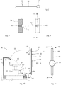
- the valve protection device 20 placed on a pressurized gas cylinder 1 comprises a half-shell-shaped housing 21 with lateral sections 22, 23 which surround the cylinder valve 4 from three sides.
- This access opening 24 is dimensioned such that it allows a gas line or a fitting, for example a pressure reducer, to be mounted on the connecting piece 7 of the cylinder valve 4 and at the same time enables an operator to operate the handwheel 8.
- a tamper-evident device 27 (shown in the Figures 5 and 6 ) are in the side parts 22, 23 of the housing 21 holes, threads or, as in Fig. 3 shown, recesses 28, 29 are provided.
- the recesses 28, 29 each correspond, for example, to that in FIG Fig. 3 recess 14 shown.
- the tamper-evident lock 27 for the valve protection device 20 comprises a flat molded part 30 made of plastic, which is at least partially adapted to the area of the access opening 24 or overlaps it.
- the tamper-evident device 27 is equipped with fastening elements 31, 32 which are fastened to the molded part 30 or are formed in one piece with it.
- these fastening elements 31, 32 correspond to those in Fig. 3 and each comprise a head section 33 made of a flexible material, the outer circumference of which is adapted to the corresponding recess 28, 29 in the housing 21, and a neck section 34 which at the same time serves as a predetermined breaking point.
- the fastening of the tamper-evident device 27 on the housing 21 of the valve protection device 20 takes place in such a way that the fastening elements 31, 32 are each pressed with their head section into a recess 28, 29 and are thus positively connected to the housing 21 so that the tamper-evident device is removed 27 from the housing 21 tear the fasteners 31, 32 at their respective neck portions.
- the Figures 7 to 9 show an alternative tamper-evident feature of a valve protection device.
- the security element 35 of this tamper-evident of which in Fig. 7 only one end section is shown, comprises an elongated section 36 made of an at least limited elastic material, for example a cord or a wire, at the end of which a, for example, spherical head section 37 with an enlarged cross section is attached.
- Housing 38 of a valve protection device shown only in sections, has a groove 39 which corresponds to a recess 40 on the outer surface of the housing 38.
- the shape of the recess 40 is adapted to the head section 37 of the securing element 35, that is to say is designed in the form of a spherical cap in the exemplary embodiment.
- the head section 37 is inserted into the recess 40 and then the elongated section 36 is guided through the groove 39 and tensioned.
- the elongated section there is - not shown here - also a head section corresponding to the head section 37 or other means for fastening to the housing of the valve protection device.
- the tension takes place in particular due to the elasticity of the material of the elongated section 36 and / or of the housing 38.
- the elongated section 36 is severed; the head section 37 then automatically falls out of the recess 40 or can easily be removed therefrom, which in particular facilitates the attachment of a new tamper-evident device after the pressurized gas cylinder has been refilled.
- valve protection device 41 comprises a housing 42 in the form of a half-shell open to the front and upward, which is screwed onto a thread on the neck section 3 of the compressed gas cylinder 1 in such a way that both the connecting piece 7 and the handwheel 8 pass through the access opening 45 of the housing 42 Bottle valve 4 is accessible.
- the valve protection device 41 further comprises a tamper-evident device 48 described below.
- the tamper-evident device 48 comprises a securing element 50 made of a flexible plastic material with an elongated securing section 51, on which connecting sections 52, 52 'for fastening to the housing 42 are arranged in the region of its two ends and are preferably formed in one piece with the securing section 51.
- the connecting sections 52, 52 'each have a spherical, conical or frustoconical head section 53, 53' made of an elastic material, to which a predetermined breaking point 54, 54 'is connected, which is made of the same material as the head section 53, 53 'is manufactured, but has a significantly lower mechanical stability than this due to a greatly reduced cross-sectional area.
- bores 56, 56' are provided on the housing 42, which are arranged on opposite sides of the access opening and whose inner diameter is equal to or slightly smaller than the largest outer diameter of the head sections 53, 53 '.
- the connecting sections 52, 52 ' When fastening the securing element 50, the connecting sections 52, 52 'are pressed into the bores 56, 56', as indicated by the dash-dotted arrows 55, 55 '.
- the predetermined breaking points 54, 54 ' are designed in such a way that, in the installed state, the head sections 53, 53' are arranged completely on the side of the respective bore 56, 56 'opposite from the securing section 51.
- the securing section 51 In the installed state, the securing section 51 extends in a curved contour over the access opening 45, as indicated by the dashed lines 57, 57 ', and covers both the handwheel 8 and the connecting piece 7 of the cylinder valve 4 gas can be withdrawn without removing or destroying the fuse element 50.
- the head sections 53, 53 ' Due to the elastic consistency of the head sections 53, 53 'and their diameter, which is larger than that of the respective bore 56, 56', they are connected to the housing 42 like a barb. Therefore, after assembly, the head sections 53, 53 'can no longer be pulled out of the corresponding bore 56, 56' without the connecting section 52 (52 ') tearing at its predetermined breaking point 54 (54').
- the securing element 50 is equipped in the area of the securing section 51 with a widened reinforcing part 58 which, in the installed state, is arranged, for example, over the connecting piece 7 and which improves the reliability of the tamper-evident safeguard 48.
- the reinforcement part 58 is either formed in one piece with the securing section 51 or as a separate element which has two slot-shaped openings for inserting the securing section 51 and which is connected to the securing element 50 before it is installed.
- the surface of the reinforcement part 58 can in particular also be used as an information carrier and can, for example, be provided with information about the contents of the pressurized gas cylinder 1 and / or the supplier.
Landscapes
- Engineering & Computer Science (AREA)
- Mechanical Engineering (AREA)
- General Engineering & Computer Science (AREA)
- Filling Or Discharging Of Gas Storage Vessels (AREA)
Description
- Die Erfindung betrifft eine Druckgasflasche mit einem Flaschenventil zum Befüllen und Entnehmen von Gas sowie mit einer Ventilschutzeinrichtung zum Schutz des Flaschenventils vor Beschädigungen, wobei die Ventilschutzeinrichtung ein auf einen Hals der Druckgasflasche montiertes Gehäuse umfasst, das mit einer den Zugriff auf das Flaschenventil erlaubenden Zugangsöffnung ausgerüstet ist.
- Als "Ventilschutzeinrichtung" soll im Folgenden ein auf einer Druckgasflasche aufmontiertes Sicherungselement verstanden werden, das grundsätzlich während des bestimmungsgemäßen Gebrauchs der Druckgasflasche, also insbesondere auch bei der Entnahme von Gas, auf der Druckgasflasche verbleibt. Solche Ventilschutzeinrichtungen sind so ausgestaltet, dass sie einerseits einen zuverlässigen Schutz des Flaschenventils vor Beschädigungen durch Stoß, Sturz oder unsachgemäße Handhabung etc. gewährleisten, andererseits den Zugang zum Flaschenventil und damit die Entnahme von Gas aus der Druckgasflasche erlauben, ohne dazu zuvor entfernt werden zu müssen. Derartige Ventilschutzeinrichtungen sind bekannt; gebräuchliche Einrichtungen dieser Art weisen beispielsweise die Form einer Halb- oder Vollschale, eines Bügels oder eines Käfigs auf und sind in der Regel aus Metall, z.B. Stahl, Stahlguss, Aluminium, oder aus einem thermoplastischen Kunststoff gefertigt, z. B. Polyoxymethylen, Polyethylen, Polypropylen, Polystyrol, PVC, Polyester, Polyamid, flüssigkristallines Polymer (LCP), wobei der thermoplastische Kunststoff auch ein Blend sein kann. Vorteilhaft sind die thermoplastischen Kunststoffe faserverstärkt (z. B. Glasfaser, Mineralfaser, Karbonfaser); ein geeigneter Kunststoff ist z.B. Polyamid mit 30 Gewichtsprozent Glasfaser. Diese Ventilschutzeinrichtungen werden an der Druckgasflasche befestigt, insbesondere am Halsgewinde der Druckgasflasche aufgeschraubt, und verbleiben normalerweise ständig an der Druckgasflasche, weshalb, besonders im medizinischen Anwendungsbereich, ein ansprechendes Äußeres und eine leichte und sichere Handhabbarkeit gewünscht wird.
- "Ventilschutzeinrichtungen" im Sinne dieser Erfindung sind also insbesondere nicht hier im Folgenden als "Schutzkappe" bezeichnete, in der Regel aus Stahl gefertigte Sicherungselemente, die lediglich während des Transports von Druckgasflaschen das Flaschenventil vor Beschädigungen schützen sollen und die vor dem bestimmungsgemäßen Gebrauch der Druckgasflasche, also für die Entnahme von Gas oder vor der Befüllung der Flasche, von dieser entfernt werden müssen.
- Unter dem Begriff "Flaschenventil" (oder "Entnahmeventil") wird hier im Übrigen das zur Gasentnahme und zur Befüllung des Druckgasbehälters dienende Flaschenventil einschließlich aller darin gegebenenfalls integrierter Armaturen, wie beispielsweise Druckminderer, Dosier- und Nadelventile, o.ä. verstanden; unter dem Begriff "Druckgasflaschen" sollen im Folgenden alle Arten von für die Lagerung von Gas unter Druck bestimmte Behälter subsumiert werden, insbesondere Druckgasflaschen, Gaskartuschen oder Druckdosen.
- Ein Beispiel für eine Ventilschutzeinrichtung für Gasflaschen ist in der
EP 0 629 812 A1 beschrieben. Bei diesem Gegenstand handelt es sich um ein Kunststoffelement mit einem unteren Teil zum Befestigen an der Gasflasche und einem oberen Teil zum Schutz des Ventils, wobei der untere Teil einen seitlichen Vorsprung mit einer Krümmung als Aufhängevorrichtung umfasst. Die Ventilschutzeinrichtung kann an Druckgasbehälter unterschiedlicher Größe und Art angepasst werden, beispielsweise an Druckgasflaschen mit 2, 5, 10 oder 20 Liter Volumen. Weitere Ventilschutzeinrichtungen werden beispielsweise in den DruckschriftenEP 2 101 103 B1 ,EP 0 939 875 A1 ,DE 103 08 676 A1 ,DE 101 46 261 A1 ,DE 100 57 469 A1 oderDE 199 26 961 A1 beschrieben. - Für Druckgasflaschen, die mit Ventilschutzeinrichtungen ausgeliefert werden, sind derzeit keine Originalitätskennzeichnungen bekannt. Daher behilft man sich mit Klebestreifen oder Folien, die über das Flaschenventil oder die Ventilschutzeinrichtung gezogen werden. Eine solche Art der Originalitätskennzeichnung ist jedoch nicht sehr zuverlässig und birgt zudem die Gefahr, bei unsachgemäßer Ablösung der Folien mit scharfem Werkzeug u.ä. die Ventilschutzeinrichtung oder das Entnahmeventil zu beschädigen.
- Bei Druckgasflaschen jedoch, die nicht mit Ventilschutzeinrichtungen, sondern mit einfachen Schutzkappen ausgeliefert werden, sind bereits Originalitätssicherungen bekannt. So beschreiben die
DE 100 62 867 A1 und dieDE 196 11 970 A1 , Originalitätssicherungssysteme, bei denen ein Sicherungselement zwischen dem Flaschenhals der Druckgasflasche und der auf diesem aufgesetzten Schutzkappe angeordnet ist. Beim Abschrauben der Schutzkappe wird das Sicherungselement an einer vorgegebenen Sollbruchstelle zerstört und zeigt dadurch an, dass die Flasche bereits geöffnet wurde. Auf diese Weise wird eine einfache und kostengünstige Originalitätskennzeichnung gewährleistet, jedoch zugleich auch die Auslieferung der Druckgasflasche mit einer vor dem Gebrauch abzunehmenden Schutzkappe vorausgesetzt. Bedingt durch ihre Bauweise können derartige Originalitätssicherungen nicht bei Druckgasflaschen zum Einsatz kommen, die mit Ventilschutzeinrichtungen im oben definierten Sinne ausrüstet sind. Die DokumenteWO01/79747 WO2013/178891 zeigen Originalitätssicherungssysteme. - Aufgabe der vorliegenden Erfindung ist daher, eine Druckgasflasche mit Ventilschutzeinrichtung zu entwickeln, die mit einer zuverlässigen und kostengünstigen Originalitätssicherung ausgerüstet ist.
- Gelöst ist diese Aufgabe durch eine Druckgasflasche mit den Merkmalen des Patentanspruchs 1.
- Die vorliegende Erfindung sieht also vor, eine der jeweiligen Ventilschutzeinrichtung angepasste Originalitätssicherung bereits in die Ventilschutzeinrichtung zu integrieren, also Mittel vorzusehen, die nach der Befüllung der Druckgasflasche eine Befestigung der Originalitätssicherung an der Ventilschutzeinrichtung ohne großen Aufwand erlauben und zugleich eine zuverlässige Kenzeichnung des Originalitätszustandes der Druckgasflasche ermöglicht. Die hierzu erforderlichen Mittel umfassen insbesondere ein Sicherungselement, das sich im Einbauzustand ganz oder teilweise über den Anschlussstutzen und/oder das Handrad erstreckt, und zwar derart, dass das Anschließen einer Gasleitung oder einer Armatur an den Anschlussstutzen bzw. die Betätigung des Handrades verunmöglicht oder erheblich erschwert wird, und aufeinander abgestimmte Befestigungselemente am Sicherungselement der Originalitätssicherung einerseits und dem Gehäuse der Ventilschutzeinrichtung andererseits, die gewährleisten, dass die Originalitätssicherung einfach zu befestigen ist und unter üblichen Bedingungen nicht entfernt werden kann, ohne dass das Sicherungselement und/oder die Befestigungselemente dabei irreversibel beschädigt bzw. derart verändert wird/werden, dass die Originalitätssicherung nicht ohne weiteres wieder an der Ventilschutzeinrichtung montiert werden kann. Dies erfolgt im einfachsten Falle mittels einer oder mehrere Sollbruchstellen am Sicherungselement und/oder den Befestigungselementen, die bei der Entfernung der Originalitätssicherung bricht bzw. brechen. Die Erfindung ermöglicht so insbesondere die Fertigung von Ventilschutzeinrichtungen mit Originalitätssicherung in Serienproduktion, die eine gleichbleibende und damit vorher bestimmbare Zuverlässigkeit hinsichtlich der Originalitätskennzeichnung aufweisen.
- Eine bevorzugte Ausführungsform der Erfindung sieht vor, dass sich die Originalitätssicherung zwecks Absicherung des Flaschenventils mit einem Sicherungselement quer oder längs über zumindest einen Teil der Zugangsöffnung erstreckt und zwar derart, dass die aufgesetzte Originalitätssicherung den Zugang zum Anschlussstutzen und/oder dem Handrad des Flaschenventils versperrt und damit die Entnahme von Gas bis zur Entfernung der Originalitätssicherung verhindert.
- Im Rahmen der Erfindung vorstellbar ist somit ein Sicherungselement, das einseitig an der Zugangsöffnung befestigt ist und in die Zugangsöffnung hineinragt bzw. sich über diese erstreckt. Eine besonders vorteilhafte Ausgestaltung sieht jedoch vor, dass das Sicherungselement an wenigstens zwei gegenüberliegenden Seiten der Zugangsöffnung mittels Verbindungselementen mit dem Gehäuse der Ventilschutzeinrichtung verbunden ist, wobei an wenigstens einem Verbindungselement eine Sollbruchstelle angeordnet ist. Im Einbauzustand erstreckt sich Sicherungselement dabei derart über die Zugangsöffnung, dass der Zugang zum Anschlussstutzen und/oder dem Handrad des Flaschenventils versperrt ist. Um Missbrauch so gut wie möglich auszuschließen, sollte das Sicherungselement im Einbauzustand möglichst dicht am Anschlussstutzen und/oder dem Handrad entlang führen, sodass der Zugang nicht ohne weiteres durch ein seitliches Wegbiegen des Sicherungselements möglich ist, oder zumindest derart, dass ein Wegbiegen einen Kraftaufwand erfordert, der die Zugbelastbarkeit der Sollbruchstellen übersteigt. Das Sicherungselement ist dabei bevorzugt aus einem flexiblen Material, insbesondere Kunststoff gefertigt, das es ermöglicht, dass sich das Sicherungselement im Einbauzustand zwischen den Verbindungselementen über Handrad und/oder Anschlussstutzen wölbt.
- Als bevorzugtes Verbindungselement ist beispielsweise ein mit der Ventilschutzeinrichtung verbindbares Kunststoffteil mit einer Schwächezone als Sollbruchstelle, beispielsweise ein Abschnitt mit verkleinertem Querschnitt, vorgesehen.
- Bevorzugt umfasst das Sicherungselement wenigstens ein Verbindungselement mit einem Halteabschnitt, der in seiner Form einer entsprechenden Ausnehmung der Ventilschutzeinrichtung angepasst ist. Bei der Befestigung der Originalitätssicherung wird der Halteabschnitt in die Ausnehmung eingeführt und führt zu einer form- oder kraftschlüssigen Verbindung.
- Alternativ oder ergänzend zur vorgenannten Ausführungsform umfasst das Sicherungselement bevorzugt wenigstens ein Verbindungselement, das sich im Einbauzustand durch eine Bohrung im Gehäuse der Ventilschutzeinrichtung hindurcherstreckt und mit einem widerhakenartigen Halteabschnitt ausgerüstet ist. Beim Halteabschnitt handelt es sich beispielsweise um einen kugel-, kegel- oder kegelstumpfförmigen Kopfabschnitt, dessen Querschnitt geringfügig größer als der Innendurchmesser der jeweiligen Bohrung ist, und der über einen als Sollbruchstelle fungierenden Halsabschnitt mit verkleinertem Querschnitt mit dem übrigen Sicherungselement (hier "Sicherungsabschnitt" genannt) verbunden ist. Bei der Montage wird der Kopfabschnitt durch die Bohrung hindurchgedrückt und ist sodann über den sich durch die Bohrung erstreckenden Halsabschnitt widerhakenartig mit dem Sicherungsabschnitt verbunden. Bei der Entfernung des Sicherungsabschnitts reißt der Halsabschnitt, und der Kopfabschnitt fällt ab; eine Widerbefestigung des Sicherungselements ist anschließend nicht mehr ohne weiteres möglich.
- Um die Verbindung noch weiter zufestigen, ist dabei bevorzugt das Sicherungselement zumindest begrenzt elastisch ausgebildet und steht im Einbauzustand unter Spannung, d.h. es wird unter der Wirkung einer seiner Deformation entgegenwirkenden Kraft fest am Gehäuse des Ventilschutzelements gehalten und zugleich in seiner den Zugang zum Flaschenventil verwehrenden Position stabilisiert.
- Ein besonders zweckmäßiges, einfach zu montierendes und preiswertes Sicherungselement ist ein Draht, eine Schnur oder ein Band, insbesondere ein Band aus Kunststoff, Gummi oder einem Gewebematerial, das bzw. der sich im Einbauzustand quer über die Zugangsöffnung erstreckt.
- Als alternatives Sicherungselement bietet sich ein dem Öffnungsquerschnitt der Zugangsöffnung der Ventilschutzeinrichtung zumindest abschnittsweise angepasstes Formteil aus Kunststoff an. Ein solches Formteil kann auch derart ausgebildet sein, dass es mit einzelnen Abschnitten in die Zugangsöffnung hineinreicht und auf diese Weise den Zugriff auf das Flaschenventil erschwert oder verhindert. Ein solches, vergleichsweise großflächiges Sicherungselement bietet zudem den Vorteil, dass ein Benutzer den Originalitätszustand der Druckgasflasche auch aus größeren Entfernungen feststellen kann. Durch Einfärben des Sicherungselements oder Anbringen einer gut sichtbaren Markierung am Sicherungselement kann dieser Vorteil zudem noch stärker zum Ausdruck gebracht werden.
- Eine wiederum vorteilhafte Ausgestaltung der Erfindung sieht eine doppelte Absicherung vor. Dabei dient das Sicherungselement gleichzeitig sowohl zum Absichern des Anschlussstutzens des Flaschenventils zum Absichern des zum Betätigen des Flaschenventils erforderlichen Handrads.
- Anhand der Zeichnungen soll ein Ausführungsbeispiel der Erfindung näher erläutert werden. In schematischen Anzeigen zeigen:
- Fig. 1:
- Eine Druckgasflasche mit einer erfindungsgemäßen Ventilschutzeinrichtung in einer ausschnittsweise dargestellten Vorderansicht,
- Fig. 2:
- die Ventilschutzeinrichtung aus
Fig. 1 in einer Ansicht von oben, - Fig. 3:
- Verbindungsmittel einer Originalitätssicherung zum Befestigen am Gehäuse einer Ventilschutzeinrichtung,
- Fig. 4:
- eine Druckgasflasche mit einer erfindungsgemäßen Ventilschutzeinrichtung in einer anderen Ausführungsform in einer ausschnittsweise dargestellten Vorderansicht,
- Fig. 5:
- ein zur Ventilschutzeinrichtung aus
Fig. 4 passendes Originalitätssicherungsteil in Draufsicht, - Fig. 6:
- das Originalitätssicherungsteil aus
Fig. 5 in einer Seitenansicht, - Fig. 7:
- ein erfindungsgemäßes Originalitätssicherungsteil in einer anderen Ausführungsform,
- Fig. 8:
- dem Originalitätssicherungsteil aus
Fig. 7 zugeordnete Befestigungsmittel am Gehäuse einer Ventilschutzeinrichtung im Querschnitt längs der Linie VIII-VIII inFig. 9 , - Fig. 9:
- die Befestigungsmittel aus
Fig. 8 in einer Ansicht aus Richtung IX inFig. 8 , - Fig. 10:
- eine erfindungsgemäße Ventilschutzeinrichtung in einer wieder anderen Ausführungsform samt Originalitätskennzeichnung in einer seitlichen Schnittansicht,
- Fig. 11:
- die Originalitätskennzeichnung aus
Fig. 10 in einer Draufsicht aus Richtung XI inFig. 10 . -
Fig. 1 zeigt den oberen Abschnitt einer Druckgasflasche 1 mit aufgesetzter Ventilschutzeinrichtung 2, die. beispielsweise durch Aufschrauben auf ein am Halsabschnitt 3 der Druckgasflasche 1 angeordnetes Gewinde, an der Druckgasflasche 1 befestigt ist. Die Ventilschutzeinrichtung 2 besteht vorzugsweise aus einem - insbesondere faserverstärkten - thermoplastischen Kunststoff, z. B. Polyoxymethylen, Polyethylen, Polypropylen, Polystyrol, PVC, Polyester, Polyamid, flüssigkristallines Polymer (LCP), oder einem Blend aus verschiedenen Kunststoffen und dient dem Schutz des Flaschenventils 4 der Druckgasflasche 1. - Die Ventilschutzeinrichtung 2 umfasst im Ausführungsbeispiel ein Gehäuse in Form eines geschlossenen Kubus, der an zumindest einer Seitenfläche und an seiner bei bestimmungsgemäßem Einsatz oberseitig (geodätisch gesehen) gelegenen Fläche mit Zugangsöffnungen 5, 6 ausgerüstet ist. Während die seitliche Zugangsöffnung 5 dazu dient, den Zugang zu einem Anschlussstutzen 7 des Flaschenventils 4 zwecks Befestigung einer hier nicht gezeigten Anschlussleitung oder einer Armatur zu ermöglichen, gewährleistet die oberseitige Zugangsöffnung 6 den Zugriff auf ein Handrad 8 des Flaschenventils 4, mittels dessen das Flaschenventil 4 geöffnet oder geschlossen werden kann. Die Ventilschutzeinrichtung 2 ist in der im Folgenden beschriebenen Weise mit einer Originalitätssicherung 9 ausgerüstet.
- Die Originalitätssicherung 9 der Ventilschutzeinrichtung 2 umfasst ein Band 10 aus einem flexiblen, jedoch nicht oder nur in geringem Umfang dehnbaren Material. Insbesondere handelt es sich um ein Kunststoff- oder Gewebeband. Das Band 10 ist an seinen beiden Enden an Befestigungsabschnitten 11, 12 mit dem Gehäuse der Ventilschutzeinrichtung 2 verbunden. Die Verbindung erfolgt beispielsweise nach Art einer Drucksteckverbindung, wie in
Fig. 3 in einer vergrößerten Ansicht gezeigt. Dabei sind die Befestigungsabschnitte 11, 12 jeweils mit einem im Durchmesser erweiterten Kopfabschnitt 13 aus einem zumindest eingeschränkt elastischen Material, beispielsweise Kunststoff, ausgerüstet, an den sich ein Halsabschnitt 15 mit verringertem Querschnitt aus dem gleichen oder einem anderen Material anschließt. In das Gehäuse der Ventilschutzeinrichtung 2 sind den Kopfabschnitten 13 korrespondierende Ausnehmungen 14 vorgesehen, die derart am Gehäuse der Ventilschutzeinrichtung 2 angeordnet sind, dass sich das Band 10 im Einbauzustand eng am Anschlussstutzen 7 und dem Handrad 8 des Flaschenventils anliegt oder nur einen geringen Abstand von diesen aufweist und auf diese Weise das Anschließen einer Gasleitung bzw. die Betätigung des Handrads verhindert. - Zum Befestigen der Originalitätssicherung 9 werden die Befestigungsabschnitte 11, 12 mit ihren Kopfabschnitten 13 jeweils in eine entsprechende Ausnehmung 14 hineingepresst, wobei eine kraftschlüssige Verbindung hergestellt wird. Der sich an den Kopfabschnitt 13 des Befestigungsabschnitts 11, 12 anschließende Halsabschnitt 15 ist jeweils so ausgeführt, dass er bei einer geringeren Zugkraft reißt, als zur Ablösung des Kopfabschnitts 13 aus der Ausnehmung 14 des Gehäuses der Ventilschutzeinrichtung 2 erforderlich ist. Damit kann das Band 10 nicht entfernt werden, ohne dass dabei die Befestigungsabschnitte 11, 12 der Originalitätssicherung 9 zerstört werden.
- Bei der in
Fig. 4 gezeigten Ausführungsform der Erfindung umfasst die auf eine Druckgasflasche 1 aufgesetzte Ventilschutzeinrichtung 20 ein halbschalenförmiges Gehäuse 21 mit seitlichen Abschnitten 22, 23, die das Flaschenventil 4 von drei Seiten einfassen. Auf der dem Anschlussstutzen 7 des Flaschenventils 4 zugewandten Seite des Gehäuses 21 befindet sich eine Zugangsöffnung 24, die sich über einen großen Teil der Fläche dieser Seite sowie über die Oberseite 25 des Gehäuses 21 erstreckt. Diese Zugangsöffnung 24 ist so bemessen, dass sie das Montieren einer Gasleitung oder einer Armatur, beispielsweise eines Druckminderers, an den Anschlussstutzen 7 des Flaschenventils 4 erlaubt und zugleich einer Bedienperson die Bedienung des Handrads 8 ermöglicht. Zur Befestigung einer Originalitätssicherung 27 (gezeigt in denFig. 5 und 6 ) sind in den Seitenteilen 22, 23 des Gehäuses 21 Bohrungen, Gewinde oder, wie inFig. 3 gezeigt, Ausnehmungen 28, 29 vorgesehen. Die Ausnehmungen 28, 29 entsprechen jeweils beispielsweise der inFig. 3 gezeigten Ausnehmung 14. - Die Originalitätssicherung 27 zur Ventilschutzeinrichtung 20 umfasst ein flächiges Formteil 30 aus Kunststoff, das zumindest abschnittsweise der Fläche der Zugangsöffnung 24 angepasst ist oder diese überlappt. Zum Befestigen am Gehäuse 21 ist die Originalitätssicherung 27 mit Befestigungselementen 31, 32 ausgerüstet, die am Formteil 30 befestigt oder einstückig mit diesem ausgebildet sind. Ihrer Art nach entsprechen diese Befestigungselemente 31, 32 den in
Fig. 3 gezeigten und umfassen jeweils einen Kopfabschnitt 33 aus einem flexiblen Material, der in seinem Außenumfang der entsprechenden Ausnehmung 28, 29 im Gehäuse 21 angepasst ist, sowie einen Halsabschnitt 34, der zugleich als Sollbruchstelle dient. Die Befestigung der Originalitätssicherung 27 am Gehäuse 21 der Ventilschutzeinrichtung 20 erfolgt in der Weise, dass die Befestigungselemente 31, 32 jeweils mit ihrem Kopfabschnitt in eine Ausnehmung 28, 29 hineingepresst wird und damit kraftschlüssig so fest mit dem Gehäuse 21 verbunden sind, dass Entfernung der Originalitätssicherung 27 vom Gehäuse 21 die Befestigungselemente 31, 32 an ihren jeweiligen Halsabschnitten reißen. - Die
Fig. 7 bis 9 zeigen eine alternative Originalitätssicherung einer Ventilschutzeinrichtung. Das Sicherungselement 35 dieser Originalitätssicherung, von dem inFig. 7 nur ein Endabschnitt gezeigt ist, umfasst einen langgestreckten Abschnitt 36 aus einem zumindest begrenzt elastischen Material, beispielsweise eine Schur oder einen Draht, an dessen Ende ein beispielsweise kugelförmiger Kopfabschnitt 37 mit vergrößertem Querschnitt befestigt ist. Zugleich ist im - in denFig. 8 und 9 nur abschnittsweise dargestellten - Gehäuse 38 einer Ventilschutzeinrichtung eine Nut 39 vorgesehen, die mit einer Ausnehmung 40 auf der Außenoberfläche des Gehäuses 38 korrespondiert. Die Ausnehmung 40 ist in ihrer Form dem Kopfabschnitt 37 des Sicherungselements 35 angepasst, im Ausführungsbeispiel also kugelkalottenförmig ausgebildet. Zum Befestigen des Sicherungselements 35 am Gehäuse 38 wird der Kopfabschnitt 37 in die Ausnehmung 40 eingelegt und anschließend der langgestreckte Abschnitt 36 durch die Nut 39 geführt und gespannt. Am anderen Ende des langgestreckten Abschnitts befindet sich - hier nicht gezeigt - ebenfalls ein dem Kopfabschnitt 37 entsprechender Kopfabschnitt oder andere Mittel zum Befestigen am Gehäuse der Ventilschutzeinrichtung. Die Spannung erfolgt dabei insbesondere aufgrund der Elastizität des Materials des langgestreckten Abschnitts 36 und/oder des Gehäuses 38. Bei der bestimmungsgemäßen Entfernung der Originalitätssicherung 35 wird der langgestreckte Abschnitt 36 durchtrennt; der Kopfabschnitt 37 fällt anschließend selbsttätig aus der Ausnehmung 40 heraus oder kann leicht aus dieser entfernt werden, wodurch insbesondere das Befestigen einer neuen Originalitätssicherung nach einer Neubefüllung der Druckgasflasche erleichtert wird. - In den
Fig. 10 und 11 ist eine weitere Ausführungsform einer erfindungsgemäßen Ventilschutzeinrichtung 41 gezeigt. Die Ventilschutzeinrichtung 41 umfasst ein Gehäuse 42 in Form einer nach vorne und nach oben offenen Halbschale, die auf ein Gewinde am Halsabschnitt 3 der Druckgasflasche 1 derart aufgeschraubt wird, dass durch die Zugangsöffnung 45 des Gehäuses 42 sowohl der Anschlussstutzen 7 als auch das Handrad 8 eines Flaschenventils 4 zugänglich ist. Die Ventilschutzeinrichtung 41 umfasst des Weiteren eine im Folgenden beschriebene Originalitätssicherung 48. - Die Originalitätssicherung 48 umfasst ein Sicherungselement 50 aus einem flexiblen Kunststoffmaterial mit einem langgestreckten Sicherungsabschnitt 51, an dem im Bereich seiner beider Enden jeweils Verbindungsabschnitte 52, 52' zum Befestigen am Gehäuse 42 angeordnet und bevorzugt einstückig mit dem Sicherungsabschnitt 51 ausgebildet sind. Die Verbindungsabschnitte 52, 52' weisen jeweils einen kugel-, kegel- oder kegelstumpfförmigen Kopfabschnitt 53, 53' aus einem elastischen Material auf, an den sich jeweils eine Sollbruchstelle 54, 54' anschließt, die aus dem gleichen Material wie der Kopfabschnitt 53, 53' gefertigt ist, jedoch aufgrund eine stark verkleinerten Querschnittfläche eine deutlich geringere mechanische Stabilität als dieser aufweist. Zur Befestigung der Verbindungsabschnitte 52, 52' sind am Gehäuse 42 Bohrungen 56, 56' vorgesehen, die auf einander gegenüberliegenden Seiten der Zugangsöffnung angeordnet sind und in ihrem Innendurchmesser gleich oder geringfügig kleiner als der größte Außendurchmesser der Kopfabschnitte 53, 53' sind.
- Beim Befestigen des Sicherungselements 50 werden die Verbindungsabschnitte 52, 52' in die Bohrungen 56, 56' hineingedrückt, wie durch die strichpunktierten Pfeile 55, 55' angedeutet. Die Sollbruchstellen 54, 54' sind dabei so ausgebildet, dass im Einbauzustand die Kopfabschnitte 53, 53' vollständig auf der vom Sicherungsabschnitt 51 entgegen gesetzten Seite der jeweiligen Bohrung 56, 56' angeordnet sind. Der Sicherungsabschnitt 51 erstreckt sich im Einbauzustand in einer gekrümmten Kontur über die Zugangsöffnung 45, wie durch die gestrichelten Linen 57, 57' angedeutet, und überdeckt dabei sowohl das Handrad 8 als auch den Anschlussstutzen 7 des Flaschenventils 4. Dadurch verhindert das Sicherungselement 50, dass eine Gasentnahme ohne Entfernung oder Zerstörung des Sicherungselements 50 möglich ist. Aufgrund der elastischen Konsistenz der Kopfabschnitte 53, 53' und ihres gegenüber der jeweiligen Bohrung 56, 56' vergrößerten Durchmessers sind diese widerhakenartig mit dem Gehäuse 42 verbunden. Daher können die Kopfabschnitte 53, 53' nach der Montage nicht mehr aus der entsprechenden Bohrung 56, 56' herausgezogen werden, ohne dass der Verbindungsabschnitt 52 (52') an seiner Sollbruchstelle 54 (54') reißt.
- In der Ausführungsform nach den
Fig. 10 und 11 ist das Sicherungselement 50 im Bereich des Sicherungsabschnitts 51 mit einem verbreiterten Verstärkungsteil 58 ausgerüstet, der im Einbauzustand beispielsweise über dem Anschlussstutzen 7 angeordnet ist und durch den die Zuverlässigkeit der Originalitätssicherung 48 verbessert wird. Das Verstärkungsteil 58 ist entweder einstückig mit dem Sicherungsabschnitt 51 ausgebildet oder als ein separates Element, das zwei schlitzförmige Öffnungen zum Einschieben des Sicherungsabschnitts 51 aufweist, und das vor dem Einbau des Sicherungselements 50 mit diesem verbunden wird. Die Oberfläche des Verstärkungsteils 58 ist insbesondere auch als Informationsträger einsetzbar und kann beispielsweise mit Informationen über den Inhalt der Druckgasflasche 1 und/oder den Lieferanten versehen werden. -
1 Druckgasflasche 30 Formteil 2 Ventilschutzeinrichtung 31 Befestigungselement 3 Halsabschnitt 32 Befestigungselement 4 Flaschenventil 33 Kopfabschnitt 5 seitliche Zugangsöffnung 34 Halsabschnitt 6 oberseitige Zugangsöffnung 35 Sicherungselement 7 Anschlussstutzen 36 Langgestreckter Abschnitt 8 Handrad 37 Kopfabschnitt 9 Originalitätssicherung 38 Gehäuse 10 Band 39 Nut 11 Befestigungsabschnitt 40 Ausnehmung 12 Befestigungsabschnitt 41 Ventilschutzeinrichtung 13 Kopfabschnitt 42 Gehäuse 14 Ausnehmung 43 - 15 Halsabschnitt 44 - 16 - 45 Zugangsöffnung 17 - 46 - 18 - 47 - 19 - 48 Original itätssicheru ng 20 Ventilschutzeinrichtung 49 - 21 Gehäuse 50 Sicherungselement 22 Seitenteil 51 Sicherungsabschnitt 23 Seitenteil 52,52' Verbindungsabschnitt 24 Zugangsöffnung 53,53' Kopfabschnitt 25 Oberseite 54,54' Sollbruchstelle 26 - 55,55' Pfeil 27 Originalitätssicherung 56,56' Bohrung 28 Ausnehmung 57,57' Linien 29 Ausnehmung 58 Verstärkungsteil
Claims (6)
- Druckgasflasche (1) mit einem Flaschenventil (4) zum Befüllen und Entnehmen von Gas sowie mit einer Ventilschutzeinrichtung (2, 20, 41) zum Schutz des Flaschenventils (4) vor Beschädigungen, wobei die Ventilschutzeinrichtung (2, 20, 41) ein auf einen Hals (3) der Druckgasflasche (1) montiertes Gehäuse (21, 38, 42) umfasst, das mit einer den Zugriff auf das Flaschenventil (4) erlaubenden Zugangsöffnung (5, 6, 24, 45) ausgerüstet ist,
wobei die Ventilschutzeinrichtung (2, 20, 41) mit einer Originalitätssicherung (9, 27, 48) ausgerüstet ist, die ein Sicherungselement (10, 35, 50), das den Zugang zum Flaschenventil (4) verwehrt, sowie Mittel zum Befestigen des Sicherungselements (10, 35, 50) am Gehäuse der Ventilschutzeinrichtung (2, 20, 41) umfasst,
wobei sich die Originalitätssicherung (9, 27, 35, 48) zwecks Absicherung des Flaschenventils (4) mit einem Sicherungselement (10, 35, 50) quer über zumindest einen Teil Zugangsöffnung (5, 6, 24, 45) erstreckt und dass das Sicherungselement (10, 35, 50) an wenigstens zwei gegenüberliegenden Seiten der Zugangsöffnung (5, 6, 24) mit Verbindungselementen (11, 12, 31, 32) mit dem Gehäuse (21, 38, 42) der Ventilschutzeinrichtung (2, 20, 41) verbunden ist, wobei an wenigstens einem Verbindungselement (11, 12, 31, 32, 52, 52') eine Sollbruchstelle (15, 33, 34, 54, 54') vorgesehen ist,
dadurch gekennzeichnet,
dass als Verbindungselement (11, 12, 31, 32, 52, 52') ein mit der Ventilschutzeinrichtung (2, 20, 41) verbindbares Kunststoffteil mit einer Schwächezone als Sollbruchstelle (15, 33, 34, 54, 54') vorgesehen ist, wobei als Schwächezone ein Abschnitt mit verkleinertem Querschnitt vorgesehen ist. - Druckgasflasche nach Anspruch 1, dadurch gekennzeichnet, dass das Sicherungselement (10, 35, 50) wenigstens ein Verbindungselement (11, 12, 31, 32, 52, 52') mit einem Halteabschnitt (13, 33, 37) umfasst, der in seiner Form einer entsprechenden Ausnehmung (14, 28, 29) im Gehäuse der Ventilschutzeinrichtung (2, 20, 41) angepasst ist, und bei der Befestigung der Originalitätssicherung zu einer form- oder kraftschlüssigen Verbindung mit der Ausnehmung (14, 28, 29) führt.
- Druckgasflasche nach einem der vorhergehenden Ansprüche, dadurch gekennzeichnet, dass das Sicherungselement (10, 20, 50) wenigstens ein Verbindungselement (52, 52') umfasst, das sich im Einbauzustand durch eine Bohrung (56, 56') des Gehäuses (21, 38, 42) hindurcherstreckt und mit einem widerhakenartigen Halteabschnitt (53, 53') ausgerüstet ist.
- Druckgasflasche nach einem der vorhergehenden Ansprüche, dadurch gekennzeichnet, dass das Sicherungselement (10, 35, 50) ein Band oder ein Draht umfasst.
- Druckgasflasche nach einem der vorhergehenden Ansprüche, dadurch gekennzeichnet, dass das Sicherungselement (10, 35, 50) eine dem Öffnungsquerschnitt der Zugangsöffnung (5, 6, 24, 45) der Ventilschutzeinrichtung (2, 20, 41) zumindest abschnittsweise angepasstes Formteil (30) aus Kunststoff umfasst.
- Druckgasflasche nach einem der vorhergehenden Ansprüche, dadurch gekennzeichnet, dass das Sicherungselement (10, 35, 50) derart angeordnet ist, dass es gleichzeitig sowohl einen Anschlussstutzen (7) des Flaschenventils (4) als auch ein zum Betätigen des Flaschenventils (4) vorhandenes Handrad (8) absichert.
Priority Applications (1)
| Application Number | Priority Date | Filing Date | Title |
|---|---|---|---|
| PL13730239T PL2870403T3 (pl) | 2012-07-05 | 2013-06-18 | Butla z gazem pod ciśnieniem z urządzeniem zabezpieczającym zawór |
Applications Claiming Priority (2)
| Application Number | Priority Date | Filing Date | Title |
|---|---|---|---|
| DE102012013387.1A DE102012013387A1 (de) | 2012-07-05 | 2012-07-05 | Druckgasflasche mit Ventilschutzeinrichtung |
| PCT/EP2013/062644 WO2014005832A1 (de) | 2012-07-05 | 2013-06-18 | Druckgasflasche mit ventilschutzeinrichtung |
Publications (2)
| Publication Number | Publication Date |
|---|---|
| EP2870403A1 EP2870403A1 (de) | 2015-05-13 |
| EP2870403B1 true EP2870403B1 (de) | 2021-08-18 |
Family
ID=48669963
Family Applications (1)
| Application Number | Title | Priority Date | Filing Date |
|---|---|---|---|
| EP13730239.4A Active EP2870403B1 (de) | 2012-07-05 | 2013-06-18 | Druckgasflasche mit ventilschutzeinrichtung |
Country Status (5)
| Country | Link |
|---|---|
| EP (1) | EP2870403B1 (de) |
| DE (1) | DE102012013387A1 (de) |
| HU (1) | HUE056690T2 (de) |
| PL (1) | PL2870403T3 (de) |
| WO (1) | WO2014005832A1 (de) |
Citations (1)
| Publication number | Priority date | Publication date | Assignee | Title |
|---|---|---|---|---|
| WO2013178891A1 (fr) * | 2012-06-01 | 2013-12-05 | L'air Liquide,Societe Anonyme Pour L'etude Et L'exploitation Des Procedes Georges Claude | Dispositif de fourniture de fluide sous pression |
Family Cites Families (11)
| Publication number | Priority date | Publication date | Assignee | Title |
|---|---|---|---|---|
| FR2706016B1 (fr) | 1993-06-03 | 1995-07-28 | France Prod Oxygenes Co | Chapeau de bouteille de gaz. |
| DE19611970A1 (de) | 1995-12-06 | 1997-06-12 | Sauerstoffwerk Lenzburg Ag | Originalitätssicherung für Stahlflasche |
| DE19648440C1 (de) | 1996-11-22 | 1998-03-26 | Messer Griesheim Gmbh | Flaschenkopf |
| DE19926961A1 (de) | 1999-06-14 | 2001-01-25 | Josef Haberthaler | Schutzkappe für eine Druckgasflasche |
| FR2807820B1 (fr) * | 2000-04-17 | 2002-06-14 | Air Liquide Sante Int | Bouteille de gaz avec enveloppes protectrices utilisable dans le domaine medical |
| DE10057469C2 (de) | 2000-11-20 | 2003-04-17 | Messer Griesheim Gmbh | Schutzkappe für Druckgasflaschen mit Halteschiene |
| DE10062867A1 (de) | 2000-12-16 | 2002-07-18 | Messer Griesheim Gmbh | Originalitätskennzeichnung für eine Druckgasflasche |
| DE10146261B4 (de) | 2001-09-20 | 2008-05-29 | Air Liquide Deutschland Gmbh | Ventilschutzbügel |
| DE10308676B4 (de) | 2003-02-28 | 2008-04-03 | Adam Opel Ag | Schutzkappe für ein Flaschenventil einer Gasflasche |
| DE102008014264B4 (de) | 2008-03-13 | 2009-12-24 | Messer Gaspack Gmbh | Schutzkappe für Druckgasbehälter |
| EP2586481A1 (de) * | 2011-10-27 | 2013-05-01 | Linde Aktiengesellschaft | Abdeckung für eine Ventilklappe eines Gaszylinders |
-
2012
- 2012-07-05 DE DE102012013387.1A patent/DE102012013387A1/de not_active Withdrawn
-
2013
- 2013-06-18 WO PCT/EP2013/062644 patent/WO2014005832A1/de not_active Ceased
- 2013-06-18 PL PL13730239T patent/PL2870403T3/pl unknown
- 2013-06-18 EP EP13730239.4A patent/EP2870403B1/de active Active
- 2013-06-18 HU HUE13730239A patent/HUE056690T2/hu unknown
Patent Citations (1)
| Publication number | Priority date | Publication date | Assignee | Title |
|---|---|---|---|---|
| WO2013178891A1 (fr) * | 2012-06-01 | 2013-12-05 | L'air Liquide,Societe Anonyme Pour L'etude Et L'exploitation Des Procedes Georges Claude | Dispositif de fourniture de fluide sous pression |
Also Published As
| Publication number | Publication date |
|---|---|
| EP2870403A1 (de) | 2015-05-13 |
| PL2870403T3 (pl) | 2022-01-24 |
| HUE056690T2 (hu) | 2022-03-28 |
| DE102012013387A1 (de) | 2014-01-09 |
| WO2014005832A1 (de) | 2014-01-09 |
Similar Documents
| Publication | Publication Date | Title |
|---|---|---|
| DE2906812C2 (de) | ||
| DE3417812C2 (de) | ||
| DE102014011506B3 (de) | Verschlussmittel-Haltevorrichtungen für ein Behältnis sowie Behältnis-Verschlusssystem | |
| DE69700430T2 (de) | Flüssigkeitsausgabevorrichtung mit doppelter sichercheit | |
| WO2009000342A1 (de) | Verschlusskappe mit originalitätsband | |
| DE2361440A1 (de) | Sicherungsvorrichtung fuer einen reissverschluss o.dgl | |
| DE102014018155A1 (de) | Originalitätsverschluss für eine Zugangsöffnung eines Behälters, insbesondere einer Flasche | |
| DE2653657C3 (de) | Bolzenplombenverschluß | |
| EP3938290B1 (de) | Behälterverschluss | |
| DE202019106992U1 (de) | Wiederverschließbares Ausgießelement für Karton/Kunststoff-Verbundpackungen mit einem Originalitätssiegel zur Indikation der Erstöffnung | |
| DE102015016817B3 (de) | Verschluss für ein mit Fluid befülltes Behältnis | |
| DE2215105A1 (de) | Sicherheitsvorrichtung für einen Flö | |
| DE3010769C2 (de) | Verschluß für einen Behälter | |
| EP2823215B1 (de) | Druckgasflaschenbündel mit originalitätssicherung | |
| EP0316269B1 (de) | Verschluss für Behälter, insbesondere Flaschen | |
| EP2870403B1 (de) | Druckgasflasche mit ventilschutzeinrichtung | |
| EP2101103B1 (de) | Schutzkappe für Druckgasbehälter | |
| DE2450557A1 (de) | Metallbehaelter | |
| DE2743270A1 (de) | Originalverschluss fuer einen behaelter | |
| WO2001024142A1 (de) | Plombenkonstruktion | |
| DE102016005207A1 (de) | Haltevorrichtung für einen Spiegel oder eine Anzeigenvorrichtung eines Kraftfahrzeugs und zugehöriges Kraftfahrzeug | |
| DE2460407A1 (de) | Originalitaetssicherung fuer behaelter-drehverschluesse, insbesondere schraubverschluesse fuer flaschen | |
| DE202009015439U1 (de) | Ausgießeinsatz und Verschluss für einen Behälter | |
| EP1547930A1 (de) | Vorrichtung zur vollständigen Abtrennung von Kunststoffteilen in Verschlüssen | |
| DE8810450U1 (de) | Originalitätsverschluß für Gasflaschenventile |
Legal Events
| Date | Code | Title | Description |
|---|---|---|---|
| PUAI | Public reference made under article 153(3) epc to a published international application that has entered the european phase |
Free format text: ORIGINAL CODE: 0009012 |
|
| 17P | Request for examination filed |
Effective date: 20150205 |
|
| AK | Designated contracting states |
Kind code of ref document: A1 Designated state(s): AL AT BE BG CH CY CZ DE DK EE ES FI FR GB GR HR HU IE IS IT LI LT LU LV MC MK MT NL NO PL PT RO RS SE SI SK SM TR |
|
| AX | Request for extension of the european patent |
Extension state: BA ME |
|
| STAA | Information on the status of an ep patent application or granted ep patent |
Free format text: STATUS: EXAMINATION IS IN PROGRESS |
|
| 17Q | First examination report despatched |
Effective date: 20171016 |
|
| GRAP | Despatch of communication of intention to grant a patent |
Free format text: ORIGINAL CODE: EPIDOSNIGR1 |
|
| STAA | Information on the status of an ep patent application or granted ep patent |
Free format text: STATUS: GRANT OF PATENT IS INTENDED |
|
| INTG | Intention to grant announced |
Effective date: 20210407 |
|
| RIN1 | Information on inventor provided before grant (corrected) |
Inventor name: KRIESE, ALEXANDER |
|
| GRAS | Grant fee paid |
Free format text: ORIGINAL CODE: EPIDOSNIGR3 |
|
| GRAA | (expected) grant |
Free format text: ORIGINAL CODE: 0009210 |
|
| STAA | Information on the status of an ep patent application or granted ep patent |
Free format text: STATUS: THE PATENT HAS BEEN GRANTED |
|
| AK | Designated contracting states |
Kind code of ref document: B1 Designated state(s): AL AT BE BG CH CY CZ DE DK EE ES FI FR GB GR HR HU IE IS IT LI LT LU LV MC MK MT NL NO PL PT RO RS SE SI SK SM TR |
|
| REG | Reference to a national code |
Ref country code: GB Ref legal event code: FG4D Free format text: NOT ENGLISH |
|
| REG | Reference to a national code |
Ref country code: CH Ref legal event code: EP |
|
| REG | Reference to a national code |
Ref country code: DE Ref legal event code: R096 Ref document number: 502013015895 Country of ref document: DE |
|
| REG | Reference to a national code |
Ref country code: IE Ref legal event code: FG4D Free format text: LANGUAGE OF EP DOCUMENT: GERMAN Ref country code: AT Ref legal event code: REF Ref document number: 1421956 Country of ref document: AT Kind code of ref document: T Effective date: 20210915 |
|
| REG | Reference to a national code |
Ref country code: LT Ref legal event code: MG9D |
|
| REG | Reference to a national code |
Ref country code: NL Ref legal event code: MP Effective date: 20210818 |
|
| PG25 | Lapsed in a contracting state [announced via postgrant information from national office to epo] |
Ref country code: BG Free format text: LAPSE BECAUSE OF FAILURE TO SUBMIT A TRANSLATION OF THE DESCRIPTION OR TO PAY THE FEE WITHIN THE PRESCRIBED TIME-LIMIT Effective date: 20211118 Ref country code: LT Free format text: LAPSE BECAUSE OF FAILURE TO SUBMIT A TRANSLATION OF THE DESCRIPTION OR TO PAY THE FEE WITHIN THE PRESCRIBED TIME-LIMIT Effective date: 20210818 Ref country code: ES Free format text: LAPSE BECAUSE OF FAILURE TO SUBMIT A TRANSLATION OF THE DESCRIPTION OR TO PAY THE FEE WITHIN THE PRESCRIBED TIME-LIMIT Effective date: 20210818 Ref country code: FI Free format text: LAPSE BECAUSE OF FAILURE TO SUBMIT A TRANSLATION OF THE DESCRIPTION OR TO PAY THE FEE WITHIN THE PRESCRIBED TIME-LIMIT Effective date: 20210818 Ref country code: NO Free format text: LAPSE BECAUSE OF FAILURE TO SUBMIT A TRANSLATION OF THE DESCRIPTION OR TO PAY THE FEE WITHIN THE PRESCRIBED TIME-LIMIT Effective date: 20211118 Ref country code: RS Free format text: LAPSE BECAUSE OF FAILURE TO SUBMIT A TRANSLATION OF THE DESCRIPTION OR TO PAY THE FEE WITHIN THE PRESCRIBED TIME-LIMIT Effective date: 20210818 Ref country code: PT Free format text: LAPSE BECAUSE OF FAILURE TO SUBMIT A TRANSLATION OF THE DESCRIPTION OR TO PAY THE FEE WITHIN THE PRESCRIBED TIME-LIMIT Effective date: 20211220 Ref country code: HR Free format text: LAPSE BECAUSE OF FAILURE TO SUBMIT A TRANSLATION OF THE DESCRIPTION OR TO PAY THE FEE WITHIN THE PRESCRIBED TIME-LIMIT Effective date: 20210818 Ref country code: SE Free format text: LAPSE BECAUSE OF FAILURE TO SUBMIT A TRANSLATION OF THE DESCRIPTION OR TO PAY THE FEE WITHIN THE PRESCRIBED TIME-LIMIT Effective date: 20210818 |
|
| PG25 | Lapsed in a contracting state [announced via postgrant information from national office to epo] |
Ref country code: LV Free format text: LAPSE BECAUSE OF FAILURE TO SUBMIT A TRANSLATION OF THE DESCRIPTION OR TO PAY THE FEE WITHIN THE PRESCRIBED TIME-LIMIT Effective date: 20210818 Ref country code: GR Free format text: LAPSE BECAUSE OF FAILURE TO SUBMIT A TRANSLATION OF THE DESCRIPTION OR TO PAY THE FEE WITHIN THE PRESCRIBED TIME-LIMIT Effective date: 20211119 |
|
| REG | Reference to a national code |
Ref country code: HU Ref legal event code: AG4A Ref document number: E056690 Country of ref document: HU |
|
| PG25 | Lapsed in a contracting state [announced via postgrant information from national office to epo] |
Ref country code: NL Free format text: LAPSE BECAUSE OF FAILURE TO SUBMIT A TRANSLATION OF THE DESCRIPTION OR TO PAY THE FEE WITHIN THE PRESCRIBED TIME-LIMIT Effective date: 20210818 |
|
| PG25 | Lapsed in a contracting state [announced via postgrant information from national office to epo] |
Ref country code: DK Free format text: LAPSE BECAUSE OF FAILURE TO SUBMIT A TRANSLATION OF THE DESCRIPTION OR TO PAY THE FEE WITHIN THE PRESCRIBED TIME-LIMIT Effective date: 20210818 |
|
| REG | Reference to a national code |
Ref country code: DE Ref legal event code: R097 Ref document number: 502013015895 Country of ref document: DE |
|
| PG25 | Lapsed in a contracting state [announced via postgrant information from national office to epo] |
Ref country code: SM Free format text: LAPSE BECAUSE OF FAILURE TO SUBMIT A TRANSLATION OF THE DESCRIPTION OR TO PAY THE FEE WITHIN THE PRESCRIBED TIME-LIMIT Effective date: 20210818 Ref country code: SK Free format text: LAPSE BECAUSE OF FAILURE TO SUBMIT A TRANSLATION OF THE DESCRIPTION OR TO PAY THE FEE WITHIN THE PRESCRIBED TIME-LIMIT Effective date: 20210818 Ref country code: RO Free format text: LAPSE BECAUSE OF FAILURE TO SUBMIT A TRANSLATION OF THE DESCRIPTION OR TO PAY THE FEE WITHIN THE PRESCRIBED TIME-LIMIT Effective date: 20210818 Ref country code: EE Free format text: LAPSE BECAUSE OF FAILURE TO SUBMIT A TRANSLATION OF THE DESCRIPTION OR TO PAY THE FEE WITHIN THE PRESCRIBED TIME-LIMIT Effective date: 20210818 Ref country code: CZ Free format text: LAPSE BECAUSE OF FAILURE TO SUBMIT A TRANSLATION OF THE DESCRIPTION OR TO PAY THE FEE WITHIN THE PRESCRIBED TIME-LIMIT Effective date: 20210818 Ref country code: AL Free format text: LAPSE BECAUSE OF FAILURE TO SUBMIT A TRANSLATION OF THE DESCRIPTION OR TO PAY THE FEE WITHIN THE PRESCRIBED TIME-LIMIT Effective date: 20210818 |
|
| PLBE | No opposition filed within time limit |
Free format text: ORIGINAL CODE: 0009261 |
|
| STAA | Information on the status of an ep patent application or granted ep patent |
Free format text: STATUS: NO OPPOSITION FILED WITHIN TIME LIMIT |
|
| 26N | No opposition filed |
Effective date: 20220519 |
|
| PG25 | Lapsed in a contracting state [announced via postgrant information from national office to epo] |
Ref country code: IT Free format text: LAPSE BECAUSE OF FAILURE TO SUBMIT A TRANSLATION OF THE DESCRIPTION OR TO PAY THE FEE WITHIN THE PRESCRIBED TIME-LIMIT Effective date: 20210818 |
|
| PG25 | Lapsed in a contracting state [announced via postgrant information from national office to epo] |
Ref country code: SI Free format text: LAPSE BECAUSE OF FAILURE TO SUBMIT A TRANSLATION OF THE DESCRIPTION OR TO PAY THE FEE WITHIN THE PRESCRIBED TIME-LIMIT Effective date: 20210818 |
|
| PG25 | Lapsed in a contracting state [announced via postgrant information from national office to epo] |
Ref country code: MC Free format text: LAPSE BECAUSE OF FAILURE TO SUBMIT A TRANSLATION OF THE DESCRIPTION OR TO PAY THE FEE WITHIN THE PRESCRIBED TIME-LIMIT Effective date: 20210818 |
|
| REG | Reference to a national code |
Ref country code: CH Ref legal event code: PL |
|
| REG | Reference to a national code |
Ref country code: BE Ref legal event code: MM Effective date: 20220630 |
|
| GBPC | Gb: european patent ceased through non-payment of renewal fee |
Effective date: 20220618 |
|
| REG | Reference to a national code |
Ref country code: FR Ref legal event code: PLFP Year of fee payment: 11 |
|
| PG25 | Lapsed in a contracting state [announced via postgrant information from national office to epo] |
Ref country code: LU Free format text: LAPSE BECAUSE OF NON-PAYMENT OF DUE FEES Effective date: 20220618 Ref country code: LI Free format text: LAPSE BECAUSE OF NON-PAYMENT OF DUE FEES Effective date: 20220630 Ref country code: IE Free format text: LAPSE BECAUSE OF NON-PAYMENT OF DUE FEES Effective date: 20220618 Ref country code: CH Free format text: LAPSE BECAUSE OF NON-PAYMENT OF DUE FEES Effective date: 20220630 |
|
| PG25 | Lapsed in a contracting state [announced via postgrant information from national office to epo] |
Ref country code: GB Free format text: LAPSE BECAUSE OF NON-PAYMENT OF DUE FEES Effective date: 20220618 Ref country code: BE Free format text: LAPSE BECAUSE OF NON-PAYMENT OF DUE FEES Effective date: 20220630 |
|
| REG | Reference to a national code |
Ref country code: AT Ref legal event code: MM01 Ref document number: 1421956 Country of ref document: AT Kind code of ref document: T Effective date: 20220618 |
|
| PG25 | Lapsed in a contracting state [announced via postgrant information from national office to epo] |
Ref country code: AT Free format text: LAPSE BECAUSE OF NON-PAYMENT OF DUE FEES Effective date: 20220618 |
|
| PG25 | Lapsed in a contracting state [announced via postgrant information from national office to epo] |
Ref country code: MK Free format text: LAPSE BECAUSE OF FAILURE TO SUBMIT A TRANSLATION OF THE DESCRIPTION OR TO PAY THE FEE WITHIN THE PRESCRIBED TIME-LIMIT Effective date: 20210818 Ref country code: CY Free format text: LAPSE BECAUSE OF FAILURE TO SUBMIT A TRANSLATION OF THE DESCRIPTION OR TO PAY THE FEE WITHIN THE PRESCRIBED TIME-LIMIT Effective date: 20210818 |
|
| PG25 | Lapsed in a contracting state [announced via postgrant information from national office to epo] |
Ref country code: TR Free format text: LAPSE BECAUSE OF FAILURE TO SUBMIT A TRANSLATION OF THE DESCRIPTION OR TO PAY THE FEE WITHIN THE PRESCRIBED TIME-LIMIT Effective date: 20210818 |
|
| PG25 | Lapsed in a contracting state [announced via postgrant information from national office to epo] |
Ref country code: MT Free format text: LAPSE BECAUSE OF FAILURE TO SUBMIT A TRANSLATION OF THE DESCRIPTION OR TO PAY THE FEE WITHIN THE PRESCRIBED TIME-LIMIT Effective date: 20210818 |
|
| PGFP | Annual fee paid to national office [announced via postgrant information from national office to epo] |
Ref country code: DE Payment date: 20250630 Year of fee payment: 13 |
|
| PGFP | Annual fee paid to national office [announced via postgrant information from national office to epo] |
Ref country code: HU Payment date: 20250513 Year of fee payment: 13 Ref country code: FR Payment date: 20250409 Year of fee payment: 13 |
|
| PGFP | Annual fee paid to national office [announced via postgrant information from national office to epo] |
Ref country code: PL Payment date: 20260327 Year of fee payment: 14 |