EP2871281A1 - Dispositif de séchage et de repassage de pièces textiles - Google Patents
Dispositif de séchage et de repassage de pièces textiles Download PDFInfo
- Publication number
- EP2871281A1 EP2871281A1 EP20140191020 EP14191020A EP2871281A1 EP 2871281 A1 EP2871281 A1 EP 2871281A1 EP 20140191020 EP20140191020 EP 20140191020 EP 14191020 A EP14191020 A EP 14191020A EP 2871281 A1 EP2871281 A1 EP 2871281A1
- Authority
- EP
- European Patent Office
- Prior art keywords
- drying
- ironing
- textile
- cylinders
- rotation
- Prior art date
- Legal status (The legal status is an assumption and is not a legal conclusion. Google has not performed a legal analysis and makes no representation as to the accuracy of the status listed.)
- Granted
Links
Images
Classifications
-
- D—TEXTILES; PAPER
- D06—TREATMENT OF TEXTILES OR THE LIKE; LAUNDERING; FLEXIBLE MATERIALS NOT OTHERWISE PROVIDED FOR
- D06F—LAUNDERING, DRYING, IRONING, PRESSING OR FOLDING TEXTILE ARTICLES
- D06F69/00—Ironing machines not otherwise provided for
- D06F69/02—Ironing machines not otherwise provided for using endless or other ironing or pressing belts or aprons
Definitions
- the present invention relates to the field of treatment and in particular the drying and ironing of textile parts.
- machines for drying and ironing textile parts comprising a plurality of motorized cylinders and arranged side by side on the same horizontal plane, transport belts for transporting the textile piece to be treated.
- Each cylinder is associated with a concave piece heated and pressed against the cylinder to compress the textile piece located between a cylinder and its associated concave part. The textile pieces thus transported undergo both heating and calendering.
- Such machines are particularly bulky and do not allow uniform heating of textile parts, including duvet covers having a double thickness of fabric.
- the document FR 2,415,163 describes an ironing machine having two cylinders rotated in two opposite directions of rotation and a conveyor belt surrounding each of the cylinders. Two heating devices respectively associated with one of the cylinders are arranged on either side of the median plane to the cylinders. Each of the cylinders has an outer cylindrical envelope designed to be pushed elastically in order to compress the textile piece against the associated heating device. The compression action is here performed by the cylinders.
- Such a machine allows the homogeneous drying of the textile part but is particularly complex since it requires four separate heating devices. The energy consumption of such a machine is therefore particularly important.
- the object of the invention is therefore to overcome these disadvantages and to provide a drying and ironing device for drying homogeneous of the textile piece to be treated, without the need to adjust the operating parameters depending on the type of textile piece to be treated or the temperature and humidity conditions in which the drying device and ironing.
- the invention also aims to limit energy consumption while increasing performance in terms of productivity.
- Another object of the invention is to improve the ergonomics and comfort of use of such drying and ironing devices.
- the invention relates to a device for drying and ironing textile parts comprising a housing in which are mounted at least two cylinders whose axes are arranged in the same vertical plane and a conveyor device textile parts associated with each of the cylinders. Said rolls are mounted free to rotate relative to their axis and each comprise on their cylindrical surface heating means.
- the textile pieces travel an "S" -shaped path in which they come into contact with heated surfaces of the cylinders thus causing the evaporation of the water contained in the textile pieces of a first face of the textile piece by the upper cylinder then a second face of the textile piece by the lower cylinder. This gives a uniform drying of the textile part.
- the cylindrical surface of the rolls is provided with heating films comprising a plurality of electrical resistors fed by rotating contactors.
- the heating films are, for example, made of silicone or elastomeric material.
- the housing is sealed.
- the walls of the housing are arranged and assembled together in a sealed manner.
- the casing may be provided with an inlet for the textile parts arranged upstream of the conveying device associated with the cylinder upper and an output of textile parts disposed downstream of the conveying device associated with the lower cylinder, each of the inlet and outlet is provided with sealing means.
- the drying and ironing device comprises means for creating a vacuum inside the housing.
- the means for creating a vacuum inside the sealed casing makes it possible to reduce the evaporation temperature of the water contained in the textile pieces.
- the drying of the textile pieces is therefore faster and requires a lower energy consumption.
- the drying and ironing device comprises an articulated flap located near the inlet of the casing for guiding the textile parts between the inlet of the casing and the textile strip associated with the upper cylinder.
- Each of the textile article conveyor devices may comprise at least one endless drive belt, a plurality of drive belt guide means and at least one drive roller rotated by a motor.
- the motor of the conveying device associated with the upper roll rotates, for example, in a first direction of rotation F1 and the motor of the conveying device associated with the lower roll rotates, for example, in a second direction of rotation F 2, opposite to the first direction. F1 rotation.
- each of the textile article conveying devices comprises at least two endless training bands arranged in the same horizontal plane.
- the cylinders may each have a diameter less than or equal to 500 mm, for example between 300 mm and 500 mm.
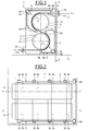
- a drying and ironing device referenced 1 as a whole, is intended for drying and ironing textile parts 2, such as, by way of non-limiting example, sheets, duvet covers formed by the superposition of two sheets, etc ...
- the drying and ironing device 1 comprises a casing 3, intended to be placed on the ground S, in which are mounted two cylinders 4, 5 or free rollers in rotation, hereinafter referred to as the upper cylinder and the lower cylinder.
- the cylinders 4, 5 are, for example, made of metallic material.
- the cylindrical surface 4a, 5a of the cylinders 4, 5 is provided with heating films 6, 7, for example of silicone-type material, of elastomeric material and comprising a plurality of electrical resistors powered by rotating contactors (not shown).
- the heating films 6, 7 form the means for heating the cylinders 4, 5.
- the use of a network of electrical resistors powered by rotating contactors makes it possible to overcome the drawbacks related to the inertia of the metal rolls and consequently to adapt in real time the surface temperature of the rolls to the amount of textile pieces to be treated.
- only the surface films 6, 7 are heated, thereby reducing the energy consumption compared to the use of fully heated cylinders.
- the drying and ironing device 1 also comprises a conveying device 8, 9 of the textile parts 2 associated with each of the cylinders 4, 5.
- each of the conveying devices 8, 9 of the textile parts 2 comprises a plurality of endless driving belts 8a, 9a arranged in the same horizontal plane and made for example of felted material, a plurality of guide means 8b, 9b of each drive belt 8a, 9a and a plurality of drive rollers 8c, 9c rotated by a motor 8d, 9d mounted on a side wall of the housing 3.
- Each motor 8d, 9d is thus intended to set in motion a plurality of driving strips 8a, 9a via the associated driving roller 8c, 9c.
- the cylinders 4, 5, free in rotation about their axis X 1 -X 1 and X 2 -X 2 are rotated by the action of the textile parts 2, themselves driven by the drive bands 8a, 9a which play the role of transmission belts.
- the engine 8d of the conveying device 8 associated with the upper cylinder 4 rotates in a first direction of rotation F 1 and the motor 9d of the conveying device 9 associated with the lower cylinder 5 rotates in a second direction of rotation F 2 , opposite to the first direction of rotation F 1 .
- the upper cylinder 4 is rotated in the second direction of rotation F 2 and the lower cylinder 5 is rotated in the first direction of rotation F 1 .
- the casing 3 is provided with an inlet 3a of the textile parts 2 arranged upstream of the upper conveying device 8, so as to bring the textile parts 2 to the upper cylinder 4 and an outlet 3b of the textile parts 2 arranged downstream. of the device lower conveying 9, so as to bring the textile parts 2 from the lower cylinder 5 to the outside.
- an articulated flap 10 located near the inlet 3a of the housing 3 allows the guiding of the textile parts 2 between the inlet 3a of the housing 3 and the textile strip 8a associated with the upper cylinder 4. It could also be provided an articulated flap located near the outlet 3b of the casing 3 to guide textile pieces between the textile strip 9a associated with the lower cylinder 5 and the outlet 3b of the casing 3.
- Each of the inlet 3a and outlet 3b are provided with sealing means 11a, 11b, such as, for example, sealing lips.
- sealing means 11a, 11b such as, for example, sealing lips.
- the walls of the housing 3 are for this purpose made of waterproof material. In other words, the walls of the casing 3 are assembled together in a sealed manner.
- the drying and ironing device 1 comprises a means for creating a vacuum (not shown), such as for example a vacuum pump to create a vacuum inside the casing 3.
- a vacuum such as for example a vacuum pump to create a vacuum inside the casing 3.
- the textile pieces 2 are thus introduced through the inlet 3a located at the front of the drying and ironing device 1 and then guided until contact with the driving strips 8a. Under the action of the upper drive bands 8a, the textile parts 2 are partially wound around the upper cylinder 4 and under the action of the lower drive bands 9a, the textile parts 2 are partially wound around the lower cylinder 5 to be guided to the outlet 3b at the rear of the drying and ironing device 1.
- the driving belts 8a of the upper conveying device 8 surround a portion of the upper roll 4 so as to form an inclined "U” path for the textile pieces to treat.
- the drive belts 9a of the lower conveying device 9 surround a portion of the lower cylinder 5 so as to form an inclined "U” path for the textile parts to be treated.
- the textile pieces 2 thus traverse an "S" -shaped path in which they come into contact with the heated surfaces 4a, 5a of the cylinders 4, 5 thus causing the evaporation of the water contained in the textile pieces 2, respectively by the heating of a first face of the textile piece by the upper roll 4 and then a second face of the textile piece by the lower roll 5.
- the ironing function of the textile pieces 2 is performed by the training strips 8a, 9a which come to press the textile parts 2 against the associated cylinder 4, 5.
- the spacing between the driving belts 8a of the upper conveying device 8 and the driving belts 9a of the lower conveying device 9 is defined so that the textile part 2 is guided from the upper roll 4 to the lower roll 5
- the lower part of the driving belts 8a of the upper conveying device 8 is on the same horizontal plane as the upper part of the driving belts 9a of the lower conveying device 9.
- the drying and ironing device 1 thus makes it possible to heat and thus dry a textile part 2 successively on both sides, which allows a homogeneous drying of the textile part 2.
- This is particularly advantageous for conventional items of linen such as sheets , but also for the thick duvet cover type parts formed generally by the combination of two sheets sewn together on their periphery or on most of their periphery.
- the arrangement of cylinders 4, 5 of small diameter one above the other allows to have the inlet 3a of the housing 3 at about 1m20 from the ground and thus improve the usability of the device In fact, this allows a comfortable working position for an operator standing in front of the drying and ironing device 1.
- the textile parts 2 exiting through the outlet 3b located at the rear of the casing 3 can be brought to an automatic folding device (not shown).
Landscapes
- Engineering & Computer Science (AREA)
- Textile Engineering (AREA)
- Treatment Of Fiber Materials (AREA)
Abstract
Description
- La présente invention concerne le domaine du traitement et notamment le séchage et le repassage de pièces textiles.
- Il existe des machines permettant de sécher et de repasser des pièces textiles comportant une pluralité de cylindres motorisés et agencés côte à côte sur un même plan horizontal, des bandes de transport destinées à transporter la pièce textile à traiter. Chaque cylindre est associé à une pièce concave chauffée et plaquée contre le cylindre afin de comprimer la pièce textile se trouvant entre un cylindre et sa pièce concave associée. Les pièces textiles ainsi transportées subissent à la fois un chauffage et un calandrage.
- De telles machines sont particulièrement encombrantes et ne permettent pas un chauffage uniforme des pièces textiles, notamment des housses de couettes présentant une double épaisseur de tissu.
- Le document
FR 2 415 163 - Le but de l'invention est donc de pallier ces inconvénients et de fournir un dispositif de séchage et repassage permettant le séchage homogène de la pièce textile à traiter, sans nécessiter de régler les paramètres de fonctionnement en fonction du type de pièce textile à traiter ou des conditions de température et d'humidité dans lesquelles se trouve le dispositif de séchage et repassage. L'invention a également pour objet de limiter la consommation énergétique tout en augmentant les performances en termes de productivité.
- Un autre objectif de l'invention est d'améliorer l'ergonomie et le confort d'utilisation de tels dispositifs de séchage et repassage.
- Dans un mode de réalisation, l'invention concerne un dispositif de séchage et repassage de pièces textiles comportant un carter dans lequel sont montés au moins deux cylindres dont les axes sont disposés dans un même plan vertical et un dispositif de convoyage des pièces textiles associé à chacun des cylindres. Lesdits cylindres sont montés libres en rotation par rapport à leur axe et comportent chacun sur leur surface cylindrique des moyens de chauffage.
- Ainsi, les pièces textiles parcourent un chemin en forme de « S » au cours duquel elles viennent en contact des surfaces chauffées des cylindres provoquant ainsi l'évaporation de l'eau contenue dans les pièces textiles d'une première face de la pièce textile par le cylindre supérieur puis d'une deuxième face de la pièce textile par le cylindre inférieur. On obtient donc un séchage homogène de la pièce textile.
- Avantageusement, la surface cylindrique des cylindres est munie de films chauffants comportant une pluralité de résistances électriques alimentées par des contacteurs tournants. Les films chauffants sont, par exemple, réalisés en silicone ou en matériau élastomère.
- Dans un mode de réalisation, le carter est étanche.
- En d'autres termes, les parois du carter sont agencées et assemblées entre elles de façon étanche.
- Le carter peut être muni d'une entrée des pièces textiles disposée en amont du dispositif de convoyage associé au cylindre supérieur et d'une sortie des pièces textiles disposée en aval du dispositif de convoyage associé au cylindre inférieur, chacune des entrée et sortie est pourvue de moyens d'étanchéité.
- Avantageusement, le dispositif de séchage et repassage comprend un moyen de création d'une dépression à l'intérieur du carter.
- Le moyen de création de vide à l'intérieur du carter étanche permet de réduire la température d'évaporation de l'eau contenue dans les pièces textiles. Le séchage des pièces textiles est donc plus rapide et nécessite une consommation énergétique plus faible.
- Dans un mode de réalisation, le dispositif de séchage et repassage comprend un volet articulé situé à proximité de l'entrée du carter pour guider les pièces textiles entre l'entrée du carter et la bande textile associée au cylindre supérieur.
- Chacun des dispositifs de convoyage des pièces textiles peut comprendre au moins une bande d'entrainement sans fin, une pluralité de moyens de guidages de la bande d'entrainement et au moins un galet d'entrainement entrainé en rotation par un moteur.
- Le moteur du dispositif de convoyage associé au cylindre supérieur tourne, par exemple, dans un premier sens de rotation F1 et le moteur du dispositif de convoyage associé au cylindre inférieur tourne, par exemple, dans un deuxième sens de rotation F2, opposé au premier sens de rotation F1.
- Dans un mode de réalisation, chacun des dispositifs de convoyage des pièces textiles comprend au moins deux bandes d'entrainement sans fin disposées dans un même plan horizontal.
- Les cylindres peuvent présenter chacun un diamètre inférieur ou égal à 500mm, par exemple compris entre 300mm et 500mm.
- D'autres avantages et caractéristiques apparaîtront à l'examen de la description détaillée de quelques modes de réalisation pris à titre d'exemples nullement limitatifs et illustrés par les dessins annexés, sur lesquels :
- la
figure 1 représente schématiquement une vue en coupe d'un dispositif de séchage et repassage selon l'invention, et - la
figure 2 illustre une vue selon la coupe II-II du dispositif de séchage et repassage de lafigure 1 . - Tel qu'illustré à la
figure 1 , un dispositif de séchage et repassage, référencé 1 dans son ensemble, est destiné à sécher et à repasser des pièces textiles 2, telles que, à titre d'exemple non limitatif, des draps, des housses de couettes formés par la superposition de deux draps, etc... - Le dispositif de séchage et repassage 1 comprend un carter 3, destiné à être posé sur le sol S, dans lequel sont montés deux cylindres 4, 5 ou rouleaux libres en rotation dénommés ci-après cylindre supérieur et cylindre inférieur. Les cylindres 4, 5, respectivement d'axe X1-X1 ; X2-X2, disposés dans un même plan vertical et présentent chacun un diamètre inférieur à 500mm, par exemple compris entre 300 et 500mm. Les cylindres 4, 5 sont, par exemple, réalisés en matériau métallique.
- Tel qu'illustré, la surface cylindrique 4a, 5a des cylindres 4, 5 est munie de films chauffants 6, 7, par exemple en matériau de type silicone, en matériau élastomère et comportant une pluralité de résistances électriques alimentées par des contacteurs tournants (non représentés). Les films chauffants 6, 7 forment les moyens de chauffage des cylindres 4, 5. L'utilisation d'un réseau de résistances électriques alimentées par des contacteurs tournants permet de s'affranchir des inconvénients liés à l'inertie des cylindres métalliques et par conséquent d'adapter en temps réel la température de surface des cylindres à la quantité de pièces textiles à traiter. De plus, seuls les films de surfaces 6, 7 sont chauffés, permettant ainsi de réduire la consommation énergétique par rapport à l'utilisation de cylindres chauffés entièrement.
- Le dispositif de séchage et repassage 1 comporte également un dispositif de convoyage 8, 9 des pièces textiles 2 associé à chacun des cylindres 4, 5.
- Tel qu'illustré sur la
figure 2 , chacun des dispositifs de convoyage 8, 9 des pièces textiles 2 comprend une pluralité de bandes d'entrainement sans fin 8a, 9a disposées dans un même plan horizontal et réalisées par exemple en matériau feutré, une pluralité de moyens de guidages 8b, 9b de chaque bande d'entrainement 8a, 9a et une pluralité de galets d'entrainement 8c, 9c entrainés en rotation par un moteur 8d, 9d monté sur une paroi latérale du carter 3. - Chaque moteur 8d, 9d est ainsi destiné à mettre en mouvement une pluralité de bandes d'entrainement 8a, 9a par l'intermédiaire du galet d'entrainement associé 8c, 9c. Les cylindres 4, 5, libres en rotation autour de leur axe X1-X1 et X2-X2, sont mis en rotation par l'action des pièces textiles 2, elles-mêmes entrainées par les bandes d'entrainement 8a, 9a qui jouent le rôle de courroies de transmission.
- Le moteur 8d du dispositif de convoyage 8 associé au cylindre supérieur 4 tourne dans un premier sens de rotation F1 et le moteur 9d du dispositif de convoyage 9 associé au cylindre inférieur 5 tourne dans un deuxième sens de rotation F2, opposé au premier sens de rotation F1. Ainsi, le cylindre supérieur 4 est entrainé en rotation dans le deuxième sens de rotation F2 et le cylindre inférieur 5 est entrainé en rotation dans le premier sens de rotation F1.
- Dans l'exemple illustré, les bandes d'entrainement 8a, 9a sont au nombre de quatre par dispositif de convoyage 8, 9. On notera que l'on pourrait prévoir un nombre de bande d'entrainement supérieur ou égal à un, auquel cas on pourrait prévoir une bande d'entrainement plus large afin d'entrainer la pièce textile 2 à traiter.
- Le carter 3 est muni d'une entrée 3a des pièces textiles 2 disposée en amont du dispositif de convoyage supérieur 8, de manière à amener les pièces textiles 2 vers le cylindre supérieur 4 et d'une sortie 3b des pièces textiles 2 disposée en aval du dispositif de convoyage inférieur 9, de manière à amener les pièces textiles 2 depuis le cylindre inférieur 5 vers l'extérieur. Tel qu'illustré, un volet articulé 10 situé à proximité de l'entrée 3a du carter 3 permet le guidage des pièces textiles 2 entre l'entrée 3a du carter 3 et la bande textile 8a associée au cylindre supérieur 4. On pourrait également prévoir un volet articulé situé à proximité de la sortie 3b du carter 3 afin de guider des pièces textiles entre la bande textile 9a associée au cylindre inférieure 5 et la sortie 3b du carter 3.
- Chacune des entrée 3a et sortie 3b sont pourvues de moyens d'étanchéité 11a, 11b, tel que par exemple des lèvres d'étanchéité. En variante, on pourrait prévoir des clapets ou tout autre moyen permettant d'assurer l'étanchéité du carter 3. Les parois du carter 3 sont à cet effet réalisées en matériau étanche. En d'autres termes, les parois du carter 3 sont assemblées entre elles de façon étanche.
- Le dispositif de séchage et repassage 1 comporte un moyen de création d'une dépression (non représenté), tel que par exemple une pompe à vide afin de créer une dépression à l'intérieur du carter 3. Ainsi, la température d'évaporation de l'eau contenue dans les pièces textiles 2 peut être abaissée, ce qui permet d'obtenir le séchage des pièces textiles 2 tout en limitant la consommation énergétique.
- Les pièces textiles 2 sont donc introduites par l'entrée 3a se trouvant à l'avant du dispositif de séchage et repassage 1 puis sont guidées jusqu'au contact des bandes d'entrainement 8a. Sous l'action des bandes d'entrainement supérieures 8a, les pièces textiles 2 s'enroulent partiellement autour du cylindre supérieur 4 puis sous l'action des bandes d'entrainement inférieures 9a, les pièces textiles 2 s'enroulent partiellement autour du cylindre inférieur 5 afin d'être guidées vers la sortie 3b se trouvant à l'arrière du dispositif de séchage et repassage 1.
- Les bandes d'entrainement 8a du dispositif de convoyage supérieur 8 viennent entourer une partie du cylindre supérieur 4 de manière à former un chemin en « U » incliné pour les pièces textiles à traiter. De manière similaire, les bandes d'entrainement 9a du dispositif de convoyage inférieur 9 viennent entourer une partie du cylindre inférieur 5 de manière à former un chemin en « U » incliné pour les pièces textiles à traiter.
- Les pièces textiles 2 parcourent ainsi un chemin en forme de « S » au cours duquel elles viennent en contact des surfaces chauffées 4a, 5a des cylindres 4, 5 provoquant ainsi l'évaporation de l'eau contenue dans les pièces textiles 2, respectivement par le chauffage d'une première face de la pièce textile par le cylindre supérieur 4 puis d'une deuxième face de la pièce textile par le cylindre inférieur 5. La fonction repassage des pièces textiles 2 est réalisée par les bandes d'entrainement 8a, 9a qui viennent plaquer les pièces textiles 2 contre le cylindre associé 4, 5.
- L'écartement entre les bandes d'entrainement 8a du dispositif de convoyage supérieur 8 et les bandes d'entrainement 9a du dispositif de convoyage inférieur 9 est défini de telle sorte que la pièce textile 2 est guidée du cylindre supérieur 4 vers le cylindre inférieur 5. Tel qu'illustré, la partie inférieure des bandes d'entrainement 8a du dispositif de convoyage supérieur 8 se trouve sur un même plan horizontal que la partie supérieure des bandes d'entrainement 9a du dispositif de convoyage inférieur 9.
- Le dispositif de séchage et repassage 1 permet ainsi de chauffer et donc sécher une pièce textile 2 successivement sur ses deux faces, ce qui permet un séchage homogène de la pièce textile 2. Ceci est particulièrement intéressant pour les pièces de linge classiques telles que les draps, mais également pour les pièces épaisses de type housse de couettes formées généralement par la combinaison de deux draps cousus entre eux sur leur périphérie ou sur la plus grande partie de leur périphérie.
- La disposition des cylindres 4, 5 de faible diamètre l'un au-dessus de l'autre permet de disposer l'entrée 3a du carter 3 à environ 1m20 du sol et ainsi améliorer l'ergonomie d'utilisation du dispositif de séchage et repassage 1. En effet, ceci permet une position de travail confortable pour un opérateur en position debout devant le dispositif de séchage et repassage 1. De plus les pièces textiles 2 sortant par la sortie 3b se trouvant à l'arrière du carter 3 peuvent être amenées à un dispositif de pliage automatique (non représenté).
- Grace à l'invention, il est possible de sécher de manière uniforme une pièce textile, et notamment les pièces textiles présentant une double épaisseur de tissu telles que les housses de couettes, tout en réduisant l'encombrement et la consommation énergétique.
- De plus, l'utilisation d'un tel dispositif de séchage et repassage se trouve particulièrement aisé grâce à la superposition axiale dans un même plan vertical des cylindres de faible diamètre.
Claims (10)
- Dispositif de séchage et repassage de pièces textiles (2) comportant un carter (3) dans lequel sont montés au moins deux cylindres (4, 5) dont les axes de rotation (X1-X1, X2-X2) sont disposés dans un même plan vertical et un dispositif de convoyage (8, 9) des pièces textiles (2) associé à chacun des cylindres (4, 5), lesdits cylindres (4, 5) sont montés libres en rotation par rapport à leur axe (X1-X1 et X2-X2) et comportent chacun sur leur surface cylindrique extérieure (4a, 5a) des films chauffants (6, 7) comportant une pluralité de résistances électriques alimentées par des contacteurs tournants.
- Dispositif de séchage et repassage selon la revendication 1, dans lequel les films chauffants (6, 7) sont réalisés en silicone ou en matériau élastomère.
- Dispositif de séchage et repassage selon l'une quelconque des revendications précédentes, dans lequel le carter (3) est étanche.
- Dispositif de séchage et repassage selon la revendication 3, dans lequel le carter (3) est muni d'une entrée (3a) des pièces textiles (2) disposée en amont du dispositif de convoyage (8) associé au cylindre supérieur (4) et d'une sortie (3b) des pièces textiles (2) disposée en aval du dispositif de convoyage (9) associé au cylindre inférieur (5), chacune des entrée et sortie (3a, 3b) est pourvue de moyens d'étanchéité (11a, 11b).
- Dispositif de séchage et repassage selon les revendications 3 et 4, comprenant un moyen de création d'une dépression à l'intérieur du carter (3).
- Dispositif de séchage et repassage selon la revendication 4 ou 5, comprenant un volet articulé (10) situé à proximité de l'entrée (3a) du carter (3) pour guider les pièces textiles (2) entre l'entrée (3a) du carter (3) et le dispositif de convoyage (8) associé au cylindre supérieur (4).
- Dispositif de séchage et repassage selon l'une quelconque des revendications précédentes, dans lequel chacun des dispositifs de convoyage (8, 9) des pièces textiles (2) comprend au moins une bande d'entrainement sans fin (8a, 9a), une pluralité de moyens de guidage (8b, 9b) de la bande d'entrainement (8a, 9a) et au moins un galet d'entrainement (8c, 9c) entrainé en rotation par un moteur (8d, 9d).
- Dispositif de séchage et repassage selon la revendication 7, dans lequel le moteur (8d) du dispositif de convoyage (8) associé au cylindre supérieur (4) tourne dans un premier sens de rotation (F1) et le moteur (9d) du dispositif de convoyage (9) associé au cylindre inférieur (5) tourne dans un deuxième sens de rotation (F2), opposé au premier sens de rotation (F1).
- Dispositif de séchage et repassage selon la revendication 7 ou 8, dans lequel chacun des dispositifs de convoyage (8, 9) des pièces textiles (2) comprend au moins deux bandes d'entrainement sans fin (8a, 9a) disposées dans un même plan horizontal.
- Dispositif de séchage et repassage selon l'une quelconque des revendications précédentes, dans lequel les cylindres (4, 5) présentent chacun un diamètre inférieur ou égal à 500mm.
Applications Claiming Priority (1)
| Application Number | Priority Date | Filing Date | Title |
|---|---|---|---|
| FR1360914A FR3012822B1 (fr) | 2013-11-07 | 2013-11-07 | Dispositif de sechage et de repassage de pieces textiles |
Publications (2)
| Publication Number | Publication Date |
|---|---|
| EP2871281A1 true EP2871281A1 (fr) | 2015-05-13 |
| EP2871281B1 EP2871281B1 (fr) | 2017-01-25 |
Family
ID=49998473
Family Applications (1)
| Application Number | Title | Priority Date | Filing Date |
|---|---|---|---|
| EP14191020.8A Active EP2871281B1 (fr) | 2013-11-07 | 2014-10-30 | Dispositif de séchage et de repassage de pièces textiles |
Country Status (2)
| Country | Link |
|---|---|
| EP (1) | EP2871281B1 (fr) |
| FR (1) | FR3012822B1 (fr) |
Cited By (1)
| Publication number | Priority date | Publication date | Assignee | Title |
|---|---|---|---|---|
| CN107034643A (zh) * | 2017-06-21 | 2017-08-11 | 冯斌斌 | 一种服装熨烫设备 |
Citations (7)
| Publication number | Priority date | Publication date | Assignee | Title |
|---|---|---|---|---|
| FR1385543A (fr) * | 1963-12-03 | 1965-01-15 | Sécheuse-repasseuse perfectionnée | |
| FR2415163A1 (fr) | 1978-01-24 | 1979-08-17 | Theiler Robert | Machine a repasser |
| GB2102842A (en) * | 1981-07-20 | 1983-02-09 | Textima Veb K | A heated trough calender |
| US5551175A (en) * | 1994-10-17 | 1996-09-03 | Neyman; Joseph H. | Removing lint from flatwork ironer temperature sensors |
| WO2000058553A2 (fr) * | 1999-03-29 | 2000-10-05 | Racster Nicholas J | Element chauffant, corps chauffable et procede de fabrication d'un tel corps |
| DE19929520A1 (de) * | 1999-06-28 | 2001-01-04 | Voith Paper Patent Gmbh | Beheizter Zylinder |
| DE102008042285A1 (de) * | 2008-09-23 | 2010-03-25 | Voith Patent Gmbh | Beheizbarer Zylinder zur Aufheizung einer Papier-, Karton-, Tissue- oder anderen Materialbahn |
Family Cites Families (2)
| Publication number | Priority date | Publication date | Assignee | Title |
|---|---|---|---|---|
| DE3324351A1 (de) * | 1983-07-06 | 1985-01-24 | Wilh. Cordes GmbH & Co, 4740 Oelde | Buegelmaschine, waeschemangel o. dgl. mit einem als hohlkoerper ausgebildeten, allseitig geschlossenen buegelkoerper |
| FR2800398B1 (fr) * | 1999-10-05 | 2002-03-08 | Danube Internat | Secheuse-repasseuse equipee d'un dispositif de regulation en fonction de la temperature et de l'humidite |
-
2013
- 2013-11-07 FR FR1360914A patent/FR3012822B1/fr active Active
-
2014
- 2014-10-30 EP EP14191020.8A patent/EP2871281B1/fr active Active
Patent Citations (7)
| Publication number | Priority date | Publication date | Assignee | Title |
|---|---|---|---|---|
| FR1385543A (fr) * | 1963-12-03 | 1965-01-15 | Sécheuse-repasseuse perfectionnée | |
| FR2415163A1 (fr) | 1978-01-24 | 1979-08-17 | Theiler Robert | Machine a repasser |
| GB2102842A (en) * | 1981-07-20 | 1983-02-09 | Textima Veb K | A heated trough calender |
| US5551175A (en) * | 1994-10-17 | 1996-09-03 | Neyman; Joseph H. | Removing lint from flatwork ironer temperature sensors |
| WO2000058553A2 (fr) * | 1999-03-29 | 2000-10-05 | Racster Nicholas J | Element chauffant, corps chauffable et procede de fabrication d'un tel corps |
| DE19929520A1 (de) * | 1999-06-28 | 2001-01-04 | Voith Paper Patent Gmbh | Beheizter Zylinder |
| DE102008042285A1 (de) * | 2008-09-23 | 2010-03-25 | Voith Patent Gmbh | Beheizbarer Zylinder zur Aufheizung einer Papier-, Karton-, Tissue- oder anderen Materialbahn |
Cited By (2)
| Publication number | Priority date | Publication date | Assignee | Title |
|---|---|---|---|---|
| CN107034643A (zh) * | 2017-06-21 | 2017-08-11 | 冯斌斌 | 一种服装熨烫设备 |
| CN107034643B (zh) * | 2017-06-21 | 2018-04-13 | 吉林省荣发服装服饰有限公司 | 一种服装熨烫设备 |
Also Published As
| Publication number | Publication date |
|---|---|
| EP2871281B1 (fr) | 2017-01-25 |
| FR3012822B1 (fr) | 2016-09-09 |
| FR3012822A1 (fr) | 2015-05-08 |
Similar Documents
| Publication | Publication Date | Title |
|---|---|---|
| FR2488629A1 (fr) | Presse a pincage prolonge | |
| EP2871281B1 (fr) | Dispositif de séchage et de repassage de pièces textiles | |
| EP3467179B1 (fr) | Mécanisme de retournement | |
| FR2642334A1 (fr) | Appareil de nettoyage de tapis, notamment de tapis de sport a structure epaisse | |
| EP1367166A1 (fr) | Chariot mobile d'entrée d'étaleur-nappeur et étaleur-nappeur équipé dudit chariot | |
| FR2510627A1 (fr) | Dispositif pour le sechage et le repassage de linge humide | |
| EP0122835B1 (fr) | Procédé et dispositif de maintien d'un article textile en cours de traitement | |
| EP2883444A1 (fr) | Dispositif d'effeuillage double flux | |
| FR2905286A1 (fr) | Procede et dispositif de traitement physique et/ou chimique de produits en vrac au moyen d'un fluide gazeux. | |
| FR2486973A1 (fr) | Perfectionnements apportes aux machines a fouler et a laver les tissus | |
| FR2514794A1 (fr) | Perfectionnements aux secheuses-repasseuses | |
| EP0364386A1 (fr) | Machine pour le traitement fluidodynamique continu de matières filiformes groupées | |
| FR2656290A1 (fr) | Dispositif de separation et d'evacuation de chutes decoupees dans une bande de materiau. | |
| EP0165888A1 (fr) | Dispositif pour étirer positivement des pâtons pour la fabrication industrielle de pains longs | |
| FR2824082A1 (fr) | Machine pour la fabrication d'un non-tisse par voie aeraulique, comportant une chambre de dispersion des fibres la paroi avant est poreuse en partie basse | |
| FR2971046A1 (fr) | Installation de sechage de produits | |
| FR2509761A1 (fr) | Dispositif pour repasser et secher du linge humide | |
| FR2580946A1 (fr) | Presse a bandes filtrantes | |
| BE508275A (fr) | ||
| FR2760602A1 (fr) | Secheur centrifuge pour produits alimentaires vegetaux et procede de sechage | |
| FR2511897A1 (fr) | Dispositif pour l'application de substances visqueuses sur un materiel en bande en mouvement | |
| FR2478048A3 (fr) | Procede et appareil pour plier une ou plusieurs fois et traiter ensuite des textiles allonges | |
| FR2885769A1 (fr) | Machine de traitement de fromages | |
| BE1003517A3 (fr) | Calandre de repassage. | |
| FR3151585A1 (fr) | Ecluse d’air rotative et installation la comportant |
Legal Events
| Date | Code | Title | Description |
|---|---|---|---|
| PUAI | Public reference made under article 153(3) epc to a published international application that has entered the european phase |
Free format text: ORIGINAL CODE: 0009012 |
|
| 17P | Request for examination filed |
Effective date: 20141030 |
|
| AK | Designated contracting states |
Kind code of ref document: A1 Designated state(s): AL AT BE BG CH CY CZ DE DK EE ES FI FR GB GR HR HU IE IS IT LI LT LU LV MC MK MT NL NO PL PT RO RS SE SI SK SM TR |
|
| AX | Request for extension of the european patent |
Extension state: BA ME |
|
| R17P | Request for examination filed (corrected) |
Effective date: 20151102 |
|
| 17Q | First examination report despatched |
Effective date: 20160311 |
|
| GRAP | Despatch of communication of intention to grant a patent |
Free format text: ORIGINAL CODE: EPIDOSNIGR1 |
|
| INTG | Intention to grant announced |
Effective date: 20160906 |
|
| GRAS | Grant fee paid |
Free format text: ORIGINAL CODE: EPIDOSNIGR3 |
|
| GRAA | (expected) grant |
Free format text: ORIGINAL CODE: 0009210 |
|
| AK | Designated contracting states |
Kind code of ref document: B1 Designated state(s): AL AT BE BG CH CY CZ DE DK EE ES FI FR GB GR HR HU IE IS IT LI LT LU LV MC MK MT NL NO PL PT RO RS SE SI SK SM TR |
|
| REG | Reference to a national code |
Ref country code: GB Ref legal event code: FG4D Free format text: NOT ENGLISH |
|
| REG | Reference to a national code |
Ref country code: CH Ref legal event code: EP |
|
| REG | Reference to a national code |
Ref country code: AT Ref legal event code: REF Ref document number: 864214 Country of ref document: AT Kind code of ref document: T Effective date: 20170215 |
|
| REG | Reference to a national code |
Ref country code: IE Ref legal event code: FG4D Free format text: LANGUAGE OF EP DOCUMENT: FRENCH |
|
| REG | Reference to a national code |
Ref country code: DE Ref legal event code: R096 Ref document number: 602014006329 Country of ref document: DE |
|
| REG | Reference to a national code |
Ref country code: LT Ref legal event code: MG4D |
|
| REG | Reference to a national code |
Ref country code: NL Ref legal event code: MP Effective date: 20170125 |
|
| REG | Reference to a national code |
Ref country code: AT Ref legal event code: MK05 Ref document number: 864214 Country of ref document: AT Kind code of ref document: T Effective date: 20170125 |
|
| PG25 | Lapsed in a contracting state [announced via postgrant information from national office to epo] |
Ref country code: NL Free format text: LAPSE BECAUSE OF FAILURE TO SUBMIT A TRANSLATION OF THE DESCRIPTION OR TO PAY THE FEE WITHIN THE PRESCRIBED TIME-LIMIT Effective date: 20170125 |
|
| REG | Reference to a national code |
Ref country code: FR Ref legal event code: PLFP Year of fee payment: 4 |
|
| PG25 | Lapsed in a contracting state [announced via postgrant information from national office to epo] |
Ref country code: IS Free format text: LAPSE BECAUSE OF FAILURE TO SUBMIT A TRANSLATION OF THE DESCRIPTION OR TO PAY THE FEE WITHIN THE PRESCRIBED TIME-LIMIT Effective date: 20170525 Ref country code: LT Free format text: LAPSE BECAUSE OF FAILURE TO SUBMIT A TRANSLATION OF THE DESCRIPTION OR TO PAY THE FEE WITHIN THE PRESCRIBED TIME-LIMIT Effective date: 20170125 Ref country code: HR Free format text: LAPSE BECAUSE OF FAILURE TO SUBMIT A TRANSLATION OF THE DESCRIPTION OR TO PAY THE FEE WITHIN THE PRESCRIBED TIME-LIMIT Effective date: 20170125 Ref country code: GR Free format text: LAPSE BECAUSE OF FAILURE TO SUBMIT A TRANSLATION OF THE DESCRIPTION OR TO PAY THE FEE WITHIN THE PRESCRIBED TIME-LIMIT Effective date: 20170426 Ref country code: NO Free format text: LAPSE BECAUSE OF FAILURE TO SUBMIT A TRANSLATION OF THE DESCRIPTION OR TO PAY THE FEE WITHIN THE PRESCRIBED TIME-LIMIT Effective date: 20170425 Ref country code: FI Free format text: LAPSE BECAUSE OF FAILURE TO SUBMIT A TRANSLATION OF THE DESCRIPTION OR TO PAY THE FEE WITHIN THE PRESCRIBED TIME-LIMIT Effective date: 20170125 |
|
| PG25 | Lapsed in a contracting state [announced via postgrant information from national office to epo] |
Ref country code: LV Free format text: LAPSE BECAUSE OF FAILURE TO SUBMIT A TRANSLATION OF THE DESCRIPTION OR TO PAY THE FEE WITHIN THE PRESCRIBED TIME-LIMIT Effective date: 20170125 Ref country code: RS Free format text: LAPSE BECAUSE OF FAILURE TO SUBMIT A TRANSLATION OF THE DESCRIPTION OR TO PAY THE FEE WITHIN THE PRESCRIBED TIME-LIMIT Effective date: 20170125 Ref country code: ES Free format text: LAPSE BECAUSE OF FAILURE TO SUBMIT A TRANSLATION OF THE DESCRIPTION OR TO PAY THE FEE WITHIN THE PRESCRIBED TIME-LIMIT Effective date: 20170125 Ref country code: BG Free format text: LAPSE BECAUSE OF FAILURE TO SUBMIT A TRANSLATION OF THE DESCRIPTION OR TO PAY THE FEE WITHIN THE PRESCRIBED TIME-LIMIT Effective date: 20170425 Ref country code: PL Free format text: LAPSE BECAUSE OF FAILURE TO SUBMIT A TRANSLATION OF THE DESCRIPTION OR TO PAY THE FEE WITHIN THE PRESCRIBED TIME-LIMIT Effective date: 20170125 Ref country code: PT Free format text: LAPSE BECAUSE OF FAILURE TO SUBMIT A TRANSLATION OF THE DESCRIPTION OR TO PAY THE FEE WITHIN THE PRESCRIBED TIME-LIMIT Effective date: 20170525 Ref country code: SE Free format text: LAPSE BECAUSE OF FAILURE TO SUBMIT A TRANSLATION OF THE DESCRIPTION OR TO PAY THE FEE WITHIN THE PRESCRIBED TIME-LIMIT Effective date: 20170125 Ref country code: AT Free format text: LAPSE BECAUSE OF FAILURE TO SUBMIT A TRANSLATION OF THE DESCRIPTION OR TO PAY THE FEE WITHIN THE PRESCRIBED TIME-LIMIT Effective date: 20170125 |
|
| REG | Reference to a national code |
Ref country code: DE Ref legal event code: R097 Ref document number: 602014006329 Country of ref document: DE |
|
| PG25 | Lapsed in a contracting state [announced via postgrant information from national office to epo] |
Ref country code: IT Free format text: LAPSE BECAUSE OF FAILURE TO SUBMIT A TRANSLATION OF THE DESCRIPTION OR TO PAY THE FEE WITHIN THE PRESCRIBED TIME-LIMIT Effective date: 20170125 Ref country code: EE Free format text: LAPSE BECAUSE OF FAILURE TO SUBMIT A TRANSLATION OF THE DESCRIPTION OR TO PAY THE FEE WITHIN THE PRESCRIBED TIME-LIMIT Effective date: 20170125 Ref country code: SK Free format text: LAPSE BECAUSE OF FAILURE TO SUBMIT A TRANSLATION OF THE DESCRIPTION OR TO PAY THE FEE WITHIN THE PRESCRIBED TIME-LIMIT Effective date: 20170125 Ref country code: RO Free format text: LAPSE BECAUSE OF FAILURE TO SUBMIT A TRANSLATION OF THE DESCRIPTION OR TO PAY THE FEE WITHIN THE PRESCRIBED TIME-LIMIT Effective date: 20170125 Ref country code: CZ Free format text: LAPSE BECAUSE OF FAILURE TO SUBMIT A TRANSLATION OF THE DESCRIPTION OR TO PAY THE FEE WITHIN THE PRESCRIBED TIME-LIMIT Effective date: 20170125 |
|
| PG25 | Lapsed in a contracting state [announced via postgrant information from national office to epo] |
Ref country code: DK Free format text: LAPSE BECAUSE OF FAILURE TO SUBMIT A TRANSLATION OF THE DESCRIPTION OR TO PAY THE FEE WITHIN THE PRESCRIBED TIME-LIMIT Effective date: 20170125 Ref country code: SM Free format text: LAPSE BECAUSE OF FAILURE TO SUBMIT A TRANSLATION OF THE DESCRIPTION OR TO PAY THE FEE WITHIN THE PRESCRIBED TIME-LIMIT Effective date: 20170125 |
|
| PLBE | No opposition filed within time limit |
Free format text: ORIGINAL CODE: 0009261 |
|
| STAA | Information on the status of an ep patent application or granted ep patent |
Free format text: STATUS: NO OPPOSITION FILED WITHIN TIME LIMIT |
|
| 26N | No opposition filed |
Effective date: 20171026 |
|
| PG25 | Lapsed in a contracting state [announced via postgrant information from national office to epo] |
Ref country code: SI Free format text: LAPSE BECAUSE OF FAILURE TO SUBMIT A TRANSLATION OF THE DESCRIPTION OR TO PAY THE FEE WITHIN THE PRESCRIBED TIME-LIMIT Effective date: 20170125 |
|
| REG | Reference to a national code |
Ref country code: DE Ref legal event code: R119 Ref document number: 602014006329 Country of ref document: DE |
|
| PG25 | Lapsed in a contracting state [announced via postgrant information from national office to epo] |
Ref country code: MC Free format text: LAPSE BECAUSE OF FAILURE TO SUBMIT A TRANSLATION OF THE DESCRIPTION OR TO PAY THE FEE WITHIN THE PRESCRIBED TIME-LIMIT Effective date: 20170125 |
|
| REG | Reference to a national code |
Ref country code: CH Ref legal event code: PL |
|
| REG | Reference to a national code |
Ref country code: IE Ref legal event code: MM4A |
|
| REG | Reference to a national code |
Ref country code: FR Ref legal event code: PLFP Year of fee payment: 5 |
|
| PG25 | Lapsed in a contracting state [announced via postgrant information from national office to epo] |
Ref country code: DE Free format text: LAPSE BECAUSE OF NON-PAYMENT OF DUE FEES Effective date: 20180501 Ref country code: LI Free format text: LAPSE BECAUSE OF NON-PAYMENT OF DUE FEES Effective date: 20171031 Ref country code: LU Free format text: LAPSE BECAUSE OF NON-PAYMENT OF DUE FEES Effective date: 20171030 Ref country code: CH Free format text: LAPSE BECAUSE OF NON-PAYMENT OF DUE FEES Effective date: 20171031 |
|
| REG | Reference to a national code |
Ref country code: BE Ref legal event code: MM Effective date: 20171031 |
|
| PG25 | Lapsed in a contracting state [announced via postgrant information from national office to epo] |
Ref country code: BE Free format text: LAPSE BECAUSE OF NON-PAYMENT OF DUE FEES Effective date: 20171031 |
|
| PG25 | Lapsed in a contracting state [announced via postgrant information from national office to epo] |
Ref country code: MT Free format text: LAPSE BECAUSE OF FAILURE TO SUBMIT A TRANSLATION OF THE DESCRIPTION OR TO PAY THE FEE WITHIN THE PRESCRIBED TIME-LIMIT Effective date: 20170125 |
|
| PG25 | Lapsed in a contracting state [announced via postgrant information from national office to epo] |
Ref country code: IE Free format text: LAPSE BECAUSE OF NON-PAYMENT OF DUE FEES Effective date: 20171030 |
|
| GBPC | Gb: european patent ceased through non-payment of renewal fee |
Effective date: 20181030 |
|
| PG25 | Lapsed in a contracting state [announced via postgrant information from national office to epo] |
Ref country code: HU Free format text: LAPSE BECAUSE OF FAILURE TO SUBMIT A TRANSLATION OF THE DESCRIPTION OR TO PAY THE FEE WITHIN THE PRESCRIBED TIME-LIMIT; INVALID AB INITIO Effective date: 20141030 |
|
| PG25 | Lapsed in a contracting state [announced via postgrant information from national office to epo] |
Ref country code: CY Free format text: LAPSE BECAUSE OF FAILURE TO SUBMIT A TRANSLATION OF THE DESCRIPTION OR TO PAY THE FEE WITHIN THE PRESCRIBED TIME-LIMIT Effective date: 20170125 Ref country code: GB Free format text: LAPSE BECAUSE OF NON-PAYMENT OF DUE FEES Effective date: 20181030 |
|
| PG25 | Lapsed in a contracting state [announced via postgrant information from national office to epo] |
Ref country code: MK Free format text: LAPSE BECAUSE OF FAILURE TO SUBMIT A TRANSLATION OF THE DESCRIPTION OR TO PAY THE FEE WITHIN THE PRESCRIBED TIME-LIMIT Effective date: 20170125 |
|
| PG25 | Lapsed in a contracting state [announced via postgrant information from national office to epo] |
Ref country code: TR Free format text: LAPSE BECAUSE OF FAILURE TO SUBMIT A TRANSLATION OF THE DESCRIPTION OR TO PAY THE FEE WITHIN THE PRESCRIBED TIME-LIMIT Effective date: 20170125 |
|
| PG25 | Lapsed in a contracting state [announced via postgrant information from national office to epo] |
Ref country code: AL Free format text: LAPSE BECAUSE OF FAILURE TO SUBMIT A TRANSLATION OF THE DESCRIPTION OR TO PAY THE FEE WITHIN THE PRESCRIBED TIME-LIMIT Effective date: 20170125 |
|
| PGFP | Annual fee paid to national office [announced via postgrant information from national office to epo] |
Ref country code: FR Payment date: 20251028 Year of fee payment: 12 |