EP2871307B2 - Réserve de marche pour un verrou motorisé - Google Patents
Réserve de marche pour un verrou motorisé Download PDFInfo
- Publication number
- EP2871307B2 EP2871307B2 EP14191762.5A EP14191762A EP2871307B2 EP 2871307 B2 EP2871307 B2 EP 2871307B2 EP 14191762 A EP14191762 A EP 14191762A EP 2871307 B2 EP2871307 B2 EP 2871307B2
- Authority
- EP
- European Patent Office
- Prior art keywords
- lock
- motor
- energy
- slide
- voltage
- Prior art date
- Legal status (The legal status is an assumption and is not a legal conclusion. Google has not performed a legal analysis and makes no representation as to the accuracy of the status listed.)
- Active
Links
Images

Classifications
-
- E—FIXED CONSTRUCTIONS
- E05—LOCKS; KEYS; WINDOW OR DOOR FITTINGS; SAFES
- E05B—LOCKS; ACCESSORIES THEREFOR; HANDCUFFS
- E05B47/00—Operating or controlling locks or other fastening devices by electric or magnetic means
- E05B47/02—Movement of the bolt by electromagnetic means; Adaptation of locks, latches, or parts thereof, for movement of the bolt by electromagnetic means
- E05B47/026—Movement of the bolt by electromagnetic means; Adaptation of locks, latches, or parts thereof, for movement of the bolt by electromagnetic means the bolt moving rectilinearly
-
- E—FIXED CONSTRUCTIONS
- E05—LOCKS; KEYS; WINDOW OR DOOR FITTINGS; SAFES
- E05B—LOCKS; ACCESSORIES THEREFOR; HANDCUFFS
- E05B47/00—Operating or controlling locks or other fastening devices by electric or magnetic means
- E05B47/0001—Operating or controlling locks or other fastening devices by electric or magnetic means with electric actuators; Constructional features thereof
- E05B47/0012—Operating or controlling locks or other fastening devices by electric or magnetic means with electric actuators; Constructional features thereof with rotary electromotors
-
- E—FIXED CONSTRUCTIONS
- E05—LOCKS; KEYS; WINDOW OR DOOR FITTINGS; SAFES
- E05B—LOCKS; ACCESSORIES THEREFOR; HANDCUFFS
- E05B59/00—Locks with latches separate from the lock-bolts or with a plurality of latches or lock-bolts
-
- E—FIXED CONSTRUCTIONS
- E05—LOCKS; KEYS; WINDOW OR DOOR FITTINGS; SAFES
- E05B—LOCKS; ACCESSORIES THEREFOR; HANDCUFFS
- E05B65/00—Locks or fastenings for special use
- E05B65/10—Locks or fastenings for special use for panic or emergency doors
- E05B65/108—Electronically controlled emergency exits
-
- E—FIXED CONSTRUCTIONS
- E05—LOCKS; KEYS; WINDOW OR DOOR FITTINGS; SAFES
- E05B—LOCKS; ACCESSORIES THEREFOR; HANDCUFFS
- E05B47/00—Operating or controlling locks or other fastening devices by electric or magnetic means
- E05B47/0001—Operating or controlling locks or other fastening devices by electric or magnetic means with electric actuators; Constructional features thereof
- E05B2047/0014—Constructional features of actuators or power transmissions therefor
- E05B2047/0018—Details of actuator transmissions
- E05B2047/0024—Cams
-
- E—FIXED CONSTRUCTIONS
- E05—LOCKS; KEYS; WINDOW OR DOOR FITTINGS; SAFES
- E05B—LOCKS; ACCESSORIES THEREFOR; HANDCUFFS
- E05B47/00—Operating or controlling locks or other fastening devices by electric or magnetic means
- E05B2047/0048—Circuits, feeding, monitoring
- E05B2047/0057—Feeding
-
- E—FIXED CONSTRUCTIONS
- E05—LOCKS; KEYS; WINDOW OR DOOR FITTINGS; SAFES
- E05B—LOCKS; ACCESSORIES THEREFOR; HANDCUFFS
- E05B47/00—Operating or controlling locks or other fastening devices by electric or magnetic means
- E05B2047/0084—Key or electric means; Emergency release
- E05B2047/0086—Emergency release, e.g. key or electromagnet
- E05B2047/0087—Electric spare devices, e.g. auxiliary batteries or capacitors for back up
Definitions
- the present invention relates to a motor-operated lock and a device for a door for the electrical supply of the motor-operated lock according to the preamble of claim 1, the lock having a lock housing, a lock latch movable between a locked position and an unlocked position, a translationally movably mounted slide and a locking mechanism has (includes), on which the slide acts and thereby releases the latch. Furthermore, the lock has a motor-gear unit for moving the slide via an engagement device.
- Such door locks are widely known. In other words, there are a large number of slide-controlled door locks on the market. With these door locks, the processes in the door lock are "controlled” via a slide. In such door locks, the movably mounted slide is moved via a motor-gear unit. This means that the motor-gear unit is responsible for unlocking the door lock by lifting the slide. Examples of locking devices with a motorized drive device for actuating the bolt of a lock can be found in EP 2 016 243 B1 and EP 1 203 860 A1 .
- the known door locks have a slider mounted so as to be movable in translation.
- the slide is advantageously movably mounted in the lock housing of the door lock.
- the slide is in operative connection with a latch of the door lock.
- the latch of the door lock can be moved between a locked position and an unlocked position.
- the lock latch which can in particular be designed as a cross latch, protrudes from the door lock, in particular the lock housing, so as to engage in a lock latch receptacle of a door frame.
- the unlocked position the lock latch is pulled into the door lock or the lock housing to release the door.
- the latch can be pivoted between the two positions.
- the lock latch is preferably mounted such that it can move linearly between the locked position and the unlocked position.
- the operative connection between the slide and the lock latch is established by the locking mechanism, also referred to as the hinge mechanism, of the door lock.
- the locking mechanism locks the latch.
- the locking of the locking mechanism is released by a translatory movement of the slide.
- the latch is only moved by pressing the door open.
- the additional latch head is only moved by pushing the door open. However, at no point does the lock of the additional latch head lock.
- the slide is taken along by an engagement device, for example by a mandrel which is located on a worm wheel of the motor-gear unit and which hits the slide when the worm wheel rotates, whereby the slide within the door lock or .
- an engagement device for example by a mandrel which is located on a worm wheel of the motor-gear unit and which hits the slide when the worm wheel rotates, whereby the slide within the door lock or .
- An engagement element arranged on a drive wheel is also known as an engagement device, the drive wheel being driven by the motor-gear unit.
- the engagement device is arranged eccentrically to the axis of rotation of the drive wheel and is designed such that when the drive wheel rotates, the engagement element causes the slide to be displaced via a slide contact surface, i.e. H. by contacting the slide contact surface. When the slide is displaced, the contact contour of the engagement element slides along the slide contact surface.
- the engagement element comes into contact with the slide when the drive wheel rotates and takes it with it when it rotates.
- the slide is thereby moved within the door lock or the lock housing, in particular displaced linearly.
- the drive wheel with the engagement element arranged thereon is preferably rotated further clockwise, the engagement element comes out of contact with the slide, i. H. into an out of contact position with the slide.
- the lock latch can act on the locking mechanism, which leads to a movement of the slide, whereby the bolt can in turn be moved into its locking position.
- the motor-gear unit in particular the motor, which is used to drive the drive wheel rotatably mounted about the axis of rotation with the engagement element arranged on it or which is used to drive the mandrel, which for example is arranged on a worm wheel of the motor-gear unit, is no longer energetically supplied, this can be in a certain position of the engagement element or the mandrel relative to the slide, namely when the engagement element or the mandrel is in a contact position with the slide , to a blockage of the slide, ie to an inhibition of the translational movement of the slide.
- the force determined for actuating the locking mechanism cannot be transmitted from or to the slide, so that locking, for example a panic or fire protection door, is no longer guaranteed is, in particular the bolt coupled to the slide cannot be moved into its locking position. Also, a contact position of the engagement element or the mandrel with the slide must not result in a locked panic or fire protection door no longer opening the panic or escape route.
- the engagement element and the mandrel are to be understood as the engagement device.
- the invention includes the technical teaching that an energy-storing element can be integrated into the lock housing, and that the energy-storing element can be connected to a voltage source, and wherein the energy-storing element is designed at least so that in the event of a power failure or power interruption the motor is electrically operable to move the engagement device out of contact with the slide.
- the device according to the invention should therefore also be understood as a power reserve.
- the energy in the energy-storing element takes place essentially through electrostatic energy storage, the energy storage having at least an energy density of 1J / cm 3 .
- 1J 1Ws. So the power of the engine of the motor-gear unit z. B. 1 watt.
- the electrical component could ideally be operated for 1 s.
- the device according to the invention can therefore be arranged in the lock housing.
- the arrangement of the device according to the invention with the energy store can accordingly take place without creating additional installation space in the door.
- An electrolytic capacitor which also stores the energy essentially through electrostatic energy storage, has z. B. with a volume of 22 cm 3 an energy density of 0.125 J / cm 3 . This means that to operate the motor of the motor-gear unit for 1 s with a power of 1 W through an electrolytic capacitor, the volume of the electrolytic capacitor must be 176 cm 3 . This corresponds to a side length of the electrolytic capacitor of approx. 5.6 cm, assuming that the electrolytic capacitor is designed in the shape of a cube.
- the energy storage element preferably has an energy density of at least 5J / cm 3, more preferably an energy density of at least 8 J / cm 3.
- the greater the energy density the longer the operating time of the motor of the motor-transmission unit with a certain power. So the power of the engine of the motor-gear unit z. B. 5 watts.
- the motor of the motor-transmission unit could ideally be operated for 1 s.
- the higher the energy density of the energy-storing element the longer the motor of the motor-gear unit can also be operated by the energy-storing element. Accordingly, with an energy-storing element of 8J / cm 3, the motor of the motor-transmission unit can be operated with an output of 1 watt for 8s.
- the engagement device can be effectively brought out of contact with the system contour of the slide.
- the energy store is a super capacitor.
- a supercapacitor can be a double-layer capacitor, a pseudocapacitor or a hybrid capacitor.
- a combination of double-layer capacitor, pseudocapacitor and hybrid capacitor is also conceivable.
- the supercapacitor, in particular the double-layer capacitor is characterized by the fact that the energy density is up to 60 times greater than that of an electrolytic capacitor for the same volume.
- a supercapacitor is subject to almost no calendar aging compared to an accumulator. The availability and operation of a supercapacitor also hardly depend on the charging and discharging cycles. The use of a super capacitor instead of a z. B.
- the device in the lock housing of the motorized lock can be arranged in such a way that the spatial-physical expansion of the door, especially an escape door for people, does not depend on the spatial-physical expansion of the device is affected.
- a step-down converter converts the electrical voltage into a lower voltage, with the energy store being chargeable through the lower voltage.
- a nominal voltage of the energy store can be far below the electrical voltage that can be tapped from the energy of the voltage source, so that the step-down converter can convert the electrical voltage to the nominal voltage.
- B. used a DC voltage of 24 volts.
- the nominal voltage of a supercapacitor as a double-layer capacitor can be 2.5 volts. In order to counteract the destruction of the supercapacitor, the higher voltage that can be tapped can be converted to the lower nominal voltage via the step-down converter.
- a constant current source is electrically arranged on the energy store.
- the constant current source can be used to limit a charging current while the energy store is being charged.
- overloading of the buck converter by the constant current source can be avoided.
- correct operation for charging the energy storage device is guaranteed.
- At least two energy stores are connected in series. By connecting energy stores in series, the voltage can be increased through the energy stores connected in series.
- an energy storage device has a nominal voltage of 2.5 volts
- energy stores can be connected in parallel, as a result of which the capacity is increased by the two energy stores connected in parallel.
- a combination of parallel and series connection of energy storage devices can take place. By increasing the voltage through the energy stores connected in series, the electrical power can accordingly be increased through the energy stores connected in series. This also applies to a parallel connection, where the electrical power is determined from the product of voltage times current.
- a step-up regulator increases the lower voltage to a first output voltage through the step-up regulator.
- the boost regulator can double the low voltage.
- the boost regulator offers good efficiency with a simple inductance.
- higher voltages can be produced with a high degree of efficiency using a transformer.
- the transformer can be a transformer.
- the first output voltage is increased to a second output voltage by a cascade unit.
- the cascade unit can be a Villard cascade.
- the space requirement of a Villard cascade is small compared to a transformer, in particular a transformer, since only diodes and capacitors are used to build the Villard cascade.
- An input voltage of the Villard cascade can be converted into an output voltage of almost any level.
- any second output voltage can be generated.
- the Villard cascade converts a supplied alternating voltage into a high direct voltage, the level of the direct voltage being determined by the number of diodes and capacitors used within the Villard cascade circuit.
- the energy storage devices connected in series are charged by a passive balancing circuit.
- the balancing circuit can be constructed with resistors. When two energy stores are used, two resistors can be connected in series and the energy stores can be charged permanently through the series connection with passive balancing. In the event of a voltage failure, the electrical supply can advantageously take place directly from the energy stores.
- a balancing circuit with two energy stores can accordingly have two resistors connected in series, one energy store being connected in parallel to each resistor. In the event that the energy stores have the same nominal voltage, it is advantageous that the resistors have the same resistance values.
- a switching unit is arranged on the energy store, wherein electrical energy of the energy store can be transmitted to the motor of the motor-transmission unit by the switching unit.
- the switching unit can be a transistor, wherein a base of the transistor can be electrically connected to the electrical voltage of the voltage source that can be tapped off. If the electrical voltage fails, the transistor changes its switching state, as a result of which the electrical energy of the energy storage device can be transmitted to the motor of the motor-transmission unit.
- the switching unit can also be a relay, wherein the relay can be electrically arranged with an input to the electrical voltage that can be tapped off. If the electrical voltage fails, the switching status of the relay can also change.
- the switching state of the switching unit can be a closing or opening of a switch.
- the switching unit and the energy-storing element of the device according to the invention can be connected to a carrier within the lock housing and in particular to any circuits that may already be present, for example for position sensors, which are arranged on a printed circuit board of the motor-operated lock, and its possibly existing energy supply.
- the motor-operated lock In order to be able to arrange the energy-storing element and the components of the device necessary for the switching unit within the lock housing, these are reduced to a certain capacity and function according to the invention to restrict the size, namely in the event of a power failure or power interruption, the motor-operated lock at least once in a to move to a predefined position.
- the predefined position is preferably to be understood as bringing the slide out of contact with the engagement device.
- the carrier is preferably a one-sided or two-sided printed circuit board, which can also have a multilayer design, a printed circuit card, circuit board or printed circuit for electronic components.
- the printed circuit board with the switching unit arranged on it for controlling the motor-operated lock can also be understood as a carrier.
- the carrier and the circuit board are formed integrally with each other. This means that the switching unit and the energy-storing element of the power reserve are preferably arranged directly on the circuit board for controlling the motor-operated lock. Additional wiring or a cable transition between the circuit board and the carrier are thus superfluous.
- the carrier is preferably another printed circuit board, printed circuit board, circuit board or printed circuit that can be connected to the printed circuit board and / or the power supply of the motor-operated lock.
- the carrier is particularly preferably connected to the printed circuit board by plugging the carrier onto or onto the printed circuit board. This can be done, for example, via plug connections that establish both a mechanical and a data and energy-connecting contact between the circuit board and the carrier.
- plug connections that establish both a mechanical and a data and energy-connecting contact between the circuit board and the carrier.
- the capacity of the energy-storing element of the device according to the invention should particularly preferably be designed in such a way that at least one signal is passed on to a control unit or monitor can be. This is particularly necessary for monitoring motor-operated locks if they are used, for example, in large buildings in security-sensitive areas.
- An accumulator or two or more accumulators connected together can of course also be used as the energy-storing element. It is also conceivable to install other energy or current sources than the aforementioned energy-storing elements in the device according to the invention. However, all in all the energy-storing elements must meet the requirement that they can be used in the lock housing and also offer sufficient electrical capacity which enables the motor-operated lock to be moved into a predefined position as described above. Of course, a combination of different energy-storing elements is also conceivable. For example, a capacitor in combination with an accumulator could be built into the power reserve according to the invention.
- the carrier, the switching unit, the electronic components and the energy-storing element should be designed or arranged in the lock housing in such a way that the function of the motor-operated lock is not impaired.
- the carrier of the device is preferably contoured in such a way that it leaves out functional elements of the motor-operated lock. This means that the shape of the carrier, designed for example as a printed circuit board or circuit board, is adapted to the functional elements and their position in the lock housing in order to avoid mechanical contact with these elements, which in the extreme case would lead to a loss of function of the lock.
- a method that can be carried out by the inventive combination of the motor-operated lock and the device for the electrical supply of the lock includes that the motor-operated lock is electrically operated by a voltage source for opening and closing the door and an energy-storing element by an the voltage source tapped electrical voltage is charged, wherein in the event of a failure of the electrical voltage, the motor-operated lock is electrically operated by the energy-storing element.
- the energy in the energy-storing element takes place essentially through electrostatic energy storage, the energy-storing element having at least an energy density of 1J / cm 3 .
- a switching unit is arranged on the energy-storing element and that, if the electrical voltage fails, a change in a switching state of the switching unit causes the energy charged in the energy-storing element to be released to the motor of the motor-transmission unit becomes.
- the switching unit can be a transistor or a relay.
- a switching state can be an open switch position or a closed switch position.
- the energy can be transferred quickly and securely by the energy-storing element to the motor of the motor-transmission unit by rapidly switching from a first switching state to a second switching state.
- the choice of a transistor which can also be a field effect transistor, is advantageous, since this can be arranged on a circuit board in SMD technology.
- the choice of a transistor or a field effect transistor in SMD technology offers the advantage that the device according to the invention can be constructed in a manner that is optimized in terms of installation space.
- the voltage of the voltage source that can be tapped is reduced to a lower voltage than the voltage that can be tapped by a step-down regulator, the energy store being charged by the lower voltage.
- the use of a step-down converter has the advantage that when the voltage that can be tapped is high, energy-storing elements with a very low nominal voltage can also be used. Since the energy-storing element can be, for example, a supercapacitor, z. B. for a double layer capacitor a nominal voltage of about 2.5 volts. With a tapped voltage of 24 volts or 30 volts, the down converter can reduce the tapped voltage to the nominal voltage of 2.5 volts. Energy-storing elements can be arranged in series, with z. B.
- two energy-storing elements with a nominal voltage of 2.5 volts require a voltage of 5 volts.
- the required 5 volts can be made available via the step-down converter, whereby the energy-storing elements, which are connected in series, can be charged via a symmetry circuit, in particular through the use of resistors.
- the series-connected resistors with the same resistance values form a voltage divider, with the same voltage dropping across each resistor.
- a voltage of 2.5 volts per resistor drops accordingly.
- An energy store with a nominal voltage of 2.5 volts can then be arranged in parallel on each of these resistors.
- the low voltage is increased to a higher voltage, in particular essentially to the amount of the input voltage of the voltage source.
- Increasing the low voltage to the amount of the input voltage offers the advantage that an already installed motorized lock in a door, which is directly supplied with energy by a voltage source, does not need to be replaced when the device according to the invention is installed subsequently. This sustainably lowers the costs for the subsequent installation of the device according to the invention for a door which is already equipped with a motor-operated lock.
- the device according to the invention and also the method offer the advantage that already installed motor-operated locks for a door with a certain voltage and a specific tapped voltage of an energy source can continue to be used, since only between the energy source with the tapped voltage and the motor-operated lock the Device according to the invention or the method according to the invention can be used.
- the use of a supercapacitor as an energy store offers the advantage that, according to the invention, the entire device can be arranged in the lock housing which is limited in terms of installation space.
- the device can be arranged on a circuit board with dimensions of 1.7 cm ⁇ 8.5 cm. With an overall height of approx. 1 cm and a contour that leaves out the mechanical components of the lock, the entire device can be arranged as one structural unit in the lock housing and connected to the possibly already existing circuit board and / or the voltage source of the motor-operated lock .
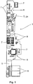
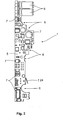
- the Figures 1 and 2 show the device 1 according to the invention for a motor-operated lock 2, which is shown in FIG Figure 3 is shown.
- Electronic components 7 are arranged on a carrier 5, which in the present case is designed as a two-sided printed circuit board.
- the carrier 5 is contoured so that it can be integrated into a lock housing 3 of the motor-operated lock 2.
- the carrier 5 has recesses 8 which leave out functional elements of the motor-operated lock 2, that is to say that the carrier 5 prevents mechanical restrictions on the functional elements of the motor-operated lock 2.
- the electronic components 7 are selected in terms of their arrangement and size such that they follow the contour of the carrier 5.
- an energy-storing element 6 is arranged on the carrier 5.
- This is a capacitor, more precisely two interconnected capacitors that are in direct proximity to one another, which can be designed as supercapacitors.
- the interconnected capacitors are placed on the carrier 5 in such a way that they can be integrated with the carrier 5 in the lock housing 3.
- the capacitors can also be arranged distributed over the carrier 5 and connected together.
- the capacitance of the interconnected capacitors is selected such that the motor-operated lock 2 can be moved into a predefined position via the device 1 according to the invention in the event of a power failure or power interruption.
- the energy in the energy-storing element 6 takes place essentially through electrostatic energy storage, the energy-storing element 6 having at least an energy density of 1J / cm 3 .
- the motor 13 is electrically connected to the energy-storing element 6.
- the motor 13 can be operated via a voltage source (not shown) or via the energy-storing element 6. In normal operation, the motor 13 is supplied with electrical energy via the voltage source.
- the stored energy of the energy-storing element 6 is used to rotate a drive wheel 14 connected to it via the operation of the motor 13 in order, as shown, to move the engagement element 20, which is arranged on the drive wheel 14, to be brought into an out of contact position with the slide 15.
- the energy-storing element 6 can be permanently charged by the voltage source.
- the switch 7, 24 is used to detect the position of the square drive.
- Figure 3 shows schematically in a perspective view an interior view of a motor-operated lock 2 for a door with the one in FIG Figures 1 and 2 shown carrier 5 within the lock housing 3 for the motorized lock 2. Since the individual components of the motorized lock 3 are not relevant to the explanation of the invention, only essential elements of the motorized lock 2 are designated, which are intended for orientation. The functioning of the motor-operated lock 2 and the device 1 according to the invention are therefore not impaired in any way.
- the left side connection of the lock housing 3 is formed by a faceplate 9, which is penetrated by a lock latch 10, an additional latch head 11 and a bolt 12.
- a handle follower 19 is arranged in the motor-operated lock 2 or the lock housing 3 of the motor-operated lock 2 so that it can rotate about an actuation axis.
- An actuating arm 21 is attached to the handle follower 19.
- the actuating arm 21 can be fastened to the handle follower 19 in a force-locking manner.
- the actuating arm 21 is preferably designed in one piece, in particular monolithically, with the handle follower 19. When the handle follower 19 moves about the actuation axis, the actuation arm 21 comes into contact with the slide 15. This leads to a movement, in particular a displacement, of the slide 15.
- the slide 15 is operatively connected to a lock latch 10 and can move it from a locked position to an unlocked position in which the lock latch 10 and the additional latch head 11 are drawn in through the faceplate 9 in the direction of the lock housing 3.
- the slide 15 can be moved in a translatory manner, in particular can be moved linearly, in the motor-driven lock 2, in particular in the lock housing 3.
- a locking mechanism 22 is provided to transfer the movement of the slide 15 into a release of the lock latch 10.
- the motor-driven lock 2 also has a motor 13 with a motor-gear unit for driving the drive wheel 14, which is rotatably mounted about an axis of rotation.
- the motor 13 with the motor-gear unit also serves to unlock the lock latch 10, and in particular to move the slide 15.
- the power of the motor 13 is transmitted via a gear (not shown here) and a transmission element which is in operative contact with the drive wheel 14 is transferred to the slide 15.
- the transmission element can for example be designed as a drive worm.
- the drive wheel 14 which is preferably designed as a gear wheel, in particular as a worm wheel, can be rotated about its axis of rotation.
- the drive wheel 14 is eccentric to the axis of rotation of the drive wheel 14, an engagement element 20 is arranged.
- the engagement element 20 is designed such that when the drive wheel 14 rotates, the engagement element 20 moves the slide 15 via a slide contact surface 23 of the slide 15. In other words, when the slide 15 is displaced, the contact contour of the engagement element 20 slides along the slide contact surface 23.
- the engagement element 20 is in the present case designed as a cam. Due to the structural design of the engagement element 20, the motor only needs a relatively small motor torque in order to move the slide 15. If the engagement element 20 is rotated further, in particular rotated clockwise, the engagement element 20 comes into a contact position with the slide 15 via the contact contour 23 of the slide 15, whereby the translational movement of the slide 15 can be carried out.
- a lock cylinder 16 is located in the lock housing 3.
- the lock cylinder 16 is in operative connection with the slide 15 in such a way that the slide 15 is moved when the lock cylinder 16 is actuated by a key.
- the bolt 12 of the motor-operated lock 2 can be actuated, preferably retracted.
- an actuation axis 19 is arranged in the lock 2 for manual unlocking of the lock.
- An actuating member which is not explicitly shown, can be fastened in the actuating axis 19.
- the actuating member can be a rotary knob, a handle or the like, which can be actuated by a user to open the lock.
- a return spring 17, which acts on the handle follower 19, is arranged below the handle follower 19 or below the drive wheel 14.
- the actuation axis 19, the return spring 17 and the lock cylinder 16, which in the present case form functional elements 18 of the motor-operated lock 2 there is a device 1 according to the invention, the carrier 5 with the switching unit for controlling the device 1 and the energy-storing element 6 comprising, arranged within the lock housing 3.
- the contour of the carrier 5 is designed in such a way that it leaves out the drive wheel 14, the handle follower 19, the return spring 17 and the lock cylinder 16 of the motor-operated lock 2 at least in sections.
- functional elements 18 of lock housing 3, which in the present case serve to lead through locking elements are recessed from the contour of carrier 5.
- the carrier 5 can overlap at least in sections a printed circuit board 4 already built into the lock housing 3, on which, for example, electronics for querying the position of the lock 2 or its control technology is already installed.
- the carrier 5 is connected via this section to the printed circuit board 4 for data and / or voltage slide contact surface.
- the size of the interconnected capacitors is chosen so that they can be found in the lower right corner of the lock housing 3 below a functional element 18 of the lock housing 3.
Landscapes
- Business, Economics & Management (AREA)
- Emergency Management (AREA)
- Physics & Mathematics (AREA)
- Electromagnetism (AREA)
- Lock And Its Accessories (AREA)
Claims (5)
- Serrure (2) motorisée, tout particulièrement serrure anti-panic auto-verrouillante, et un dispositif (1) pour une porte pour l'approvisionnement électrique de la serrure motorisée (2), la serrure (2) comportant un boîtier de serrure (3), un pêne demi-tour de serrure (10) déplaçable entre une position verrouillée et une position déverrouillée, un coulisseau (15) supporté de façon translatoire mobile, de même qu'un mécanisme de blocage (23), sur lequel le coulisseau (15) agit et ainsi libère le pêne demi-tour de serrure (10), et dans laquelle la serrure (2) présente un ensemble moteur-boîte, comportant au moins un moteur (13) pour propulser le coulisseau (15) via un dispositif d'engrènement (20), caractérisés en ce qu'un élément accumulant l'énergie (6) peut être incorporé dans le boîtier de serrure (3), et en ce que l'élément accumulant l'énergie (6) peut être raccordé à une source de tension, et en ce que l'élément (6) accumulant l'énergie est conçu au moins de façon à pouvoir actionner le moteur (13) électriquement en cas de coupure de courant ou une interruption de courant, pour pouvoir déplacer le dispositif d'engrènement (20) hors d'une position de contact avec le coulisseau (15).
- Serrure motorisée (2) et dispositif (1) selon la revendication 1, caractérisés en ce qu'un support (5), sur lequel des composants électroniques (7), aménageant l'unité de commutation, et l'élément accumulant l'énergie (6) sont agencés, peut être incorporé dans le boîtier de serrure (3).
- Serrure motorisée (2) et dispositif (1) selon l'une des revendications précédentes, caractérisés en ce que l'élément accumulant l'énergie (6) est un condensateur ou deux ou plus de condensateurs interconnectés, tout particulièrement des supercondensateurs.
- Serrure motorisée (2) et dispositif (1) selon l'une des revendications 1 à 2, caractérisés en ce que l'élément accumulant l'énergie (6) est un accumulateur ou deux ou plus d'accumulateurs interconnectés.
- Serrure motorisée (2) et dispositif (1) selon l'une des revendications précédentes, caractérisés en ce que le support (5) possède un contour et des dimensions de façon à avoir des renfoncements pour des éléments fonctionnelles de la serrure motorisée (2).
Applications Claiming Priority (1)
| Application Number | Priority Date | Filing Date | Title |
|---|---|---|---|
| DE201310112380 DE102013112380A1 (de) | 2013-11-11 | 2013-11-11 | Gangreserve für ein motorbetriebenes Schloss |
Publications (3)
| Publication Number | Publication Date |
|---|---|
| EP2871307A1 EP2871307A1 (fr) | 2015-05-13 |
| EP2871307B1 EP2871307B1 (fr) | 2017-11-01 |
| EP2871307B2 true EP2871307B2 (fr) | 2020-11-25 |
Family
ID=51866027
Family Applications (1)
| Application Number | Title | Priority Date | Filing Date |
|---|---|---|---|
| EP14191762.5A Active EP2871307B2 (fr) | 2013-11-11 | 2014-11-04 | Réserve de marche pour un verrou motorisé |
Country Status (2)
| Country | Link |
|---|---|
| EP (1) | EP2871307B2 (fr) |
| DE (1) | DE102013112380A1 (fr) |
Families Citing this family (9)
| Publication number | Priority date | Publication date | Assignee | Title |
|---|---|---|---|---|
| DE102016209653B4 (de) | 2016-06-02 | 2024-11-21 | Robert Bosch Gmbh | Energieversorgungsvorrichtung für ein Personenschutzsystem |
| DE102018106832A1 (de) * | 2018-03-22 | 2019-09-26 | Dormakaba Deutschland Gmbh | Gegenschloss für eine Standflügeltür |
| DE102020102601A1 (de) | 2020-02-03 | 2021-08-05 | Schaeffler Technologies AG & Co. KG | Vorladeschaltung zum Vorladen eines Zwischenkreiskondensators |
| DE102021109071A1 (de) | 2021-04-12 | 2022-10-13 | WILKA Schließtechnik GmbH | Elektrischer Öffner für einen Türverschluss |
| DE102021109154A1 (de) * | 2021-04-13 | 2022-10-13 | Assa Abloy Sicherheitstechnik Gmbh | Steuervorrichtung für elektrische Verriegelungsvorrichtungen einer Türe |
| DE102021132044B4 (de) | 2021-12-06 | 2025-10-23 | Assa Abloy Sicherheitstechnik Gmbh | Notstromversorgung für eine elektrische Komponente einer Tür oder eines Fensters |
| CN114412285B (zh) * | 2021-12-31 | 2024-06-14 | 余昊雨 | 一种锁 |
| DE102024107618A1 (de) | 2024-03-18 | 2025-09-18 | Eco Schulte Gmbh & Co. Kg | Schloss mit daran anordbarer Energieversorgungseinrichtung |
| CN119754633B (zh) * | 2024-12-30 | 2026-04-03 | 珠海优特电力科技股份有限公司 | Type-C自驱电子锁芯及其锁具 |
Citations (7)
| Publication number | Priority date | Publication date | Assignee | Title |
|---|---|---|---|---|
| EP1203860A1 (fr) † | 2000-11-06 | 2002-05-08 | Intellectual Trade Cy S.A. | Serrure de sécurité automatique |
| DE202006005567U1 (de) † | 2006-01-12 | 2006-06-14 | Seeland, Denise | Zusatzschloss |
| EP2016243A1 (fr) † | 2006-05-02 | 2009-01-21 | Abloy Oy | Corps de serrure |
| US20100060231A1 (en) † | 2006-01-05 | 2010-03-11 | Tpl, Inc. | Method and Apparatus for Energy Harvesting and/or Generation, Storage, and Delivery |
| US20120169453A1 (en) † | 2010-12-30 | 2012-07-05 | Sargent Manufacturing Company | Electronic lock with power failure control circuit |
| DE102012004337A1 (de) † | 2012-03-07 | 2013-09-12 | General Aerospace GmbH | Verriegelungsvorrichtung |
| EP2837757A2 (fr) † | 2013-08-07 | 2015-02-18 | DORMA Deutschland GmbH | Dispositif pour une porte destinée à l'alimentation électrique d'un composant électrique |
Family Cites Families (4)
| Publication number | Priority date | Publication date | Assignee | Title |
|---|---|---|---|---|
| EP1160399B1 (fr) * | 2000-05-30 | 2005-11-16 | Steinbach & Vollmann GmbH & Co. KG | Serrure commandée électriquement |
| US8265162B2 (en) | 2007-10-01 | 2012-09-11 | Cisco Technology, Inc. | Context adaptive position and amplitude coding of coefficients for video compression |
| DE202010006954U1 (de) * | 2010-05-11 | 2010-08-05 | Bks Gmbh | Schließvorrichtung mit motorischer Antriebseinrichtung |
| CN202117424U (zh) * | 2011-06-01 | 2012-01-18 | 汉王科技股份有限公司 | 一种智能门锁 |
-
2013
- 2013-11-11 DE DE201310112380 patent/DE102013112380A1/de not_active Withdrawn
-
2014
- 2014-11-04 EP EP14191762.5A patent/EP2871307B2/fr active Active
Patent Citations (7)
| Publication number | Priority date | Publication date | Assignee | Title |
|---|---|---|---|---|
| EP1203860A1 (fr) † | 2000-11-06 | 2002-05-08 | Intellectual Trade Cy S.A. | Serrure de sécurité automatique |
| US20100060231A1 (en) † | 2006-01-05 | 2010-03-11 | Tpl, Inc. | Method and Apparatus for Energy Harvesting and/or Generation, Storage, and Delivery |
| DE202006005567U1 (de) † | 2006-01-12 | 2006-06-14 | Seeland, Denise | Zusatzschloss |
| EP2016243A1 (fr) † | 2006-05-02 | 2009-01-21 | Abloy Oy | Corps de serrure |
| US20120169453A1 (en) † | 2010-12-30 | 2012-07-05 | Sargent Manufacturing Company | Electronic lock with power failure control circuit |
| DE102012004337A1 (de) † | 2012-03-07 | 2013-09-12 | General Aerospace GmbH | Verriegelungsvorrichtung |
| EP2837757A2 (fr) † | 2013-08-07 | 2015-02-18 | DORMA Deutschland GmbH | Dispositif pour une porte destinée à l'alimentation électrique d'un composant électrique |
Non-Patent Citations (1)
| Title |
|---|
| K. YAO ET AL.: "Nonlinear dielectric thin films for high-power electric storage with energy density comparable with electrochemical supercapacitors", IEEE TRANSACTIONS ON ULTRASONICS, FERROELECTRICS AND FREQUENCY CONTROL, vol. 58, no. 9, 1 September 2011 (2011-09-01), pages 1968 - 1974 † |
Also Published As
| Publication number | Publication date |
|---|---|
| EP2871307B1 (fr) | 2017-11-01 |
| EP2871307A1 (fr) | 2015-05-13 |
| DE102013112380A1 (de) | 2015-05-13 |
Similar Documents
| Publication | Publication Date | Title |
|---|---|---|
| EP2871307B2 (fr) | Réserve de marche pour un verrou motorisé | |
| EP3532689B1 (fr) | Système d'ouverture et de fermeture comprenant un dispositif de poussée pour un meuble et procédé de fonctionnement d'un système d'ouverture et de fermeture | |
| DE112013003564B4 (de) | Baugruppe mit elektronisch betätigtem Verriegelungsmechanismus für Schubladenschienen | |
| EP2837757B1 (fr) | Dispositif pour une porte destinée à l'alimentation électrique d'un composant électrique | |
| DE102006024685A1 (de) | Elektromechanisches, durch Drücken verschließbares Schloss | |
| AT509465B1 (de) | Vorrichtung zur zutrittskontrolle mit elektromechanischem wandler | |
| DE102022128362A1 (de) | Türgriffanordnung | |
| DE102011110776B4 (de) | Überwachungsvorrichtung zur Positionsbestimmung eines Schlossriegels | |
| DE102008047354A1 (de) | Sperrvorrichtung | |
| EP3126597B1 (fr) | Serrure pour porte ou fenêtre | |
| DE19534609C2 (de) | Selbstverriegelndes Motorschloss | |
| EP4080000B1 (fr) | Dispositif de commande pour dispositifs électriques de verrouillage d'une porte | |
| EP0805905A1 (fr) | Mecanisme de fermeture de porte et organes d'actionnement pour un tel mecanisme | |
| DE20115378U1 (de) | Verriegelungseinrichtung | |
| DE102013212508B4 (de) | Türanlage | |
| DE102014104128B4 (de) | Zuhaltung | |
| DE102013212514B4 (de) | Türanlage mit einer Verriegelungseinrichtung zur Verriegelung eines Türflügels | |
| DE102021114239A1 (de) | Schlüssel mit einer Schlüsselreide und mit einem Schlüsselschaft und einem Generator | |
| EP4239148B1 (fr) | Dispositif de fermeture | |
| DE202017107457U1 (de) | Türschloss mit einem elektromotorischen Antrieb und Türschlossanordnung | |
| WO2009095032A1 (fr) | Interrupteur de sécurité à fonction de verrouillage pour l'ouverture forcée d'éléments de contact et procédé d'ouverture forcée d'éléments de contact d'un interrupteur de sécurité à fonction de verrouillage | |
| DE102021004899B3 (de) | Als modulares System aus wenigstens einem Modul aufgebaute manuelle Notentriegelungseinheit | |
| DE202004001958U1 (de) | Magneto-mechanische Schließeinrichtung II | |
| EP3626917A1 (fr) | Poignée de commande pourvue de système de contrôle d'accès | |
| WO2012130204A1 (fr) | Dispositif de verrouillage pour un dispositif de charge d'un véhicule à moteur |
Legal Events
| Date | Code | Title | Description |
|---|---|---|---|
| PUAI | Public reference made under article 153(3) epc to a published international application that has entered the european phase |
Free format text: ORIGINAL CODE: 0009012 |
|
| 17P | Request for examination filed |
Effective date: 20141104 |
|
| AK | Designated contracting states |
Kind code of ref document: A1 Designated state(s): AL AT BE BG CH CY CZ DE DK EE ES FI FR GB GR HR HU IE IS IT LI LT LU LV MC MK MT NL NO PL PT RO RS SE SI SK SM TR |
|
| AX | Request for extension of the european patent |
Extension state: BA ME |
|
| R17P | Request for examination filed (corrected) |
Effective date: 20151111 |
|
| RBV | Designated contracting states (corrected) |
Designated state(s): AL AT BE BG CH CY CZ DE DK EE ES FI FR GB GR HR HU IE IS IT LI LT LU LV MC MK MT NL NO PL PT RO RS SE SI SK SM TR |
|
| GRAP | Despatch of communication of intention to grant a patent |
Free format text: ORIGINAL CODE: EPIDOSNIGR1 |
|
| STAA | Information on the status of an ep patent application or granted ep patent |
Free format text: STATUS: GRANT OF PATENT IS INTENDED |
|
| RAP1 | Party data changed (applicant data changed or rights of an application transferred) |
Owner name: DORMAKABA DEUTSCHLAND GMBH |
|
| INTG | Intention to grant announced |
Effective date: 20170424 |
|
| GRAS | Grant fee paid |
Free format text: ORIGINAL CODE: EPIDOSNIGR3 |
|
| GRAJ | Information related to disapproval of communication of intention to grant by the applicant or resumption of examination proceedings by the epo deleted |
Free format text: ORIGINAL CODE: EPIDOSDIGR1 |
|
| GRAL | Information related to payment of fee for publishing/printing deleted |
Free format text: ORIGINAL CODE: EPIDOSDIGR3 |
|
| STAA | Information on the status of an ep patent application or granted ep patent |
Free format text: STATUS: REQUEST FOR EXAMINATION WAS MADE |
|
| GRAJ | Information related to disapproval of communication of intention to grant by the applicant or resumption of examination proceedings by the epo deleted |
Free format text: ORIGINAL CODE: EPIDOSDIGR1 |
|
| GRAL | Information related to payment of fee for publishing/printing deleted |
Free format text: ORIGINAL CODE: EPIDOSDIGR3 |
|
| GRAR | Information related to intention to grant a patent recorded |
Free format text: ORIGINAL CODE: EPIDOSNIGR71 |
|
| STAA | Information on the status of an ep patent application or granted ep patent |
Free format text: STATUS: GRANT OF PATENT IS INTENDED |
|
| GRAA | (expected) grant |
Free format text: ORIGINAL CODE: 0009210 |
|
| STAA | Information on the status of an ep patent application or granted ep patent |
Free format text: STATUS: THE PATENT HAS BEEN GRANTED |
|
| INTC | Intention to grant announced (deleted) | ||
| INTC | Intention to grant announced (deleted) | ||
| AK | Designated contracting states |
Kind code of ref document: B1 Designated state(s): AL AT BE BG CH CY CZ DE DK EE ES FI FR GB GR HR HU IE IS IT LI LT LU LV MC MK MT NL NO PL PT RO RS SE SI SK SM TR |
|
| INTG | Intention to grant announced |
Effective date: 20170926 |
|
| REG | Reference to a national code |
Ref country code: GB Ref legal event code: FG4D Free format text: NOT ENGLISH |
|
| REG | Reference to a national code |
Ref country code: CH Ref legal event code: EP Ref country code: AT Ref legal event code: REF Ref document number: 942194 Country of ref document: AT Kind code of ref document: T Effective date: 20171115 |
|
| REG | Reference to a national code |
Ref country code: FR Ref legal event code: PLFP Year of fee payment: 4 Ref country code: IE Ref legal event code: FG4D Free format text: LANGUAGE OF EP DOCUMENT: GERMAN |
|
| REG | Reference to a national code |
Ref country code: CH Ref legal event code: NV Representative=s name: RENTSCH PARTNER AG, CH |
|
| REG | Reference to a national code |
Ref country code: DE Ref legal event code: R096 Ref document number: 502014006031 Country of ref document: DE |
|
| REG | Reference to a national code |
Ref country code: NL Ref legal event code: MP Effective date: 20171101 |
|
| REG | Reference to a national code |
Ref country code: LT Ref legal event code: MG4D |
|
| PG25 | Lapsed in a contracting state [announced via postgrant information from national office to epo] |
Ref country code: FI Free format text: LAPSE BECAUSE OF FAILURE TO SUBMIT A TRANSLATION OF THE DESCRIPTION OR TO PAY THE FEE WITHIN THE PRESCRIBED TIME-LIMIT Effective date: 20171101 Ref country code: SE Free format text: LAPSE BECAUSE OF FAILURE TO SUBMIT A TRANSLATION OF THE DESCRIPTION OR TO PAY THE FEE WITHIN THE PRESCRIBED TIME-LIMIT Effective date: 20171101 Ref country code: LT Free format text: LAPSE BECAUSE OF FAILURE TO SUBMIT A TRANSLATION OF THE DESCRIPTION OR TO PAY THE FEE WITHIN THE PRESCRIBED TIME-LIMIT Effective date: 20171101 Ref country code: NL Free format text: LAPSE BECAUSE OF FAILURE TO SUBMIT A TRANSLATION OF THE DESCRIPTION OR TO PAY THE FEE WITHIN THE PRESCRIBED TIME-LIMIT Effective date: 20171101 Ref country code: NO Free format text: LAPSE BECAUSE OF FAILURE TO SUBMIT A TRANSLATION OF THE DESCRIPTION OR TO PAY THE FEE WITHIN THE PRESCRIBED TIME-LIMIT Effective date: 20180201 Ref country code: ES Free format text: LAPSE BECAUSE OF FAILURE TO SUBMIT A TRANSLATION OF THE DESCRIPTION OR TO PAY THE FEE WITHIN THE PRESCRIBED TIME-LIMIT Effective date: 20171101 |
|
| PG25 | Lapsed in a contracting state [announced via postgrant information from national office to epo] |
Ref country code: RS Free format text: LAPSE BECAUSE OF FAILURE TO SUBMIT A TRANSLATION OF THE DESCRIPTION OR TO PAY THE FEE WITHIN THE PRESCRIBED TIME-LIMIT Effective date: 20171101 Ref country code: LV Free format text: LAPSE BECAUSE OF FAILURE TO SUBMIT A TRANSLATION OF THE DESCRIPTION OR TO PAY THE FEE WITHIN THE PRESCRIBED TIME-LIMIT Effective date: 20171101 Ref country code: GR Free format text: LAPSE BECAUSE OF FAILURE TO SUBMIT A TRANSLATION OF THE DESCRIPTION OR TO PAY THE FEE WITHIN THE PRESCRIBED TIME-LIMIT Effective date: 20180202 Ref country code: BG Free format text: LAPSE BECAUSE OF FAILURE TO SUBMIT A TRANSLATION OF THE DESCRIPTION OR TO PAY THE FEE WITHIN THE PRESCRIBED TIME-LIMIT Effective date: 20180201 Ref country code: IS Free format text: LAPSE BECAUSE OF FAILURE TO SUBMIT A TRANSLATION OF THE DESCRIPTION OR TO PAY THE FEE WITHIN THE PRESCRIBED TIME-LIMIT Effective date: 20180301 Ref country code: HR Free format text: LAPSE BECAUSE OF FAILURE TO SUBMIT A TRANSLATION OF THE DESCRIPTION OR TO PAY THE FEE WITHIN THE PRESCRIBED TIME-LIMIT Effective date: 20171101 |
|
| PG25 | Lapsed in a contracting state [announced via postgrant information from national office to epo] |
Ref country code: SK Free format text: LAPSE BECAUSE OF FAILURE TO SUBMIT A TRANSLATION OF THE DESCRIPTION OR TO PAY THE FEE WITHIN THE PRESCRIBED TIME-LIMIT Effective date: 20171101 Ref country code: CZ Free format text: LAPSE BECAUSE OF FAILURE TO SUBMIT A TRANSLATION OF THE DESCRIPTION OR TO PAY THE FEE WITHIN THE PRESCRIBED TIME-LIMIT Effective date: 20171101 Ref country code: CY Free format text: LAPSE BECAUSE OF FAILURE TO SUBMIT A TRANSLATION OF THE DESCRIPTION OR TO PAY THE FEE WITHIN THE PRESCRIBED TIME-LIMIT Effective date: 20171101 Ref country code: EE Free format text: LAPSE BECAUSE OF FAILURE TO SUBMIT A TRANSLATION OF THE DESCRIPTION OR TO PAY THE FEE WITHIN THE PRESCRIBED TIME-LIMIT Effective date: 20171101 Ref country code: DK Free format text: LAPSE BECAUSE OF FAILURE TO SUBMIT A TRANSLATION OF THE DESCRIPTION OR TO PAY THE FEE WITHIN THE PRESCRIBED TIME-LIMIT Effective date: 20171101 |
|
| REG | Reference to a national code |
Ref country code: DE Ref legal event code: R026 Ref document number: 502014006031 Country of ref document: DE |
|
| PLBI | Opposition filed |
Free format text: ORIGINAL CODE: 0009260 |
|
| PLAX | Notice of opposition and request to file observation + time limit sent |
Free format text: ORIGINAL CODE: EPIDOSNOBS2 |
|
| PG25 | Lapsed in a contracting state [announced via postgrant information from national office to epo] |
Ref country code: SM Free format text: LAPSE BECAUSE OF FAILURE TO SUBMIT A TRANSLATION OF THE DESCRIPTION OR TO PAY THE FEE WITHIN THE PRESCRIBED TIME-LIMIT Effective date: 20171101 Ref country code: RO Free format text: LAPSE BECAUSE OF FAILURE TO SUBMIT A TRANSLATION OF THE DESCRIPTION OR TO PAY THE FEE WITHIN THE PRESCRIBED TIME-LIMIT Effective date: 20171101 Ref country code: LU Free format text: LAPSE BECAUSE OF NON-PAYMENT OF DUE FEES Effective date: 20171104 Ref country code: PL Free format text: LAPSE BECAUSE OF FAILURE TO SUBMIT A TRANSLATION OF THE DESCRIPTION OR TO PAY THE FEE WITHIN THE PRESCRIBED TIME-LIMIT Effective date: 20171101 Ref country code: IT Free format text: LAPSE BECAUSE OF FAILURE TO SUBMIT A TRANSLATION OF THE DESCRIPTION OR TO PAY THE FEE WITHIN THE PRESCRIBED TIME-LIMIT Effective date: 20171101 |
|
| REG | Reference to a national code |
Ref country code: BE Ref legal event code: MM Effective date: 20171130 |
|
| 26 | Opposition filed |
Opponent name: GEZE GMBH Effective date: 20180731 |
|
| REG | Reference to a national code |
Ref country code: IE Ref legal event code: MM4A |
|
| PG25 | Lapsed in a contracting state [announced via postgrant information from national office to epo] |
Ref country code: MT Free format text: LAPSE BECAUSE OF FAILURE TO SUBMIT A TRANSLATION OF THE DESCRIPTION OR TO PAY THE FEE WITHIN THE PRESCRIBED TIME-LIMIT Effective date: 20171101 |
|
| PG25 | Lapsed in a contracting state [announced via postgrant information from national office to epo] |
Ref country code: IE Free format text: LAPSE BECAUSE OF NON-PAYMENT OF DUE FEES Effective date: 20171104 |
|
| PG25 | Lapsed in a contracting state [announced via postgrant information from national office to epo] |
Ref country code: SI Free format text: LAPSE BECAUSE OF FAILURE TO SUBMIT A TRANSLATION OF THE DESCRIPTION OR TO PAY THE FEE WITHIN THE PRESCRIBED TIME-LIMIT Effective date: 20171101 Ref country code: BE Free format text: LAPSE BECAUSE OF NON-PAYMENT OF DUE FEES Effective date: 20171130 |
|
| PLBB | Reply of patent proprietor to notice(s) of opposition received |
Free format text: ORIGINAL CODE: EPIDOSNOBS3 |
|
| PG25 | Lapsed in a contracting state [announced via postgrant information from national office to epo] |
Ref country code: HU Free format text: LAPSE BECAUSE OF FAILURE TO SUBMIT A TRANSLATION OF THE DESCRIPTION OR TO PAY THE FEE WITHIN THE PRESCRIBED TIME-LIMIT; INVALID AB INITIO Effective date: 20141104 Ref country code: MC Free format text: LAPSE BECAUSE OF FAILURE TO SUBMIT A TRANSLATION OF THE DESCRIPTION OR TO PAY THE FEE WITHIN THE PRESCRIBED TIME-LIMIT Effective date: 20171101 |
|
| PG25 | Lapsed in a contracting state [announced via postgrant information from national office to epo] |
Ref country code: MK Free format text: LAPSE BECAUSE OF FAILURE TO SUBMIT A TRANSLATION OF THE DESCRIPTION OR TO PAY THE FEE WITHIN THE PRESCRIBED TIME-LIMIT Effective date: 20171101 |
|
| PG25 | Lapsed in a contracting state [announced via postgrant information from national office to epo] |
Ref country code: TR Free format text: LAPSE BECAUSE OF FAILURE TO SUBMIT A TRANSLATION OF THE DESCRIPTION OR TO PAY THE FEE WITHIN THE PRESCRIBED TIME-LIMIT Effective date: 20171101 |
|
| PG25 | Lapsed in a contracting state [announced via postgrant information from national office to epo] |
Ref country code: PT Free format text: LAPSE BECAUSE OF FAILURE TO SUBMIT A TRANSLATION OF THE DESCRIPTION OR TO PAY THE FEE WITHIN THE PRESCRIBED TIME-LIMIT Effective date: 20171101 |
|
| PG25 | Lapsed in a contracting state [announced via postgrant information from national office to epo] |
Ref country code: AL Free format text: LAPSE BECAUSE OF FAILURE TO SUBMIT A TRANSLATION OF THE DESCRIPTION OR TO PAY THE FEE WITHIN THE PRESCRIBED TIME-LIMIT Effective date: 20171101 |
|
| PUAH | Patent maintained in amended form |
Free format text: ORIGINAL CODE: 0009272 |
|
| STAA | Information on the status of an ep patent application or granted ep patent |
Free format text: STATUS: PATENT MAINTAINED AS AMENDED |
|
| REG | Reference to a national code |
Ref country code: CH Ref legal event code: AELC |
|
| 27A | Patent maintained in amended form |
Effective date: 20201125 |
|
| AK | Designated contracting states |
Kind code of ref document: B2 Designated state(s): AL AT BE BG CH CY CZ DE DK EE ES FI FR GB GR HR HU IE IS IT LI LT LU LV MC MK MT NL NO PL PT RO RS SE SI SK SM TR |
|
| REG | Reference to a national code |
Ref country code: DE Ref legal event code: R102 Ref document number: 502014006031 Country of ref document: DE |
|
| REG | Reference to a national code |
Ref country code: AT Ref legal event code: MM01 Ref document number: 942194 Country of ref document: AT Kind code of ref document: T Effective date: 20191104 |
|
| PG25 | Lapsed in a contracting state [announced via postgrant information from national office to epo] |
Ref country code: AT Free format text: LAPSE BECAUSE OF NON-PAYMENT OF DUE FEES Effective date: 20191104 |
|
| REG | Reference to a national code |
Ref country code: CH Ref legal event code: U11 Free format text: ST27 STATUS EVENT CODE: U-0-0-U10-U11 (AS PROVIDED BY THE NATIONAL OFFICE) Effective date: 20251201 |
|
| PGFP | Annual fee paid to national office [announced via postgrant information from national office to epo] |
Ref country code: DE Payment date: 20251119 Year of fee payment: 12 |
|
| PGFP | Annual fee paid to national office [announced via postgrant information from national office to epo] |
Ref country code: GB Payment date: 20251121 Year of fee payment: 12 |
|
| PGFP | Annual fee paid to national office [announced via postgrant information from national office to epo] |
Ref country code: FR Payment date: 20251125 Year of fee payment: 12 |
|
| PGFP | Annual fee paid to national office [announced via postgrant information from national office to epo] |
Ref country code: CH Payment date: 20251201 Year of fee payment: 12 |