EP2871360A1 - Pompe péristaltique et procédé de pompage, en particulier pour être utilisé comme implant - Google Patents
Pompe péristaltique et procédé de pompage, en particulier pour être utilisé comme implant Download PDFInfo
- Publication number
- EP2871360A1 EP2871360A1 EP20130005256 EP13005256A EP2871360A1 EP 2871360 A1 EP2871360 A1 EP 2871360A1 EP 20130005256 EP20130005256 EP 20130005256 EP 13005256 A EP13005256 A EP 13005256A EP 2871360 A1 EP2871360 A1 EP 2871360A1
- Authority
- EP
- European Patent Office
- Prior art keywords
- pump
- chamber
- driver
- fuel
- fluid
- Prior art date
- Legal status (The legal status is an assumption and is not a legal conclusion. Google has not performed a legal analysis and makes no representation as to the accuracy of the status listed.)
- Withdrawn
Links
- 239000007943 implant Substances 0.000 title claims abstract description 8
- 238000000034 method Methods 0.000 title claims description 12
- 230000002572 peristaltic effect Effects 0.000 title claims description 8
- 238000005086 pumping Methods 0.000 title description 38
- 239000012530 fluid Substances 0.000 claims abstract description 42
- 239000000446 fuel Substances 0.000 claims abstract description 28
- 238000006243 chemical reaction Methods 0.000 claims abstract description 19
- 239000007800 oxidant agent Substances 0.000 claims abstract description 16
- 230000001590 oxidative effect Effects 0.000 claims abstract description 15
- 239000000203 mixture Substances 0.000 claims description 19
- 239000000463 material Substances 0.000 claims description 17
- 239000007795 chemical reaction product Substances 0.000 claims description 7
- 230000008569 process Effects 0.000 claims description 4
- 230000006835 compression Effects 0.000 claims description 3
- 238000007906 compression Methods 0.000 claims description 3
- 125000004122 cyclic group Chemical group 0.000 claims description 3
- 229920001296 polysiloxane Polymers 0.000 claims description 3
- 230000003197 catalytic effect Effects 0.000 claims description 2
- 239000007787 solid Substances 0.000 claims description 2
- 239000013536 elastomeric material Substances 0.000 claims 4
- 229920002943 EPDM rubber Polymers 0.000 claims 2
- 229920002449 FKM Polymers 0.000 claims 1
- 244000043261 Hevea brasiliensis Species 0.000 claims 1
- 239000004743 Polypropylene Substances 0.000 claims 1
- 238000009313 farming Methods 0.000 claims 1
- 239000002657 fibrous material Substances 0.000 claims 1
- 231100001261 hazardous Toxicity 0.000 claims 1
- 229920002681 hypalon Polymers 0.000 claims 1
- 229920003052 natural elastomer Polymers 0.000 claims 1
- 229920001194 natural rubber Polymers 0.000 claims 1
- 150000002825 nitriles Chemical class 0.000 claims 1
- 231100000252 nontoxic Toxicity 0.000 claims 1
- 230000003000 nontoxic effect Effects 0.000 claims 1
- 239000002245 particle Substances 0.000 claims 1
- -1 polypropylene Polymers 0.000 claims 1
- 229920001155 polypropylene Polymers 0.000 claims 1
- 239000004814 polyurethane Substances 0.000 claims 1
- 229920003225 polyurethane elastomer Polymers 0.000 claims 1
- 229920000915 polyvinyl chloride Polymers 0.000 claims 1
- 239000013013 elastic material Substances 0.000 abstract description 2
- 239000007788 liquid Substances 0.000 description 37
- XLYOFNOQVPJJNP-UHFFFAOYSA-N water Substances O XLYOFNOQVPJJNP-UHFFFAOYSA-N 0.000 description 15
- 239000007789 gas Substances 0.000 description 11
- 239000008280 blood Substances 0.000 description 8
- 210000004369 blood Anatomy 0.000 description 8
- UFHFLCQGNIYNRP-UHFFFAOYSA-N Hydrogen Chemical compound [H][H] UFHFLCQGNIYNRP-UHFFFAOYSA-N 0.000 description 7
- 229920001971 elastomer Polymers 0.000 description 7
- 239000001257 hydrogen Substances 0.000 description 6
- 229910052739 hydrogen Inorganic materials 0.000 description 6
- 239000012528 membrane Substances 0.000 description 6
- 238000007789 sealing Methods 0.000 description 5
- 238000006073 displacement reaction Methods 0.000 description 4
- 230000000694 effects Effects 0.000 description 4
- 239000004744 fabric Substances 0.000 description 4
- VNWKTOKETHGBQD-UHFFFAOYSA-N methane Chemical compound C VNWKTOKETHGBQD-UHFFFAOYSA-N 0.000 description 4
- 239000005060 rubber Substances 0.000 description 4
- 229920000742 Cotton Polymers 0.000 description 3
- 210000005242 cardiac chamber Anatomy 0.000 description 3
- 210000000038 chest Anatomy 0.000 description 3
- 239000000806 elastomer Substances 0.000 description 3
- 238000004519 manufacturing process Methods 0.000 description 3
- 229910000510 noble metal Inorganic materials 0.000 description 3
- BASFCYQUMIYNBI-UHFFFAOYSA-N platinum Chemical compound [Pt] BASFCYQUMIYNBI-UHFFFAOYSA-N 0.000 description 3
- 239000007779 soft material Substances 0.000 description 3
- 230000009182 swimming Effects 0.000 description 3
- CSCPPACGZOOCGX-UHFFFAOYSA-N Acetone Chemical compound CC(C)=O CSCPPACGZOOCGX-UHFFFAOYSA-N 0.000 description 2
- 229910001369 Brass Inorganic materials 0.000 description 2
- CURLTUGMZLYLDI-UHFFFAOYSA-N Carbon dioxide Chemical compound O=C=O CURLTUGMZLYLDI-UHFFFAOYSA-N 0.000 description 2
- MHAJPDPJQMAIIY-UHFFFAOYSA-N Hydrogen peroxide Chemical compound OO MHAJPDPJQMAIIY-UHFFFAOYSA-N 0.000 description 2
- XEEYBQQBJWHFJM-UHFFFAOYSA-N Iron Chemical compound [Fe] XEEYBQQBJWHFJM-UHFFFAOYSA-N 0.000 description 2
- 208000007536 Thrombosis Diseases 0.000 description 2
- 239000003146 anticoagulant agent Substances 0.000 description 2
- 229940127219 anticoagulant drug Drugs 0.000 description 2
- 230000008901 benefit Effects 0.000 description 2
- 239000010951 brass Substances 0.000 description 2
- 230000008859 change Effects 0.000 description 2
- 238000000576 coating method Methods 0.000 description 2
- 239000006185 dispersion Substances 0.000 description 2
- 208000015181 infectious disease Diseases 0.000 description 2
- 229910052751 metal Inorganic materials 0.000 description 2
- 239000002184 metal Substances 0.000 description 2
- 239000000047 product Substances 0.000 description 2
- 230000004083 survival effect Effects 0.000 description 2
- 238000010146 3D printing Methods 0.000 description 1
- 101000572820 Homo sapiens MICOS complex subunit MIC60 Proteins 0.000 description 1
- 241001465754 Metazoa Species 0.000 description 1
- 229910000831 Steel Inorganic materials 0.000 description 1
- 230000009471 action Effects 0.000 description 1
- 230000006978 adaptation Effects 0.000 description 1
- QVGXLLKOCUKJST-UHFFFAOYSA-N atomic oxygen Chemical compound [O] QVGXLLKOCUKJST-UHFFFAOYSA-N 0.000 description 1
- 230000015572 biosynthetic process Effects 0.000 description 1
- 230000000740 bleeding effect Effects 0.000 description 1
- 230000017531 blood circulation Effects 0.000 description 1
- 229910002092 carbon dioxide Inorganic materials 0.000 description 1
- 239000001569 carbon dioxide Substances 0.000 description 1
- 239000003054 catalyst Substances 0.000 description 1
- 230000004087 circulation Effects 0.000 description 1
- 239000011248 coating agent Substances 0.000 description 1
- 238000002485 combustion reaction Methods 0.000 description 1
- 238000005056 compaction Methods 0.000 description 1
- 230000007797 corrosion Effects 0.000 description 1
- 238000005260 corrosion Methods 0.000 description 1
- 230000008878 coupling Effects 0.000 description 1
- 238000010168 coupling process Methods 0.000 description 1
- 238000005859 coupling reaction Methods 0.000 description 1
- 230000007423 decrease Effects 0.000 description 1
- 239000003814 drug Substances 0.000 description 1
- 229940079593 drug Drugs 0.000 description 1
- 239000000835 fiber Substances 0.000 description 1
- 239000000945 filler Substances 0.000 description 1
- 229920002313 fluoropolymer Polymers 0.000 description 1
- 239000004811 fluoropolymer Substances 0.000 description 1
- 235000013305 food Nutrition 0.000 description 1
- 210000001035 gastrointestinal tract Anatomy 0.000 description 1
- 230000036541 health Effects 0.000 description 1
- 102000046079 human IMMT Human genes 0.000 description 1
- 230000006698 induction Effects 0.000 description 1
- 238000002347 injection Methods 0.000 description 1
- 239000007924 injection Substances 0.000 description 1
- 230000000968 intestinal effect Effects 0.000 description 1
- 238000005495 investment casting Methods 0.000 description 1
- 229910052742 iron Inorganic materials 0.000 description 1
- 230000002262 irrigation Effects 0.000 description 1
- 238000003973 irrigation Methods 0.000 description 1
- 239000004922 lacquer Substances 0.000 description 1
- 231100000518 lethal Toxicity 0.000 description 1
- 230000001665 lethal effect Effects 0.000 description 1
- 210000004072 lung Anatomy 0.000 description 1
- 239000002207 metabolite Substances 0.000 description 1
- 244000005700 microbiome Species 0.000 description 1
- 239000008267 milk Substances 0.000 description 1
- 210000004080 milk Anatomy 0.000 description 1
- 235000013336 milk Nutrition 0.000 description 1
- 210000004165 myocardium Anatomy 0.000 description 1
- 239000001301 oxygen Substances 0.000 description 1
- 229910052760 oxygen Inorganic materials 0.000 description 1
- 239000011236 particulate material Substances 0.000 description 1
- 239000013618 particulate matter Substances 0.000 description 1
- 230000008855 peristalsis Effects 0.000 description 1
- 239000004033 plastic Substances 0.000 description 1
- 229910052697 platinum Inorganic materials 0.000 description 1
- 229920000642 polymer Polymers 0.000 description 1
- 238000003825 pressing Methods 0.000 description 1
- 230000000541 pulsatile effect Effects 0.000 description 1
- 238000000197 pyrolysis Methods 0.000 description 1
- 239000000376 reactant Substances 0.000 description 1
- 230000002787 reinforcement Effects 0.000 description 1
- 238000009877 rendering Methods 0.000 description 1
- 239000002210 silicon-based material Substances 0.000 description 1
- 229920002379 silicone rubber Polymers 0.000 description 1
- 239000010802 sludge Substances 0.000 description 1
- 239000000243 solution Substances 0.000 description 1
- 239000010959 steel Substances 0.000 description 1
- 239000000725 suspension Substances 0.000 description 1
- 210000001519 tissue Anatomy 0.000 description 1
- 238000002054 transplantation Methods 0.000 description 1
- 239000002699 waste material Substances 0.000 description 1
- 239000002351 wastewater Substances 0.000 description 1
Images

Classifications
-
- F—MECHANICAL ENGINEERING; LIGHTING; HEATING; WEAPONS; BLASTING
- F04—POSITIVE - DISPLACEMENT MACHINES FOR LIQUIDS; PUMPS FOR LIQUIDS OR ELASTIC FLUIDS
- F04B—POSITIVE-DISPLACEMENT MACHINES FOR LIQUIDS; PUMPS
- F04B43/00—Machines, pumps, or pumping installations having flexible working members
- F04B43/12—Machines, pumps, or pumping installations having flexible working members having peristaltic action
- F04B43/14—Machines, pumps, or pumping installations having flexible working members having peristaltic action having plate-like flexible members
-
- A—HUMAN NECESSITIES
- A61—MEDICAL OR VETERINARY SCIENCE; HYGIENE
- A61M—DEVICES FOR INTRODUCING MEDIA INTO, OR ONTO, THE BODY; DEVICES FOR TRANSDUCING BODY MEDIA OR FOR TAKING MEDIA FROM THE BODY; DEVICES FOR PRODUCING OR ENDING SLEEP OR STUPOR
- A61M60/00—Blood pumps; Devices for mechanical circulatory actuation; Balloon pumps for circulatory assistance
- A61M60/10—Location thereof with respect to the patient's body
- A61M60/122—Implantable pumps or pumping devices, i.e. the blood being pumped inside the patient's body
- A61M60/196—Implantable pumps or pumping devices, i.e. the blood being pumped inside the patient's body replacing the entire heart, e.g. total artificial hearts [TAH]
-
- A—HUMAN NECESSITIES
- A61—MEDICAL OR VETERINARY SCIENCE; HYGIENE
- A61M—DEVICES FOR INTRODUCING MEDIA INTO, OR ONTO, THE BODY; DEVICES FOR TRANSDUCING BODY MEDIA OR FOR TAKING MEDIA FROM THE BODY; DEVICES FOR PRODUCING OR ENDING SLEEP OR STUPOR
- A61M60/00—Blood pumps; Devices for mechanical circulatory actuation; Balloon pumps for circulatory assistance
- A61M60/20—Type thereof
- A61M60/247—Positive displacement blood pumps
- A61M60/253—Positive displacement blood pumps including a displacement member directly acting on the blood
- A61M60/268—Positive displacement blood pumps including a displacement member directly acting on the blood the displacement member being flexible, e.g. membranes, diaphragms or bladders
- A61M60/279—Peristaltic pumps, e.g. roller pumps
-
- A—HUMAN NECESSITIES
- A61—MEDICAL OR VETERINARY SCIENCE; HYGIENE
- A61M—DEVICES FOR INTRODUCING MEDIA INTO, OR ONTO, THE BODY; DEVICES FOR TRANSDUCING BODY MEDIA OR FOR TAKING MEDIA FROM THE BODY; DEVICES FOR PRODUCING OR ENDING SLEEP OR STUPOR
- A61M60/00—Blood pumps; Devices for mechanical circulatory actuation; Balloon pumps for circulatory assistance
- A61M60/40—Details relating to driving
- A61M60/424—Details relating to driving for positive displacement blood pumps
-
- F—MECHANICAL ENGINEERING; LIGHTING; HEATING; WEAPONS; BLASTING
- F04—POSITIVE - DISPLACEMENT MACHINES FOR LIQUIDS; PUMPS FOR LIQUIDS OR ELASTIC FLUIDS
- F04B—POSITIVE-DISPLACEMENT MACHINES FOR LIQUIDS; PUMPS
- F04B15/00—Pumps adapted to handle specific fluids, e.g. by selection of specific materials for pumps or pump parts
-
- F—MECHANICAL ENGINEERING; LIGHTING; HEATING; WEAPONS; BLASTING
- F04—POSITIVE - DISPLACEMENT MACHINES FOR LIQUIDS; PUMPS FOR LIQUIDS OR ELASTIC FLUIDS
- F04B—POSITIVE-DISPLACEMENT MACHINES FOR LIQUIDS; PUMPS
- F04B43/00—Machines, pumps, or pumping installations having flexible working members
- F04B43/02—Machines, pumps, or pumping installations having flexible working members having plate-like flexible members, e.g. diaphragms
- F04B43/025—Machines, pumps, or pumping installations having flexible working members having plate-like flexible members, e.g. diaphragms two or more plate-like pumping members in parallel
- F04B43/026—Machines, pumps, or pumping installations having flexible working members having plate-like flexible members, e.g. diaphragms two or more plate-like pumping members in parallel each plate-like pumping flexible member working in its own pumping chamber
-
- F—MECHANICAL ENGINEERING; LIGHTING; HEATING; WEAPONS; BLASTING
- F04—POSITIVE - DISPLACEMENT MACHINES FOR LIQUIDS; PUMPS FOR LIQUIDS OR ELASTIC FLUIDS
- F04B—POSITIVE-DISPLACEMENT MACHINES FOR LIQUIDS; PUMPS
- F04B43/00—Machines, pumps, or pumping installations having flexible working members
- F04B43/12—Machines, pumps, or pumping installations having flexible working members having peristaltic action
-
- F—MECHANICAL ENGINEERING; LIGHTING; HEATING; WEAPONS; BLASTING
- F04—POSITIVE - DISPLACEMENT MACHINES FOR LIQUIDS; PUMPS FOR LIQUIDS OR ELASTIC FLUIDS
- F04B—POSITIVE-DISPLACEMENT MACHINES FOR LIQUIDS; PUMPS
- F04B9/00—Piston machines or pumps characterised by the driving or driven means to or from their working members
- F04B9/08—Piston machines or pumps characterised by the driving or driven means to or from their working members the means being fluid
- F04B9/10—Piston machines or pumps characterised by the driving or driven means to or from their working members the means being fluid the fluid being liquid
- F04B9/109—Piston machines or pumps characterised by the driving or driven means to or from their working members the means being fluid the fluid being liquid having plural pumping chambers
-
- F—MECHANICAL ENGINEERING; LIGHTING; HEATING; WEAPONS; BLASTING
- F04—POSITIVE - DISPLACEMENT MACHINES FOR LIQUIDS; PUMPS FOR LIQUIDS OR ELASTIC FLUIDS
- F04B—POSITIVE-DISPLACEMENT MACHINES FOR LIQUIDS; PUMPS
- F04B9/00—Piston machines or pumps characterised by the driving or driven means to or from their working members
- F04B9/08—Piston machines or pumps characterised by the driving or driven means to or from their working members the means being fluid
- F04B9/12—Piston machines or pumps characterised by the driving or driven means to or from their working members the means being fluid the fluid being elastic, e.g. steam or air
- F04B9/129—Piston machines or pumps characterised by the driving or driven means to or from their working members the means being fluid the fluid being elastic, e.g. steam or air having plural pumping chambers
-
- A—HUMAN NECESSITIES
- A61—MEDICAL OR VETERINARY SCIENCE; HYGIENE
- A61M—DEVICES FOR INTRODUCING MEDIA INTO, OR ONTO, THE BODY; DEVICES FOR TRANSDUCING BODY MEDIA OR FOR TAKING MEDIA FROM THE BODY; DEVICES FOR PRODUCING OR ENDING SLEEP OR STUPOR
- A61M2205/00—General characteristics of the apparatus
- A61M2205/04—General characteristics of the apparatus implanted
-
- A—HUMAN NECESSITIES
- A61—MEDICAL OR VETERINARY SCIENCE; HYGIENE
- A61M—DEVICES FOR INTRODUCING MEDIA INTO, OR ONTO, THE BODY; DEVICES FOR TRANSDUCING BODY MEDIA OR FOR TAKING MEDIA FROM THE BODY; DEVICES FOR PRODUCING OR ENDING SLEEP OR STUPOR
- A61M2210/00—Anatomical parts of the body
- A61M2210/12—Blood circulatory system
- A61M2210/125—Heart
-
- A—HUMAN NECESSITIES
- A61—MEDICAL OR VETERINARY SCIENCE; HYGIENE
- A61M—DEVICES FOR INTRODUCING MEDIA INTO, OR ONTO, THE BODY; DEVICES FOR TRANSDUCING BODY MEDIA OR FOR TAKING MEDIA FROM THE BODY; DEVICES FOR PRODUCING OR ENDING SLEEP OR STUPOR
- A61M60/00—Blood pumps; Devices for mechanical circulatory actuation; Balloon pumps for circulatory assistance
- A61M60/10—Location thereof with respect to the patient's body
- A61M60/122—Implantable pumps or pumping devices, i.e. the blood being pumped inside the patient's body
- A61M60/126—Implantable pumps or pumping devices, i.e. the blood being pumped inside the patient's body implantable via, into, inside, in line, branching on, or around a blood vessel
- A61M60/148—Implantable pumps or pumping devices, i.e. the blood being pumped inside the patient's body implantable via, into, inside, in line, branching on, or around a blood vessel in line with a blood vessel using resection or like techniques, e.g. permanent endovascular heart assist devices
-
- A—HUMAN NECESSITIES
- A61—MEDICAL OR VETERINARY SCIENCE; HYGIENE
- A61M—DEVICES FOR INTRODUCING MEDIA INTO, OR ONTO, THE BODY; DEVICES FOR TRANSDUCING BODY MEDIA OR FOR TAKING MEDIA FROM THE BODY; DEVICES FOR PRODUCING OR ENDING SLEEP OR STUPOR
- A61M60/00—Blood pumps; Devices for mechanical circulatory actuation; Balloon pumps for circulatory assistance
- A61M60/80—Constructional details other than related to driving
- A61M60/855—Constructional details other than related to driving of implantable pumps or pumping devices
- A61M60/89—Valves
- A61M60/894—Passive valves, i.e. valves actuated by the blood
- A61M60/896—Passive valves, i.e. valves actuated by the blood having flexible or resilient parts, e.g. flap valves
Definitions
- the present invention relates to a pump system and a method of operating the same, particularly as an implant into the human body or as a system to pump shear-sensitive fluids.
- liquids can be moved either continuously, or in a pulsating flow.
- Most technical liquids e.g. water, gasoline
- liquids are sensitive to shear stress, i.e. the fact that parts of the liquid move faster than other, adjacent parts of the liquid, or an adjacent mechanically rigid wall.
- the liquids or liquid systems of this class therefore, are difficult to pump and special care is needed to avoid damage to the liquid.
- Important examples of such sensitive liquids are, ordered according to fields:
- any pump requires an energy supply that provides the necessary energy to apply a force onto the liquid.
- a pump needs to convert a source of primary energy input into mechanical movement.
- the pump must in one way or the other apply a force onto the liquid. This transfer induces shear stress, thus making the design of a pump for shear-sensitive liquids challenging.
- peristaltic pump A specific type of pumps is known as peristaltic pump.
- a peristaltic pump the fluid is contained within a flexible tube fitted inside a circular pump casing (though linear peristaltic pumps have been made).
- a rotor with a number of “rollers”, “shoes”, “wipers”, or “lobes” attached to the external circumference of the rotor compresses the flexible tube.
- the part of the tube under compression is pinched closed (or “occludes") thus forcing the fluid to be pumped to move through the tube.
- substitution or "resilience”
- fluid flow is induced to the pump. This process is called peristalsis and is used in many biological systems such as the gastrointestinal tract.
- the second key issue when designing efficient pumps is how to convert primary energy into movement. This issue is particularly pressing when pump and primary energy for driving the pump must be transported (i.e. in portable systems, or on-board systems).
- a particularly challenging pumping application are human heart assist devices (technical devices that help the heart of patients to move the blood through the body) or artificial heart implants such as total implants or artificial hearts, which are herein understood as a technical device pumping a patient's blood through the body, whether placed inside the body as implant or as part of life support system attached via fluid transporting tubes to a patient's circulation system.
- the available space in the thorax of a patient, or (less preferred) in the lower intestinal space is extremely limited and a pump has to be of small volume and simultaneously very efficient to be considered as suitable.
- the first generation of pumps used to replace human hearts were pulsatile devices based on a two-chamber design, where the chambers were separated by a membrane. One chamber is used for pumping the blood, while the other is filled with a gas. The gas was used to deform the membrane by changing its pressure, and thus change the volume in the blood chamber, which results in movement of the blood.
- This approach is similar to the biological design of the human heart since later also contains two chambers, but clinical studies showed that the design was insufficient, as patients suffered from infection (28%) and 35% of all cases underwent a failure of the device.
- Anticoagulants had to be applied at all times, and result in a significant number of strokes as a side-effect of the blood thinner. This design was so big, that most of it was used extracorporeal (i.e. the patient had the pump above the chest, and needed to carry a larger pump and battery pack.
- a second and third generation of heart assist and replacement devices is based on the use of continuous flow, (cf) pumps, e.g. as described in N Engl J Med 2009 361 2241-51 and had a much better clinical outcome.
- the performance of a technical device is usually compared to the outcome of a heart transplantation which results in a survival of 84, or 80% of the patients after 1 or 2 years, respectively.
- the current miniaturization of the cf pumps results in higher and higher blade speed, and associated high shear stress. This is clinically evident through the appearance of pump thrombosis that is responsible for 54% of all cases where patients died as described in J Thorac Cardiovasc Surg, 2013, Volume 146, pages 437-441 .
- a peristaltic pump driven be a volume expansion following a chemical reaction between fuel and oxidant.
- the term "peristaltic" is chosen to indicate that the pump chamber through which the fluid is pumped has at least partly flexible exterior walls.
- reaction it is possible to allow the reaction to occur in a separate pyrolysis chamber and feed the reaction products into a driver chamber. Alternatively the reaction can take place directly in a driver chamber.
- the driver chamber preferably shares an inter-chamber wall with a fluid pump chamber such that deformation of the inter-chamber wall decreases or increases the volume of the pump chamber.
- the inter-chamber wall is best less stiff than other, exterior walls of the chambers.
- Driver chambers and pump chambers can be arranged as pairs, for example such that a driver chamber acts predominantly or even exclusively onto the pump chamber with which it is paired.
- a pump can have two pump and two driver chambers, preferably with the two driver chamber having different inner volume.
- the driver chambers are located around a core volume of the pump occupied by the pump chambers. This variant can be regarded as a concentric pump design with central pump chambers.
- one pump chamber is associated (and hence co-located) with two driver chambers.
- the pump includes best an ignition controller which controls the timing of reactions associated with different driver chambers to control the pumping operation of the pump.
- the ignition controller can be adapted to provide the initial energy to initiate a chemical reaction, for example in form of a spark, or control the supply and/or exhaust of fuel and/or oxidant. The latter is particularly preferred in variants of the pump for which the reaction is self-igniting.
- Catalytic material can be placed at the desired location of the chemical reaction, particularly within a driver chamber, to promote the reaction or self-ignition.
- the material of the pump components i.e. of the fluid pump chamber, driver chambers and their permanent content, consists of at least 80%, preferably above 90%, of a soft material such as the elastomeric materials referred to above.
- the material can further include base material with embedded fibers, for example in locations which are designed to have a higher stiffness than other locations made of the same base materials.
- the above components are made of a single material, more preferably of a soft material such as the elastomeric materials referred to above.
- the walls between chambers are designed to be easier deformable than the walls between the chambers and the exterior, i.e. the same tensile force or pressure applied lead to a greater deformation of an inter-chamber wall than an exterior wall.
- the pumps described herein are useful for the transport of water, waste water, sludge, or other fluids, e.g. in agricultural settings.
- the pump is usually connected at its exit with a tube that guides the liquid to a final site of use, e.g. a truck, an irrigation channel, a biotechnological reactor, or a feed line in an animal facility.
- a soft, combustion driven pump can in principle replace many classical rotary or piston driven pumps.
- a key advantage of this alternative is its simple design, particularly if made from few elastomers or even a single elastomer. Such simple design is advantageous over classical (hard, metal and hard plastic component based) pumps, as it avoids sealing problems (e.g.
- the described pumps are advantageous used in applications where chemically very reactive liquids must be pumped, or if very dangerous liquids must be transported, particularly if containment of the liquid is an health or safety issue, and current sealing methods are insufficient, or very costly (e.g. through the use of crosslinked fluoropolymers, which provide a very good sealing, but are very expensive to manufacture.)
- silicon rubber based pumps in accordance with this embodiment can be very corrosion resistant.
- the pumps are advantageous applied in conveying suspensions, as they combine independence from sealing (particulate matter usually creates problems in and at seals), and avoid wear, a typical problem in classical, hard wheel-driven peristaltic pumps such as P_classicplus-twin of Ponndorf Act-technik GmbH, Kassel Germany, or ALH 10 (Steinle-Pumpen).
- wear is often a result of the severe deformation of the polymer tube by the external driver wheels and can be avoided using an embodiment of the present invention.
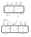
- FIG. 1 A first schematic representation of a basic device in accordance with an example of the invention is shown in FIG. 1 .
- the device of FIG. 1 is a two chamber pump 10 having a fluid pump chamber 11 and a driver chamber 12.
- the walls of the chambers are made of a silicone based material.
- the inter-chamber wall 13 is made of a reduced thickness compared to the exterior walls.
- Ports 122, 123 in the exterior walls of the driver chamber provide a supply path to a fuel and oxidant reservoir (not shown) and an exhaust path for reaction products.
- Ports 111, 112 in the exterior wall of the fluid pump chamber provide inlet and outlet, respectively, for fluid to be pumped.
- An ignition device 14 is integrated into one exterior wall and at least partly exposed to the interior of the driver chamber 12.
- the device can include for example two electrodes connected to two poles of a voltage source in a manner similar to a spark plug.
- FIGs. 2A to 2C Elements of a three chamber pump in accordance with an example of the invention are shown in FIGs. 2A to 2C .
- the pump differs from the pump of FIG. 1 by addition of a second drive chamber 12. Hence the pump has two inter-chamber walls 13-1 13-2.
- the elements of the second driver chamber 12 are identical to those of the first driver chamber already described above, the same numerals have been used to denote the same elements.
- one chamber serves as a driver chamber, one as a liquid pumping chamber and one chamber assists the aspiration of air as oxidant, for example for use in a later stage of a pump operation cycle.
- This intake of air can be used advantageously in an embodiment where the two driver chambers 12 that are each used in a pump cycle as described in further detail below alternating as exhaust/intake chamber, i.e., first as expansion chamber and in the following pump cycle as exhaust/intake chamber, and so forth.
- the chambers 12 may either be arranged in a linear way, with the fluid pumping chamber 11 in the middle, or, the two driver chambers may be next to one another, sharing a common wall (driver 1/driver 2) and both a common wall with the pumping chamber.
- the wall thickness of (driver 1/driver 2) will be different from the wall (driver 1 or 2/pumping).
- Chambers may include sensors to measure fluid concentration levels etc.
- a pump as shown in FIG. 2 can be operated according to the following cyclic steps:
- Valves at the entry and exit points of the individual chambers direct the flow of gas or liquids typically in a unidirectional way and avoid backflow of liquids or gases.
- Suitable valves are known in this field and can consist of ball valves or flap-based valves, amongst others.
- Step 3 System relaxes to its initial state as the elastic material restores all chambers of the pump back to their most relaxed form.
- the first driver chamber 12 cools down whilst the fluid pumping chamber 11 sucks in fluid up to its relaxed position (usually straight walls) and the second driver chamber 12 refills by taking in the fuel mixture.
- the fuel mixture can be injected or sucked in into second driver chamber 12.
- FIG. 2C which is identical to FIG. 2A with the role of fuel-filled and exhaust filled driver chamber 12 reversed.
- the deformation used for the pumping can also be used to provide a valve-like action on supply and/or exhaust tubes.
- deformable sections of tubular connectors to the ports can be used, which are closed and opened through the expansion or compression of driver chambers.
- the soft design of the pump hence permits to have deformable sections of tubing at inlet or exit of gas/liquid ports. Deformation due to use of a driver chamber then alters the opening in such deformable sections, hence permitting some control on the flow through that section.
- the ports can optionally be open or covered by a permeable membrane, for example a hydrophilic, semipermeable membrane. Due to its hydrophilicity, the membrane can permit slow transfer of water out of the liquid pump. In such a design, water as a waste product is slowly released out of the driver chamber similar to a drain. This exploits an effect similar to wetted fabric (e.g. woven cotton), which is known to be nearly impermeable for air, while water can flow almost freely through it. This effect is best known when cotton cloth get soaked with water and held under water with air trapped inside. Driving air through wetted cotton requires significant pressure. Since the pressure depends on the mesh width of the cloth, finer fabrics withstand higher pressure. This allows the adaptation of the membrane to a given design or purpose.
- a permeable membrane for example a hydrophilic, semipermeable membrane. Due to its hydrophilicity, the membrane can permit slow transfer of water out of the liquid pump. In such a design, water as a waste product is slowly released out of the driver chamber similar
- the fuel can include for example a volatile organic, combustible liquid and hydrogen peroxide or of a gas mixture such as hydrogen gas and air.
- the fuel can be ignited electrically using sparks as generated by the ignition controller 14.
- the ignition controller can include a catalyst, such as a noble metal or metal composition including a noble metal, igniting the fuel mixture at defined concentration levels of fuel and oxidant.
- a self-igniting effect is used, well known from the ignition of hydrogen containing gas mixtures on fine powdered noble metals, particularly platinum, as platinum sponge.
- This effect is known from the so called Döbereiner' Fire lighter.
- the control on the pumping cycle is then possible through timing the inflow of reactants (e.g. hydrogen and air): If fuel (e.g. hydrogen) is being fed very slowly into the driver chamber, it takes more time to reach critical hydrogen concentration for ignition then when the hydrogen flow is higher. Hence, the frequency of the ignition and hence pumping can be controlled to a certain extent by the hydrogen feed rate.
- a four chamber design can be advantageous, as it resembles the biological design of the human heart.
- an even higher number of chambers may be used.
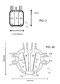
- FIG. 4 there is shown an example of a pump with an aspect ratio of 1:1 between height and diameter.
- Such an aspect ratio leading to a relatively shallow volume of the chamber and long inter-chamber walls is preferred to increase the efficiency of the pump.
- the geometry of the natural, human heart chamber can be better matched.
- the pumping chamber is then an asymmetric chamber as in a biological heart chamber, and at least partly surrounded by a driver chamber in a geometry similar to the natural heart muscle. This arrangement is very efficient to transform the expansion of the driver chamber into pushing/compaction of the liquid chamber. Ignition and feed ports are then preferably located at the outside of this concentric arrangement.
- two pumping chambers similar to the natural human heart are needed.
- the two pumping chambers are dissimilar in size (the left and right heart chambers are of different strength as the lung branch of the blood circulation has less flow resistance and hence a lower pressure than the larger main branch of the heart, with higher liquid pressure).
- Both chambers are each surrounded at least to a large extent by a driver chamber.
- the driver chamber takes the volume between an approximately cylindrical pump chamber in the center, and the outer envelope or wall of the pump itself. Typical chambers will be 2-5 times longer (if the pump is located in a similar fashion as a human heart in a standing human being) then wide.
- the aspect ratio of 2:1 - 5:1 and design is similar to the human heart muscle.
- the outside wall of the pump are more resistant to expansion than the wall separating a driver chamber from a pumping chamber.
- FIG. 4A - 4C Examples of four chamber pumps with these aspect ratios are shown in FIG. 4A - 4C .
- the pump 10 has two inner driver chambers 12 and two outer fluid pump chambers 11.
- Each of the fluid pump chambers 11 have two fluid intake ports 111 and one exit port 112.
- the material is a room temperature vulcanizing silicone NeukasilTM RTV21 (Vulcanizer VN A 7, vulcanized at 50°C) as provided by Altropol Kunststoffe GmbH, Stockelsdorf, Gemany.
- the material is extremely flexible having breaking elongation of about 1000%.
- the shape as shown can be manufactured using for example investment casting with the cast from ABS generated through a 3D printing process and later dissolved in an acetone solution.
- the pump has a material volume of 485 cm ⁇ 3 of silicone (weight: 530 g) with the volume of a driver chamber 11 95 cm ⁇ 3 and the volume of a pumping chamber 12 60 cm ⁇ 3.
- the inter-chamber walls 13-1, 13-2 have a thickness of 3 mm while the exterior walls have a thickness of 8 mm.
- the inner driver chambers 12 are alternatingly filled with a methane/air mixture and ignited at (4.8 Volt, 3 A) using a commercially available electronic igniter.
- the driver chambers are filled with a gas flow 0.22 L/min of CH4 (at 0.25 Hz pumping frequency) and 2.2 L/min Air (at 0.25 Hz pumping frequency).
- the replacement of burned gas volume in a driver chamber is approximately 85% at the flow rate as stated. If the pump is operated at higher frequency (e.g. 1 Hz), the gas flow rates and ignition are increased to 0.9 L/min of CH4 (at 1.0 Hz pumping frequency) and 9 L/min Air.
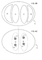
- the relative arrangement of pumping chambers and driver chambers is reversed compared to the 4 chamber pump of FIG. 4A .
- the pumping chambers 11 occupy an essentially cylindrical core volume in the center of the pump 10, whilst the driver chambers 12 are located between the core volume and the outer walls of the pump.
- FIG. 4B shows a layer of the pump 10 at about mid-height.
- One of the driver chambers 12 is larger than the other, thus rendering the design asymmetric.
- the second cross-sectional view ( FIG. 4C ) is taken from above the pump.
- the locations of the interior pump chambers 11 are indicated as dashed line.
- a dotted line shows the location of the vertical central plane of the pump thus emphasising the asymmetric design of the pump.
- Each pump chamber 11 has an inlet port 111 and an outlet port 112 to provide pumping fluid transport into and out of the pump.
Landscapes
- Engineering & Computer Science (AREA)
- Health & Medical Sciences (AREA)
- Mechanical Engineering (AREA)
- Heart & Thoracic Surgery (AREA)
- General Engineering & Computer Science (AREA)
- Cardiology (AREA)
- Anesthesiology (AREA)
- Biomedical Technology (AREA)
- Hematology (AREA)
- Life Sciences & Earth Sciences (AREA)
- Animal Behavior & Ethology (AREA)
- General Health & Medical Sciences (AREA)
- Public Health (AREA)
- Veterinary Medicine (AREA)
- Reciprocating Pumps (AREA)
Priority Applications (4)
| Application Number | Priority Date | Filing Date | Title |
|---|---|---|---|
| EP20130005256 EP2871360A1 (fr) | 2013-11-07 | 2013-11-07 | Pompe péristaltique et procédé de pompage, en particulier pour être utilisé comme implant |
| EP14781048.5A EP3066342B1 (fr) | 2013-11-07 | 2014-10-01 | Pompe péristaltique et procédé de pompage, en particulier pour être utilisé comme implant |
| PCT/CH2014/000141 WO2015066824A1 (fr) | 2013-11-07 | 2014-10-01 | Pompe péristaltique et procédé de pompage, à utiliser en particulier comme implant |
| US15/033,377 US10549021B2 (en) | 2013-11-07 | 2014-10-01 | Peristaltic pump and pumping method, in particular for use as implant |
Applications Claiming Priority (1)
| Application Number | Priority Date | Filing Date | Title |
|---|---|---|---|
| EP20130005256 EP2871360A1 (fr) | 2013-11-07 | 2013-11-07 | Pompe péristaltique et procédé de pompage, en particulier pour être utilisé comme implant |
Publications (1)
| Publication Number | Publication Date |
|---|---|
| EP2871360A1 true EP2871360A1 (fr) | 2015-05-13 |
Family
ID=49584576
Family Applications (2)
| Application Number | Title | Priority Date | Filing Date |
|---|---|---|---|
| EP20130005256 Withdrawn EP2871360A1 (fr) | 2013-11-07 | 2013-11-07 | Pompe péristaltique et procédé de pompage, en particulier pour être utilisé comme implant |
| EP14781048.5A Not-in-force EP3066342B1 (fr) | 2013-11-07 | 2014-10-01 | Pompe péristaltique et procédé de pompage, en particulier pour être utilisé comme implant |
Family Applications After (1)
| Application Number | Title | Priority Date | Filing Date |
|---|---|---|---|
| EP14781048.5A Not-in-force EP3066342B1 (fr) | 2013-11-07 | 2014-10-01 | Pompe péristaltique et procédé de pompage, en particulier pour être utilisé comme implant |
Country Status (3)
| Country | Link |
|---|---|
| US (1) | US10549021B2 (fr) |
| EP (2) | EP2871360A1 (fr) |
| WO (1) | WO2015066824A1 (fr) |
Families Citing this family (2)
| Publication number | Priority date | Publication date | Assignee | Title |
|---|---|---|---|---|
| WO2020006324A1 (fr) * | 2018-06-27 | 2020-01-02 | Steve Smith | Dispositif artificiel péristaltique d'assistance cardiaque et ventriculaire |
| CN111156330B (zh) * | 2020-01-08 | 2021-10-26 | 深圳铂今节能科技有限公司 | 一种节能环保的多工位周期水循环装置 |
Citations (4)
| Publication number | Priority date | Publication date | Assignee | Title |
|---|---|---|---|---|
| GB2010385A (en) * | 1977-07-06 | 1979-06-27 | Richardson P | Pump |
| EP0209644A1 (fr) * | 1985-05-02 | 1987-01-28 | Ivac Corporation | Distributeur de produit pharmaceutique à commande électrochimique |
| US5571261A (en) * | 1993-08-06 | 1996-11-05 | River Medical, Inc | Liquid delivery device |
| WO2002093665A2 (fr) * | 2000-11-21 | 2002-11-21 | Mti Microfuel Cells, Inc. | Systeme de pile a combustible a alimentation liquide a pompage passif |
Family Cites Families (1)
| Publication number | Priority date | Publication date | Assignee | Title |
|---|---|---|---|---|
| US4886514A (en) * | 1985-05-02 | 1989-12-12 | Ivac Corporation | Electrochemically driven drug dispenser |
-
2013
- 2013-11-07 EP EP20130005256 patent/EP2871360A1/fr not_active Withdrawn
-
2014
- 2014-10-01 US US15/033,377 patent/US10549021B2/en not_active Expired - Fee Related
- 2014-10-01 EP EP14781048.5A patent/EP3066342B1/fr not_active Not-in-force
- 2014-10-01 WO PCT/CH2014/000141 patent/WO2015066824A1/fr not_active Ceased
Patent Citations (4)
| Publication number | Priority date | Publication date | Assignee | Title |
|---|---|---|---|---|
| GB2010385A (en) * | 1977-07-06 | 1979-06-27 | Richardson P | Pump |
| EP0209644A1 (fr) * | 1985-05-02 | 1987-01-28 | Ivac Corporation | Distributeur de produit pharmaceutique à commande électrochimique |
| US5571261A (en) * | 1993-08-06 | 1996-11-05 | River Medical, Inc | Liquid delivery device |
| WO2002093665A2 (fr) * | 2000-11-21 | 2002-11-21 | Mti Microfuel Cells, Inc. | Systeme de pile a combustible a alimentation liquide a pompage passif |
Also Published As
| Publication number | Publication date |
|---|---|
| US10549021B2 (en) | 2020-02-04 |
| EP3066342B1 (fr) | 2018-07-04 |
| WO2015066824A1 (fr) | 2015-05-14 |
| EP3066342A1 (fr) | 2016-09-14 |
| US20160250401A1 (en) | 2016-09-01 |
Similar Documents
| Publication | Publication Date | Title |
|---|---|---|
| CN1916411B (zh) | 基于电活性聚合物的泵 | |
| US11572871B2 (en) | Low-force pumping segment | |
| EP2501935A1 (fr) | Pompe | |
| US10549021B2 (en) | Peristaltic pump and pumping method, in particular for use as implant | |
| US20020081207A1 (en) | Linear pump and method | |
| JP2011500115A5 (fr) | ||
| CN105796340A (zh) | 一种无菌配药系统 | |
| CN104906643A (zh) | 一种血液泵送装置 | |
| CN1829544A (zh) | 用于进行流体施用的系统 | |
| WO2024132528A1 (fr) | Tube à particules magnétiques intégrées et dispositif de pompage associé | |
| US20190117202A1 (en) | Devices and methods for automated filling and dispensing of adipose tissue with control of shear | |
| CN110230585A (zh) | 压力真空控制泵 | |
| DK181371B1 (en) | An industrial process of processing a mycelium panel material | |
| CN201138990Y (zh) | 针筒活塞式珍稀鱼类灌喂装置 | |
| CN116589152B (zh) | 一种集约型自来水处理装置 | |
| CN113764838B (zh) | 真空注液装置 | |
| CN215933786U (zh) | 真空注液装置 | |
| DK181603B1 (en) | A mycelium processing system and a method of using a mycelium processing system | |
| CN211767424U (zh) | 双层一次性储液袋及其恒压输送装置 | |
| CN204521595U (zh) | 气动针管助力器 | |
| CN208511582U (zh) | 一种便携式伤口治疗装置 | |
| JP6326556B2 (ja) | 搬送装置 | |
| CN113365676A (zh) | 带有功能性真空脉冲的吸乳泵 | |
| CN85101745A (zh) | 人造心脏 | |
| US8859269B2 (en) | Chemical activation of an actuator or an osmotic motor |
Legal Events
| Date | Code | Title | Description |
|---|---|---|---|
| PUAI | Public reference made under article 153(3) epc to a published international application that has entered the european phase |
Free format text: ORIGINAL CODE: 0009012 |
|
| 17P | Request for examination filed |
Effective date: 20131107 |
|
| AK | Designated contracting states |
Kind code of ref document: A1 Designated state(s): AL AT BE BG CH CY CZ DE DK EE ES FI FR GB GR HR HU IE IS IT LI LT LU LV MC MK MT NL NO PL PT RO RS SE SI SK SM TR |
|
| AX | Request for extension of the european patent |
Extension state: BA ME |
|
| STAA | Information on the status of an ep patent application or granted ep patent |
Free format text: STATUS: THE APPLICATION IS DEEMED TO BE WITHDRAWN |
|
| 18D | Application deemed to be withdrawn |
Effective date: 20151114 |