EP2871429A2 - Variables Stromversorgungsgerät für gleichmäßige Erwärmung von Flüssigkeiten - Google Patents
Variables Stromversorgungsgerät für gleichmäßige Erwärmung von Flüssigkeiten Download PDFInfo
- Publication number
- EP2871429A2 EP2871429A2 EP20140425140 EP14425140A EP2871429A2 EP 2871429 A2 EP2871429 A2 EP 2871429A2 EP 20140425140 EP20140425140 EP 20140425140 EP 14425140 A EP14425140 A EP 14425140A EP 2871429 A2 EP2871429 A2 EP 2871429A2
- Authority
- EP
- European Patent Office
- Prior art keywords
- tube
- fluid
- heat sink
- power device
- variable power
- Prior art date
- Legal status (The legal status is an assumption and is not a legal conclusion. Google has not performed a legal analysis and makes no representation as to the accuracy of the status listed.)
- Granted
Links
Images

Classifications
-
- H—ELECTRICITY
- H05—ELECTRIC TECHNIQUES NOT OTHERWISE PROVIDED FOR
- H05B—ELECTRIC HEATING; ELECTRIC LIGHT SOURCES NOT OTHERWISE PROVIDED FOR; CIRCUIT ARRANGEMENTS FOR ELECTRIC LIGHT SOURCES, IN GENERAL
- H05B3/00—Ohmic-resistance heating
- H05B3/40—Heating elements having the shape of rods or tubes
- H05B3/42—Heating elements having the shape of rods or tubes non-flexible
- H05B3/44—Heating elements having the shape of rods or tubes non-flexible heating conductor arranged within rods or tubes of insulating material
-
- F—MECHANICAL ENGINEERING; LIGHTING; HEATING; WEAPONS; BLASTING
- F24—HEATING; RANGES; VENTILATING
- F24H—FLUID HEATERS, e.g. WATER OR AIR HEATERS, HAVING HEAT-GENERATING MEANS, e.g. HEAT PUMPS, IN GENERAL
- F24H1/00—Water heaters, e.g. boilers, continuous-flow heaters or water-storage heaters
- F24H1/10—Continuous-flow heaters, i.e. heaters in which heat is generated only while the water is flowing, e.g. with direct contact of the water with the heating medium
- F24H1/12—Continuous-flow heaters, i.e. heaters in which heat is generated only while the water is flowing, e.g. with direct contact of the water with the heating medium in which the water is kept separate from the heating medium
- F24H1/14—Continuous-flow heaters, i.e. heaters in which heat is generated only while the water is flowing, e.g. with direct contact of the water with the heating medium in which the water is kept separate from the heating medium by tubes, e.g. bent in serpentine form
- F24H1/142—Continuous-flow heaters, i.e. heaters in which heat is generated only while the water is flowing, e.g. with direct contact of the water with the heating medium in which the water is kept separate from the heating medium by tubes, e.g. bent in serpentine form using electric energy supply
-
- H—ELECTRICITY
- H05—ELECTRIC TECHNIQUES NOT OTHERWISE PROVIDED FOR
- H05B—ELECTRIC HEATING; ELECTRIC LIGHT SOURCES NOT OTHERWISE PROVIDED FOR; CIRCUIT ARRANGEMENTS FOR ELECTRIC LIGHT SOURCES, IN GENERAL
- H05B2203/00—Aspects relating to Ohmic resistive heating covered by group H05B3/00
- H05B2203/021—Heaters specially adapted for heating liquids
Definitions
- the present invention generally relates to a variable power device for a uniform heating of fluids.
- the invention concerns a resistor device which is suitably realized and has a considerable exchange surface with the fluid, so as to obtain an instantaneous and homogeneous heating of the fluid passing within the structure, thus maximizing the load losses and also saving in terms of space and/or dimensions.
- the hot water for sanitary use is normally obtained by passing cold water through a plate heat exchanger, inside which a hot fluid is sent through a secondary circuit of the exchanger, in order to maintain a substantially constant temperature of the fluid at the output.
- the temperature of the output water usually between 55 °C and 60 °C, and, for many applications, it is also preferable to directly heat the output fluid flow, so as to avoid the use of holding tanks.
- the heating fluid which is sent inside the heat exchanger must have a temperature of about 10°C-20°C higher than the predetermined value of temperature of the water coming out from the tap, and because, when the tap is closed, the water contained in the heat exchanger is brought to the temperature of the heating fluid, when the tap is reopened, the output water has, for a certain time interval, a temperature higher by 10°C-20°C than the predetermined value of 55°C-60 °C.
- the present invention is therefore devoted to overcome the above mentioned drawbacks of the prior art and, in particular, the main object of the invention is to provide a variable power device for a uniform heating of fluids, which is configured for instantaneously providing a uniformly heated water flow to one or more users, at a predetermined value of temperature, which is controlled and substantially homogeneous.
- Another object of the invention is to provide a variable power device for a uniform heating of fluids, which can be used together with a heat exchanger, in order to obtain an extremely efficient and compact device, suitable to deliver almost instantaneously a water flow which is always uniformly heated.
- Another object of the invention is to provide a variable power device for a uniform heating of fluids, which is able to obtain a total heat exchange circuit, without the use of any fuel tank and/or fluid container, nor any pipe connection between the resistor device and the heat exchanger, thus limiting the overall dimensions and saving in terms of time and/or of water.
- a further object of the invention is to provide a variable power device for a uniform heating of fluids, which is particularly effective, reliable, convenient and cheap, with respect to the prior art, and which can be used for any new or existing water supply.
- variable power device for a uniform heating of fluids, according to the appended claim 1.
- the device according to the invention allows to quickly heat a fluid flow and to instantly obtain an output flow having a totally controlled and homogeneous temperature, by using a labyrinth-shaped resistor, which works as a heat exchanger within a total heat exchange device; the heat exchange takes place immediately, thus obtaining a consequent and considerable saving in terms of fluid dispensed and of time taken for heating the fluid, with respect to the prior art.
- the device of the invention is usable in particular for supplying hot water, but can be similarly used for any other private and/or industrial use (for example, as a heat exchanger for plastic materials molding machines) for which it is necessary to have a continuous quantity of fluid at a homogeneous and controlled temperature value.
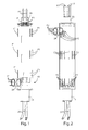
- variable power device for a uniform heating of fluids, according to the invention, and from the enclosed drawings, in which:
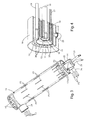
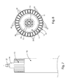
- the device essentially comprises an outer tube 10 and a first perforated sink element 13, made of conductive material and preferably aluminum, inside which are inserted, starting from the periphery and proceeding towards the center of the device, a first cavity 11, a resistor 12, which is preferably embedded within an insulating layer made of compressed magnesium oxide, a second cavity 15 and a second heat sink element 16, which is star-shaped and made of a conductive material, such as aluminum.
- the heat sink element 16 can also be missing, in which case it is possible to use a circular end plate which contacts the walls of the cavity 15.
- the tube 10 is connected to a further length of tube 14, by means of a ring nut and/or a special flange, for connecting the 3-phase power cables and the grounding cables 21 and the cables 20 for connecting a possible insulating thermocouple.
- said tube 10 can be coupled with one or more connectors 24 for delivering fluids, for example T-type connectors, and/or with a support base 25 for connecting a thermostat (optional) (the support base 25 is placed in particular on a copper pad in contact with the external heat sink element 13).
- the described structure allows to provide, according to the present invention, a plurality of possible points of temperature control, by using, for example, a safety thermocouple 17, placed on the resistive wire or layer 18, within the resistor 12, and a plurality of containment elements 19 of respective bulbs placed inside the star-shaped heat sink 16, within the resistor 12 and on the external heat sink 13, in contact with the fluid.
- variable power device for a uniform heating of fluids provides firstly the entry of the fluid F1 from a lower side connector 24, the passage of the fluid F1 between the inner walls of the tube 10 and the outer walls of the resistor 12 and, finally, the output of the fluid F1 by an upper connector 26, which is opposite to the tube length 14 carrying the power cables 21.
- the fluid temperature is equal to 200°C or 300°C and the flow rate is over 200 l./min. (so-called “mono-flow” or single circuit).
- said fluid F2 when the fluid F2 enters through a top side connector 24, said fluid F2 takes a first path in a given direction, between the inner walls of the tube 10 and the outer walls of the resistor 12, until the bottom of the pipe 10 which is provided in correspondence of the tube length 14, and, then, a second path, in a direction opposite to the first direction, within the openings or holes 20 provided in the external heat sink element 13, before exiting from the upper connector 26.
- the fluid inlet F3 takes place in correspondence of an upper side connector 24, so that said fluid F3 flows in a first given direction, between the inner walls of the tube 10 and the outer walls of the resistor 12, until the bottom of the tube, then flows in a direction opposite to the above direction, within the openings or holes 20 provided in the resistor 12, up to the other end of the tube, and then again according to the above mentioned first direction, in contact with the central star shaped heat sink element 16, and finally goes out from a central conduit 22 connected to a lower side connector 24.
- the peculiarity of the heating device for fluids of the present invention is constituted by the fact that the resistor 12 does not contact the fluid, but it directly contacts the external heat sink 13 and the central heat sink 16 (optional); this means that the heat is distributed by the heat sink element 13, 16 to the fluid in correspondence with a very large surface, while the heat sink element 13, 16 also maintains a low temperature at the surface which contacts the fluid.
- the device of the present invention is therefore a temperature "calibrator" and is able to cause high savings of time (so that the fluid can reach a given and controlled temperature value) and of fluid, since it is not necessary to use a containment tank for collecting the fluid to be heated.
- the structural composition of the device allows to avoid the complete destruction of the resistor even when an interruption of the fluid flow occurs, because the metal mass of the external structure is intimately attached to the annular resistor 12.
- the resistive structure thus obtained may also be advantageously coupled with a suitable heat exchanger for applications which require an electric heating together with an effective heat dissipation (such as, for example, the temperature control units of the plastic molding machines); in this case, the tube 10 is inserted inside a shaped container or packaging, which is preferably made of stainless steel, by means of a prismatic block and a fixing flange.
- a suitable heat exchanger for applications which require an electric heating together with an effective heat dissipation (such as, for example, the temperature control units of the plastic molding machines); in this case, the tube 10 is inserted inside a shaped container or packaging, which is preferably made of stainless steel, by means of a prismatic block and a fixing flange.
- the external heat sink 13 can be formed by a tube bundle that includes a plurality of hollow sections (the cavities of the hollow sections identify and constitute the above mentioned openings 20) and each of said hollow sections has a same predetermined section, such as a circular, rectangular or squared section; in particular, each of said hollow sections has a trapezoidal section and is laterally placed next to one another so as to obtain a maximum contact surface.
- the internal heat sink 16 can also be constituted by a tube bundle, which includes a plurality of hollow sections having the same characteristics as those mentioned in the case of the external heat sink 13; as already mentioned, the internal heat sink 16 and, therefore, its tube bundle can also be missed, in which case a cover cap or plug is provided on the bottom of the structure.
- variable power device which is the object of the present invention, are therefore clear from the above description, as well as the related advantages.
Landscapes
- Engineering & Computer Science (AREA)
- Physics & Mathematics (AREA)
- Thermal Sciences (AREA)
- Chemical & Material Sciences (AREA)
- Combustion & Propulsion (AREA)
- Mechanical Engineering (AREA)
- General Engineering & Computer Science (AREA)
- Instantaneous Water Boilers, Portable Hot-Water Supply Apparatuses, And Control Of Portable Hot-Water Supply Apparatuses (AREA)
- Bending Of Plates, Rods, And Pipes (AREA)
- Resistance Heating (AREA)
Applications Claiming Priority (1)
| Application Number | Priority Date | Filing Date | Title |
|---|---|---|---|
| IT000271A ITVI20130271A1 (it) | 2013-11-08 | 2013-11-08 | Dispositivo a potenza variabile per il riscaldamento omogeneo di fluidi |
Publications (3)
| Publication Number | Publication Date |
|---|---|
| EP2871429A2 true EP2871429A2 (de) | 2015-05-13 |
| EP2871429A3 EP2871429A3 (de) | 2015-07-29 |
| EP2871429B1 EP2871429B1 (de) | 2016-07-20 |
Family
ID=49684033
Family Applications (1)
| Application Number | Title | Priority Date | Filing Date |
|---|---|---|---|
| EP14425140.2A Active EP2871429B1 (de) | 2013-11-08 | 2014-11-03 | Variables Stromversorgungsgerät für gleichmäßige Erwärmung von Flüssigkeiten |
Country Status (2)
| Country | Link |
|---|---|
| EP (1) | EP2871429B1 (de) |
| IT (1) | ITVI20130271A1 (de) |
Cited By (2)
| Publication number | Priority date | Publication date | Assignee | Title |
|---|---|---|---|---|
| CN105650854A (zh) * | 2016-03-23 | 2016-06-08 | 陈朋 | 循环加热管 |
| CN107270018A (zh) * | 2016-02-14 | 2017-10-20 | 蒋春花 | 用于大型智慧城市工业建筑防冻裂智能管道连接装备 |
Families Citing this family (1)
| Publication number | Priority date | Publication date | Assignee | Title |
|---|---|---|---|---|
| CN111372333A (zh) * | 2020-04-02 | 2020-07-03 | 兰州华能生态能源科技股份有限公司 | 一种快速散热的电热装置 |
Family Cites Families (5)
| Publication number | Priority date | Publication date | Assignee | Title |
|---|---|---|---|---|
| FR515528A (fr) * | 1920-05-15 | 1921-04-02 | Jean Francois Courtillet | Robinet distributeur automatique d'eau chaude par chauffage électrique d'eau courante |
| US4835365A (en) * | 1986-09-29 | 1989-05-30 | Etheridge David R | De-ionized fluid heater and control system |
| US5265318A (en) * | 1991-06-02 | 1993-11-30 | Shero William K | Method for forming an in-line water heater having a spirally configured heat exchanger |
| US7190893B2 (en) * | 2003-06-27 | 2007-03-13 | Valeo Electrical Systems, Inc. | Fluid heater with low porosity thermal mass |
| DE202005017693U1 (de) * | 2005-11-11 | 2006-02-23 | Ko, Hao-Chih, Linkou Shiang | Heizgerätstruktur |
-
2013
- 2013-11-08 IT IT000271A patent/ITVI20130271A1/it unknown
-
2014
- 2014-11-03 EP EP14425140.2A patent/EP2871429B1/de active Active
Non-Patent Citations (1)
| Title |
|---|
| None |
Cited By (4)
| Publication number | Priority date | Publication date | Assignee | Title |
|---|---|---|---|---|
| CN107270018A (zh) * | 2016-02-14 | 2017-10-20 | 蒋春花 | 用于大型智慧城市工业建筑防冻裂智能管道连接装备 |
| CN107270018B (zh) * | 2016-02-14 | 2018-11-27 | 重庆揽诚建筑工程有限公司 | 用于大型智慧城市工业建筑防冻裂智能管道连接装备 |
| CN105650854A (zh) * | 2016-03-23 | 2016-06-08 | 陈朋 | 循环加热管 |
| CN105650854B (zh) * | 2016-03-23 | 2018-09-25 | 陈朋 | 循环加热管 |
Also Published As
| Publication number | Publication date |
|---|---|
| EP2871429B1 (de) | 2016-07-20 |
| EP2871429A3 (de) | 2015-07-29 |
| ITVI20130271A1 (it) | 2015-05-09 |
Similar Documents
| Publication | Publication Date | Title |
|---|---|---|
| CN203907975U (zh) | 储水式热水器用加热装置 | |
| EP2871429B1 (de) | Variables Stromversorgungsgerät für gleichmäßige Erwärmung von Flüssigkeiten | |
| CN205567273U (zh) | 温室灌溉水自动加热装置 | |
| US2784291A (en) | Water heating device | |
| EP2690374B1 (de) | Widerstandsfähige Struktur zur gleichförmigen Erwärmung von Flüssigkeiten | |
| CN203615574U (zh) | 一种电热水器 | |
| CN102654308A (zh) | 一种相变储热式电热水器 | |
| WO2012105864A1 (ru) | Способ и устройство для нагрева токопроводящей жидкости и теплогенерирующая установка | |
| CN104566934A (zh) | 储水快热式热水器 | |
| CN202149591U (zh) | 即热式水加热器 | |
| US9982419B1 (en) | Apparatus and method for heating frozen pipes | |
| CN202792485U (zh) | 即热式热水装置 | |
| WO2021109908A1 (zh) | 咖啡机锅炉加热器及咖啡机 | |
| CN220567342U (zh) | 电热循环设备以及电热循环取暖装置 | |
| CN201929716U (zh) | 一种快速加热的电热水壶 | |
| CN203215985U (zh) | 一种非接触式电加热循环系统 | |
| CN202532596U (zh) | 对流式电取暖器 | |
| CN203810705U (zh) | 带有出水管加热器的电热水器 | |
| CN202262843U (zh) | 一种用于家用电器的水加热装置 | |
| CN106482325A (zh) | 平直型热水供给装置 | |
| CN102920375A (zh) | 一种淋浴器 | |
| CN108603684B (zh) | 热水储存式多水箱家用热水器 | |
| CN216712512U (zh) | 一种蒸汽发生器及挂烫机 | |
| CN222688453U (zh) | 加热器、热水器及基站 | |
| CN106871438B (zh) | 一种加热器 |
Legal Events
| Date | Code | Title | Description |
|---|---|---|---|
| PUAI | Public reference made under article 153(3) epc to a published international application that has entered the european phase |
Free format text: ORIGINAL CODE: 0009012 |
|
| 17P | Request for examination filed |
Effective date: 20141103 |
|
| AK | Designated contracting states |
Kind code of ref document: A2 Designated state(s): AL AT BE BG CH CY CZ DE DK EE ES FI FR GB GR HR HU IE IS IT LI LT LU LV MC MK MT NL NO PL PT RO RS SE SI SK SM TR |
|
| AX | Request for extension of the european patent |
Extension state: BA ME |
|
| PUAL | Search report despatched |
Free format text: ORIGINAL CODE: 0009013 |
|
| AK | Designated contracting states |
Kind code of ref document: A3 Designated state(s): AL AT BE BG CH CY CZ DE DK EE ES FI FR GB GR HR HU IE IS IT LI LT LU LV MC MK MT NL NO PL PT RO RS SE SI SK SM TR |
|
| AX | Request for extension of the european patent |
Extension state: BA ME |
|
| RIC1 | Information provided on ipc code assigned before grant |
Ipc: H05B 3/44 20060101ALI20150625BHEP Ipc: F24H 1/12 20060101AFI20150625BHEP |
|
| R17P | Request for examination filed (corrected) |
Effective date: 20151110 |
|
| RBV | Designated contracting states (corrected) |
Designated state(s): AL AT BE BG CH CY CZ DE DK EE ES FI FR GB GR HR HU IE IS IT LI LT LU LV MC MK MT NL NO PL PT RO RS SE SI SK SM TR |
|
| GRAP | Despatch of communication of intention to grant a patent |
Free format text: ORIGINAL CODE: EPIDOSNIGR1 |
|
| RIC1 | Information provided on ipc code assigned before grant |
Ipc: F24H 1/12 20060101AFI20160205BHEP Ipc: H05B 3/44 20060101ALI20160205BHEP |
|
| INTG | Intention to grant announced |
Effective date: 20160225 |
|
| RIN1 | Information on inventor provided before grant (corrected) |
Inventor name: DALL'ANESE, COSTANTE |
|
| GRAS | Grant fee paid |
Free format text: ORIGINAL CODE: EPIDOSNIGR3 |
|
| GRAA | (expected) grant |
Free format text: ORIGINAL CODE: 0009210 |
|
| AK | Designated contracting states |
Kind code of ref document: B1 Designated state(s): AL AT BE BG CH CY CZ DE DK EE ES FI FR GB GR HR HU IE IS IT LI LT LU LV MC MK MT NL NO PL PT RO RS SE SI SK SM TR |
|
| REG | Reference to a national code |
Ref country code: GB Ref legal event code: FG4D |
|
| REG | Reference to a national code |
Ref country code: CH Ref legal event code: EP |
|
| REG | Reference to a national code |
Ref country code: IE Ref legal event code: FG4D |
|
| REG | Reference to a national code |
Ref country code: AT Ref legal event code: REF Ref document number: 814440 Country of ref document: AT Kind code of ref document: T Effective date: 20160815 |
|
| REG | Reference to a national code |
Ref country code: DE Ref legal event code: R096 Ref document number: 602014002780 Country of ref document: DE |
|
| REG | Reference to a national code |
Ref country code: LT Ref legal event code: MG4D |
|
| REG | Reference to a national code |
Ref country code: NL Ref legal event code: MP Effective date: 20160720 |
|
| REG | Reference to a national code |
Ref country code: FR Ref legal event code: PLFP Year of fee payment: 3 |
|
| PG25 | Lapsed in a contracting state [announced via postgrant information from national office to epo] |
Ref country code: NL Free format text: LAPSE BECAUSE OF FAILURE TO SUBMIT A TRANSLATION OF THE DESCRIPTION OR TO PAY THE FEE WITHIN THE PRESCRIBED TIME-LIMIT Effective date: 20160720 Ref country code: FI Free format text: LAPSE BECAUSE OF FAILURE TO SUBMIT A TRANSLATION OF THE DESCRIPTION OR TO PAY THE FEE WITHIN THE PRESCRIBED TIME-LIMIT Effective date: 20160720 Ref country code: NO Free format text: LAPSE BECAUSE OF FAILURE TO SUBMIT A TRANSLATION OF THE DESCRIPTION OR TO PAY THE FEE WITHIN THE PRESCRIBED TIME-LIMIT Effective date: 20161020 Ref country code: LT Free format text: LAPSE BECAUSE OF FAILURE TO SUBMIT A TRANSLATION OF THE DESCRIPTION OR TO PAY THE FEE WITHIN THE PRESCRIBED TIME-LIMIT Effective date: 20160720 Ref country code: IS Free format text: LAPSE BECAUSE OF FAILURE TO SUBMIT A TRANSLATION OF THE DESCRIPTION OR TO PAY THE FEE WITHIN THE PRESCRIBED TIME-LIMIT Effective date: 20161120 Ref country code: HR Free format text: LAPSE BECAUSE OF FAILURE TO SUBMIT A TRANSLATION OF THE DESCRIPTION OR TO PAY THE FEE WITHIN THE PRESCRIBED TIME-LIMIT Effective date: 20160720 Ref country code: RS Free format text: LAPSE BECAUSE OF FAILURE TO SUBMIT A TRANSLATION OF THE DESCRIPTION OR TO PAY THE FEE WITHIN THE PRESCRIBED TIME-LIMIT Effective date: 20160720 |
|
| PG25 | Lapsed in a contracting state [announced via postgrant information from national office to epo] |
Ref country code: GR Free format text: LAPSE BECAUSE OF FAILURE TO SUBMIT A TRANSLATION OF THE DESCRIPTION OR TO PAY THE FEE WITHIN THE PRESCRIBED TIME-LIMIT Effective date: 20161021 Ref country code: PT Free format text: LAPSE BECAUSE OF FAILURE TO SUBMIT A TRANSLATION OF THE DESCRIPTION OR TO PAY THE FEE WITHIN THE PRESCRIBED TIME-LIMIT Effective date: 20161121 Ref country code: PL Free format text: LAPSE BECAUSE OF FAILURE TO SUBMIT A TRANSLATION OF THE DESCRIPTION OR TO PAY THE FEE WITHIN THE PRESCRIBED TIME-LIMIT Effective date: 20160720 Ref country code: BE Free format text: LAPSE BECAUSE OF NON-PAYMENT OF DUE FEES Effective date: 20160720 Ref country code: LV Free format text: LAPSE BECAUSE OF FAILURE TO SUBMIT A TRANSLATION OF THE DESCRIPTION OR TO PAY THE FEE WITHIN THE PRESCRIBED TIME-LIMIT Effective date: 20160720 Ref country code: ES Free format text: LAPSE BECAUSE OF FAILURE TO SUBMIT A TRANSLATION OF THE DESCRIPTION OR TO PAY THE FEE WITHIN THE PRESCRIBED TIME-LIMIT Effective date: 20160720 Ref country code: SE Free format text: LAPSE BECAUSE OF FAILURE TO SUBMIT A TRANSLATION OF THE DESCRIPTION OR TO PAY THE FEE WITHIN THE PRESCRIBED TIME-LIMIT Effective date: 20160720 |
|
| REG | Reference to a national code |
Ref country code: DE Ref legal event code: R097 Ref document number: 602014002780 Country of ref document: DE |
|
| PG25 | Lapsed in a contracting state [announced via postgrant information from national office to epo] |
Ref country code: EE Free format text: LAPSE BECAUSE OF FAILURE TO SUBMIT A TRANSLATION OF THE DESCRIPTION OR TO PAY THE FEE WITHIN THE PRESCRIBED TIME-LIMIT Effective date: 20160720 Ref country code: RO Free format text: LAPSE BECAUSE OF FAILURE TO SUBMIT A TRANSLATION OF THE DESCRIPTION OR TO PAY THE FEE WITHIN THE PRESCRIBED TIME-LIMIT Effective date: 20160720 |
|
| PLBE | No opposition filed within time limit |
Free format text: ORIGINAL CODE: 0009261 |
|
| STAA | Information on the status of an ep patent application or granted ep patent |
Free format text: STATUS: NO OPPOSITION FILED WITHIN TIME LIMIT |
|
| PG25 | Lapsed in a contracting state [announced via postgrant information from national office to epo] |
Ref country code: CZ Free format text: LAPSE BECAUSE OF FAILURE TO SUBMIT A TRANSLATION OF THE DESCRIPTION OR TO PAY THE FEE WITHIN THE PRESCRIBED TIME-LIMIT Effective date: 20160720 Ref country code: DK Free format text: LAPSE BECAUSE OF FAILURE TO SUBMIT A TRANSLATION OF THE DESCRIPTION OR TO PAY THE FEE WITHIN THE PRESCRIBED TIME-LIMIT Effective date: 20160720 Ref country code: BG Free format text: LAPSE BECAUSE OF FAILURE TO SUBMIT A TRANSLATION OF THE DESCRIPTION OR TO PAY THE FEE WITHIN THE PRESCRIBED TIME-LIMIT Effective date: 20161020 Ref country code: SK Free format text: LAPSE BECAUSE OF FAILURE TO SUBMIT A TRANSLATION OF THE DESCRIPTION OR TO PAY THE FEE WITHIN THE PRESCRIBED TIME-LIMIT Effective date: 20160720 Ref country code: SM Free format text: LAPSE BECAUSE OF FAILURE TO SUBMIT A TRANSLATION OF THE DESCRIPTION OR TO PAY THE FEE WITHIN THE PRESCRIBED TIME-LIMIT Effective date: 20160720 |
|
| 26N | No opposition filed |
Effective date: 20170421 |
|
| REG | Reference to a national code |
Ref country code: IE Ref legal event code: MM4A |
|
| PG25 | Lapsed in a contracting state [announced via postgrant information from national office to epo] |
Ref country code: SI Free format text: LAPSE BECAUSE OF FAILURE TO SUBMIT A TRANSLATION OF THE DESCRIPTION OR TO PAY THE FEE WITHIN THE PRESCRIBED TIME-LIMIT Effective date: 20160720 |
|
| PG25 | Lapsed in a contracting state [announced via postgrant information from national office to epo] |
Ref country code: LU Free format text: LAPSE BECAUSE OF NON-PAYMENT OF DUE FEES Effective date: 20161130 |
|
| REG | Reference to a national code |
Ref country code: FR Ref legal event code: PLFP Year of fee payment: 4 |
|
| PG25 | Lapsed in a contracting state [announced via postgrant information from national office to epo] |
Ref country code: IE Free format text: LAPSE BECAUSE OF NON-PAYMENT OF DUE FEES Effective date: 20161103 |
|
| PG25 | Lapsed in a contracting state [announced via postgrant information from national office to epo] |
Ref country code: HU Free format text: LAPSE BECAUSE OF FAILURE TO SUBMIT A TRANSLATION OF THE DESCRIPTION OR TO PAY THE FEE WITHIN THE PRESCRIBED TIME-LIMIT; INVALID AB INITIO Effective date: 20141103 |
|
| PG25 | Lapsed in a contracting state [announced via postgrant information from national office to epo] |
Ref country code: MK Free format text: LAPSE BECAUSE OF FAILURE TO SUBMIT A TRANSLATION OF THE DESCRIPTION OR TO PAY THE FEE WITHIN THE PRESCRIBED TIME-LIMIT Effective date: 20160720 Ref country code: MC Free format text: LAPSE BECAUSE OF FAILURE TO SUBMIT A TRANSLATION OF THE DESCRIPTION OR TO PAY THE FEE WITHIN THE PRESCRIBED TIME-LIMIT Effective date: 20160720 Ref country code: CY Free format text: LAPSE BECAUSE OF FAILURE TO SUBMIT A TRANSLATION OF THE DESCRIPTION OR TO PAY THE FEE WITHIN THE PRESCRIBED TIME-LIMIT Effective date: 20160720 |
|
| REG | Reference to a national code |
Ref country code: FR Ref legal event code: PLFP Year of fee payment: 5 |
|
| PG25 | Lapsed in a contracting state [announced via postgrant information from national office to epo] |
Ref country code: MT Free format text: LAPSE BECAUSE OF NON-PAYMENT OF DUE FEES Effective date: 20161103 |
|
| PG25 | Lapsed in a contracting state [announced via postgrant information from national office to epo] |
Ref country code: TR Free format text: LAPSE BECAUSE OF FAILURE TO SUBMIT A TRANSLATION OF THE DESCRIPTION OR TO PAY THE FEE WITHIN THE PRESCRIBED TIME-LIMIT Effective date: 20160720 Ref country code: AL Free format text: LAPSE BECAUSE OF FAILURE TO SUBMIT A TRANSLATION OF THE DESCRIPTION OR TO PAY THE FEE WITHIN THE PRESCRIBED TIME-LIMIT Effective date: 20160720 |
|
| REG | Reference to a national code |
Ref country code: AT Ref legal event code: UEP Ref document number: 814440 Country of ref document: AT Kind code of ref document: T Effective date: 20160720 |
|
| GBPC | Gb: european patent ceased through non-payment of renewal fee |
Effective date: 20181103 |
|
| PG25 | Lapsed in a contracting state [announced via postgrant information from national office to epo] |
Ref country code: GB Free format text: LAPSE BECAUSE OF NON-PAYMENT OF DUE FEES Effective date: 20181103 |
|
| REG | Reference to a national code |
Ref country code: DE Ref legal event code: R081 Ref document number: 602014002780 Country of ref document: DE Owner name: HT S.P.A., IT Free format text: FORMER OWNER: HT S.P.A., SUSEGANA, TREVISO, IT |
|
| P01 | Opt-out of the competence of the unified patent court (upc) registered |
Effective date: 20230503 |
|
| PGFP | Annual fee paid to national office [announced via postgrant information from national office to epo] |
Ref country code: FR Payment date: 20250908 Year of fee payment: 12 |
|
| REG | Reference to a national code |
Ref country code: CH Ref legal event code: U11 Free format text: ST27 STATUS EVENT CODE: U-0-0-U10-U11 (AS PROVIDED BY THE NATIONAL OFFICE) Effective date: 20251201 |
|
| PGFP | Annual fee paid to national office [announced via postgrant information from national office to epo] |
Ref country code: DE Payment date: 20250910 Year of fee payment: 12 |
|
| PGFP | Annual fee paid to national office [announced via postgrant information from national office to epo] |
Ref country code: AT Payment date: 20251027 Year of fee payment: 12 |
|
| PGFP | Annual fee paid to national office [announced via postgrant information from national office to epo] |
Ref country code: IT Payment date: 20251028 Year of fee payment: 12 |
|
| PGFP | Annual fee paid to national office [announced via postgrant information from national office to epo] |
Ref country code: CH Payment date: 20251201 Year of fee payment: 12 |