EP2871473A1 - Capteur d'ionisation - Google Patents
Capteur d'ionisation Download PDFInfo
- Publication number
- EP2871473A1 EP2871473A1 EP20140185687 EP14185687A EP2871473A1 EP 2871473 A1 EP2871473 A1 EP 2871473A1 EP 20140185687 EP20140185687 EP 20140185687 EP 14185687 A EP14185687 A EP 14185687A EP 2871473 A1 EP2871473 A1 EP 2871473A1
- Authority
- EP
- European Patent Office
- Prior art keywords
- measuring
- current
- electrodes
- test
- ionization
- Prior art date
- Legal status (The legal status is an assumption and is not a legal conclusion. Google has not performed a legal analysis and makes no representation as to the accuracy of the status listed.)
- Granted
Links
Images
Classifications
-
- G—PHYSICS
- G01—MEASURING; TESTING
- G01N—INVESTIGATING OR ANALYSING MATERIALS BY DETERMINING THEIR CHEMICAL OR PHYSICAL PROPERTIES
- G01N30/00—Investigating or analysing materials by separation into components using adsorption, absorption or similar phenomena or using ion-exchange, e.g. chromatography or field flow fractionation
- G01N30/02—Column chromatography
- G01N30/62—Detectors specially adapted therefor
- G01N30/64—Electrical detectors
- G01N30/68—Flame ionisation detectors
-
- G—PHYSICS
- G01—MEASURING; TESTING
- G01N—INVESTIGATING OR ANALYSING MATERIALS BY DETERMINING THEIR CHEMICAL OR PHYSICAL PROPERTIES
- G01N27/00—Investigating or analysing materials by the use of electric, electrochemical, or magnetic means
- G01N27/62—Investigating or analysing materials by the use of electric, electrochemical, or magnetic means by investigating the ionisation of gases, e.g. aerosols; by investigating electric discharges, e.g. emission of cathode
- G01N27/626—Investigating or analysing materials by the use of electric, electrochemical, or magnetic means by investigating the ionisation of gases, e.g. aerosols; by investigating electric discharges, e.g. emission of cathode using heat to ionise a gas
Definitions
- the invention relates to a sensor for measuring an ionization of a gas flame according to claim 1 and a method for calibrating an arrangement for measuring an ionization of a gas flame of a heating system according to claim 7.
- the senor has an electrode.
- the electrode is located in the area of the gas flame during the measurement.
- To measure a voltage between the gas nozzle and the electrode is applied and judged by the flowing current, the ionization of the gas flame and thus the quality of the combustion.
- the object of the invention is to provide an improved sensor for measuring ionization of a gas flame and an improved method for calibrating a sensor.
- the object of the invention is achieved by the sensor according to claim 1 and by the method according to claim 7.
- An advantage of the sensor described is that the distance between the two electrodes of the sensor is precisely defined. This is achieved by arranging the two electrodes on a housing of the sensor are. Another advantage of the sensor is that a voltage source is provided, with which a voltage can be generated in which takes place even without gas flame ionization of the air. Thus, a calibration of the sensor without gas flame, ie be performed without operation of the heating system.
- a measuring circuit which is designed to determine a comparison value for a measuring sensitivity of the electrodes without a gas flame as a function of a test current.
- the comparison value is taken into account when measuring the ionization of the gas flame.
- different characteristics for an assignment of a measuring current to a value for the ionization of the gas of the gas flame are stored in the measuring circuit, wherein the measuring circuit is designed to select one of the characteristic curves depending on a test current value.
- the method described has the advantage that a calibration of the sensitivity of the sensor can be made independently of the operation of the heating system. This is achieved by applying a test voltage to the electrodes of the sensor during a test phase without a gas flame and measuring a test current between the electrodes.
- the test voltage is sufficiently high to produce ionization in the air even without the presence of a gas flame.
- voltages of, for example, 500 to 50,000 volts are used.
- a value for an ionization of the gas flame is determined as a function of the determined test current and depending on a measuring current which is measured during the presence of a gas flame.
- a characteristic curve for the measuring sensitivity of the electrodes is determined.
- a value for the ionization of the gas flame is determined by the measuring circuit as a function of the measuring current and depending on the characteristic curve.
- a characteristic curve for predetermined test currents are stored at predetermined test voltages in the measuring circuit.
- the measuring circuit can use a corresponding characteristic curve for the assessment of the sensitivity of the electrodes in the measurement of the ionization.
- a characteristic defines a specific ionization of the burning gas, in particular a lambda value, as a function of a measuring current.
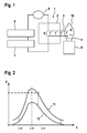
- FIG. 1 schematically shows the structure of the sensor 1.
- the sensor 1 has a housing 2, in which at least a first electrode 3 and a second electrode 4 are provided.
- the arrangement in the housing 2, the first and the second electrode 3, 4 a defined distance 5 from each other.
- the sensor 1 may have a voltage source 6 for generating a high voltage.
- the voltage source 6 can generate the two electrodes 3, 4 with a correspondingly high voltage in a test phase, so that an ionization of the air takes place between the electrodes 3, 4.
- a measuring circuit 7 is provided.
- the measuring circuit 7 comprises a current meter 8.
- a voltage can be applied to the electrodes 3, 4.
- the current flowing between the electrodes 3, 4 is measured both during the test phase and during the measuring phase and reported on to the measuring circuit 7.
- the measuring circuit 7 determines a value for the ionization of the gas flame during a measurement phase and a comparison value during a test phase for the sensitivity of the electrodes 3,4, which is used for a calibration of the electrodes 3,4 during the measuring phase.
- FIG. 1 schematically provides a nozzle 9 of a burner of a heating system, which is connected to a gas source and is designed for the discharge of gas and for generating a gas flame 10.
- the nozzle 9 is not supplied with gas, so that no gas flame 10 is generated.
- the test phase is independent of the operation of the heating system.
- a high voltage is applied to the electrodes 3, 4 by means of the voltage source 6.
- the voltage source 6 generates during the test phase, a voltage which may for example be in the range between 500 volts and 50,000 volts. The voltage is correspondingly high, so that without a gas flame 10, a measurable ionization of the atmosphere takes place and the ammeter 8 can measure a test current.
- the flowing test current is measured with the help of the current meter 8.
- the measured test current is forwarded to the measuring circuit 7.
- the value of the test voltage which is applied by the voltage source 6 to the electrodes 3, 4 during the test phase is preferably transmitted to the measuring circuit 7.
- the measuring circuit 7 can also control the voltage source 6 and the value of the voltage.
- the current meter 8 can detect a time increase of the test current and a maximum test current and forward it to the measuring circuit 7.
- the voltage source 6 can apply different test voltages to the electrodes 3, 4 during the test phase.
- a predetermined test voltage profile with, for example, increasing and / or decreasing values from the voltage source can be applied to the electrodes during the test phase.
- the test voltage can be varied in height so that not only a single test current value, but several test current values for different test current voltages can be detected.
- the test current and / or the time increase of the test current and / or a maximum value for the test current and / or the corresponding voltages of the voltage source can be used by the measuring circuit 7 to provide a comparison value, in particular a characteristic for calibrating the measuring sensitivity of the electrodes during the test Determine measuring phase.
- a measuring phase for example, a measuring voltage is generated between the electrodes 3, 4 by means of the voltage source 6 or by means of the further voltage source.
- the measuring voltage is lower than the test voltage.
- the measuring voltage is for example in the range between 5 and 100 volts.
- a gas flame 10 is generated by the nozzle 9 during the measuring phase and at the same time a measuring current is detected by means of the current meter 8 and transmitted to the measuring circuit 7.
- the measuring circuit 7 determines a value for the ionization of the gas flame, in particular a ⁇ value of the gas flame, depending on the measured measuring current and the measured test current or on the determined comparison value and / or the determined characteristic curve.
- the value for the ionization is output from the measuring circuit 7 and can be used for example for a diagnosis of the quality of the combustion and / or for a control of the combustion, in particular for a control of the mixing ratio of air and gas.
- FIG. 2 shows a schematic representation of a diagram for two characteristic curves 11, 12 of the sensor 1 during a measurement of the ionization of a gas flame.
- Current values are microampere ( ⁇ A) along the y-axis and lambda values for the gas flame are plotted along the x-axis.
- a lambda value of less than 1 means a lack of air during combustion.
- a lambda value greater than 1 means an excess of air.
- the characteristics define a relationship between a current flowing between the electrodes 3, 4 and an ionization of the gas flame, for example a lambda value.
- the first characteristic 11 corresponds to new electrodes 3, 4. During the operation of the sensor 1, the electrodes 3, 4 are subject to aging.
- Aging can be influenced, for example, by soiling of the electrodes and / or damage to the electrodes.
- the sensitivity of the electrodes changes from the first characteristic curve 11 with increasing operating time in the direction of the second characteristic curve 12.
- the second characteristic curve 12 corresponds to a sensor 1 at the end of the service life.
- the characteristic curves can be stored in a memory of the measuring circuit. If predetermined characteristic curves are stored, then the stored characteristic curves can be assigned to different test currents or comparison values. Thus, depending on the measured test current and / or depending on the determined comparison value, the measuring circuit can select one of the stored characteristic curves in order to use the measured measuring current to obtain a value for the ionization to determine the gas flame. Thus, a precise statement about the ionization of the gases in the gas flame can be made during the measuring phase depending on the measured measuring current.
- a characteristic is determined as a function of the test currents which are detected during the test phase. For this purpose, corresponding methods and calculation methods are stored in the measuring circuit 7.
- calculation formulas may be stored in the memory of the measuring circuit, with which a corresponding value for ionization of the gas flame, in particular a ⁇ value can be calculated depending on a measured test current at a fixed test voltage and depending on a specific measuring current during the measuring phase.
- the described sensor and the method described can be used in particular for heating systems for hot water, in order to be able to set low NO x values during combustion. Especially with hot water heaters, it is advantageous if the calibration of the sensor can be performed automatically without the execution of test burns.
Landscapes
- Chemical & Material Sciences (AREA)
- General Health & Medical Sciences (AREA)
- Life Sciences & Earth Sciences (AREA)
- Health & Medical Sciences (AREA)
- Analytical Chemistry (AREA)
- Biochemistry (AREA)
- Physics & Mathematics (AREA)
- General Physics & Mathematics (AREA)
- Immunology (AREA)
- Pathology (AREA)
- Chemical Kinetics & Catalysis (AREA)
- Electrochemistry (AREA)
- Other Investigation Or Analysis Of Materials By Electrical Means (AREA)
Applications Claiming Priority (1)
| Application Number | Priority Date | Filing Date | Title |
|---|---|---|---|
| DE201310222675 DE102013222675A1 (de) | 2013-11-07 | 2013-11-07 | Ionisationssensor |
Publications (2)
| Publication Number | Publication Date |
|---|---|
| EP2871473A1 true EP2871473A1 (fr) | 2015-05-13 |
| EP2871473B1 EP2871473B1 (fr) | 2020-07-08 |
Family
ID=51584999
Family Applications (1)
| Application Number | Title | Priority Date | Filing Date |
|---|---|---|---|
| EP14185687.2A Active EP2871473B1 (fr) | 2013-11-07 | 2014-09-22 | Capteur d'ionisation |
Country Status (4)
| Country | Link |
|---|---|
| EP (1) | EP2871473B1 (fr) |
| DE (1) | DE102013222675A1 (fr) |
| ES (1) | ES2820726T3 (fr) |
| PT (1) | PT2871473T (fr) |
Citations (4)
| Publication number | Priority date | Publication date | Assignee | Title |
|---|---|---|---|---|
| DE2323927A1 (de) * | 1972-05-15 | 1974-02-14 | Ceskoslovenska Akademie Ved | Ionisationsdetektor fuer chromatographische analyse |
| EP1154202A2 (fr) * | 2000-05-12 | 2001-11-14 | Siemens Building Technologies AG | Dispositif de commmande pour un brûleur |
| DE202005003642U1 (de) * | 2005-03-03 | 2005-05-25 | Schütt Labortechnik GmbH | Laborgasbrenner |
| DE102010055567A1 (de) * | 2010-12-21 | 2012-06-21 | Robert Bosch Gmbh | Verfahren zur Stabilisierung eines Betriebsverhaltens eines Gasgebläsebrenners |
-
2013
- 2013-11-07 DE DE201310222675 patent/DE102013222675A1/de not_active Ceased
-
2014
- 2014-09-22 PT PT141856872T patent/PT2871473T/pt unknown
- 2014-09-22 ES ES14185687T patent/ES2820726T3/es active Active
- 2014-09-22 EP EP14185687.2A patent/EP2871473B1/fr active Active
Patent Citations (4)
| Publication number | Priority date | Publication date | Assignee | Title |
|---|---|---|---|---|
| DE2323927A1 (de) * | 1972-05-15 | 1974-02-14 | Ceskoslovenska Akademie Ved | Ionisationsdetektor fuer chromatographische analyse |
| EP1154202A2 (fr) * | 2000-05-12 | 2001-11-14 | Siemens Building Technologies AG | Dispositif de commmande pour un brûleur |
| DE202005003642U1 (de) * | 2005-03-03 | 2005-05-25 | Schütt Labortechnik GmbH | Laborgasbrenner |
| DE102010055567A1 (de) * | 2010-12-21 | 2012-06-21 | Robert Bosch Gmbh | Verfahren zur Stabilisierung eines Betriebsverhaltens eines Gasgebläsebrenners |
Also Published As
| Publication number | Publication date |
|---|---|
| EP2871473B1 (fr) | 2020-07-08 |
| ES2820726T3 (es) | 2021-04-22 |
| DE102013222675A1 (de) | 2015-05-07 |
| PT2871473T (pt) | 2020-08-20 |
Similar Documents
| Publication | Publication Date | Title |
|---|---|---|
| EP1828682B1 (fr) | Procede et dispositif pour influencer des processus de combustion | |
| DE102015205971B4 (de) | Verfahren zum Betreiben einer Sonde | |
| DE102019002274A1 (de) | Gassensor und verfahren zum steuern eines gassensors | |
| DE102012204981A1 (de) | Gaserfassungs-Vorrichtung und Gaserfassungs-Verfahren | |
| EP3775865A1 (fr) | Détecteur à ionisation de flamme et procédé d'analyse d'un gaz de mesure contenant de l'oxygène | |
| DE102012213068A1 (de) | Verfahren und Fehlersimulator zur Überprüfung der Fehlererkennung eines Steuergerätes | |
| EP4127691A1 (fr) | Procédé de détermination d'un paramètre d'état d'un capteur de gaz d'échappement | |
| EP3825610B1 (fr) | Procédé et dispositif de mesure de la valeur lambda dans un bruleur à combustion des fossiles, en particulier pour une installation de chauffage et/ou d'eau sanitaire | |
| DE102014219134A1 (de) | Gaskonzentrationsdetektor | |
| DE102013202260A1 (de) | Verfahren und Vorrichtung zur Überwachung eines mehrzelligen Abgassensors | |
| EP2871473B1 (fr) | Capteur d'ionisation | |
| DE102014226922A1 (de) | Verfahren zur Diagnose von Verbindungsleitungen und Auswertevorrichtung zur Durchführung des Verfahrens | |
| DE2457650A1 (de) | Einrichtung zur ueberpruefung von gasen | |
| EP4023941B1 (fr) | Agencements et procédé de mesure d'une ionisation dans une chambre de combustion d'un brûleur à prémélange | |
| DE102009057121A1 (de) | Verfahren zur qualitativen Überwachung und Regelung des Verbrennungszustandes eines Heizkesselsystems mittels eines Ionisationsflammenwächters | |
| EP3869099B1 (fr) | Procédé, dispositif, et produit logiciel de régulation d'un mélange gaz-air de combustion dans un appareil de chauffage à puissance variable | |
| DE102018123120A1 (de) | Sensorsteuerungsvorrichtung | |
| DE102005024763B3 (de) | Heizgerät und Verfahren zum Steuern eines Heizgerätes | |
| DE102013216595A1 (de) | Verfahren und Vorrichtung zur Korrektur einer Kennlinie einer Lambdasonde | |
| DE102018219567A1 (de) | Verfahren zum Erkennen einer Anpassungsnotwendigkeit eines Kompensationsfaktors eines amperometrischen Sensors und amperometrischer Sensor | |
| DE102013220756A1 (de) | Verfahren zur Bestimmung der Konzentration einer Gaskomponente in einem Gasgemisch | |
| EP1559888B1 (fr) | Méthode et dispositif pour déterminer au moins un paramètre de combustion pendant le processus de combustion | |
| DE102011082641A1 (de) | Verfahren und Vorrichtung zur Regelstreckenmodifikation | |
| DE102011017015B4 (de) | Verfahren zum Betreiben einer Lambdasonde | |
| DE102010002458A1 (de) | Abgassonde |
Legal Events
| Date | Code | Title | Description |
|---|---|---|---|
| PUAI | Public reference made under article 153(3) epc to a published international application that has entered the european phase |
Free format text: ORIGINAL CODE: 0009012 |
|
| 17P | Request for examination filed |
Effective date: 20140922 |
|
| AK | Designated contracting states |
Kind code of ref document: A1 Designated state(s): AL AT BE BG CH CY CZ DE DK EE ES FI FR GB GR HR HU IE IS IT LI LT LU LV MC MK MT NL NO PL PT RO RS SE SI SK SM TR |
|
| AX | Request for extension of the european patent |
Extension state: BA ME |
|
| R17P | Request for examination filed (corrected) |
Effective date: 20151113 |
|
| RBV | Designated contracting states (corrected) |
Designated state(s): AL AT BE BG CH CY CZ DE DK EE ES FI FR GB GR HR HU IE IS IT LI LT LU LV MC MK MT NL NO PL PT RO RS SE SI SK SM TR |
|
| STAA | Information on the status of an ep patent application or granted ep patent |
Free format text: STATUS: EXAMINATION IS IN PROGRESS |
|
| 17Q | First examination report despatched |
Effective date: 20190725 |
|
| GRAP | Despatch of communication of intention to grant a patent |
Free format text: ORIGINAL CODE: EPIDOSNIGR1 |
|
| STAA | Information on the status of an ep patent application or granted ep patent |
Free format text: STATUS: GRANT OF PATENT IS INTENDED |
|
| RIC1 | Information provided on ipc code assigned before grant |
Ipc: F23D 14/46 20060101ALN20200123BHEP Ipc: G01N 30/68 20060101ALI20200123BHEP Ipc: G01N 27/62 20060101AFI20200123BHEP Ipc: F23N 5/12 20060101ALN20200123BHEP |
|
| RIC1 | Information provided on ipc code assigned before grant |
Ipc: F23N 5/12 20060101ALN20200203BHEP Ipc: G01N 30/68 20060101ALI20200203BHEP Ipc: G01N 27/62 20060101AFI20200203BHEP Ipc: F23D 14/46 20060101ALN20200203BHEP |
|
| INTG | Intention to grant announced |
Effective date: 20200219 |
|
| RAP1 | Party data changed (applicant data changed or rights of an application transferred) |
Owner name: ROBERT BOSCH GMBH |
|
| GRAS | Grant fee paid |
Free format text: ORIGINAL CODE: EPIDOSNIGR3 |
|
| GRAA | (expected) grant |
Free format text: ORIGINAL CODE: 0009210 |
|
| STAA | Information on the status of an ep patent application or granted ep patent |
Free format text: STATUS: THE PATENT HAS BEEN GRANTED |
|
| AK | Designated contracting states |
Kind code of ref document: B1 Designated state(s): AL AT BE BG CH CY CZ DE DK EE ES FI FR GB GR HR HU IE IS IT LI LT LU LV MC MK MT NL NO PL PT RO RS SE SI SK SM TR |
|
| REG | Reference to a national code |
Ref country code: AT Ref legal event code: REF Ref document number: 1289004 Country of ref document: AT Kind code of ref document: T Effective date: 20200715 Ref country code: CH Ref legal event code: EP |
|
| REG | Reference to a national code |
Ref country code: DE Ref legal event code: R096 Ref document number: 502014014411 Country of ref document: DE |
|
| REG | Reference to a national code |
Ref country code: IE Ref legal event code: FG4D Free format text: LANGUAGE OF EP DOCUMENT: GERMAN |
|
| REG | Reference to a national code |
Ref country code: PT Ref legal event code: SC4A Ref document number: 2871473 Country of ref document: PT Date of ref document: 20200820 Kind code of ref document: T Free format text: AVAILABILITY OF NATIONAL TRANSLATION Effective date: 20200805 |
|
| REG | Reference to a national code |
Ref country code: LT Ref legal event code: MG4D |
|
| REG | Reference to a national code |
Ref country code: NL Ref legal event code: MP Effective date: 20200708 |
|
| PG25 | Lapsed in a contracting state [announced via postgrant information from national office to epo] |
Ref country code: NO Free format text: LAPSE BECAUSE OF FAILURE TO SUBMIT A TRANSLATION OF THE DESCRIPTION OR TO PAY THE FEE WITHIN THE PRESCRIBED TIME-LIMIT Effective date: 20201008 Ref country code: FI Free format text: LAPSE BECAUSE OF FAILURE TO SUBMIT A TRANSLATION OF THE DESCRIPTION OR TO PAY THE FEE WITHIN THE PRESCRIBED TIME-LIMIT Effective date: 20200708 Ref country code: LT Free format text: LAPSE BECAUSE OF FAILURE TO SUBMIT A TRANSLATION OF THE DESCRIPTION OR TO PAY THE FEE WITHIN THE PRESCRIBED TIME-LIMIT Effective date: 20200708 Ref country code: HR Free format text: LAPSE BECAUSE OF FAILURE TO SUBMIT A TRANSLATION OF THE DESCRIPTION OR TO PAY THE FEE WITHIN THE PRESCRIBED TIME-LIMIT Effective date: 20200708 Ref country code: SE Free format text: LAPSE BECAUSE OF FAILURE TO SUBMIT A TRANSLATION OF THE DESCRIPTION OR TO PAY THE FEE WITHIN THE PRESCRIBED TIME-LIMIT Effective date: 20200708 Ref country code: BG Free format text: LAPSE BECAUSE OF FAILURE TO SUBMIT A TRANSLATION OF THE DESCRIPTION OR TO PAY THE FEE WITHIN THE PRESCRIBED TIME-LIMIT Effective date: 20201008 Ref country code: GR Free format text: LAPSE BECAUSE OF FAILURE TO SUBMIT A TRANSLATION OF THE DESCRIPTION OR TO PAY THE FEE WITHIN THE PRESCRIBED TIME-LIMIT Effective date: 20201009 |
|
| PG25 | Lapsed in a contracting state [announced via postgrant information from national office to epo] |
Ref country code: IS Free format text: LAPSE BECAUSE OF FAILURE TO SUBMIT A TRANSLATION OF THE DESCRIPTION OR TO PAY THE FEE WITHIN THE PRESCRIBED TIME-LIMIT Effective date: 20201108 Ref country code: LV Free format text: LAPSE BECAUSE OF FAILURE TO SUBMIT A TRANSLATION OF THE DESCRIPTION OR TO PAY THE FEE WITHIN THE PRESCRIBED TIME-LIMIT Effective date: 20200708 Ref country code: RS Free format text: LAPSE BECAUSE OF FAILURE TO SUBMIT A TRANSLATION OF THE DESCRIPTION OR TO PAY THE FEE WITHIN THE PRESCRIBED TIME-LIMIT Effective date: 20200708 Ref country code: PL Free format text: LAPSE BECAUSE OF FAILURE TO SUBMIT A TRANSLATION OF THE DESCRIPTION OR TO PAY THE FEE WITHIN THE PRESCRIBED TIME-LIMIT Effective date: 20200708 |
|
| PG25 | Lapsed in a contracting state [announced via postgrant information from national office to epo] |
Ref country code: NL Free format text: LAPSE BECAUSE OF FAILURE TO SUBMIT A TRANSLATION OF THE DESCRIPTION OR TO PAY THE FEE WITHIN THE PRESCRIBED TIME-LIMIT Effective date: 20200708 |
|
| REG | Reference to a national code |
Ref country code: DE Ref legal event code: R097 Ref document number: 502014014411 Country of ref document: DE |
|
| REG | Reference to a national code |
Ref country code: ES Ref legal event code: FG2A Ref document number: 2820726 Country of ref document: ES Kind code of ref document: T3 Effective date: 20210422 |
|
| PG25 | Lapsed in a contracting state [announced via postgrant information from national office to epo] |
Ref country code: CZ Free format text: LAPSE BECAUSE OF FAILURE TO SUBMIT A TRANSLATION OF THE DESCRIPTION OR TO PAY THE FEE WITHIN THE PRESCRIBED TIME-LIMIT Effective date: 20200708 Ref country code: EE Free format text: LAPSE BECAUSE OF FAILURE TO SUBMIT A TRANSLATION OF THE DESCRIPTION OR TO PAY THE FEE WITHIN THE PRESCRIBED TIME-LIMIT Effective date: 20200708 Ref country code: DK Free format text: LAPSE BECAUSE OF FAILURE TO SUBMIT A TRANSLATION OF THE DESCRIPTION OR TO PAY THE FEE WITHIN THE PRESCRIBED TIME-LIMIT Effective date: 20200708 Ref country code: IT Free format text: LAPSE BECAUSE OF FAILURE TO SUBMIT A TRANSLATION OF THE DESCRIPTION OR TO PAY THE FEE WITHIN THE PRESCRIBED TIME-LIMIT Effective date: 20200708 Ref country code: SM Free format text: LAPSE BECAUSE OF FAILURE TO SUBMIT A TRANSLATION OF THE DESCRIPTION OR TO PAY THE FEE WITHIN THE PRESCRIBED TIME-LIMIT Effective date: 20200708 Ref country code: RO Free format text: LAPSE BECAUSE OF FAILURE TO SUBMIT A TRANSLATION OF THE DESCRIPTION OR TO PAY THE FEE WITHIN THE PRESCRIBED TIME-LIMIT Effective date: 20200708 Ref country code: MC Free format text: LAPSE BECAUSE OF FAILURE TO SUBMIT A TRANSLATION OF THE DESCRIPTION OR TO PAY THE FEE WITHIN THE PRESCRIBED TIME-LIMIT Effective date: 20200708 |
|
| REG | Reference to a national code |
Ref country code: CH Ref legal event code: PL |
|
| PLBE | No opposition filed within time limit |
Free format text: ORIGINAL CODE: 0009261 |
|
| STAA | Information on the status of an ep patent application or granted ep patent |
Free format text: STATUS: NO OPPOSITION FILED WITHIN TIME LIMIT |
|
| PG25 | Lapsed in a contracting state [announced via postgrant information from national office to epo] |
Ref country code: AL Free format text: LAPSE BECAUSE OF FAILURE TO SUBMIT A TRANSLATION OF THE DESCRIPTION OR TO PAY THE FEE WITHIN THE PRESCRIBED TIME-LIMIT Effective date: 20200708 |
|
| 26N | No opposition filed |
Effective date: 20210409 |
|
| REG | Reference to a national code |
Ref country code: BE Ref legal event code: MM Effective date: 20200930 |
|
| GBPC | Gb: european patent ceased through non-payment of renewal fee |
Effective date: 20201008 |
|
| PG25 | Lapsed in a contracting state [announced via postgrant information from national office to epo] |
Ref country code: SK Free format text: LAPSE BECAUSE OF FAILURE TO SUBMIT A TRANSLATION OF THE DESCRIPTION OR TO PAY THE FEE WITHIN THE PRESCRIBED TIME-LIMIT Effective date: 20200708 Ref country code: LU Free format text: LAPSE BECAUSE OF NON-PAYMENT OF DUE FEES Effective date: 20200922 |
|
| PG25 | Lapsed in a contracting state [announced via postgrant information from national office to epo] |
Ref country code: FR Free format text: LAPSE BECAUSE OF NON-PAYMENT OF DUE FEES Effective date: 20200930 |
|
| PG25 | Lapsed in a contracting state [announced via postgrant information from national office to epo] |
Ref country code: SI Free format text: LAPSE BECAUSE OF FAILURE TO SUBMIT A TRANSLATION OF THE DESCRIPTION OR TO PAY THE FEE WITHIN THE PRESCRIBED TIME-LIMIT Effective date: 20200708 Ref country code: LI Free format text: LAPSE BECAUSE OF NON-PAYMENT OF DUE FEES Effective date: 20200930 Ref country code: IE Free format text: LAPSE BECAUSE OF NON-PAYMENT OF DUE FEES Effective date: 20200922 Ref country code: GB Free format text: LAPSE BECAUSE OF NON-PAYMENT OF DUE FEES Effective date: 20201008 Ref country code: CH Free format text: LAPSE BECAUSE OF NON-PAYMENT OF DUE FEES Effective date: 20200930 Ref country code: BE Free format text: LAPSE BECAUSE OF NON-PAYMENT OF DUE FEES Effective date: 20200930 |
|
| REG | Reference to a national code |
Ref country code: AT Ref legal event code: MM01 Ref document number: 1289004 Country of ref document: AT Kind code of ref document: T Effective date: 20200922 |
|
| PG25 | Lapsed in a contracting state [announced via postgrant information from national office to epo] |
Ref country code: AT Free format text: LAPSE BECAUSE OF NON-PAYMENT OF DUE FEES Effective date: 20200922 |
|
| PG25 | Lapsed in a contracting state [announced via postgrant information from national office to epo] |
Ref country code: TR Free format text: LAPSE BECAUSE OF FAILURE TO SUBMIT A TRANSLATION OF THE DESCRIPTION OR TO PAY THE FEE WITHIN THE PRESCRIBED TIME-LIMIT Effective date: 20200708 Ref country code: MT Free format text: LAPSE BECAUSE OF FAILURE TO SUBMIT A TRANSLATION OF THE DESCRIPTION OR TO PAY THE FEE WITHIN THE PRESCRIBED TIME-LIMIT Effective date: 20200708 Ref country code: CY Free format text: LAPSE BECAUSE OF FAILURE TO SUBMIT A TRANSLATION OF THE DESCRIPTION OR TO PAY THE FEE WITHIN THE PRESCRIBED TIME-LIMIT Effective date: 20200708 |
|
| PG25 | Lapsed in a contracting state [announced via postgrant information from national office to epo] |
Ref country code: MK Free format text: LAPSE BECAUSE OF FAILURE TO SUBMIT A TRANSLATION OF THE DESCRIPTION OR TO PAY THE FEE WITHIN THE PRESCRIBED TIME-LIMIT Effective date: 20200708 |
|
| PGFP | Annual fee paid to national office [announced via postgrant information from national office to epo] |
Ref country code: PT Payment date: 20250910 Year of fee payment: 12 |
|
| PGFP | Annual fee paid to national office [announced via postgrant information from national office to epo] |
Ref country code: DE Payment date: 20251121 Year of fee payment: 12 |
|
| PGFP | Annual fee paid to national office [announced via postgrant information from national office to epo] |
Ref country code: ES Payment date: 20251020 Year of fee payment: 12 |