EP2872068B1 - Applicateur destiné à l'application, en particulier à commande manuelle, d'un matériau composite photo-durcissable, et agencement d'un moyen d'éclairage sur l'applicateur - Google Patents
Applicateur destiné à l'application, en particulier à commande manuelle, d'un matériau composite photo-durcissable, et agencement d'un moyen d'éclairage sur l'applicateur Download PDFInfo
- Publication number
- EP2872068B1 EP2872068B1 EP13783238.2A EP13783238A EP2872068B1 EP 2872068 B1 EP2872068 B1 EP 2872068B1 EP 13783238 A EP13783238 A EP 13783238A EP 2872068 B1 EP2872068 B1 EP 2872068B1
- Authority
- EP
- European Patent Office
- Prior art keywords
- applicator
- reservoir
- led
- light
- outlet opening
- Prior art date
- Legal status (The legal status is an assumption and is not a legal conclusion. Google has not performed a legal analysis and makes no representation as to the accuracy of the status listed.)
- Active
Links
Images



Classifications
-
- B—PERFORMING OPERATIONS; TRANSPORTING
- B05—SPRAYING OR ATOMISING IN GENERAL; APPLYING FLUENT MATERIALS TO SURFACES, IN GENERAL
- B05C—APPARATUS FOR APPLYING FLUENT MATERIALS TO SURFACES, IN GENERAL
- B05C17/00—Hand tools or apparatus using hand held tools, for applying liquids or other fluent materials to, for spreading applied liquids or other fluent materials on, or for partially removing applied liquids or other fluent materials from, surfaces
- B05C17/005—Hand tools or apparatus using hand held tools, for applying liquids or other fluent materials to, for spreading applied liquids or other fluent materials on, or for partially removing applied liquids or other fluent materials from, surfaces for discharging material from a reservoir or container located in or on the hand tool through an outlet orifice by pressure without using surface contacting members like pads or brushes
- B05C17/0052—Accessories therefor
-
- B—PERFORMING OPERATIONS; TRANSPORTING
- B05—SPRAYING OR ATOMISING IN GENERAL; APPLYING FLUENT MATERIALS TO SURFACES, IN GENERAL
- B05C—APPARATUS FOR APPLYING FLUENT MATERIALS TO SURFACES, IN GENERAL
- B05C1/00—Apparatus in which liquid or other fluent material is applied to the surface of the work by contact with a member carrying the liquid or other fluent material, e.g. a porous member loaded with a liquid to be applied as a coating
- B05C1/04—Apparatus in which liquid or other fluent material is applied to the surface of the work by contact with a member carrying the liquid or other fluent material, e.g. a porous member loaded with a liquid to be applied as a coating for applying liquid or other fluent material to work of indefinite length
- B05C1/06—Apparatus in which liquid or other fluent material is applied to the surface of the work by contact with a member carrying the liquid or other fluent material, e.g. a porous member loaded with a liquid to be applied as a coating for applying liquid or other fluent material to work of indefinite length by rubbing contact, e.g. by brushes, by pads
-
- B—PERFORMING OPERATIONS; TRANSPORTING
- B05—SPRAYING OR ATOMISING IN GENERAL; APPLYING FLUENT MATERIALS TO SURFACES, IN GENERAL
- B05C—APPARATUS FOR APPLYING FLUENT MATERIALS TO SURFACES, IN GENERAL
- B05C17/00—Hand tools or apparatus using hand held tools, for applying liquids or other fluent materials to, for spreading applied liquids or other fluent materials on, or for partially removing applied liquids or other fluent materials from, surfaces
-
- B—PERFORMING OPERATIONS; TRANSPORTING
- B05—SPRAYING OR ATOMISING IN GENERAL; APPLYING FLUENT MATERIALS TO SURFACES, IN GENERAL
- B05C—APPARATUS FOR APPLYING FLUENT MATERIALS TO SURFACES, IN GENERAL
- B05C17/00—Hand tools or apparatus using hand held tools, for applying liquids or other fluent materials to, for spreading applied liquids or other fluent materials on, or for partially removing applied liquids or other fluent materials from, surfaces
- B05C17/005—Hand tools or apparatus using hand held tools, for applying liquids or other fluent materials to, for spreading applied liquids or other fluent materials on, or for partially removing applied liquids or other fluent materials from, surfaces for discharging material from a reservoir or container located in or on the hand tool through an outlet orifice by pressure without using surface contacting members like pads or brushes
- B05C17/00583—Hand tools or apparatus using hand held tools, for applying liquids or other fluent materials to, for spreading applied liquids or other fluent materials on, or for partially removing applied liquids or other fluent materials from, surfaces for discharging material from a reservoir or container located in or on the hand tool through an outlet orifice by pressure without using surface contacting members like pads or brushes the container for the material to be dispensed being deformable
-
- F—MECHANICAL ENGINEERING; LIGHTING; HEATING; WEAPONS; BLASTING
- F21—LIGHTING
- F21K—NON-ELECTRIC LIGHT SOURCES USING LUMINESCENCE; LIGHT SOURCES USING ELECTROCHEMILUMINESCENCE; LIGHT SOURCES USING CHARGES OF COMBUSTIBLE MATERIAL; LIGHT SOURCES USING SEMICONDUCTOR DEVICES AS LIGHT-GENERATING ELEMENTS; LIGHT SOURCES NOT OTHERWISE PROVIDED FOR
- F21K9/00—Light sources using semiconductor devices as light-generating elements, e.g. using light-emitting diodes [LED] or lasers
- F21K9/20—Light sources comprising attachment means
-
- F—MECHANICAL ENGINEERING; LIGHTING; HEATING; WEAPONS; BLASTING
- F21—LIGHTING
- F21K—NON-ELECTRIC LIGHT SOURCES USING LUMINESCENCE; LIGHT SOURCES USING ELECTROCHEMILUMINESCENCE; LIGHT SOURCES USING CHARGES OF COMBUSTIBLE MATERIAL; LIGHT SOURCES USING SEMICONDUCTOR DEVICES AS LIGHT-GENERATING ELEMENTS; LIGHT SOURCES NOT OTHERWISE PROVIDED FOR
- F21K9/00—Light sources using semiconductor devices as light-generating elements, e.g. using light-emitting diodes [LED] or lasers
- F21K9/60—Optical arrangements integrated in the light source, e.g. for improving the colour rendering index or the light extraction
- F21K9/61—Optical arrangements integrated in the light source, e.g. for improving the colour rendering index or the light extraction using light guides
-
- F—MECHANICAL ENGINEERING; LIGHTING; HEATING; WEAPONS; BLASTING
- F21—LIGHTING
- F21V—FUNCTIONAL FEATURES OR DETAILS OF LIGHTING DEVICES OR SYSTEMS THEREOF; STRUCTURAL COMBINATIONS OF LIGHTING DEVICES WITH OTHER ARTICLES, NOT OTHERWISE PROVIDED FOR
- F21V21/00—Supporting, suspending, or attaching arrangements for lighting devices; Hand grips
- F21V21/08—Devices for easy attachment to any desired place, e.g. clip, clamp, magnet
- F21V21/088—Clips; Clamps
Definitions
- the present invention relates to an applicator for the particularly hand-controlled application of a light-curing composite material according to the preamble of the first claim claim 1 and an arrangement of a light source on the applicator.
- an applicator materials of different viscosities are dosed for different purposes.
- the materials can be liquid or viscous.
- the applicator can be operated manually depending on the application and purpose.
- hot glue guns are known, according to DE 102 17 306 A1 may be provided with a lighting for illuminating the work area.
- the curing of the dispensed adhesive takes a long time.
- Hand tools for dispensing and mixing viscous liquids are also known, which are used, for example, in the dental sector.
- Such a solution is in DE 199 35 292 A1 described.
- a light guide is provided for illuminating a gun-like handset, which is connectable via a coupling with a source.
- the light guide is provided with a rotatable optics, which focuses the light on the treatment area.
- a system comprising an application device for applying liquids to a surface, in the form of an inking roller or spray gun, onto which the liquid can be applied from a working region, is disclosed in US Pat DE 10 2007 060 247 A1 described.
- the surface 20 is selectively illuminated by means of a lighting unit, which causes a contrast between coated and uncoated surfaces.
- the aforementioned solutions are not intended for the application of light-curing material and the lighting means are therefore not intended and also not suitable to cure the discharged material.
- a stick-type dispenser for applying a liquid rust converter having a liquid dispensing part and a cap detachably mountable on the dispensing part.
- the cap has an abrasive outer surface that allows you to remove loose paint and rust from a surface onto which the rust converter is to be applied.
- the dispensing member includes elastic walls of polymeric material enclosing an elongate container for holding a reservoir of the rust converter, and a dispensing tip of polymeric material having a housing attached to the reservoir having a passage communicating with an opening leading into the reservoir stands.
- a valve member in the housing may be tight with its periphery to an inner surface of the same, the one end of the passage forms, with a tip through the outlet end of the passage, when the valve member is close to this inner surface.
- a biasing means presses the valve member into the sealed seat on the inner surface forming the end portion of the passage and permits movement of the valve member to an open position spaced from the inner surface for rust converter to flow past.
- the valve element can be brought into its open position by pressing its tip on a surface to be removed from the rust.
- the flow of the rust converter past the open valve element can be intensified by pressing inwards onto the elastic walls forming the reservoir.
- a dispenser adapted to deliver flowing liquid adhesive, either in the form of a film or in the form of a series of small dots or lines, the dispenser having a collapsible container body provided with an outlet in the form of an elongated cylindrical nozzle in DE 89 09 092.6 described.
- the dispenser has a control cap with a coaxial sleeve extending inwardly from the underside of the planar top surface of the control cap and the hole receiving the nozzle.
- the nozzle is provided with a positioning pin which cooperates with a helical groove in the inner surface of the sleeve such that rotation of the control cap by hand in a direction about the longitudinal axis of the nozzle causes the pin to move along the groove towards that end of the nozzle Groove migrates away from the flat top surface of the control cap, thereby retracting the nozzle into the dispenser until the tip of the nozzle no longer projects beyond the flat top surface, rotation in the opposite direction causing the spigot to pass the groove runs toward the end of the groove closer to the planar top surface, thereby causing the tip of the nozzle to protrude beyond the planar top surface of the control cap.
- the base of the nozzle is attached to the walls of the container body via a flexible membrane to allow such movement of the nozzle.
- this surface acts as a spreading or spreading tool so that adhesive emerging from the nozzle can be spread into a film.
- adhesive from the nozzle tip may be in the form of a fine line or in the form of a number of points.
- the structural design of this dispenser is relatively expensive.
- a further disadvantage is that a removable closure cap is required for sealing the dispenser. Even with this solution, a light source is not required, since conventional adhesive and no light-curing material is output.
- a flash device for curing photo-curable materials, a method, and a kit are described. It is thus produced a flash, which can be used in a flexible light guide areas for use.
- the flash device is designed, for example, in the manner of a ballpoint pen, which can be switched on or off by pressing a button.
- the flash device may include a reservoir for receiving photo-curable material disposed in a housing.
- the device can be designed, for example, in the form of a pen with a reservoir for the light-curable material.
- an LED lamp is provided at the opposite end of the outlet opening of the housing. After applying the photo-curable material, the housing must be rotated transversely to its longitudinal axis.
- a set which comprises at least one metering device with light-curing material, which is detachably received in a housing. Furthermore, a light-emitting device for curing the light-curing material in the form of an LED lamp is arranged on the housing. A dosing device for dispensing the light-curing material is detachably connected to the dosing device, wherein the dosing device and / or a dosing channel of the dosing device for dispensing the light-curing material has a releasable closure.
- the metering channel and the light emitting device are configured or provided at two opposite end portions of the set, the housing having at least one aperture for manually controlled metering of the photohardening material and means for releasably receiving the light emitting device.
- the disadvantage here is that the reservoir is additionally encased in the form of the metering device by a housing.
- Another disadvantage of the processing process is that the LED is located at the opposite end of the housing from the dosing channel, since this requires that the set be turned over after the light-curing material has been applied and then the curing process started by actuating the LED. In the two aforementioned solutions, it can happen that the light-curing material is undesirable before it is cured. Furthermore, an insufficiently precise manual pressure regulation can be realized.
- an irradiation device for ultraviolet radiation wherein the irradiation device is designed to be portable.
- the irradiation device is designed in the form of an applicator and has a reservoir in the interior with an outlet opening arranged on an end face of the applicator.
- bulbs for generating the ultraviolet radiation are integrated into the applicator.
- the application unit and the irradiation unit move alternately to and from the housing.
- the application unit moves out of the housing while the irradiation unit is stored in the housing.
- a main switch is surely in an OFF state while special resin is used using the application unit. Therefore, ultraviolet rays are not emitted while special resin is applied.
- the object of the invention is to propose an applicator for hand-controlled application of a light-curing composite material, which has a simple structural design and designed to cure the light-curing material immediately after its application and to provide a lighting device therefor. Furthermore, it should be ensured that a precise manual pressure on the reservoir is ensured to output the hardenable material evenly dosed.
- the applicator according to the invention and the arrangement of a luminous means on the applicator are used for applying a light-curing composite material contained in a reservoir, wherein the applicator has a longitudinal axis and at an anterior end an exit opening for the light-curing material and the applicator for manually controlled application of a manually deformable Reservoir having an output device connected to the reservoir with the outlet opening and conveyed by manual pressure application to the reservoir, the light-curing composite material in the output device and output via the outlet opening and that at least one light source on or in the applicator arranged or connectable to the applicator is that the light of the bulb when it is actuated towards the front end of the applicator brightly on the issued light-curing material and curing it t, wherein the at least one light-emitting means is designed as an LED lamp with one or more LEDs and radiates directly in the direction of the outlet opening of the applicator or that adjoins the light source, a light guide, which emits the light emitted by
- an applicator for applying by means of pressure with the fingers of a light-curing composite material contained in the applicator is thus proposed.
- the LED lamp can be brought from a position fastened to the applicator, in which the LED points away from the outlet opening, into a position fastened to the applicator, in which the LED radiates in the direction of the outlet opening or adjoins an optical conductor which connects through the illuminant / the LED emits light emitted on the material dispensed from the applicator.
- the applicator according to the invention has at least one reservoir.
- the reservoir is prepared, for example, for releasably receiving a snap-in device with integrated LED lamp when using light-curing composite materials, directly on the reservoir behind the closure unit.
- the applicator may comprise a non-releasable closure unit and a receptacle of the closure unit through which the light-curing material is applied or applied.
- the receptacle of the closure unit -particularly or preferably wholly or substantially-is made of a first material or has a first material, to which the reservoir is-or preferably completely or substantially-made from or comprises a second material.
- the second material is different from the first material.
- the inclusion of the closure unit can be made of a plastic or has such.
- the reservoir can form the main component of the applicator and can be produced from a material softer than the receptacle of the closure unit or at least comprise a softer material.
- This embodiment can advantageously contribute or ensure the tightness between the reservoir and the receiving unit of the closure unit as well upon successful elastic deformation of the reservoir, for example when pressure is applied thereto.
- the reservoir may have a wall thickness in a range from 0.4 mm to 1.2 mm, preferably from 0.5 to 0.9 mm, in at least one region thereof and / or in its lateral surface, or in a main region in each case.
- the reservoir can be light-curable material which cures by means of radiation in a range of 300 to 600 nanometers nm, in particular in a range of 395 to 470 nm.
- the reservoir can be made of an opaque material.
- the opaque material is preferably, at least or in particular opaque to a radiation range of 300 to 600 nanometers (nm), in particular in a range of 395 to 470 nm.
- the dispenser has a receptacle attached to the reservoir. and cooperates with a closure unit having the outlet opening.
- a circumferential ring is provided on the preferably insoluble closure unit. The encircling ring serves to shadow the closure unit with respect to the light radiation of the LED lamp. This is intended to prevent hardening of the light-curing plastic on the closure unit and thus also obstruction of the closure unit.
- the closure unit and the LED lamp are designed or provided at the same end region of the reservoir or at opposite end regions.
- the lamp / LED lamp has one or more LEDs.
- a snap device with an integrated / receivable LED lamp can, for example, be arranged releasably or non-detachably on the reservoir or a housing of the applicator.
- the permanent attachment can be done for example by gluing, thermal bonding or the like.
- the reservoir can be prepared accordingly.
- the reservoir comprises a device for releasably receiving the integrated LED light snap device; or there is a device on the housing or the reservoir, in which the LED lamp or the LED housing is einclipbar.
- This device is configured as a snap device in some embodiments of the invention.
- FIGS. 1 to 8 are not the subject of the invention and are merely for better understanding thereof.
- FIG. 1 a variant of a non-inventive dosing / applicator 100 is shown.
- the reservoir 1 comprises a chemical composite material (not visible here).
- the light-curing material is conveyed or pressed into the outlet side not shown here dosing of the output device A and output via the outlet opening 3.1.
- the output device A is firmly connected to the reservoir or designed in one piece with this. It is here a separate cap 4 is provided.
- a dosing tip 3a of the dispenser A, through which leads in this case the metering channel, not shown, with the outlet opening 3.1, is in the reservoir 1 is inserted and connected to this.
- various snap devices or types of threads in the reservoir 1 and the metering tip 3a can be provided.
- the fixation can also be done for example in the form of a press fit or a catch.
- the dosing tip 3a of the dispensing device A can be made of plastic or a metal. Alternatively, it is possible to form the metering tip 3a in one piece with the reservoir 1.
- the reservoir 1 in this embodiment is made of a first material, e.g. a soft polyethylene (for example HDPE high density polyethylene) - or has such.
- the dosing tip is made of a second material - e.g. a harder polymer, but in any case a relative to the first material harder material - designed or has such.
- Both the first and second materials may be selected if a chemical composite that cures by light polymerization is used (or processed, eg, by black or other coating or coloring), preferably, at least or in particular in a light wavelength range of 300 to 600 nanometers (nm) - opaque to the light-curable material of the reservoir 1 and the metering tip 3a to prevent accidental curing by exposure to light.
- the material of the closure cap 4, which is embodied here in the form of a stand closure, is optionally or preferably likewise opaque, in particular in a light wavelength range of 300 to 600 nanometers (nm), in order to prevent the light-curable material from undesired curing before it leaves the outlet opening 3.1 To protect the light.
- the outlet opening 3.1 is closed.
- the locking is preferably done via a snap closure.
- On the Dosierspitze 3a opposite Aufsteckvor holeung 11 may optionally an LED lamp 9, a smoothing device 14 in the manner of a spatula or other Aufsteck-tool are plugged. It is also possible to put an adapter element on the slip-on preparation 11, to which the LED lamp 9 and the smoothing device 14 / the spatula can be fastened.
- the chemical photocurable composite material is cured by irradiation with the light of the LED, in this embodiment by LED light in the light wavelength range between 360 and 470 nanometers (nm).
- This LED light is preferably provided by a commercially available LED lamp 9, which can be detachably attached to the reservoir 1.
- a photo-curing material, or other chemical composite material may be processed prior to curing by UV radiation from the LED lamp or by self-curing, with the flattening device 14 / the attachable spatula.
- the reservoir 1 is elongate, in particular pin-shaped and thus extends along a longitudinal axis L in the X direction. It has an actuating region 16 which has a reduced height H in the Y-direction and is thus formed there in the shape of a trough, so that opposing fingers can grasp this region well and the actuating region can engage in one Preferred direction, here in the Y direction is compressible.
- This design of the actuating portion 16 ensures secure gripping and accurate dosing.
- FIGS. 2 to 4 Another variant of a non-inventive applicator 100 is in the FIGS. 2 to 4 shown.
- the hollow reservoir 1, which receives the light-curing material, has a substantially circular cross section with a diameter D at both ends.
- the output unit A connects to the outlet opening 3.1, at the other end of the LED lamp 9 is arranged, which sits in an LED housing 9.1.
- the dispensing device A is composed here of a closure unit 3 having the outlet opening 3.1 and a receiving unit 13.
- the closure unit 3 forms a rotary closure with which the outlet opening 3.1 can be opened and closed. This is not a cap as in FIG. 1 required.
- the LED housing 9.1 is connected to the reservoir 1 via an annular adapter element 6.
- the LED 9 is switched on or off.
- the cross-section of the reservoir 1 in the Y-direction decreases from the diameter D to a height H (see FIG. FIG. 12 ) and the width increases from the diameter D to a width B (see FIG. FIGS. 2 and 4 ).
- the reservoir 1 is securely gripped and compressed in a preferred direction in the operating region 16, whereby an accurate dosing is possible.
- the thick arrows in the FIGS. 2 and 3 indicate the direction of actuation. From the FIGS.
- FIG. 5 is a partial longitudinal section AA according to FIG. 2 shown in the area of the reduced height H in the operating area 16.
- FIG. 6 again shows the schematic diagram of the side view of an applicator 100, at the reservoir 1, the LED housing 9.1 with the therein arranged LED 9 (and electronics, switches and battery) via an annular adapter element 6, is attached to the end, which the outlet opening of the 3.1 Output device A is opposite.
- the adapter element 6 and the LED housing 9.1 are advantageously removable from the reservoir 1 of the applicator 100.
- the reservoir 1 has for this purpose a diameter-reduced area 8, which serves to receive the adapter element 6, which for applying to the area 8, a first annular element 6.1.
- the adapter element 6 has a diameter-reduced region 6.2 in the direction of the LED housing 9.1, which serves to receive the LED housing 9.1, which engages over the diameter-reduced region 6.2.
- Adapter element 6 and reservoir 1 or LED housing 9.1 and adapter element 6 may optionally be connected to one another via a plug connection, a clip connection, a screw connection, etc., preferably releasably, in which case, of course, the requisite elements required for this purpose must be provided.
- the adapter element 6 is provided in the region of the annular element 6.1 with an internal thread and the diameter-reduced region 8 with a corresponding external thread, so that the adapter element 6 can be screwed onto the reduced-diameter region 8 of the reservoir 1.
- the diameter-reduced region 6.2 of the adapter element 6 preferably has an external thread and the LED housing 9.1 has a corresponding internal thread and can thus be screwed onto the adapter element 6.
- An unspecified paragraph of the adapter element 6 forms a stop for the LED housing 9.1.
- the adapter element 6 furthermore has a transverse wall or a bottom 6.3.
- the adapter element 13 serves to close the second opening 8.2, by means of the screw connection and the wall 13.3. Furthermore, the wall 13.3 can serve as a contact for a switching contact for actuating the LED 5. If the LED housing 3 is slightly spaced via the screw connection to the shoulder / stop, the switching contact is open and the LED 5 is switched off. If the LED housing 3 as in Fig. 6 shown, screwed to the stop of the adapter element 6, the switch contact is closed and the LED 5 lights up.
- the circuit can also be carried out so that the LED 5 is located at the end stop LED housing 3 and is switched off when moving away the LED housing from the adapter element or alternatively, a pressure switch can be used. If a first opening 1.1 and a second opening 1.2 are provided at the two ends of the reservoir 1, the reservoir 1 can be filled after detaching the adapter element from the direction of the second opening 1.2.
- the adapter element can be designed symmetrically and have a thread at both ends, so that no mounting direction for the attachment of the output unit and the adapter element must be observed.
- a diameter reduction with thread not shown here is then also in the direction of the output device A, on which the output device A is screwed, this diameter reduction is then formed substantially as the diameter-reduced region 8. Since no installation direction for fixing the output unit A and the adapter element 6 must be observed due to the symmetrical design and the same end regions of the reservoir, the manufacturing and assembly costs are reduced.
- the reservoir 1 can be connected at any end to the output device A and at the other end with the LED housing.
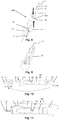
- FIGS. 8 to 11 it is also possible to arrange the reservoir 1 in a housing 20 preferably exchangeable.
- the housing 20 has two opposing recesses 20.1, through which the reservoir 1 is manually compressible, as in FIG. 8 indicated by the thick arrows.
- the output device A is then attached to the outlet opening 3.1.
- the LED 9 with the LED housing 9.1 is clipped in via a snap device 7 and, as indicated by the double arrow, can be removed therefrom and inserted again.
- the LED 9 is switched on and off by means of a pressure switch 23. This is illuminated after applying the lichaushärtenden material on this and cured the material by either the applicator 100 is rotated transversely to its longitudinal axis L or the LED 9 is removed from the snap device 7 and lit on the discharged material.
- FIG. 8 be coupled over the range of the LED 9 with a non-designated plug-in device, a light guide 21, which redirects the light emitted by the LED 9 forward towards the outlet opening 3.1, as in the inventive FIG. 9 is shown schematically. Another variant according to the invention is in FIG. 10 shown.
- a second snap device 7.1 is provided on the housing 20 in the direction of the output unit A, which can be closed by a closure cap 4 here.
- the LED housing 9.1 can now be removed from the snap device 7 and used with the LED 9 facing towards the output unit A in the second snap device 7.1. Now it is possible to shine on the LED 9 during the dispensing of the light-curing material. It is of course also possible immediately in the snap device 7 and in the second snap 7.1 to arrange an LED (with a corresponding LED housing) or to integrate these two LEDs firmly into the housing 1, so that an LED in the direction of the outlet opening 3.1 and an LED lights in the direction away from it.
- FIG. 11 shows a variant of an applicator 100 according to the invention, with a housing 20 and a reservoir 1 housed therein, which as in the FIGS. 8 to 10 on the output unit A opposite end has a snap device 7 for releasably clipping an LED housing.
- the LED housing 9.1 removed from the snap device (clip device) 7 and inserted into a box-like receptacle 7.2, so that the LED 9 adjacent to a light guide 21. This leads from the LED 9 through the receptacle 7.2 and points with its exit-side end on the outlet opening 3.1.
- the LED 9 Upon actuation of a switch (not visible here), the LED 9 is turned on and its emitted light radiates via the light guide 21 to the output through the outlet opening 3.1 material.
- the outlet 3.1 is here closed with a cap 4. It is also possible to integrate the LED 9 in the housing 20 and to lay from this the light guide 21 in the direction of the outlet opening 3.1 and, if necessary, in addition to the snap device 7 to record an LED 9.
- the light guide / the light guide cable is preferably a fiber optic cable.
- Fig. 12 shows a further embodiment of an inventive applicator 100 in a spatial representation with all components.
- the reservoir 1 has a light-curing composite material (not shown here).
- the reservoir 1 is adjoined by an output device A, which is composed of a closure unit 3 having an outlet opening 3.1 and a receiving unit 13.
- the closure unit 3 has on the periphery a shielding ring 15 to protect the photocurable material after exiting the outlet opening 3.1 against accidental curing by the action of light of the LED lamp 9 and thus prevents clogging of existing in the dispensing device A dosing 5 during the curing of the discharged light-curing composite material, when the radiation of the LED lamp, the material of the closure unit 3 can penetrate at least in the region of the outlet opening 3.1.
- the LED lamp 9 is arranged in an LED housing 9.1 and preferably detachably connected via a snap device 7 to the reservoir 1.
- the LED lamp 9 lights when actuated by the shield 15 in an inclined to the longitudinal axis of the applicator angle in the direction of the outlet opening 3.1.
- a switch 23, which is integrated into the LED housing 9.1, serves to switch the LED lamp 9 on and off.
- the closure unit 3 is connected inseparably to the receiving unit 13 via a snap-action thread.
- the receiving unit 13 is connected to the reservoir 1 by means of a screw connection. For this purpose, various types of threads in the reservoir 1 and the receiving unit 13 may be provided. Alternatively, it is possible to realize the connection via a snap connection.
- the fixation can also be done for example in the form of a press fit or a catch.
- the receiving unit 13 and the closure unit 3 may be made of plastic or a metallic material.
- the reservoir 1 is in this embodiment made of a first material, for example a soft polyethylene (for example LDPE low density polyethylene) - or has such.
- the receiving unit 13 is preferably made of a second material - for example, a harder polymer, but in any case a relative to the first material of the reservoir harder material or has such.
- the light-curing material is conveyed or pressed into the output device A.
- the light-curing material enters the closure unit 3 and is conveyed through this by a schematically indicated by dashed dosing 5 through the outlet opening 3.1.
- the LED lamp 9 can be operated so that the output light-curing material is immediately cured. Turning over the applicator 100 to cure the output light-curing adhesive / material can be dispensed with.
- the photocurable composite is cured by light, in this embodiment by LED light in the wavelength range between 395 and 470 nanometers (nm). This LED light is provided by the integrated into the snap device LED lamp 7, which can be detachably or permanently attached to the reservoir 1.
- the reservoir 1 is shown, which has a peripheral Aufsteckvorkung 11, to which a snap device 7 (s. Fig. 1 and 6 ) can be clipped with LED lamp 9 integrated in an LED housing 9.1.
- the reservoir 1 has at one end an opening 1.1 through which exits the light-curing material at peripheral pressure on the reservoir 1 in the output device, not shown here.
- a thread 17 is provided on which the output device (not shown here) can be screwed.
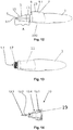
- the receiving unit 13 of the output device A is shown in longitudinal section.
- the receiving unit 13 has a fastening ring 13.1 with an internal thread 19, which can thus be fastened to the reservoir, not shown here, by a screw connection.
- the receiving unit 13 has an external thread 13.4 with snap closure (not visible here).
- the closure unit 3 is formed with a tapered passage opening 3.2, at one end of the outlet opening 3.1 is present.
- an internal thread 3.3 is formed with locking elements, not shown, which is screwed onto the external thread 13.4 and then inextricably locked, wherein the closure unit 3 is still rotatable and corresponding to the pitch of the thread in the longitudinal direction.
- the non-designated inner diameter of the discharge opening 3.1 substantially corresponds to the outer diameter of the massive tip 13.3 of in FIG. 3
- In the assembled state engages in the closed output device A in accordance with the left illustration in FIG. 16 the massive tip 13.3 in the outlet opening 3.1, whereby it is closed and no material can be output.
- FIG. 17 the snap device 7 is shown with the LED 9 and the LED housing 9.1. This is in accordance with the slip-on preparation 11 FIG. 13 attachable.
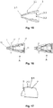
- FIGS. 18 to 20 show an applicator 100 in a schematic representation, on which the LED 9 is integrated in an LED housing 9.1.
- a switch preferably a pressure switch 23 for actuating the LED 9 is present.
- the reservoir 1 the output device A, consisting of receiving unit 13 and closure unit 3, respectively.
- the closure unit 3 is formed in the manner of a rotary closure and has an outlet opening 3.1, which is closed in the closed state by the massive tip 13.3 of the receiving unit ( FIGS. 19 and 20 ) and is released in the open state after rotation of the closure unit 3 by the massive tip 3 ( Fig. 18 ) so that the curable material can escape when the reservoir 1 is compressed by manual operation.
- the closure unit 3 is therefore made of a corresponding opaque plastic or material (eg of metallic material), which prevents the light of the LED lamp 9 from curing the light-curing material before it leaves the outlet opening 3.1.
- the LED housing 9.1 with the receiving unit 13 in one piece, for example by injection molding, formed.
- the closure unit 3 is open. If pressure is exerted on the wall of the reservoir 1, as indicated by the bold arrows, the light-curing material contained therein is conveyed through the opening 1.1 of the reservoir 1 into the receiving unit 13 and the closure unit 3 and can exit through the outlet opening 3.1 (see FIG.
- FIG. 19 shows a gap between the massive tip 13.3 and the outlet opening 3.1. It is according to FIG. 19 also possible to form the LED housing 9.1 to the wall of the reservoir 1 or thus integrally formed or clipped. Another variant shows FIG. 20 , In this, the LED housing 9.1 is arranged in the region of the closure unit 3 or integrally formed therewith.
- a filling opening can be provided in the wall of the reservoir 1. This may be provided at the opposite end of the dispenser A and is according to FIG. 20 closed for example with a detachable end cap 1.3.
- the LED lamp 9 with the LED housing 9.1 can also be arranged between output device A and reservoir 1 (for example by a clamping connection), in which case a corresponding material flow has to be ensured.
- the LED housing 9.1 fastened by a snap connection at least partially surrounds the reservoir 1 and the receiving unit A with the snap device and thus prevents the receiving unit A from inadvertently loosening when it is screwed to the reservoir 1.
- the LED lamp of the applicator can also be screwed by a screw connection to the reservoir or to the output device.
- One or more LEDs are preferably used which generate light in the visible wavelength range. Blue light in the wavelength range from 420 to 490 nm has proved to be particularly advantageous. A big advantage is that the light in the visible wavelength range is harmless to health.
Landscapes
- Engineering & Computer Science (AREA)
- Mechanical Engineering (AREA)
- General Engineering & Computer Science (AREA)
- Physics & Mathematics (AREA)
- Microelectronics & Electronic Packaging (AREA)
- Optics & Photonics (AREA)
- Coating Apparatus (AREA)
- Dental Tools And Instruments Or Auxiliary Dental Instruments (AREA)
Claims (14)
- Applicateur et disposition d'une lampe sur l'applicateur en vue de l'application d'un matériau composite photopolymérisable contenu dans un réservoir (1), dans lesquels l'applicateur (100) possède un axe longitudinal (L) et dans lesquels une extrémité antérieure comporte une ouverture de sortie (3.1) pour le matériau photopolymérisable, l'applicateur présentant, en vue d'une application contrôlée manuellement, un réservoir (1) déformable manuellement, le réservoir (1) étant raccordé à une installation de distribution (A) par l'ouverture de sortie (3.1) et l'application manuelle d'une pression sur le réservoir (1) acheminant le matériau composite photopolymérisable dans l'installation de distribution (A) et le faisant sortir par l'ouverture de sortie (3.1), et dans lesquels au moins une lampe, conçue comme une lampe à DEL (9) avec une ou plusieurs DEL, est disposée sur ou dans l'applicateur (100) ou peut être reliée à l'applicateur (100), caractérisés en ce que l'au moins une lampe est disposée de telle manière que pendant la sortie du matériau photopolymérisable, la lumière de la lampe, lorsque celle-ci est actionnée en direction de l'extrémité antérieure de l'applicateur (100), éclaire le matériau photopolymérisable qui en sort et le polymérise, et en ce que l'au moins une lampe émet directement en direction de l'ouverture de sortie (3.1) de l'applicateur (100) ou en ce qu'un guide d'ondes lumineuses (21) qui amène la lumière émise par la lampe jusqu'au matériau sortant de l'applicateur (100) se raccorde à la lampe.
- Applicateur et disposition selon la revendication 1, caractérisés en ce que la lampe à DEL (9) peut être amenée d'une position fixée sur l'applicateur (100) dans laquelle la DEL est écartée de l'ouverture de sortie à une position fixée sur l'applicateur (100) dans laquelle la DEL émet en direction de l'ouverture de sortie (3.1) ou se raccorde à un guide d'ondes lumineuses (21) qui amène la lumière émise par la lampe/la DEL jusqu'au matériau sortant de l'applicateur (100).
- Applicateur et disposition selon la revendication 1, caractérisés en ce que l'au moins une lampe peut être fixée de façon amovible ou inamovible sur l'applicateur (100).
- Applicateur et disposition selon la revendication 1, caractérisés en ce que le réservoir (1) est disposé dans un boîtier (20) de façon à pouvoir être échangé.
- Applicateur et disposition selon la revendication 4, caractérisés en ce qu'un dispositif dans lequel la lampe à DEL (9) peut être clipsée est prévu sur le boîtier (20) ou le réservoir (1) de l'applicateur (1).
- Applicateur et disposition selon la revendication 1, caractérisés en ce que le boîtier de DEL (9.1) fixé par un assemblage enclenché entoure au moins partiellement le réservoir (1) et l'installation de distribution (A) avec le dispositif d'enclenchement.
- Applicateur et disposition selon la revendication 1, caractérisés en ce que la lampe à DEL (9) émettant en direction de l'ouverture de sortie (3.1) peut être fixée de façon amovible ou inamovible sur le réservoir (1) et/ou sur une installation de distribution (A) qui se raccorde au réservoir (1) au moyen d'une fixation amovible ou inamovible et est disposée dans un boîtier de DEL (9.1) et peut être fixée sur sa circonférence au moyen d'un élément de clip (7) au réservoir (1) et/ou à l'installation de distribution (A) ou entre le réservoir (1) et l'installation de distribution (A).
- Applicateur et disposition selon la revendication 1, caractérisés en ce qu'un boîtier de DEL (9.1) est vissé au réservoir (1) ou à une installation de distribution (A) ou en ce que la lampe à DEL (9) est formée d'un seul tenant sur la circonférence avec son boîtier de DEL (9.1) avec le réservoir (1) ou l'installation de distribution (A) ou moulée par injection sur sa circonférence sur le réservoir (1) ou l'installation de distribution (A).
- Applicateur et disposition selon la revendication 1, caractérisés en ce qu'une installation de distribution (A) présente une unité de logement (13) qui est reliée au réservoir (1) et une unité de fermeture (3) qui présente l'ouverture de sortie (3.1), la lampe à DEL (9) étant fixée ou formée avec un boîtier de DEL (9.1) sur l'unité de logement (13) ou l'unité de fermeture (3).
- Applicateur et disposition selon l'une des revendications 1 à 3 et 7 à 9, caractérisés en ce qu'un écran (15) est disposé entre l'ouverture de sortie (3.1) et la lampe à DEL (9).
- Applicateur et disposition selon la revendication 10, caractérisés en ce que l'écran (15) est formé ou disposé sur le réservoir (1) ou l'installation de distribution (A) ou entre le réservoir (1) et l'installation de distribution (A) ou sur l'unité de fermeture (3) ou sur l'unité de logement (13).
- Applicateur avec une disposition d'une lampe selon l'une des revendications 1 à 11, caractérisé en ce que lorsqu'un guide d'ondes lumineuses est utilisé, celui-ci va de la DEL à l'ouverture de sortie en passant au moins en partie sur l'extérieur le long de l'applicateur ou passe à travers un évidement dans un boîtier de l'applicateur de la DEL jusque près de la zone de sortie du matériau photopolymérisable.
- Applicateur selon l'une des revendications 1 à 12 , caractérisé en ce que la lampe à DEL (9) peut être activée sélectivement au moyen d'un manostat, d'un commutateur à contact ou d'un capteur capacitif et en ce que la lampe à DEL (9) présente au moins une pile pour l'alimentation électrique.
- Applicateur selon l'une des revendications 1 à 13, caractérisé en ce qu'il est prévu une commande électronique de la lampe à DEL (9).
Priority Applications (1)
| Application Number | Priority Date | Filing Date | Title |
|---|---|---|---|
| EP17205533.7A EP3323379B1 (fr) | 2012-07-12 | 2013-07-11 | Applicateur permettant l'application d'une matière composite durcissante à la lumière |
Applications Claiming Priority (2)
| Application Number | Priority Date | Filing Date | Title |
|---|---|---|---|
| DE202012102583U DE202012102583U1 (de) | 2012-07-12 | 2012-07-12 | Dosiereinrichtung für chemisches Verbundmaterial |
| PCT/DE2013/100258 WO2014008894A2 (fr) | 2012-07-12 | 2013-07-11 | Applicateur destiné à l'application, en particulier à commande manuelle, d'un matériau composite photo-durcissable, et agencement d'un moyen d'éclairage sur l'applicateur |
Related Child Applications (2)
| Application Number | Title | Priority Date | Filing Date |
|---|---|---|---|
| EP17205533.7A Division-Into EP3323379B1 (fr) | 2012-07-12 | 2013-07-11 | Applicateur permettant l'application d'une matière composite durcissante à la lumière |
| EP17205533.7A Division EP3323379B1 (fr) | 2012-07-12 | 2013-07-11 | Applicateur permettant l'application d'une matière composite durcissante à la lumière |
Publications (2)
| Publication Number | Publication Date |
|---|---|
| EP2872068A2 EP2872068A2 (fr) | 2015-05-20 |
| EP2872068B1 true EP2872068B1 (fr) | 2019-08-07 |
Family
ID=47321693
Family Applications (2)
| Application Number | Title | Priority Date | Filing Date |
|---|---|---|---|
| EP17205533.7A Active EP3323379B1 (fr) | 2012-07-12 | 2013-07-11 | Applicateur permettant l'application d'une matière composite durcissante à la lumière |
| EP13783238.2A Active EP2872068B1 (fr) | 2012-07-12 | 2013-07-11 | Applicateur destiné à l'application, en particulier à commande manuelle, d'un matériau composite photo-durcissable, et agencement d'un moyen d'éclairage sur l'applicateur |
Family Applications Before (1)
| Application Number | Title | Priority Date | Filing Date |
|---|---|---|---|
| EP17205533.7A Active EP3323379B1 (fr) | 2012-07-12 | 2013-07-11 | Applicateur permettant l'application d'une matière composite durcissante à la lumière |
Country Status (4)
| Country | Link |
|---|---|
| US (1) | US9694383B2 (fr) |
| EP (2) | EP3323379B1 (fr) |
| DE (6) | DE202012102583U1 (fr) |
| WO (1) | WO2014008894A2 (fr) |
Families Citing this family (18)
| Publication number | Priority date | Publication date | Assignee | Title |
|---|---|---|---|---|
| US20170231734A1 (en) * | 2010-09-30 | 2017-08-17 | Dinko Jurcevic | Flashlight Device for Curing Light-Curable Materials, Method and Set |
| EP2823894A1 (fr) * | 2013-07-11 | 2015-01-14 | KDS Holding GmbH | Applicateur destiné à appliquer un matériau composite durcissant sous l'effet de la lumière |
| DE102013107548A1 (de) | 2013-07-16 | 2015-01-22 | Thomas Offermann | Dosierapparat zum handgesteuerten Dosieren eines lichtaushärtenden Materials |
| DE202014103202U1 (de) | 2014-07-11 | 2015-10-13 | Kds Holding Gmbh | Applikator zum Auftragen eines lichtaushärtenden Verbundmaterials |
| EP2977112A1 (fr) * | 2014-07-25 | 2016-01-27 | Sika Technology AG | Crayon d'application |
| DE102014218064A1 (de) * | 2014-09-10 | 2016-03-10 | Henkel Ag & Co. Kgaa | Vorrichtung zur Behandlung von Flecken sowie Verfahren zur Behandlung von Flecken unter Verwendung einer solchen Vorrichtung |
| US10682290B2 (en) | 2015-05-29 | 2020-06-16 | 3M Innovative Properties Company | Kit of parts for conducting a dental impression and retraction process |
| DE102015116994A1 (de) * | 2015-10-06 | 2017-04-06 | Anke Viering | Dosierapparat zum handgesteuerten Dosieren eines lichtaushärtenden Materials |
| DE202016104733U1 (de) * | 2016-08-29 | 2017-11-30 | Kds Holding Gmbh | Applikator zum insbesondere handgesteuerten Applizieren eines lichtaushärtenden Materials |
| WO2018138546A1 (fr) * | 2017-01-25 | 2018-08-02 | Afinitica Technologies, S. L. | Article comprenant une source de lumière sans batterie et une composition photodurcissable |
| USD815168S1 (en) * | 2017-05-23 | 2018-04-10 | Rpm Wood Finishes Group, Inc. | Cartridge for heat pump dispenser |
| DE202017107809U1 (de) * | 2017-12-21 | 2019-03-25 | Kds Holding Gmbh | Klebestift mit einem formstabilen, leicht abreibbaren Klebstoffkörper |
| US10996167B2 (en) | 2018-01-10 | 2021-05-04 | Michael Kerwin | Container with luminescent sunscreen and closure with illuminator |
| JP6454802B1 (ja) * | 2018-02-23 | 2019-01-16 | オリエント・エンタプライズ株式会社 | 携帯型光硬化性樹脂塗布具 |
| ES2941364T3 (es) | 2018-06-11 | 2023-05-22 | Procter & Gamble | Dispositivo fotoactivador para lavadora |
| DE202019103710U1 (de) * | 2019-07-05 | 2020-10-06 | Kds Holding Gmbh | Applikator zum insbesondere handgesteuerten Applizieren eines lichtaushärtenden Materials |
| DE102019118290A1 (de) * | 2019-07-05 | 2021-01-07 | Kds Holding Gmbh | Applikator zum insbesondere handgesteuerten Applizieren eines lichtaushärtenden Materials |
| CN118023089A (zh) * | 2024-01-24 | 2024-05-14 | 中国电信股份有限公司 | 光纤敷设工具及光纤敷设方法 |
Family Cites Families (24)
| Publication number | Priority date | Publication date | Assignee | Title |
|---|---|---|---|---|
| US2547450A (en) * | 1948-11-20 | 1951-04-03 | Company Equitable Trust | Illuminating and pouring device for bottles |
| DE852437C (de) * | 1951-05-30 | 1952-12-22 | Paul Stiltz | Schminkgeraet |
| US3184587A (en) * | 1962-11-23 | 1965-05-18 | Mark W Lee | Illuminated condiment shaker |
| US4783185A (en) | 1986-07-07 | 1988-11-08 | Minnesota Mining And Manufacturing Company | Pen-like dispenser for applying rust converting liquid |
| GB8818045D0 (en) | 1988-07-28 | 1988-09-01 | Lingner & Fischer Gmbh | Adhesives dispensers |
| US5098292A (en) * | 1990-03-05 | 1992-03-24 | Sargon Lazarof | Dental instrument |
| DE19935292A1 (de) * | 1999-07-27 | 2001-02-01 | Arthur Zwingenberger | Handgerät zum Ausbringen und insbesondere Mischen einer viskosen Flüssigkeit |
| US6835064B2 (en) * | 2001-11-09 | 2004-12-28 | Ivoclar Vivadent Ag | Light hardening device and method for hardening a polymerizable mass for dental applications |
| DE20206121U1 (de) * | 2002-04-18 | 2002-08-14 | Merlaku, Kastriot, 80807 München | Heissklebepistole |
| DE10217306B4 (de) * | 2002-04-18 | 2006-03-30 | Kastriot Merlaku | Heissklebepistole |
| US8602774B2 (en) * | 2002-12-04 | 2013-12-10 | Bryan Wasylucha | Process of tooth whitening and apparatus therefor |
| US7096617B2 (en) * | 2003-02-20 | 2006-08-29 | Edward William Bydalek | Internally illuminated battery powered programmable tap handle system with interchangeable translucent heads |
| JP2005118207A (ja) | 2003-10-15 | 2005-05-12 | Nitride Semiconductor Co Ltd | 紫外線照射装置および紫外線照射ユニット |
| FR2908965B1 (fr) * | 2006-11-23 | 2010-09-03 | Oreal | Ensemble cosmetique et procede de traitement cosmetique |
| CN104249860B (zh) * | 2006-12-15 | 2017-04-12 | 3M创新有限公司 | 可固化的多组分材料的混合和分配 |
| US7575334B2 (en) * | 2007-02-27 | 2009-08-18 | Becnel Mark C | Chalk holding device with light |
| DE102007022205A1 (de) * | 2007-05-11 | 2008-11-13 | Kaltenbach & Voigt Gmbh | Handgerät zur Abgabe eines pastösen Füllungsmaterials |
| DE102007032297A1 (de) * | 2007-07-11 | 2009-01-15 | Osram Gesellschaft mit beschränkter Haftung | Beleuchteter Flaschenverschluss sowie beleuchteter Dispenser und Verfahren zur Beleuchtung eines Dispensers |
| DE102007060247A1 (de) * | 2007-12-14 | 2009-06-18 | Robert Bosch Gmbh | System mit einer Auftragsvorrichtung zum Auftragen einer Flüssigkeit |
| DE102009019515A1 (de) * | 2009-04-30 | 2010-11-11 | Clearopag Gmbh | Dosiergerät, insbesondere Montagepistole, Niederdruckbeschichtungspistole oder dergleichen Vorrichtung zur dosierten Verteilung einer Wirksubstanz |
| DE102010060422A1 (de) * | 2010-11-08 | 2012-01-19 | Dinko Jurcevic | Blitzvorrichtung zum Aushärten von lichtaushärtbaren Materialien, Verfahren und Set |
| US8591133B2 (en) * | 2011-02-10 | 2013-11-26 | Jui-Sheng Ho | Automatic switch for a power circuit usable in a bottle |
| DE202011109785U1 (de) | 2011-11-02 | 2012-05-08 | Dinko Jurcevic | Set mit einer Dosiervorrichtung zum handgesteuerten Dosieren eines lichtaushärtenden Materials |
| EP3037881A1 (fr) * | 2011-11-02 | 2016-06-29 | Viering, Anke Elisabeth | Dispositif de dosage destine a doser manuellement un materiau durcissant a la lumiere, kit et procede |
-
2012
- 2012-07-12 DE DE202012102583U patent/DE202012102583U1/de not_active Expired - Lifetime
-
2013
- 2013-02-04 DE DE202013100497U patent/DE202013100497U1/de not_active Expired - Lifetime
- 2013-02-04 DE DE202013100496U patent/DE202013100496U1/de not_active Expired - Lifetime
- 2013-07-11 DE DE112013003483.2T patent/DE112013003483A5/de not_active Withdrawn
- 2013-07-11 US US14/414,128 patent/US9694383B2/en not_active Expired - Fee Related
- 2013-07-11 DE DE102013107384.0A patent/DE102013107384A1/de not_active Withdrawn
- 2013-07-11 DE DE202013012804.6U patent/DE202013012804U1/de not_active Expired - Lifetime
- 2013-07-11 EP EP17205533.7A patent/EP3323379B1/fr active Active
- 2013-07-11 EP EP13783238.2A patent/EP2872068B1/fr active Active
- 2013-07-11 WO PCT/DE2013/100258 patent/WO2014008894A2/fr not_active Ceased
Non-Patent Citations (1)
| Title |
|---|
| None * |
Also Published As
| Publication number | Publication date |
|---|---|
| DE202012102583U1 (de) | 2012-11-05 |
| US20150174604A1 (en) | 2015-06-25 |
| WO2014008894A2 (fr) | 2014-01-16 |
| DE102013107384A1 (de) | 2014-05-22 |
| US9694383B2 (en) | 2017-07-04 |
| WO2014008894A3 (fr) | 2014-05-08 |
| DE202013100496U1 (de) | 2013-10-15 |
| DE202013100497U1 (de) | 2013-10-15 |
| DE112013003483A5 (de) | 2015-03-19 |
| EP3323379B1 (fr) | 2019-12-18 |
| WO2014008894A4 (fr) | 2014-07-17 |
| DE202013012804U1 (de) | 2019-11-06 |
| EP2872068A2 (fr) | 2015-05-20 |
| EP3323379A1 (fr) | 2018-05-23 |
Similar Documents
| Publication | Publication Date | Title |
|---|---|---|
| EP2872068B1 (fr) | Applicateur destiné à l'application, en particulier à commande manuelle, d'un matériau composite photo-durcissable, et agencement d'un moyen d'éclairage sur l'applicateur | |
| EP2741897B1 (fr) | Ensemble permettant de travailler un matériau photodurcissable | |
| EP2774001B1 (fr) | Dispositif de dosage pour doser par commande manuelle un matériau photodurcissable, kit et procédé | |
| DE202013103105U1 (de) | Applikator zum insbesondere handgesteuerten Applizieren eines lichtaushärtenden Verbundmaterials und Anordnung eines Leuchtmittels an dem Applikator | |
| EP0645124B1 (fr) | Seringue de dosage de substances visqueuses, en particulier de substances dentaires | |
| EP3022603B1 (fr) | Appareil doseur servant à distribuer manuellement un matériau photodurcissant | |
| EP2134475A1 (fr) | Dispositif pour pulvériser des liquides pigmentés | |
| DE202011109785U1 (de) | Set mit einer Dosiervorrichtung zum handgesteuerten Dosieren eines lichtaushärtenden Materials | |
| DE102017119839A1 (de) | Applikator zum insbesondere handgesteuerten Applizieren eines lichtaushärtenden Materials | |
| WO2016004930A1 (fr) | Applicateur destiné à appliquer sur une grande surface d'un objet un matériau composite photodurcissable et élément d'application pour applicateur | |
| EP2158136B1 (fr) | Dispositif de déversement d'une substance apte à l'écoulement | |
| DE102011054959B4 (de) | Dosiervorrichtung zum handgesteuerten Dosieren eines lichtaushärtenden Materials und Set | |
| DE202016104733U1 (de) | Applikator zum insbesondere handgesteuerten Applizieren eines lichtaushärtenden Materials | |
| EP2823894A1 (fr) | Applicateur destiné à appliquer un matériau composite durcissant sous l'effet de la lumière | |
| DE102015116994A1 (de) | Dosierapparat zum handgesteuerten Dosieren eines lichtaushärtenden Materials | |
| DE102019101640A1 (de) | Kartusche | |
| DE202019103710U1 (de) | Applikator zum insbesondere handgesteuerten Applizieren eines lichtaushärtenden Materials | |
| DE202017105183U1 (de) | Applikator zum insbesondere handgesteuerten Applizieren eines lichtaushärtenden Materials | |
| DE102019118290A1 (de) | Applikator zum insbesondere handgesteuerten Applizieren eines lichtaushärtenden Materials | |
| DE202011109797U1 (de) | Set mit einer Dosiervorrichtung zum handgesteuerten Dosieren eines lichtaushärtenden Materials |
Legal Events
| Date | Code | Title | Description |
|---|---|---|---|
| PUAI | Public reference made under article 153(3) epc to a published international application that has entered the european phase |
Free format text: ORIGINAL CODE: 0009012 |
|
| 17P | Request for examination filed |
Effective date: 20150211 |
|
| AK | Designated contracting states |
Kind code of ref document: A2 Designated state(s): AL AT BE BG CH CY CZ DE DK EE ES FI FR GB GR HR HU IE IS IT LI LT LU LV MC MK MT NL NO PL PT RO RS SE SI SK SM TR |
|
| AX | Request for extension of the european patent |
Extension state: BA ME |
|
| DAX | Request for extension of the european patent (deleted) | ||
| STAA | Information on the status of an ep patent application or granted ep patent |
Free format text: STATUS: EXAMINATION IS IN PROGRESS |
|
| 17Q | First examination report despatched |
Effective date: 20170807 |
|
| GRAP | Despatch of communication of intention to grant a patent |
Free format text: ORIGINAL CODE: EPIDOSNIGR1 |
|
| STAA | Information on the status of an ep patent application or granted ep patent |
Free format text: STATUS: GRANT OF PATENT IS INTENDED |
|
| GRAS | Grant fee paid |
Free format text: ORIGINAL CODE: EPIDOSNIGR3 |
|
| INTG | Intention to grant announced |
Effective date: 20190605 |
|
| GRAA | (expected) grant |
Free format text: ORIGINAL CODE: 0009210 |
|
| STAA | Information on the status of an ep patent application or granted ep patent |
Free format text: STATUS: THE PATENT HAS BEEN GRANTED |
|
| AK | Designated contracting states |
Kind code of ref document: B1 Designated state(s): AL AT BE BG CH CY CZ DE DK EE ES FI FR GB GR HR HU IE IS IT LI LT LU LV MC MK MT NL NO PL PT RO RS SE SI SK SM TR |
|
| REG | Reference to a national code |
Ref country code: GB Ref legal event code: FG4D Free format text: NOT ENGLISH |
|
| REG | Reference to a national code |
Ref country code: CH Ref legal event code: EP Ref country code: AT Ref legal event code: REF Ref document number: 1162656 Country of ref document: AT Kind code of ref document: T Effective date: 20190815 |
|
| REG | Reference to a national code |
Ref country code: DE Ref legal event code: R096 Ref document number: 502013013333 Country of ref document: DE |
|
| REG | Reference to a national code |
Ref country code: IE Ref legal event code: FG4D Free format text: LANGUAGE OF EP DOCUMENT: GERMAN |
|
| REG | Reference to a national code |
Ref country code: NL Ref legal event code: FP |
|
| REG | Reference to a national code |
Ref country code: CH Ref legal event code: NV Representative=s name: NOVAGRAAF INTERNATIONAL SA, CH |
|
| REG | Reference to a national code |
Ref country code: LT Ref legal event code: MG4D |
|
| PG25 | Lapsed in a contracting state [announced via postgrant information from national office to epo] |
Ref country code: NO Free format text: LAPSE BECAUSE OF FAILURE TO SUBMIT A TRANSLATION OF THE DESCRIPTION OR TO PAY THE FEE WITHIN THE PRESCRIBED TIME-LIMIT Effective date: 20191107 Ref country code: BG Free format text: LAPSE BECAUSE OF FAILURE TO SUBMIT A TRANSLATION OF THE DESCRIPTION OR TO PAY THE FEE WITHIN THE PRESCRIBED TIME-LIMIT Effective date: 20191107 Ref country code: PT Free format text: LAPSE BECAUSE OF FAILURE TO SUBMIT A TRANSLATION OF THE DESCRIPTION OR TO PAY THE FEE WITHIN THE PRESCRIBED TIME-LIMIT Effective date: 20191209 Ref country code: SE Free format text: LAPSE BECAUSE OF FAILURE TO SUBMIT A TRANSLATION OF THE DESCRIPTION OR TO PAY THE FEE WITHIN THE PRESCRIBED TIME-LIMIT Effective date: 20190807 Ref country code: FI Free format text: LAPSE BECAUSE OF FAILURE TO SUBMIT A TRANSLATION OF THE DESCRIPTION OR TO PAY THE FEE WITHIN THE PRESCRIBED TIME-LIMIT Effective date: 20190807 Ref country code: HR Free format text: LAPSE BECAUSE OF FAILURE TO SUBMIT A TRANSLATION OF THE DESCRIPTION OR TO PAY THE FEE WITHIN THE PRESCRIBED TIME-LIMIT Effective date: 20190807 Ref country code: LT Free format text: LAPSE BECAUSE OF FAILURE TO SUBMIT A TRANSLATION OF THE DESCRIPTION OR TO PAY THE FEE WITHIN THE PRESCRIBED TIME-LIMIT Effective date: 20190807 |
|
| PG25 | Lapsed in a contracting state [announced via postgrant information from national office to epo] |
Ref country code: ES Free format text: LAPSE BECAUSE OF FAILURE TO SUBMIT A TRANSLATION OF THE DESCRIPTION OR TO PAY THE FEE WITHIN THE PRESCRIBED TIME-LIMIT Effective date: 20190807 Ref country code: GR Free format text: LAPSE BECAUSE OF FAILURE TO SUBMIT A TRANSLATION OF THE DESCRIPTION OR TO PAY THE FEE WITHIN THE PRESCRIBED TIME-LIMIT Effective date: 20191108 Ref country code: RS Free format text: LAPSE BECAUSE OF FAILURE TO SUBMIT A TRANSLATION OF THE DESCRIPTION OR TO PAY THE FEE WITHIN THE PRESCRIBED TIME-LIMIT Effective date: 20190807 Ref country code: LV Free format text: LAPSE BECAUSE OF FAILURE TO SUBMIT A TRANSLATION OF THE DESCRIPTION OR TO PAY THE FEE WITHIN THE PRESCRIBED TIME-LIMIT Effective date: 20190807 Ref country code: AL Free format text: LAPSE BECAUSE OF FAILURE TO SUBMIT A TRANSLATION OF THE DESCRIPTION OR TO PAY THE FEE WITHIN THE PRESCRIBED TIME-LIMIT Effective date: 20190807 Ref country code: IS Free format text: LAPSE BECAUSE OF FAILURE TO SUBMIT A TRANSLATION OF THE DESCRIPTION OR TO PAY THE FEE WITHIN THE PRESCRIBED TIME-LIMIT Effective date: 20191207 |
|
| PG25 | Lapsed in a contracting state [announced via postgrant information from national office to epo] |
Ref country code: TR Free format text: LAPSE BECAUSE OF FAILURE TO SUBMIT A TRANSLATION OF THE DESCRIPTION OR TO PAY THE FEE WITHIN THE PRESCRIBED TIME-LIMIT Effective date: 20190807 |
|
| PG25 | Lapsed in a contracting state [announced via postgrant information from national office to epo] |
Ref country code: PL Free format text: LAPSE BECAUSE OF FAILURE TO SUBMIT A TRANSLATION OF THE DESCRIPTION OR TO PAY THE FEE WITHIN THE PRESCRIBED TIME-LIMIT Effective date: 20190807 Ref country code: RO Free format text: LAPSE BECAUSE OF FAILURE TO SUBMIT A TRANSLATION OF THE DESCRIPTION OR TO PAY THE FEE WITHIN THE PRESCRIBED TIME-LIMIT Effective date: 20190807 Ref country code: IT Free format text: LAPSE BECAUSE OF FAILURE TO SUBMIT A TRANSLATION OF THE DESCRIPTION OR TO PAY THE FEE WITHIN THE PRESCRIBED TIME-LIMIT Effective date: 20190807 Ref country code: DK Free format text: LAPSE BECAUSE OF FAILURE TO SUBMIT A TRANSLATION OF THE DESCRIPTION OR TO PAY THE FEE WITHIN THE PRESCRIBED TIME-LIMIT Effective date: 20190807 Ref country code: EE Free format text: LAPSE BECAUSE OF FAILURE TO SUBMIT A TRANSLATION OF THE DESCRIPTION OR TO PAY THE FEE WITHIN THE PRESCRIBED TIME-LIMIT Effective date: 20190807 |
|
| PG25 | Lapsed in a contracting state [announced via postgrant information from national office to epo] |
Ref country code: IS Free format text: LAPSE BECAUSE OF FAILURE TO SUBMIT A TRANSLATION OF THE DESCRIPTION OR TO PAY THE FEE WITHIN THE PRESCRIBED TIME-LIMIT Effective date: 20200224 Ref country code: CZ Free format text: LAPSE BECAUSE OF FAILURE TO SUBMIT A TRANSLATION OF THE DESCRIPTION OR TO PAY THE FEE WITHIN THE PRESCRIBED TIME-LIMIT Effective date: 20190807 Ref country code: SM Free format text: LAPSE BECAUSE OF FAILURE TO SUBMIT A TRANSLATION OF THE DESCRIPTION OR TO PAY THE FEE WITHIN THE PRESCRIBED TIME-LIMIT Effective date: 20190807 Ref country code: SK Free format text: LAPSE BECAUSE OF FAILURE TO SUBMIT A TRANSLATION OF THE DESCRIPTION OR TO PAY THE FEE WITHIN THE PRESCRIBED TIME-LIMIT Effective date: 20190807 |
|
| REG | Reference to a national code |
Ref country code: DE Ref legal event code: R097 Ref document number: 502013013333 Country of ref document: DE |
|
| PLBE | No opposition filed within time limit |
Free format text: ORIGINAL CODE: 0009261 |
|
| STAA | Information on the status of an ep patent application or granted ep patent |
Free format text: STATUS: NO OPPOSITION FILED WITHIN TIME LIMIT |
|
| PG2D | Information on lapse in contracting state deleted |
Ref country code: IS |
|
| 26N | No opposition filed |
Effective date: 20200603 |
|
| PG25 | Lapsed in a contracting state [announced via postgrant information from national office to epo] |
Ref country code: SI Free format text: LAPSE BECAUSE OF FAILURE TO SUBMIT A TRANSLATION OF THE DESCRIPTION OR TO PAY THE FEE WITHIN THE PRESCRIBED TIME-LIMIT Effective date: 20190807 |
|
| PGFP | Annual fee paid to national office [announced via postgrant information from national office to epo] |
Ref country code: GB Payment date: 20200825 Year of fee payment: 8 Ref country code: DE Payment date: 20200730 Year of fee payment: 8 Ref country code: FR Payment date: 20200731 Year of fee payment: 8 |
|
| PGFP | Annual fee paid to national office [announced via postgrant information from national office to epo] |
Ref country code: AT Payment date: 20200730 Year of fee payment: 8 |
|
| PG25 | Lapsed in a contracting state [announced via postgrant information from national office to epo] |
Ref country code: MC Free format text: LAPSE BECAUSE OF FAILURE TO SUBMIT A TRANSLATION OF THE DESCRIPTION OR TO PAY THE FEE WITHIN THE PRESCRIBED TIME-LIMIT Effective date: 20190807 |
|
| REG | Reference to a national code |
Ref country code: CH Ref legal event code: PL |
|
| REG | Reference to a national code |
Ref country code: NL Ref legal event code: MM Effective date: 20200801 |
|
| REG | Reference to a national code |
Ref country code: BE Ref legal event code: MM Effective date: 20200731 |
|
| PG25 | Lapsed in a contracting state [announced via postgrant information from national office to epo] |
Ref country code: LU Free format text: LAPSE BECAUSE OF NON-PAYMENT OF DUE FEES Effective date: 20200711 Ref country code: NL Free format text: LAPSE BECAUSE OF NON-PAYMENT OF DUE FEES Effective date: 20200801 Ref country code: CH Free format text: LAPSE BECAUSE OF NON-PAYMENT OF DUE FEES Effective date: 20200731 Ref country code: LI Free format text: LAPSE BECAUSE OF NON-PAYMENT OF DUE FEES Effective date: 20200731 |
|
| PG25 | Lapsed in a contracting state [announced via postgrant information from national office to epo] |
Ref country code: BE Free format text: LAPSE BECAUSE OF NON-PAYMENT OF DUE FEES Effective date: 20200731 |
|
| PG25 | Lapsed in a contracting state [announced via postgrant information from national office to epo] |
Ref country code: IE Free format text: LAPSE BECAUSE OF NON-PAYMENT OF DUE FEES Effective date: 20200711 |
|
| REG | Reference to a national code |
Ref country code: DE Ref legal event code: R119 Ref document number: 502013013333 Country of ref document: DE |
|
| REG | Reference to a national code |
Ref country code: AT Ref legal event code: MM01 Ref document number: 1162656 Country of ref document: AT Kind code of ref document: T Effective date: 20210711 |
|
| GBPC | Gb: european patent ceased through non-payment of renewal fee |
Effective date: 20210711 |
|
| PG25 | Lapsed in a contracting state [announced via postgrant information from national office to epo] |
Ref country code: GB Free format text: LAPSE BECAUSE OF NON-PAYMENT OF DUE FEES Effective date: 20210711 Ref country code: DE Free format text: LAPSE BECAUSE OF NON-PAYMENT OF DUE FEES Effective date: 20220201 Ref country code: AT Free format text: LAPSE BECAUSE OF NON-PAYMENT OF DUE FEES Effective date: 20210711 |
|
| PG25 | Lapsed in a contracting state [announced via postgrant information from national office to epo] |
Ref country code: MT Free format text: LAPSE BECAUSE OF FAILURE TO SUBMIT A TRANSLATION OF THE DESCRIPTION OR TO PAY THE FEE WITHIN THE PRESCRIBED TIME-LIMIT Effective date: 20190807 Ref country code: FR Free format text: LAPSE BECAUSE OF NON-PAYMENT OF DUE FEES Effective date: 20210731 Ref country code: CY Free format text: LAPSE BECAUSE OF FAILURE TO SUBMIT A TRANSLATION OF THE DESCRIPTION OR TO PAY THE FEE WITHIN THE PRESCRIBED TIME-LIMIT Effective date: 20190807 |
|
| PG25 | Lapsed in a contracting state [announced via postgrant information from national office to epo] |
Ref country code: MK Free format text: LAPSE BECAUSE OF FAILURE TO SUBMIT A TRANSLATION OF THE DESCRIPTION OR TO PAY THE FEE WITHIN THE PRESCRIBED TIME-LIMIT Effective date: 20190807 |