EP2872746B1 - Procédé de fabrication d'un carter de turbomachine dans un matériau composite et carter associé - Google Patents
Procédé de fabrication d'un carter de turbomachine dans un matériau composite et carter associé Download PDFInfo
- Publication number
- EP2872746B1 EP2872746B1 EP13744717.3A EP13744717A EP2872746B1 EP 2872746 B1 EP2872746 B1 EP 2872746B1 EP 13744717 A EP13744717 A EP 13744717A EP 2872746 B1 EP2872746 B1 EP 2872746B1
- Authority
- EP
- European Patent Office
- Prior art keywords
- protective layer
- casing
- flange
- galvanic corrosion
- mandrel
- Prior art date
- Legal status (The legal status is an assumption and is not a legal conclusion. Google has not performed a legal analysis and makes no representation as to the accuracy of the status listed.)
- Active
Links
Images

Classifications
-
- F—MECHANICAL ENGINEERING; LIGHTING; HEATING; WEAPONS; BLASTING
- F01—MACHINES OR ENGINES IN GENERAL; ENGINE PLANTS IN GENERAL; STEAM ENGINES
- F01D—NON-POSITIVE DISPLACEMENT MACHINES OR ENGINES, e.g. STEAM TURBINES
- F01D21/00—Shutting-down of machines or engines, e.g. in emergency; Regulating, controlling, or safety means not otherwise provided for
- F01D21/04—Shutting-down of machines or engines, e.g. in emergency; Regulating, controlling, or safety means not otherwise provided for responsive to undesired position of rotor relative to stator or to breaking-off of a part of the rotor, e.g. indicating such position
- F01D21/045—Shutting-down of machines or engines, e.g. in emergency; Regulating, controlling, or safety means not otherwise provided for responsive to undesired position of rotor relative to stator or to breaking-off of a part of the rotor, e.g. indicating such position special arrangements in stators or in rotors dealing with breaking-off of part of rotor
-
- B—PERFORMING OPERATIONS; TRANSPORTING
- B29—WORKING OF PLASTICS; WORKING OF SUBSTANCES IN A PLASTIC STATE IN GENERAL
- B29C—SHAPING OR JOINING OF PLASTICS; SHAPING OF MATERIAL IN A PLASTIC STATE, NOT OTHERWISE PROVIDED FOR; AFTER-TREATMENT OF THE SHAPED PRODUCTS, e.g. REPAIRING
- B29C70/00—Shaping composites, i.e. plastics material comprising reinforcements, fillers or preformed parts, e.g. inserts
- B29C70/04—Shaping composites, i.e. plastics material comprising reinforcements, fillers or preformed parts, e.g. inserts comprising reinforcements only, e.g. self-reinforcing plastics
- B29C70/28—Shaping operations therefor
- B29C70/30—Shaping by lay-up, i.e. applying fibres, tape or broadsheet on a mould, former or core; Shaping by spray-up, i.e. spraying of fibres on a mould, former or core
- B29C70/302—Details of the edges of fibre composites, e.g. edge finishing or means to avoid delamination
-
- B—PERFORMING OPERATIONS; TRANSPORTING
- B29—WORKING OF PLASTICS; WORKING OF SUBSTANCES IN A PLASTIC STATE IN GENERAL
- B29C—SHAPING OR JOINING OF PLASTICS; SHAPING OF MATERIAL IN A PLASTIC STATE, NOT OTHERWISE PROVIDED FOR; AFTER-TREATMENT OF THE SHAPED PRODUCTS, e.g. REPAIRING
- B29C70/00—Shaping composites, i.e. plastics material comprising reinforcements, fillers or preformed parts, e.g. inserts
- B29C70/04—Shaping composites, i.e. plastics material comprising reinforcements, fillers or preformed parts, e.g. inserts comprising reinforcements only, e.g. self-reinforcing plastics
- B29C70/28—Shaping operations therefor
- B29C70/54—Component parts, details or accessories; Auxiliary operations, e.g. feeding or storage of prepregs or SMC after impregnation or during ageing
- B29C70/541—Positioning reinforcements in a mould, e.g. using clamping means for the reinforcement
-
- B—PERFORMING OPERATIONS; TRANSPORTING
- B29—WORKING OF PLASTICS; WORKING OF SUBSTANCES IN A PLASTIC STATE IN GENERAL
- B29K—INDEXING SCHEME ASSOCIATED WITH SUBCLASSES B29B, B29C OR B29D, RELATING TO MOULDING MATERIALS OR TO MATERIALS FOR MOULDS, REINFORCEMENTS, FILLERS OR PREFORMED PARTS, e.g. INSERTS
- B29K2105/00—Condition, form or state of moulded material or of the material to be shaped
- B29K2105/06—Condition, form or state of moulded material or of the material to be shaped containing reinforcements, fillers or inserts
- B29K2105/08—Condition, form or state of moulded material or of the material to be shaped containing reinforcements, fillers or inserts of continuous length, e.g. cords, rovings, mats, fabrics, strands or yarns
-
- B—PERFORMING OPERATIONS; TRANSPORTING
- B29—WORKING OF PLASTICS; WORKING OF SUBSTANCES IN A PLASTIC STATE IN GENERAL
- B29K—INDEXING SCHEME ASSOCIATED WITH SUBCLASSES B29B, B29C OR B29D, RELATING TO MOULDING MATERIALS OR TO MATERIALS FOR MOULDS, REINFORCEMENTS, FILLERS OR PREFORMED PARTS, e.g. INSERTS
- B29K2309/00—Use of inorganic materials not provided for in groups B29K2303/00 - B29K2307/00, as reinforcement
- B29K2309/08—Glass
-
- F—MECHANICAL ENGINEERING; LIGHTING; HEATING; WEAPONS; BLASTING
- F01—MACHINES OR ENGINES IN GENERAL; ENGINE PLANTS IN GENERAL; STEAM ENGINES
- F01D—NON-POSITIVE DISPLACEMENT MACHINES OR ENGINES, e.g. STEAM TURBINES
- F01D25/00—Component parts, details, or accessories, not provided for in, or of interest apart from, other groups
- F01D25/005—Selecting particular materials
-
- F—MECHANICAL ENGINEERING; LIGHTING; HEATING; WEAPONS; BLASTING
- F01—MACHINES OR ENGINES IN GENERAL; ENGINE PLANTS IN GENERAL; STEAM ENGINES
- F01D—NON-POSITIVE DISPLACEMENT MACHINES OR ENGINES, e.g. STEAM TURBINES
- F01D25/00—Component parts, details, or accessories, not provided for in, or of interest apart from, other groups
- F01D25/24—Casings; Casing parts, e.g. diaphragms, casing fastenings
-
- F—MECHANICAL ENGINEERING; LIGHTING; HEATING; WEAPONS; BLASTING
- F05—INDEXING SCHEMES RELATING TO ENGINES OR PUMPS IN VARIOUS SUBCLASSES OF CLASSES F01-F04
- F05D—INDEXING SCHEME FOR ASPECTS RELATING TO NON-POSITIVE-DISPLACEMENT MACHINES OR ENGINES, GAS-TURBINES OR JET-PROPULSION PLANTS
- F05D2230/00—Manufacture
- F05D2230/30—Manufacture with deposition of material
- F05D2230/31—Layer deposition
-
- F—MECHANICAL ENGINEERING; LIGHTING; HEATING; WEAPONS; BLASTING
- F05—INDEXING SCHEMES RELATING TO ENGINES OR PUMPS IN VARIOUS SUBCLASSES OF CLASSES F01-F04
- F05D—INDEXING SCHEME FOR ASPECTS RELATING TO NON-POSITIVE-DISPLACEMENT MACHINES OR ENGINES, GAS-TURBINES OR JET-PROPULSION PLANTS
- F05D2240/00—Components
- F05D2240/10—Stators
- F05D2240/11—Shroud seal segments
-
- F—MECHANICAL ENGINEERING; LIGHTING; HEATING; WEAPONS; BLASTING
- F05—INDEXING SCHEMES RELATING TO ENGINES OR PUMPS IN VARIOUS SUBCLASSES OF CLASSES F01-F04
- F05D—INDEXING SCHEME FOR ASPECTS RELATING TO NON-POSITIVE-DISPLACEMENT MACHINES OR ENGINES, GAS-TURBINES OR JET-PROPULSION PLANTS
- F05D2260/00—Function
- F05D2260/95—Preventing corrosion
-
- F—MECHANICAL ENGINEERING; LIGHTING; HEATING; WEAPONS; BLASTING
- F05—INDEXING SCHEMES RELATING TO ENGINES OR PUMPS IN VARIOUS SUBCLASSES OF CLASSES F01-F04
- F05D—INDEXING SCHEME FOR ASPECTS RELATING TO NON-POSITIVE-DISPLACEMENT MACHINES OR ENGINES, GAS-TURBINES OR JET-PROPULSION PLANTS
- F05D2300/00—Materials; Properties thereof
- F05D2300/60—Properties or characteristics given to material by treatment or manufacturing
- F05D2300/601—Fabrics
-
- F—MECHANICAL ENGINEERING; LIGHTING; HEATING; WEAPONS; BLASTING
- F05—INDEXING SCHEMES RELATING TO ENGINES OR PUMPS IN VARIOUS SUBCLASSES OF CLASSES F01-F04
- F05D—INDEXING SCHEME FOR ASPECTS RELATING TO NON-POSITIVE-DISPLACEMENT MACHINES OR ENGINES, GAS-TURBINES OR JET-PROPULSION PLANTS
- F05D2300/00—Materials; Properties thereof
- F05D2300/60—Properties or characteristics given to material by treatment or manufacturing
- F05D2300/603—Composites; e.g. fibre-reinforced
- F05D2300/6032—Metal matrix composites [MMC]
Definitions
- the invention generally relates to a gas turbine casing, and more particularly to a retention casing for a gas turbine fan for an aeronautical engine made of composite material comprising a matrix-densified fiber reinforcement and its associated manufacturing method.
- the blower housing of a gas turbine engine can fulfill several functions. It defines the air inlet duct in the engine, supports an abradable material facing the fan blade tips, supports a structure generally in the form of acoustic panels for the attenuation of sound waves at the engine inlet and incorporates or supports a debris retention shield projected on the inner face of the housing such as ingested objects or damaged blade debris.
- a fan casing comprises a relatively thin wall defining the air inlet duct.
- the housing may in particular be made of metal or a composite material.
- a fibrous reinforcement is formed by a winding in superposed layers on a mandrel of a fibrous texture obtained by three-dimensional weaving with progressive thickness, in order to integrate the retention shield by simple localized increase in thickness.
- the fibrous reinforcement comprises fibers, in particular made of carbon, glass, aramid or ceramic.
- the matrix for its part is typically a polymer matrix, for example epoxide, bismaleimide or polyimide.
- the housing can be made in one piece and comprises at its axial ends flanges.
- a first flange called upstream, allows the attachment of an air inlet sleeve to the housing, while the second flange, said downstream, allows the connection of the fan casing with an intermediate casing by means of connecting members of the screw-nut type, with interposition an annular ferrule applied against the downstream face of the downstream flange.
- upstream and downstream are defined by the flow direction of the gases in the turbomachine.
- the intermediate casing is made of metal, titanium, a metal alloy based on titanium or aluminum, as well as the annular ring and the air inlet sleeve.
- the document EP 2 434 105 discloses a fan retention casing of a turbomachine made of composite material, comprising a generally cylindrical main body and an upstream flange.
- a metal plate is attached to the downstream face of the upstream flange via a galvanic corrosion protection layer and an adhesive.
- the galvanic protective layer is assembled on the composite material housing after its manufacture.
- the document US 2012/099981 as for him describes a fan retention casing of a turbomachine made of composite material, comprising a generally cylindrical main body, an upstream flange and a downstream flange.
- the housing comprises an annular plate against the upstream face of the downstream flange, and at least one annular ring fixed on the inner face of the housing.
- the ferrule may be of metal material.
- a galvanic insulation layer for example glass fibers, is interposed between the ferrule and the composite material of the casing prior to the formation of the fibrous preform.
- An object of the invention is therefore to propose a method of manufacturing a fan casing of a turbomachine made of a composite material comprising a carbon-based fibrous reinforcement according to claim 1, which is capable of withstanding the phenomena of galvanic corrosion. Due to the fastening u the casing on the upstream and downstream metal parts of the turbomachine, which is simple to perform and whose final dimensions can be controlled.
- the invention also proposes a turbomachine casing made of a composite material according to claim 5, obtained according to the above method, comprising a matrix-densified fibrous reinforcement, comprising a generally cylindrical main body having a main direction extending along an axis longitudinal, and at least one flange extending radially relative to the longitudinal axis from a free end of the main body.
- the casing further comprises a galvanic corrosion protection layer comprising glass fibers disposed against a radial surface of the annular flange and extending in the extension of an inner wall of the main body.
- a gas turbine engine generally comprises, upstream to downstream in the direction of the gas flow, a fan, one or more stages of compressors, for example a low pressure compressor and a high pressure compressor, a combustion chamber , one or more stages of turbines, for example a high pressure turbine and a low pressure turbine, and a gas exhaust nozzle.
- the turbines are coupled to the compressor and blower by respective coaxial shafts.
- the engine is housed inside a housing comprising several parts corresponding to different elements of the engine. So, the blower is surrounded for example by a fan casing 10, which is connected upstream to an inlet duct and downstream to an annular shell of an intermediate casing.
- the fan casing 10 comprises a generally cylindrical main body 12, having a main direction extending along a longitudinal axis X substantially parallel to the gas flow.
- the main body 12 of the casing may have a variable thickness, as indicated in the application FR 2 913 053 and may be provided with external flanges 14 at its upstream and downstream ends to allow its mounting and its connection with other metal parts, including the air inlet sleeve, the intermediate casing or the ring ferrule .
- the fan casing 10 is made of composite material with fiber reinforcement densified by a matrix.
- the reinforcement is made of fibers, and in particular comprises carbon fibers, and the matrix is made of polymer, for example epoxide, bismaelic or polyimide.
- the reinforcement may be formed by winding on a mandrel 30 a fibrous texture 16 made by three-dimensional weaving with progressive thickness in accordance with the description of the application FR 2 913 053 , the fiber reinforcement then constituting a complete fiber preform of the fan casing 10 formed in one piece with reinforcement portions corresponding to the flanges 14.
- the mandrel 30 comprises an outer surface whose profile corresponds to that of the inner surface of the casing 10 to be produced, as well as two flanges 32 extending radially from its free ends adapted to form the flanges 14 upstream and downstream of the fan casing 10
- the fibrous texture 16 then marries the profile of the mandrel 30, so that its end portions form the parts of preforms corresponding to the flanges 14 of the casing 10 while bearing on the flanges 32.
- the protective layer 20 may be disposed against the surface of the flanges 14 intended to come into contact with the metal parts, that is to say against the radial surface 14a of the flanges 14a which extends in the extension of the inner wall 13 of the fan casing 10.
- the upstream flange 14 it is therefore its upstream surface, while for the downstream flange 14, it is its downstream surface.
- the protective layer 20 makes it possible to avoid the contact between the aluminum and the fibrous reinforcement of the fan casing 10, and thus the phenomena of galvanic corrosion, without requiring any further modification of the fan casing 10 or the parts metal. Furthermore, it simplifies the control of the final dimensions of the fan casing 10, as well as the finishing operations, the protective layer 20 forming a sacrificial extra thickness that can be machined easily without affecting the upstream or downstream flanges 14.
- the protective layer 20 may comprise glass fibers, optionally reinforced with a binder.
- the binder is then chosen to be compatible with the matrix and dissolve therein during the densification of the fibrous reinforcement. It may for example be a polymer matrix compatible with the polyepoxides. The weight of the protective layer 20 thus obtained is therefore moderate.
- the protective layer 20 may have a straight cross-section and form a planar radial annular portion 22, so that it covers only (but integrally) the radial surface 14a of the flange 14 corresponding. It thus makes it possible to avoid any direct contact with the metal parts.
- the protective layer may have an L-shaped cross-section and form a bent ring, comprising, in addition to a radial annular portion 22 adapted to cover the radial surface 14a of the annular flange 14, an axial annular portion 24, disposed against the internal wall 13 of the fan casing 10.
- FIG. 1 An exemplary embodiment 100 of a fan casing 10 comprising a protective layer 20 against galvanic corrosion will now be described, wherein the protective layer 20 against galvanic corrosion is incorporated in the fibrous texture 16 of the fan casing 10 prior to its densification.
- the protective layer 20 is applied 120 to the mandrel 30, covering the flanges 32 adapted to form the flanges 14 of the fan casing 10 and the entire surface of the body of the mandrel 30.
- the protective layer 20 is preformed to the dimensions of the mandrel 30 and the flanges 32. It thus forms a ring having an internal diameter substantially equal to the outer diameter of the mandrel, and whose radial dimension is at most equal to that of the flanges 32.
- the protective layer 20 may for example be made (step 110) from a braid, a strip or a spiral of dry glass fibers, possibly reinforced by the binder, and is then semi-rigid, which facilitates its implementation on the mandrel 30 and allows to control quickly and easily its dimensions (thickness, diameter, etc.) and its quality.
- a semi-rigid protective layer 20 makes it possible to hold the fibrous texture 16 in position during its subsequent winding on the mandrel 30, especially at the level of the first turn. This semi-rigid protective layer 20 will then be stiffened at the time of densification by a matrix of the fibrous texture 16 of the fan casing 10.
- the protective layer 20 may be made of glass fibers reinforced with a polymerized resin. The protective layer 20 is then more rigid than in the first embodiment when it is placed on the mandrel 30.
- the protective layer 20 then has an annular shape, corresponding to the annular shape of the flanges 32 of the mandrel 30, of flat or L-shaped cross section.
- a flat ring is applied against the radial surface 32a of each of the flanges 32 of the mandrel 30, so that once the fan casing 10 has been made, only the surface of the flange 14 extending in the extension of the inner wall 13 of the fan casing 10 is covered by the protective layer 20.
- the main body 12 of the composite material casing (step 140) is then produced by winding up the fibrous texture 16 on the mandrel 30, as described for example in the document FR 2 913 053 .
- holding members 34 In order to keep the protective layer 20 in position and to prevent it from sliding during the winding step, it is possible in particular to fixed on the body of the mandrel 30 and / or the flanges 32 by means of holding members 34 (step 130). It may be in particular clips or clips distributed over the circumference of the flange 32 corresponding.
- the number of retaining members 34 depends on the diameter of the fan casing 10 and the stresses applied by the preform, and can be of the order of 2 to 10.
- These holding members 34 may also be adjustable to the thickness of the protective layer 20.
- the fibrous texture 16 is then wound on the mandrel 30 and the flanges 32, over the protective layer 20, avoiding covering the fasteners 34 so as not to create a space between the protective layer 20 and the texture 16.
- the fiber preform then covers the protective layer 20, with the exception of a thin sidewalk at the periphery of the protective layer 20, corresponding to the zones in contact with the holding members 34.
- the fiber preform 16 and the protective layer 20 are then densified by injection of the matrix, as described in the document FR 2 913 053 .
- the fan casing 10 thus obtained can then undergo finishing steps, especially at the flanges 14 which incorporate the protective layer 20 against galvanic corrosion.
- the machining of the flanges 14 of the fan casing is simplified, insofar as the protective layer 20 constitutes a sacrificial excess thickness that can be machined without damaging the structural fiber reinforcement of the fan casing 10. structure of the fan casing 10 remains unscathed.
- the final dimensions of the fan casing 10 are furthermore better controlled.
Landscapes
- Engineering & Computer Science (AREA)
- Mechanical Engineering (AREA)
- Chemical & Material Sciences (AREA)
- Composite Materials (AREA)
- General Engineering & Computer Science (AREA)
- Materials Engineering (AREA)
- Structures Of Non-Positive Displacement Pumps (AREA)
- Moulding By Coating Moulds (AREA)
Description
- L'invention concerne de manière générale un carter de turbine à gaz, et plus particulièrement un carter de rétention pour soufflante de turbine à gaz pour un moteur aéronautique en matériau composite comprenant un renfort fibreux densifié par une matrice et son procédé de fabrication associé.
- Le carter de soufflante d'un moteur aéronautique à turbine à gaz peut remplir plusieurs fonctions. Il définit la veine d'entrée d'air dans le moteur, supporte un matériau abradable en regard des sommets d'aubes de soufflante, supporte une structure généralement sous forme de panneaux acoustiques pour l'atténuation des ondes sonores en entrée du moteur et incorpore ou supporte un bouclier de rétention de débris projetés sur la face interne du carter tels que des objets ingérés ou des débris d'aubes endommagées.
- De façon courante, un carter de soufflante comprend une paroi relativement mince définissant la veine d'entrée d'air. Le carter peut notamment être réalisé en métal ou dans un matériau composite. Par exemple, il a été proposé dans le document
FR 2 913 053 - Le renfort fibreux comprend des fibres, notamment en carbone, verre, aramide ou céramique. La matrice quant à elle est typiquement une matrice polymère, par exemple époxyde, bismaléimide ou polyimide.
- Le carter peut être réalisé en une seule pièce et comprend au niveau de ses extrémités axiales des brides. Une première bride, dite amont, permet la fixation d'une manche d'entrée d'air au carter, tandis que la deuxième bride, dite aval, permet le raccordement du carter de soufflante avec un carter intermédiaire au moyen d'organes de liaison du type vis-écrous, avec interposition d'une virole annulaire appliquée contre la face aval de la bride aval. Ici, l'amont et l'aval sont définis par le sens d'écoulement des gaz dans la turbomachine. Le carter intermédiaire est en métal, en titane, dans un alliage métallique à base de titane ou encore en aluminium, de même que la virole annulaire et la manche d'entrée d'air.
- Néanmoins, lorsque notamment les pièces en contact avec le carter de soufflante sont réalisées en aluminium, afin de réduire la masse totale de la turbine, et que le carter de soufflante est réalisé en fibres de carbone, une réaction chimique de type corrosion galvanique entre les fibres du carter de soufflante et l'aluminium des pièces provoque leur détérioration rapide et prématurée.
- Ainsi, le document
EP 2 434 105 décrit un carter de rétention de soufflante d'une turbomachine en matériau composite, comprenant un corps principal globalement cylindrique et une bride amont. Une plaque métallique est fixée sur la face aval de la bride amont, par l'intermédiaire d'une couche de protection contre la corrosion galvanique et d'un adhésif. La couche de protection galvanique est assemblée sur le carter en matériau composite après sa fabrication. - Le document
US 2012/099981 quant à lui décrit un carter de rétention de soufflante d'une turbomachine en matériau composite, comprenant un corps principal globalement cylindrique, une bride amont et une bride aval. Le carter comprend une contre-plaque annulaire appliquée sur la face amont de la bride aval, et au moins une virole annulaire fixée sur la face interne du carter. La virole peut être en matériau métallique. Dans ce cas, une couche d'isolation galvanique, par exemple en fibres de verre, est interposée entre la virole et le matériau composite du carter préalablement à la formation de la préforme fibreuse. Il peut s'avérer cependant difficile de fixer la couche de protection galvanique sur la texture fibreuse du carter et de maîtriser des dimensions. - Enfin, le document
US 2012/148392 décrit un carter de rétention de soufflante d'une turbomachine en matériau composite, comprenant un corps principal globalement cylindrique et une bride amont. Une plaque métallique est fixée sur la face aval de la bride amont. - Aucun de ces documents ne décrit de carter réalisé en matériau composite et qui soit capable de résister aux phénomènes de corrosion galvanique dus à la fixation du carter sur les pièces métalliques amont et aval, à savoir la manche d'entrée d'air et le carter intermédiaire. Par ailleurs, les procédés d'application de la couche de protection connus sont difficiles à mettre en oeuvre et nécessitent des ajustements dimensionnels.
- Un objectif de l'invention est donc de proposer un procédé de fabrication d'un carter de soufflante d'une turbomachine en matériau composite comprenant un renfort fibreux à base de carbone selon la revendication 1, qui soit capable de résister aux phénomènes de corrosion galvanique dus à la fixation u carter sur les pièces métalliques amont et aval de la turbomachine, qui soit simple à réaliser et dont les dimensions finales peuvent être maîtrisées.
- Pour cela, l'invention propose un procédé de fabrication d'un carter de turbomachine en matériau composite comprenant un renfort fibreux densifié par une matrice selon la revendication 1, comprenant les étapes successives suivantes :
- réaliser une couche de protection contre la corrosion galvanique à partir d'une tresse de fibres de verre séchées, d'une bande de fibres de verre séchées ou d'une spirale de fibres de verre séchées de manière à obtenir une couche de protection contre la corrosion galvanique semi-rigide,
- disposer la couche de protection contre la corrosion galvanique sur un mandrin de profil correspondant à celui du carter à fabriquer comprenant un flasque radial annulaire, en appliquant la couche de protection contre le flasque radial annulaire du mandrin,
- former le renfort fibreux sur le mandrin en recouvrant la couche de protection, et
- densifier le renfort fibreux par une matrice.
- Certaines caractéristiques préférées mais non limitatives du procédé décrit ci-dessus sont les suivantes :
- la couche de protection contre la corrosion galvanique est préformée aux dimensions du mandrin et du flasque radial annulaire,
- la couche de protection contre la corrosion galvanique est renforcée par un liant,
- la couche de protection contre la corrosion galvanique est maintenue en position sur le mandrin par des organes de maintien fixés sur la circonférence du flasque radial annulaire du mandrin lors de la formation du renfort fibreux, et
- les organes de maintien sont ajustables à l'épaisseur de la couche de protection.
- L'invention propose également un carter de turbomachine en matériau composite selon la revendication 5, obtenu selon le procédé ci-dessus, comprenant un renfort fibreux densifié par une matrice, comprenant un corps principal globalement cylindrique présentant une direction principale s'étendant selon un axe longitudinal, et au moins une bride s'étendant radialement par rapport à l'axe longitudinal depuis une extrémité libre du corps principal. Le carter comprend en outre une couche de protection contre la corrosion galvanique comprenant des fibres de verre disposée contre une surface radiale de la bride annulaire et s'étendant dans le prolongement d'une paroi interne du corps principal.
- Certaines caractéristiques préférées mais non limitative du carter sont les suivantes :
- il comprend une bride amont et une bride aval s'étendant radialement par rapport à l'axe longitudinal depuis une extrémité libre amont et aval respectivement du corps principal, et dans lequel la bride amont et la bride aval comprennent chacune une couche de protection contre la corrosion galvanique disposée contre la surface radiale desdites brides amont et aval et s'étendant dans le prolongement de la paroi interne du corps principal,
- la couche de protection contre la corrosion galvanique comprend en outre un liant, et
- la couche de protection contre la corrosion galvanique a une section transversale en L, et comprend une partie annulaire radiale disposée contre la surface radiale de la bride, et une partie annulaire axiale disposée contre la paroi interne du corps principal.
- D'autres caractéristiques, buts et avantages apparaîtront mieux à la lecture de la description détaillée qui va suivre, faite en référence aux figures annexées données à titre d'exemple non limitatif et sur lesquelles :
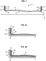
- La
figure 1 est une vue partielle en coupe transversale d'un exemple de carter de soufflante conforme à l'invention, - Les
figures 2a et 2b illustrent des étapes de fabrication du carter de soufflante de lafigure 1 , et - La
figure 3 est un organigramme représentant différentes étapes d'un exemple de réalisation du procédé de fabrication d'un carter conforme à l'invention. - Un moteur à turbine à gaz comprend généralement, d'amont en aval dans le sens de l'écoulement des gaz, une soufflante, un ou plusieurs étages de compresseurs, par exemple un compresseur basse pression et un compresseur haute pression, une chambre de combustion, un ou plusieurs étages de turbines, par exemple une turbine haute pression et une turbine basse pression, et une tuyère d'échappement des gaz.
- Les turbines sont couplées au compresseur et à la soufflante par des arbres coaxiaux respectifs.
- Le moteur est logé à l'intérieur d'un carter comprenant plusieurs parties correspondant à différents éléments du moteur. Ainsi, la soufflante est entourée par exemple par un carter de soufflante 10, qui est connecté en amont à une manche d'entrée d'air et en aval à une virole annulaire d'un carter intermédiaire.
- Le carter de soufflante 10 comprend un corps principal 12 globalement cylindrique, présentant une direction principale s'étendant selon un axe longitudinal X sensiblement parallèle à l'écoulement des gaz. Le corps principal 12 du carter peut présenter une épaisseur variable, comme indiqué dans la demande
FR 2 913 053 - Ici, le carter de soufflante 10 est réalisé en matériau composite à renfort fibreux densifié par une matrice. Le renfort est en fibres, et comprend notamment des fibres de carbone, et la matrice est en polymère, par exemple époxide, bismaélique ou polyimide.
- Le renfort peut être formé par enroulement sur un mandrin 30 d'une texture fibreuse 16 réalisée par tissage tridimensionnel avec épaisseur évolutive conformément à la description de la demande
FR 2 913 053 - Le mandrin 30 comprend une surface externe dont le profil correspond à celui de la surface interne du carter 10 à réaliser, ainsi que deux flasques 32 s'étendant radialement depuis ses extrémités libres adaptés pour former les brides 14 amont et aval du carter de soufflante 10. Par son enroulement sur le mandrin 30, la texture fibreuse 16 épouse alors le profil du mandrin 30, de sorte que ses parties d'extrémités forment les parties de préformes correspondant aux brides 14 du carter 10 en prenant appui sur les flasques 32.
- Afin de protéger des phénomènes de corrosion galvanique les pièces métalliques en contact avec le carter de soufflante 10 (manche d'entrée d'air, carter intermédiaire, virole annulaire), qui sont généralement réalisées en aluminium, on dispose en outre une couche de protection 20 contre la partie du carter 10 destinée à venir en contact avec le carter en aluminium, à savoir les brides 14 amont et aval du carter 10.
- Par exemple, la couche de protection 20 peut être disposée contre la surface des brides 14 destinée à venir en contact avec les pièces métalliques, c'est-à-dire contre la surface radiale 14a des brides 14a qui s'étend dans le prolongement de la paroi interne 13 du carter de soufflante 10. Pour la bride amont 14, il s'agit par conséquent de sa surface amont, tandis que pour la bride aval 14, il s'agit de sa surface aval.
- De la sorte, la couche de protection 20 permet d'éviter le contact entre l'aluminium et le renfort fibreux du carter de soufflante 10, et donc les phénomènes de corrosion galvanique, sans requérir aucune modification supplémentaire du carter de soufflante 10 ou des pièces métalliques. Par ailleurs, elle simplifie la maîtrise des dimensions finales du carter de soufflante 10, ainsi que les opérations de finition, la couche de protection 20 formant une surépaisseur sacrificielle pouvant être usinée facilement sans pour autant toucher les brides amont ou aval 14.
- Par exemple, la couche de protection 20 peut comprendre des fibres de verre, renforcées éventuellement par un liant. Le liant est alors choisi de manière à être compatible avec la matrice et se dissoudre dans celle-ci lors de la densification du renfort fibreux. Il peut par exemple s'agir d'une matrice polymère compatible avec les polyépoxydes. Le poids de la couche de protection 20 ainsi obtenu est donc modéré.
- La couche de protection 20 peut présenter une section transversale droite et former une partie annulaire radiale plane 22, de sorte qu'elle recouvre uniquement (mais intégralement) la surface radiale 14a de la bride 14 correspondante. Elle permet ainsi d'éviter tout contact direct avec les pièces métalliques.
- En variante, comme illustré sur la
figure 1 , la couche de protection peut présenter une section transversale en forme de L et former un anneau coudé, comprenant, outre une partie annulaire radiale 22 adaptée pour recouvrir la surface radiale 14a de la bride annulaire 14, une partie annulaire axiale 24, disposée contre la paroi interne 13 du carter de soufflante 10. - Un exemple de réalisation 100 d'un carter de soufflante 10 comprenant une couche de protection 20 contre la corrosion galvanique va à présent être décrit, dans lequel la couche de protection 20 contre la corrosion galvanique est incorporée à la texture fibreuse 16 du carter de soufflante 10 préalablement à sa densification.
- Pour cela, la couche de protection 20 est appliquée 120 sur le mandrin 30, en recouvrant les flasques 32 adaptés pour former les brides 14 du carter de soufflante 10 et l'intégralité de la surface du corps du mandrin 30.
- Selon une forme de réalisation, la couche de protection 20 est préformée aux dimensions du mandrin 30 et des flasques 32. Elle forme donc un anneau présentant un diamètre interne sensiblement égal au diamètre externe du mandrin, et dont la dimension radiale est au plus égale à celle des flasques 32. La couche de protection 20 peut par exemple être réalisée (étape 110) à partir d'une tresse, d'une bande ou d'une spirale de fibres de verre sèches, éventuellement renforcées par le liant, et est alors semi-rigide, ce qui facilite sa mise en place sur le mandrin 30 et permet de maîtriser de manière simple et rapide ses dimensions (épaisseur, diamètre, etc.) et sa qualité. De plus, la mise en oeuvre d'une couche de protection 20 semi-rigide permet de maintenir en position la texture fibreuse 16 lors de son enroulement ultérieur sur le mandrin 30, notamment en niveau du premier tour. Cette couche de protection semi-rigide 20 sera ensuite rigidifiée au moment de la densification par une matrice de la texture fibreuse 16 du carter de soufflante 10.
- En variante, la couche de protection 20 peut être réalisée en fibres de verre renforcées par une résine polymérisée. La couche de protection 20 est alors plus rigide que dans la première variante de réalisation lorsqu'elle est placée sur le mandrin 30.
- La couche de protection 20 présente alors une forme annulaire, correspondant à la forme annulaire des flasques 32 du mandrin 30, de section transversale plane ou en forme de L.
- Dans le cas d'une couche de protection 20 ayant une section transversale droite, un anneau plan est appliqué contre la surface radiale 32a de chacun des flasques 32 du mandrin 30, de sorte qu'une fois le carter de soufflante 10 réalisé, seule la surface de la bride 14 s'étendant dans le prolongement de la paroi interne 13 du carter de soufflante 10 est recouverte par la couche de protection 20.
- Dans le cas d'une couche de protection 20 ayant une section transversale en forme de L, un anneau coudé est appliqué contre la surface radiale 32a de chacun des flasques 32, en appui contre le corps du mandrin 30. Ainsi, une fois le carter de soufflante 10 réalisé, l'extrémité axiale de la paroi interne 13 du carter de soufflante 10 est également recouverte par la couche de protection 20. Cette forme de réalisation permet de mieux maintenir en position la texture fibreuse 16, d'éviter tout contact direct avec les pièces métalliques adjacentes, et d'éviter les phénomènes de corrosion galvaniques engendrés par le contact des fibres de carbone avec de l'eau retenue au niveau des brides 14 grâce à sa partie annulaire axiale 24.
- On réalise ensuite le corps principal 12 du carter en matériau composite (étape 140) par enroulement de la texture fibreuse 16 sur le mandrin 30, conformément à ce qui est décrit par exemple dans le document
FR 2 913 053 - Afin de maintenir la couche de protection 20 en position et d'éviter qu'elle ne glisse au cours de l'étape d'enroulement, on peut notamment la fixer sur le corps du mandrin 30 et/ou les flasques 32 grâce à des organes de maintien 34 (étape 130). Il peut s'agir notamment de pinces ou de clips répartis sur la circonférence du flasque 32 correspondant. Le nombre d'organes de maintien 34 dépend du diamètre du carter de soufflante 10 et des contraintes appliquées par la préforme, et peuvent être de l'ordre de 2 à 10.
- Ces organes de maintien 34 peuvent en outre être ajustables à l'épaisseur de la couche de protection 20.
- La texture fibreuse 16 est alors enroulée sur le mandrin 30 et les flasques 32, par-dessus la couche de protection 20, en évitant de recouvrir les organes de fixation 34 pour ne pas créer d'espace entre la couche de protection 20 et la texture 16. La préforme fibreuse recouvre alors la couche de protection 20, à l'exception d'un mince trottoir au niveau de la périphérie de la couche de protection 20, correspondant aux zones en contact avec les organes de maintien 34.
- Au cours d'une dernière étape (étape 150), on densifie alors la préforme fibreuse 16 ainsi que la couche de protection 20 par injection de la matrice, conformément à la description du document
FR 2 913 053 - Les dimensions finales du carter de soufflante 10 sont en outre mieux maîtrisées.
Claims (8)
- Procédé de fabrication (100) d'un carter (10) de turbomachine en matériau composite comprenant un renfort fibreux densifié par une matrice, comprenant les étapes successives suivantes :- réaliser (110) une couche de protection contre la corrosion galvanique (20) à partir d'une tresse de fibres de verre séchées, d'une bande de fibres de verre séchées ou d'une spirale de fibres de verre séchées de manière à obtenir une couche de protection contre la corrosion galvanique semi-rigide, préformée aux dimensions d'un mandrin (30) et d'un flasque radial annulaire (32), le mandrin (30) présentant un profil correspondant à celui du carter (10) à fabriquer et comprenant le flasque radial annulaire (32),- disposer (120) la couche de protection contre la corrosion galvanique (20) sur le mandrin (30), en appliquant la couche de protection (20) contre le flasque radial annulaire (32) du mandrin (30),- former (140) le renfort fibreux (16) sur le mandrin (30) en recouvrant la couche de protection contre la corrosion galvanique (20), et- densifier (150) le renfort fibreux (16) par une matrice.
- Procédé de fabrication (100) selon la revendication 1, dans lequel la couche de protection contre la corrosion galvanique (20) est renforcée par un liant.
- Procédé de fabrication (100) selon l'une des revendications 1 à 2, dans lequel la couche de protection contre la corrosion galvanique (20) est maintenue en position sur le mandrin (30) par des organes de maintien (34) fixés sur la circonférence du flasque radial annulaire (32) du mandrin (30) lors de la formation du renfort fibreux (140).
- Procédé de fabrication (100) selon la revendication 3, dans lequel les organes de maintien (34) sont ajustables à l'épaisseur de la couche de protection (20).
- Carter (10) de turbomachine en matériau composite comprenant un renfort fibreux densifié par une matrice, comprenant un corps principal (12) globalement cylindrique présentant une direction principale s'étendant selon un axe longitudinal (X), et au moins une bride (14) s'étendant radialement par rapport à l'axe longitudinal depuis une extrémité libre du corps principal (12),
caractérisé en ce qu'il comprend une couche de protection (20) contre la corrosion galvanique comprenant des fibres de verre disposée contre une surface radiale (14a) de la bride annulaire (14) et s'étendant dans le prolongement d'une paroi interne (13) du corps principal (12) et en ce qu'il est obtenu selon un procédé (100) selon l'une des revendications 1 à 4. - Carter (10) selon la revendication 5, comprenant une bride amont (14) et une bride aval (14) s'étendant radialement par rapport à l'axe longitudinal (X) depuis une extrémité libre amont et aval respectivement du corps principal (12), et dans lequel la bride amont (14) et la bride aval (14) comprennent chacune une couche de protection contre la corrosion galvanique (20) disposée contre la surface radiale (14a) desdites brides amont et aval (14) et s'étendant dans le prolongement de la paroi interne (13) du corps principal (12).
- Carter (10) selon l'une des revendications 5 ou 6, dans lequel la couche de protection contre la corrosion galvanique (20) comprend en outre un liant.
- Carter (10) selon l'une des revendications 5 à 7, dans lequel la couche de protection contre la corrosion galvanique (20) a une section transversale en L, et comprend une partie annulaire radiale (22) disposée contre la surface radiale (14a) de la bride (14), et une partie annulaire axiale (24) disposée contre la paroi interne (13) du corps principal (12).
Applications Claiming Priority (2)
| Application Number | Priority Date | Filing Date | Title |
|---|---|---|---|
| FR1256850A FR2993317B1 (fr) | 2012-07-16 | 2012-07-16 | Carter de turbomachine dans un materiau composite et procede de fabrication associe |
| PCT/FR2013/051626 WO2014013161A1 (fr) | 2012-07-16 | 2013-07-08 | Procédé de fabrication d'un carter de turbomachine dans un matériau composite et carter associé |
Publications (2)
| Publication Number | Publication Date |
|---|---|
| EP2872746A1 EP2872746A1 (fr) | 2015-05-20 |
| EP2872746B1 true EP2872746B1 (fr) | 2018-12-26 |
Family
ID=47553188
Family Applications (1)
| Application Number | Title | Priority Date | Filing Date |
|---|---|---|---|
| EP13744717.3A Active EP2872746B1 (fr) | 2012-07-16 | 2013-07-08 | Procédé de fabrication d'un carter de turbomachine dans un matériau composite et carter associé |
Country Status (9)
| Country | Link |
|---|---|
| US (1) | US9909447B2 (fr) |
| EP (1) | EP2872746B1 (fr) |
| JP (1) | JP2015524757A (fr) |
| CN (1) | CN104471195B (fr) |
| BR (1) | BR112015001033B1 (fr) |
| CA (1) | CA2879052C (fr) |
| FR (1) | FR2993317B1 (fr) |
| RU (1) | RU2637282C2 (fr) |
| WO (1) | WO2014013161A1 (fr) |
Families Citing this family (8)
| Publication number | Priority date | Publication date | Assignee | Title |
|---|---|---|---|---|
| US10392950B2 (en) * | 2015-05-07 | 2019-08-27 | General Electric Company | Turbine band anti-chording flanges |
| EP3311031B1 (fr) * | 2015-06-18 | 2026-02-25 | Nuovo Pignone Tecnologie - S.r.l. | Carter pour turbomachine |
| CN109313197A (zh) | 2016-04-15 | 2019-02-05 | 费利克斯疗法公司 | 使用静止细胞靶向和有丝分裂抑制剂的用于治疗肿瘤的组合 |
| CN107399091B (zh) * | 2017-07-11 | 2019-09-06 | 北京汽车集团有限公司 | 异形复合材料轴、其制备方法以及与金属法兰的连接方法 |
| FR3074088B1 (fr) * | 2017-11-30 | 2021-02-12 | Safran Aircraft Engines | Carter en materiau composite renforce et son procede de fabrication |
| FR3100561B1 (fr) * | 2019-09-10 | 2023-01-20 | Safran Aircraft Engines | Fixation d’une virole acoustique a une enveloppe de carter pour une turbomachine d’aeronef |
| FR3105076B1 (fr) * | 2019-12-23 | 2023-04-14 | Safran Aircraft Engines | Procede de fabrication d’un carter pour une turbomachine d’aeronef |
| CN117445243A (zh) * | 2023-12-21 | 2024-01-26 | 浙江航引新材料科技有限公司 | 一种法兰纤维预制体及其制备方法 |
Family Cites Families (13)
| Publication number | Priority date | Publication date | Assignee | Title |
|---|---|---|---|---|
| KR200181300Y1 (ko) * | 1999-12-13 | 2000-05-15 | 포항종합제철주식회사 | 플랜지 이음에 있어서 갈바닉 부식 방지 장치 |
| FR2869074B1 (fr) * | 2004-04-14 | 2006-07-21 | Snecma Moteurs Sa | Systeme de protection d'arbre principal de moteur a palier fusible |
| US7431978B2 (en) * | 2004-12-22 | 2008-10-07 | General Electric Company | Reinforced matrix composite containment duct |
| US7246990B2 (en) * | 2004-12-23 | 2007-07-24 | General Electric Company | Composite fan containment case for turbine engines |
| US7429165B2 (en) * | 2006-06-14 | 2008-09-30 | General Electric Company | Hybrid blade for a steam turbine |
| DE102006041321A1 (de) * | 2006-09-01 | 2008-03-06 | Rolls-Royce Deutschland Ltd & Co Kg | Gehäuseabschnitt, insbesondere Fangehäuse, für ein Gasturbinentriebwerk |
| US7713021B2 (en) * | 2006-12-13 | 2010-05-11 | General Electric Company | Fan containment casings and methods of manufacture |
| US20080157418A1 (en) * | 2006-12-27 | 2008-07-03 | Lee Alan Blanton | Methods for fabricating composite structures with flanges having tethered corners |
| FR2913053B1 (fr) * | 2007-02-23 | 2009-05-22 | Snecma Sa | Procede de fabrication d'un carter de turbine a gaz en materiau composite et carter ainsi obtenu |
| US9032706B2 (en) * | 2008-09-26 | 2015-05-19 | Pratt & Whitney Canada Corp. | Composite fan case with integral containment zone |
| US9140135B2 (en) * | 2010-09-28 | 2015-09-22 | United Technologies Corporation | Metallic radius block for composite flange |
| US8672609B2 (en) * | 2009-08-31 | 2014-03-18 | United Technologies Corporation | Composite fan containment case assembly |
| FR2966508B1 (fr) * | 2010-10-22 | 2015-04-03 | Snecma | Carter de soufflante de moteur aeronautique en materiau composite et procede pour sa fabrication |
-
2012
- 2012-07-16 FR FR1256850A patent/FR2993317B1/fr active Active
-
2013
- 2013-07-08 JP JP2015522142A patent/JP2015524757A/ja active Pending
- 2013-07-08 RU RU2015104986A patent/RU2637282C2/ru active
- 2013-07-08 BR BR112015001033-4A patent/BR112015001033B1/pt active IP Right Grant
- 2013-07-08 US US14/415,183 patent/US9909447B2/en active Active
- 2013-07-08 CN CN201380037741.0A patent/CN104471195B/zh active Active
- 2013-07-08 CA CA2879052A patent/CA2879052C/fr active Active
- 2013-07-08 EP EP13744717.3A patent/EP2872746B1/fr active Active
- 2013-07-08 WO PCT/FR2013/051626 patent/WO2014013161A1/fr not_active Ceased
Non-Patent Citations (1)
| Title |
|---|
| None * |
Also Published As
| Publication number | Publication date |
|---|---|
| BR112015001033B1 (pt) | 2021-11-30 |
| CA2879052A1 (fr) | 2014-01-23 |
| BR112015001033A2 (pt) | 2017-06-27 |
| CA2879052C (fr) | 2020-04-14 |
| RU2637282C2 (ru) | 2017-12-01 |
| FR2993317A1 (fr) | 2014-01-17 |
| US20150192032A1 (en) | 2015-07-09 |
| EP2872746A1 (fr) | 2015-05-20 |
| CN104471195A (zh) | 2015-03-25 |
| JP2015524757A (ja) | 2015-08-27 |
| CN104471195B (zh) | 2016-08-17 |
| FR2993317B1 (fr) | 2014-08-15 |
| RU2015104986A (ru) | 2016-09-10 |
| WO2014013161A1 (fr) | 2014-01-23 |
| US9909447B2 (en) | 2018-03-06 |
Similar Documents
| Publication | Publication Date | Title |
|---|---|---|
| EP2872746B1 (fr) | Procédé de fabrication d'un carter de turbomachine dans un matériau composite et carter associé | |
| EP3847006B1 (fr) | Carter en materiau composite avec raidisseur integre | |
| CA2957608C (fr) | Carter en materiau composite a matrice organique auto-raidi | |
| EP1961923B1 (fr) | Procédé de fabrication d'un carter de turbine à gaz en matériau composite et carter ainsi obtenu. | |
| EP3092375B1 (fr) | Protection contre le feu d'un carter de soufflante en matériau composite | |
| WO2013007937A2 (fr) | Procede de fabrication d'un carter de soufflante de turbomachine muni de revetement acoustique. | |
| FR2966508A1 (fr) | Carter de soufflante de moteur aeronautique en materiau composite et procede pour sa fabrication | |
| EP3453847B1 (fr) | Carter en matériau composite à géométrie raidissante | |
| FR2986580A1 (fr) | Piece de revolution de rotor de turbomachine aeronautique | |
| EP3930991A1 (fr) | Reparation ou reprise de fabrication d' une piece en materiau composite | |
| FR2956875A1 (fr) | Aube allegee pour turbomachine, carter comportant une pluralite d'une telle aube et turbomachine comportant au moins un tel carter | |
| FR3037854A1 (fr) | Procede de fabrication d'un carter de soufflante en materiau composite a panneau abradable integre pour moteur a turbine a gaz et carter ainsi obtenu | |
| EP4320339A1 (fr) | Virole exterieure de carter intermediaire en materiau composite, pour turbomachine d'aeronef | |
| EP4028645A1 (fr) | Fixation d'une virole acoustique a une enveloppé de carter pour une turbomachine d'aéronef | |
| EP2714517B1 (fr) | Ensemble pour une nacelle d'aéronef | |
| EP3057773B1 (fr) | Procédé de liaison d'une jupette a une enveloppe d'un corps de propulseur | |
| FR3059044A1 (fr) | Carter de soufflante de turbomachine aeronautique | |
| WO2020157438A1 (fr) | Carter de soufflante pour une turbomachine d'aeronef | |
| FR3146160A1 (fr) | Carter annulaire de turbomachine et son procédé de fabrication. | |
| FR3087827A1 (fr) | Carter de soufflante en materiau composite comprenant des brides metalliques | |
| FR2993490A1 (fr) | Moule pour la fabrication d'un carter de turbine en materiau composite et procede de fabrication d'un tel carter au moyen du moule | |
| FR3151879A1 (fr) | Virole annulaire pour un carter de turbomachine et son procede de fabrication | |
| FR3141637A1 (fr) | Texture fibreuse pour carter en matériau composite auto-raidi |
Legal Events
| Date | Code | Title | Description |
|---|---|---|---|
| PUAI | Public reference made under article 153(3) epc to a published international application that has entered the european phase |
Free format text: ORIGINAL CODE: 0009012 |
|
| 17P | Request for examination filed |
Effective date: 20150216 |
|
| AK | Designated contracting states |
Kind code of ref document: A1 Designated state(s): AL AT BE BG CH CY CZ DE DK EE ES FI FR GB GR HR HU IE IS IT LI LT LU LV MC MK MT NL NO PL PT RO RS SE SI SK SM TR |
|
| AX | Request for extension of the european patent |
Extension state: BA ME |
|
| DAX | Request for extension of the european patent (deleted) | ||
| STAA | Information on the status of an ep patent application or granted ep patent |
Free format text: STATUS: EXAMINATION IS IN PROGRESS |
|
| 17Q | First examination report despatched |
Effective date: 20180103 |
|
| REG | Reference to a national code |
Ref country code: DE Ref legal event code: R079 Ref document number: 602013048799 Country of ref document: DE Free format text: PREVIOUS MAIN CLASS: F01D0021040000 Ipc: B29C0070300000 |
|
| RIC1 | Information provided on ipc code assigned before grant |
Ipc: F01D 25/24 20060101ALI20180525BHEP Ipc: B29C 70/54 20060101ALI20180525BHEP Ipc: F01D 25/00 20060101ALI20180525BHEP Ipc: B29K 105/08 20060101ALI20180525BHEP Ipc: F01D 21/04 20060101ALI20180525BHEP Ipc: B29K 309/08 20060101ALI20180525BHEP Ipc: B29C 70/30 20060101AFI20180525BHEP |
|
| GRAP | Despatch of communication of intention to grant a patent |
Free format text: ORIGINAL CODE: EPIDOSNIGR1 |
|
| STAA | Information on the status of an ep patent application or granted ep patent |
Free format text: STATUS: GRANT OF PATENT IS INTENDED |
|
| RAP1 | Party data changed (applicant data changed or rights of an application transferred) |
Owner name: SAFRAN AIRCRAFT ENGINES |
|
| INTG | Intention to grant announced |
Effective date: 20180711 |
|
| GRAS | Grant fee paid |
Free format text: ORIGINAL CODE: EPIDOSNIGR3 |
|
| GRAA | (expected) grant |
Free format text: ORIGINAL CODE: 0009210 |
|
| STAA | Information on the status of an ep patent application or granted ep patent |
Free format text: STATUS: THE PATENT HAS BEEN GRANTED |
|
| AK | Designated contracting states |
Kind code of ref document: B1 Designated state(s): AL AT BE BG CH CY CZ DE DK EE ES FI FR GB GR HR HU IE IS IT LI LT LU LV MC MK MT NL NO PL PT RO RS SE SI SK SM TR |
|
| REG | Reference to a national code |
Ref country code: GB Ref legal event code: FG4D Free format text: NOT ENGLISH |
|
| REG | Reference to a national code |
Ref country code: CH Ref legal event code: EP |
|
| REG | Reference to a national code |
Ref country code: AT Ref legal event code: REF Ref document number: 1080811 Country of ref document: AT Kind code of ref document: T Effective date: 20190115 |
|
| REG | Reference to a national code |
Ref country code: IE Ref legal event code: FG4D Free format text: LANGUAGE OF EP DOCUMENT: FRENCH |
|
| REG | Reference to a national code |
Ref country code: DE Ref legal event code: R096 Ref document number: 602013048799 Country of ref document: DE |
|
| PG25 | Lapsed in a contracting state [announced via postgrant information from national office to epo] |
Ref country code: BG Free format text: LAPSE BECAUSE OF FAILURE TO SUBMIT A TRANSLATION OF THE DESCRIPTION OR TO PAY THE FEE WITHIN THE PRESCRIBED TIME-LIMIT Effective date: 20190326 Ref country code: HR Free format text: LAPSE BECAUSE OF FAILURE TO SUBMIT A TRANSLATION OF THE DESCRIPTION OR TO PAY THE FEE WITHIN THE PRESCRIBED TIME-LIMIT Effective date: 20181226 Ref country code: LT Free format text: LAPSE BECAUSE OF FAILURE TO SUBMIT A TRANSLATION OF THE DESCRIPTION OR TO PAY THE FEE WITHIN THE PRESCRIBED TIME-LIMIT Effective date: 20181226 Ref country code: NO Free format text: LAPSE BECAUSE OF FAILURE TO SUBMIT A TRANSLATION OF THE DESCRIPTION OR TO PAY THE FEE WITHIN THE PRESCRIBED TIME-LIMIT Effective date: 20190326 Ref country code: LV Free format text: LAPSE BECAUSE OF FAILURE TO SUBMIT A TRANSLATION OF THE DESCRIPTION OR TO PAY THE FEE WITHIN THE PRESCRIBED TIME-LIMIT Effective date: 20181226 Ref country code: FI Free format text: LAPSE BECAUSE OF FAILURE TO SUBMIT A TRANSLATION OF THE DESCRIPTION OR TO PAY THE FEE WITHIN THE PRESCRIBED TIME-LIMIT Effective date: 20181226 |
|
| REG | Reference to a national code |
Ref country code: NL Ref legal event code: MP Effective date: 20181226 |
|
| REG | Reference to a national code |
Ref country code: LT Ref legal event code: MG4D |
|
| PG25 | Lapsed in a contracting state [announced via postgrant information from national office to epo] |
Ref country code: AL Free format text: LAPSE BECAUSE OF FAILURE TO SUBMIT A TRANSLATION OF THE DESCRIPTION OR TO PAY THE FEE WITHIN THE PRESCRIBED TIME-LIMIT Effective date: 20181226 Ref country code: SE Free format text: LAPSE BECAUSE OF FAILURE TO SUBMIT A TRANSLATION OF THE DESCRIPTION OR TO PAY THE FEE WITHIN THE PRESCRIBED TIME-LIMIT Effective date: 20181226 Ref country code: RS Free format text: LAPSE BECAUSE OF FAILURE TO SUBMIT A TRANSLATION OF THE DESCRIPTION OR TO PAY THE FEE WITHIN THE PRESCRIBED TIME-LIMIT Effective date: 20181226 Ref country code: GR Free format text: LAPSE BECAUSE OF FAILURE TO SUBMIT A TRANSLATION OF THE DESCRIPTION OR TO PAY THE FEE WITHIN THE PRESCRIBED TIME-LIMIT Effective date: 20190327 |
|
| REG | Reference to a national code |
Ref country code: AT Ref legal event code: MK05 Ref document number: 1080811 Country of ref document: AT Kind code of ref document: T Effective date: 20181226 |
|
| PG25 | Lapsed in a contracting state [announced via postgrant information from national office to epo] |
Ref country code: NL Free format text: LAPSE BECAUSE OF FAILURE TO SUBMIT A TRANSLATION OF THE DESCRIPTION OR TO PAY THE FEE WITHIN THE PRESCRIBED TIME-LIMIT Effective date: 20181226 |
|
| PG25 | Lapsed in a contracting state [announced via postgrant information from national office to epo] |
Ref country code: PL Free format text: LAPSE BECAUSE OF FAILURE TO SUBMIT A TRANSLATION OF THE DESCRIPTION OR TO PAY THE FEE WITHIN THE PRESCRIBED TIME-LIMIT Effective date: 20181226 Ref country code: IT Free format text: LAPSE BECAUSE OF FAILURE TO SUBMIT A TRANSLATION OF THE DESCRIPTION OR TO PAY THE FEE WITHIN THE PRESCRIBED TIME-LIMIT Effective date: 20181226 Ref country code: ES Free format text: LAPSE BECAUSE OF FAILURE TO SUBMIT A TRANSLATION OF THE DESCRIPTION OR TO PAY THE FEE WITHIN THE PRESCRIBED TIME-LIMIT Effective date: 20181226 Ref country code: CZ Free format text: LAPSE BECAUSE OF FAILURE TO SUBMIT A TRANSLATION OF THE DESCRIPTION OR TO PAY THE FEE WITHIN THE PRESCRIBED TIME-LIMIT Effective date: 20181226 Ref country code: PT Free format text: LAPSE BECAUSE OF FAILURE TO SUBMIT A TRANSLATION OF THE DESCRIPTION OR TO PAY THE FEE WITHIN THE PRESCRIBED TIME-LIMIT Effective date: 20190426 |
|
| PG25 | Lapsed in a contracting state [announced via postgrant information from national office to epo] |
Ref country code: RO Free format text: LAPSE BECAUSE OF FAILURE TO SUBMIT A TRANSLATION OF THE DESCRIPTION OR TO PAY THE FEE WITHIN THE PRESCRIBED TIME-LIMIT Effective date: 20181226 Ref country code: IS Free format text: LAPSE BECAUSE OF FAILURE TO SUBMIT A TRANSLATION OF THE DESCRIPTION OR TO PAY THE FEE WITHIN THE PRESCRIBED TIME-LIMIT Effective date: 20190426 Ref country code: SK Free format text: LAPSE BECAUSE OF FAILURE TO SUBMIT A TRANSLATION OF THE DESCRIPTION OR TO PAY THE FEE WITHIN THE PRESCRIBED TIME-LIMIT Effective date: 20181226 Ref country code: SM Free format text: LAPSE BECAUSE OF FAILURE TO SUBMIT A TRANSLATION OF THE DESCRIPTION OR TO PAY THE FEE WITHIN THE PRESCRIBED TIME-LIMIT Effective date: 20181226 Ref country code: EE Free format text: LAPSE BECAUSE OF FAILURE TO SUBMIT A TRANSLATION OF THE DESCRIPTION OR TO PAY THE FEE WITHIN THE PRESCRIBED TIME-LIMIT Effective date: 20181226 |
|
| REG | Reference to a national code |
Ref country code: DE Ref legal event code: R097 Ref document number: 602013048799 Country of ref document: DE |
|
| PG25 | Lapsed in a contracting state [announced via postgrant information from national office to epo] |
Ref country code: DK Free format text: LAPSE BECAUSE OF FAILURE TO SUBMIT A TRANSLATION OF THE DESCRIPTION OR TO PAY THE FEE WITHIN THE PRESCRIBED TIME-LIMIT Effective date: 20181226 Ref country code: AT Free format text: LAPSE BECAUSE OF FAILURE TO SUBMIT A TRANSLATION OF THE DESCRIPTION OR TO PAY THE FEE WITHIN THE PRESCRIBED TIME-LIMIT Effective date: 20181226 |
|
| PLBE | No opposition filed within time limit |
Free format text: ORIGINAL CODE: 0009261 |
|
| STAA | Information on the status of an ep patent application or granted ep patent |
Free format text: STATUS: NO OPPOSITION FILED WITHIN TIME LIMIT |
|
| 26N | No opposition filed |
Effective date: 20190927 |
|
| PG25 | Lapsed in a contracting state [announced via postgrant information from national office to epo] |
Ref country code: SI Free format text: LAPSE BECAUSE OF FAILURE TO SUBMIT A TRANSLATION OF THE DESCRIPTION OR TO PAY THE FEE WITHIN THE PRESCRIBED TIME-LIMIT Effective date: 20181226 Ref country code: MC Free format text: LAPSE BECAUSE OF FAILURE TO SUBMIT A TRANSLATION OF THE DESCRIPTION OR TO PAY THE FEE WITHIN THE PRESCRIBED TIME-LIMIT Effective date: 20181226 |
|
| REG | Reference to a national code |
Ref country code: CH Ref legal event code: PL |
|
| PG25 | Lapsed in a contracting state [announced via postgrant information from national office to epo] |
Ref country code: TR Free format text: LAPSE BECAUSE OF FAILURE TO SUBMIT A TRANSLATION OF THE DESCRIPTION OR TO PAY THE FEE WITHIN THE PRESCRIBED TIME-LIMIT Effective date: 20181226 |
|
| REG | Reference to a national code |
Ref country code: BE Ref legal event code: MM Effective date: 20190731 |
|
| PG25 | Lapsed in a contracting state [announced via postgrant information from national office to epo] |
Ref country code: LI Free format text: LAPSE BECAUSE OF NON-PAYMENT OF DUE FEES Effective date: 20190731 Ref country code: BE Free format text: LAPSE BECAUSE OF NON-PAYMENT OF DUE FEES Effective date: 20190731 Ref country code: LU Free format text: LAPSE BECAUSE OF NON-PAYMENT OF DUE FEES Effective date: 20190708 Ref country code: CH Free format text: LAPSE BECAUSE OF NON-PAYMENT OF DUE FEES Effective date: 20190731 |
|
| PG25 | Lapsed in a contracting state [announced via postgrant information from national office to epo] |
Ref country code: IE Free format text: LAPSE BECAUSE OF NON-PAYMENT OF DUE FEES Effective date: 20190708 |
|
| PG25 | Lapsed in a contracting state [announced via postgrant information from national office to epo] |
Ref country code: CY Free format text: LAPSE BECAUSE OF FAILURE TO SUBMIT A TRANSLATION OF THE DESCRIPTION OR TO PAY THE FEE WITHIN THE PRESCRIBED TIME-LIMIT Effective date: 20181226 |
|
| PG25 | Lapsed in a contracting state [announced via postgrant information from national office to epo] |
Ref country code: HU Free format text: LAPSE BECAUSE OF FAILURE TO SUBMIT A TRANSLATION OF THE DESCRIPTION OR TO PAY THE FEE WITHIN THE PRESCRIBED TIME-LIMIT; INVALID AB INITIO Effective date: 20130708 Ref country code: MT Free format text: LAPSE BECAUSE OF FAILURE TO SUBMIT A TRANSLATION OF THE DESCRIPTION OR TO PAY THE FEE WITHIN THE PRESCRIBED TIME-LIMIT Effective date: 20181226 |
|
| PG25 | Lapsed in a contracting state [announced via postgrant information from national office to epo] |
Ref country code: MK Free format text: LAPSE BECAUSE OF FAILURE TO SUBMIT A TRANSLATION OF THE DESCRIPTION OR TO PAY THE FEE WITHIN THE PRESCRIBED TIME-LIMIT Effective date: 20181226 |
|
| PGFP | Annual fee paid to national office [announced via postgrant information from national office to epo] |
Ref country code: DE Payment date: 20250722 Year of fee payment: 13 |
|
| PGFP | Annual fee paid to national office [announced via postgrant information from national office to epo] |
Ref country code: GB Payment date: 20250724 Year of fee payment: 13 |
|
| PGFP | Annual fee paid to national office [announced via postgrant information from national office to epo] |
Ref country code: FR Payment date: 20250722 Year of fee payment: 13 |