EP2872832B1 - Feuerfeste garvorrichtung - Google Patents
Feuerfeste garvorrichtung Download PDFInfo
- Publication number
- EP2872832B1 EP2872832B1 EP13819686.0A EP13819686A EP2872832B1 EP 2872832 B1 EP2872832 B1 EP 2872832B1 EP 13819686 A EP13819686 A EP 13819686A EP 2872832 B1 EP2872832 B1 EP 2872832B1
- Authority
- EP
- European Patent Office
- Prior art keywords
- refractory
- thermal energy
- cooking
- oven
- piece
- Prior art date
- Legal status (The legal status is an assumption and is not a legal conclusion. Google has not performed a legal analysis and makes no representation as to the accuracy of the status listed.)
- Active
Links
Images




Classifications
-
- F—MECHANICAL ENGINEERING; LIGHTING; HEATING; WEAPONS; BLASTING
- F24—HEATING; RANGES; VENTILATING
- F24C—DOMESTIC STOVES OR RANGES ; DETAILS OF DOMESTIC STOVES OR RANGES, OF GENERAL APPLICATION
- F24C15/00—Details
-
- A—HUMAN NECESSITIES
- A47—FURNITURE; DOMESTIC ARTICLES OR APPLIANCES; COFFEE MILLS; SPICE MILLS; SUCTION CLEANERS IN GENERAL
- A47J—KITCHEN EQUIPMENT; COFFEE MILLS; SPICE MILLS; APPARATUS FOR MAKING BEVERAGES
- A47J37/00—Baking; Roasting; Grilling; Frying
- A47J37/06—Roasters; Grills; Sandwich grills
- A47J37/0623—Small-size cooking ovens, i.e. defining an at least partially closed cooking cavity
- A47J37/0658—Small-size cooking ovens, i.e. defining an at least partially closed cooking cavity specially adapted for cooking pizza
-
- A—HUMAN NECESSITIES
- A21—BAKING; EDIBLE DOUGHS
- A21B—BAKERS' OVENS; MACHINES OR EQUIPMENT FOR BAKING
- A21B1/00—Bakers' ovens
-
- A—HUMAN NECESSITIES
- A21—BAKING; EDIBLE DOUGHS
- A21B—BAKERS' OVENS; MACHINES OR EQUIPMENT FOR BAKING
- A21B1/00—Bakers' ovens
- A21B1/52—Portable ovens; Collapsible ovens
-
- A—HUMAN NECESSITIES
- A47—FURNITURE; DOMESTIC ARTICLES OR APPLIANCES; COFFEE MILLS; SPICE MILLS; SUCTION CLEANERS IN GENERAL
- A47J—KITCHEN EQUIPMENT; COFFEE MILLS; SPICE MILLS; APPARATUS FOR MAKING BEVERAGES
- A47J37/00—Baking; Roasting; Grilling; Frying
- A47J37/06—Roasters; Grills; Sandwich grills
- A47J37/0623—Small-size cooking ovens, i.e. defining an at least partially closed cooking cavity
-
- A—HUMAN NECESSITIES
- A47—FURNITURE; DOMESTIC ARTICLES OR APPLIANCES; COFFEE MILLS; SPICE MILLS; SUCTION CLEANERS IN GENERAL
- A47J—KITCHEN EQUIPMENT; COFFEE MILLS; SPICE MILLS; APPARATUS FOR MAKING BEVERAGES
- A47J37/00—Baking; Roasting; Grilling; Frying
- A47J37/06—Roasters; Grills; Sandwich grills
- A47J37/0623—Small-size cooking ovens, i.e. defining an at least partially closed cooking cavity
- A47J37/0647—Small-size cooking ovens, i.e. defining an at least partially closed cooking cavity with gas burners
-
- A—HUMAN NECESSITIES
- A47—FURNITURE; DOMESTIC ARTICLES OR APPLIANCES; COFFEE MILLS; SPICE MILLS; SUCTION CLEANERS IN GENERAL
- A47J—KITCHEN EQUIPMENT; COFFEE MILLS; SPICE MILLS; APPARATUS FOR MAKING BEVERAGES
- A47J37/00—Baking; Roasting; Grilling; Frying
- A47J37/06—Roasters; Grills; Sandwich grills
- A47J37/07—Roasting devices for outdoor use; Barbecues
- A47J37/0704—Roasting devices for outdoor use; Barbecues with horizontal fire box
-
- A—HUMAN NECESSITIES
- A47—FURNITURE; DOMESTIC ARTICLES OR APPLIANCES; COFFEE MILLS; SPICE MILLS; SUCTION CLEANERS IN GENERAL
- A47J—KITCHEN EQUIPMENT; COFFEE MILLS; SPICE MILLS; APPARATUS FOR MAKING BEVERAGES
- A47J37/00—Baking; Roasting; Grilling; Frying
- A47J37/06—Roasters; Grills; Sandwich grills
- A47J37/07—Roasting devices for outdoor use; Barbecues
- A47J37/0759—Roasting devices for outdoor use; Barbecues constructed from refractory blocks
-
- A—HUMAN NECESSITIES
- A47—FURNITURE; DOMESTIC ARTICLES OR APPLIANCES; COFFEE MILLS; SPICE MILLS; SUCTION CLEANERS IN GENERAL
- A47J—KITCHEN EQUIPMENT; COFFEE MILLS; SPICE MILLS; APPARATUS FOR MAKING BEVERAGES
- A47J37/00—Baking; Roasting; Grilling; Frying
- A47J37/06—Roasters; Grills; Sandwich grills
- A47J37/07—Roasting devices for outdoor use; Barbecues
- A47J37/0786—Accessories
-
- F—MECHANICAL ENGINEERING; LIGHTING; HEATING; WEAPONS; BLASTING
- F24—HEATING; RANGES; VENTILATING
- F24B—DOMESTIC STOVES OR RANGES FOR SOLID FUELS; IMPLEMENTS FOR USE IN CONNECTION WITH STOVES OR RANGES
- F24B1/00—Stoves or ranges
- F24B1/003—Stoves or ranges on which a removable cooking element is arranged
-
- F—MECHANICAL ENGINEERING; LIGHTING; HEATING; WEAPONS; BLASTING
- F24—HEATING; RANGES; VENTILATING
- F24C—DOMESTIC STOVES OR RANGES ; DETAILS OF DOMESTIC STOVES OR RANGES, OF GENERAL APPLICATION
- F24C15/00—Details
- F24C15/08—Foundations or supports plates; Legs or pillars; Casings; Wheels
-
- F—MECHANICAL ENGINEERING; LIGHTING; HEATING; WEAPONS; BLASTING
- F24—HEATING; RANGES; VENTILATING
- F24C—DOMESTIC STOVES OR RANGES ; DETAILS OF DOMESTIC STOVES OR RANGES, OF GENERAL APPLICATION
- F24C3/00—Stoves or ranges for gaseous fuels
-
- Y—GENERAL TAGGING OF NEW TECHNOLOGICAL DEVELOPMENTS; GENERAL TAGGING OF CROSS-SECTIONAL TECHNOLOGIES SPANNING OVER SEVERAL SECTIONS OF THE IPC; TECHNICAL SUBJECTS COVERED BY FORMER USPC CROSS-REFERENCE ART COLLECTIONS [XRACs] AND DIGESTS
- Y02—TECHNOLOGIES OR APPLICATIONS FOR MITIGATION OR ADAPTATION AGAINST CLIMATE CHANGE
- Y02A—TECHNOLOGIES FOR ADAPTATION TO CLIMATE CHANGE
- Y02A40/00—Adaptation technologies in agriculture, forestry, livestock or agroalimentary production
- Y02A40/90—Adaptation technologies in agriculture, forestry, livestock or agroalimentary production in food processing or handling, e.g. food conservation
- Y02A40/924—Adaptation technologies in agriculture, forestry, livestock or agroalimentary production in food processing or handling, e.g. food conservation using renewable energies
- Y02A40/928—Cooking stoves using biomass
Definitions
- Properly cooking certain foods may include the introduction of the foods into a high-heat environment for a short period.
- specific characteristics of the food may be achieved.
- properly cooking a New York style pizza and/or a Neapolitan style pizza may include introducing an uncooked pizza into an oven with a temperature between about 315,56 degrees Celsius (600 degrees Fahrenheit) and about 593,33 degrees Celsius (1100 degrees Fahrenheit) for between three and six minutes.
- the high-heat environment may scorch the crust of the pizza while simultaneously heating toppings and melting cheese.
- high-heat environments are difficult, expensive, and inefficient in residential and small-scale situations.
- high-heat environments are produced in large ovens that may cost thousands of dollars and may occupy large spaces.
- the large ovens may inefficiently consume fuel during the heating and lose much of the heat following use.
- cooking using the large oven may involve learning "hot spots” and "cool spots” which may be geometrically or environmentally determined.
- FR2468839 (A1 ) describes a wood burning stove with a cooking chamber that has a rectangular base and a half-cylindrical top.
- the chamber is formed by a half cylindrical refractory lining with end plates and a refractory base.
- JP2006102488 (A ) describes a portable cooking utensil comprising a cover section and a pan section which are formed of a material having a thermal storage property and heat resistance.
- US6101930 (A ) describes a baking device for use in a domestic oven.
- the baking device comprises a refractory insulating material and includes a base and a pair of walls.
- US2010/147281 (A1 ) describes a method of baking bread in a high temperature bake oven comprising a lower portion, a first pizza stone and a second pizza stone located above the first pizza stone.
- US 2006/191528 (A1 ) describes a cooking oven configured for use with a separate heat source such as a gas grill having one or more burners.
- the cooking device includes a refractory oven and a housing.
- the refractory oven defines a cooking chamber that is configured to receive thermal energy from an external heat source.
- the cooking device may create a high-heat environment that may be suitable to cook foodstuffs such as New York style pizza Neapolitan style pizza, steaks, casseroles, cookies, cakes, etc.
- high-heat may generally refer to an environment having a temperature between about 315,56 degrees Celsius (600 degrees Fahrenheit) and about 593,33 degrees Celsius (1100 degrees Fahrenheit).
- the refractory oven also defines an opening and a vent.
- the opening is configured to allow foodstuffs to be introduced into the cooking chamber.
- the refractory oven is may configured to absorb thermal energy received from the external heat source and transfer the thermal energy to foodstuffs in contact with a cooking surface of the refractory oven via thermal conduction.
- the refractory oven is may configured to absorb the thermal energy and transfer the thermal energy to the foodstuffs via thermal radiation.
- the vent and the opening are configured to allow the thermal energy from the external heat source to enter the cooking chamber through the vent. The thermal energy is then transferred to the foodstuffs via thermal convection.
- the housing at least partially surrounds the refractory oven.
- the housing and the refractory oven define a heated volume between an external surface of the refractory oven and an internal surface of the housing.
- the heated volume is configured to receive thermal energy from the external heat source and to reduce transfer of thermal energy from the cooking chamber through the refractory oven.
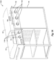
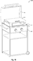
- Figs. 1A and 1B illustrate example cooking systems 100A and 100B in accordance with at least one embodiment described herein.
- the cooking systems 100A and 100B may include an external heat source 102 that may be configured to produce thermal energy that may be received by a cooking device 104.
- the cooking device 104 may be configured to be positioned relative to the external heat source 102 such that the thermal energy produced by the external heat source 102 may be received by the cooking device 104.
- the cooking device 104 may be configured to then transfer the thermal energy to foodstuffs positioned inside the cooking device 104.
- the cooking device 104 may use the thermal energy produced by the external heat source 102 to create a high-heat environment.
- the cooking device 104 may be positioned on top of or generally above the external heat source 102.
- the thermal energy produced by the external heat source 102 may accordingly heat a bottom portion of the cooking device 104.
- the cooking device 104 may be positioned to the side of, in front of, below, or within the external heat source 102.
- the cooking device 104 may receive the thermal energy along a side portion, a rear portion, the bottom portion, a top portion or any combination thereof.
- the external heat source 102 may include a lid 112.
- the lid 112 is depicted in an open position.
- the cooking device 104 may be positioned on a grilling surface 114 of the external heat source 102 and the lid 112 may be moved to a closed position. In this circumstance, the cooking device 104 may be substantially within the external heat source 102.
- the external heat source 102 may include a rotisserie cooking element, or the like, that is positioned along a rear portion of the cooking device 104. In the alternative example, the cooking device 104 may receive thermal energy from a bottom portion and/or along a rear portion.
- a user may disassemble the cooking device 104.
- the user may introduce some alternative external heat sources to the cooking device 104 or may enable direct heating through a disassembled portion of the cooking device 104.
- a user may remove a rear portion of the cooking device 104 to allow the thermal energy from the rotisserie cooking element to more directly heat the cooking device 104.
- the cooking device 104 may be removable from the external heat source 102.
- the removability of the cooking device 104 may enable the cooking device 104 to be positioned relative to one or more different external heat sources and may enable use of the external heat source 102 without the cooking device 104.
- the external heat source 102 may include a propane grill.
- the cooking device 104 may substantially cover the grilling surface 114.
- a user may remove the cooking device 104 from the external heat source 102.
- the cooking device 104 may be removable or may be attached to the external heat source 102.
- the cooking system 100A includes the cooking device 104, which may be positioned next to an independent grill 106.
- the cooking device 104 and the independent grill 106 may share a support structure 108.
- the cooking device 104 may be secured to the support structure 108 during a substantial portion of the useful life of the cooking system 100A.
- the cooking device 104 may be removed from the support structure 108 between uses to enable another application of the external heat source 102.
- the cooking system 100A includes the independent grill 106, which may include, but is not limited to, a propane grill, a natural gas grill, a charcoal grill, a wood grill, an electrical grill, etc.
- the configuration of the cooking system 100A is not meant to be limiting.
- the cooking system 100A may only include the cooking device 104, which may be attached to the support structure 108.
- the cooking device 104 may be paired with another appliance or device.
- the cooking device 104 and the external heat source 102 may share a fuel and/or a fuel source (not shown).
- the independent grill 106 may use propane gas as a fuel.
- One or more knobs 110A may control a supply of the fuel to the independent grill 106, while one or more other knobs 110B may control a supply of the fuel to the cooking device 104.
- the independent grill 106 and the cooking device 104 may be fueled by different fuel sources.
- the grill 106 may be charcoal or wood grill while the cooking device 104 may be heated by burning propane gas.
- the cooking device 104 may essentially take the place of foodstuffs being heated on the grilling surface 114.
- the external heat source 102 may generate thermal energy using the fuel source and the thermal energy may then be directly transferred to the cooking device 104.
- the cooking device 104 may be sized such that the cooking device 104 covers a substantial portion of the grilling surface 114. In these and other embodiments, a majority of the thermal energy produced by the external heat source 102 may be transferred to the cooking device 104.
- the cooking device 104 may be sized to cover only a portion of the grilling surface 114. In these and other embodiments, sizing the cooking device 104 to cover only a portion of the grilling surface 114 may enable use of the cooking device 104 with foodstuffs positioned on a remainder of the grilling surface 114, for instance.
- the external heat source 102 may include, but is not limited to, a charcoal grill, a wood grill, a wood smoker, a gas smoker, a pellet stove, a natural gas grill, an electric grill, an electric oven, a gas oven, or a propane grill.
- a fuel source of the external heat source 102 may include any fuel that generates thermal energy that may be transferred to the cooking device 104.
- the fuel source may include, but is not limited to, propane gas, natural gas, wood, wood pellets, charcoal, electricity, etc.
- the external heat source 102 may be configured for residential or outdoor settings.
- the external heat source 102 may be configured for use on a deck or a patio or in a backyard of a user.
- the cooking device 104 when used in conjunction with the external heat source 102 may enable creation of a high-heat environment at a residence of a user. This may enable the efficient use of the external heat device 102, may allow creation of the high-heat environment without heating the interior of a house of the user, and may efficiently use and re-purpose an external heat source 102 that the user already owns.
- the external heat source 102 may be configured for a commercial charbroiler or gas grill.
- the cooking device 104 may be used in conjunction with the external heat source 102 to enable creation of a high-heat environment at a commercial kitchen or restaurant. Again, use of the cooking device 104 may enable the efficient use of the external heat device 102, may allow creation of the high-heat environment without heating an entire restaurant, and may efficiently use and re-purpose an external heat source 102 that the user already owns.
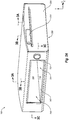
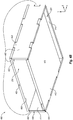
- Figs. 2A-2C illustrate an example cooking device 104 that may be implemented in the cooking systems 100A and 100B of Figs. 1A and 1B in accordance with at least one embodiment described herein.
- Fig. 2A is a perspective view of the cooking device 104
- Fig. 2B is a second perspective view of the cooking device 104
- Fig. 2C is a partially exploded view of the cooking device 104.
- the cooking device 104 may generally be configured to receive thermal energy from an external heat source such as the external heat source 102 of Figs. 1A and 1B , and to transfer the thermal energy to foodstuffs positioned inside the cooking device 104.
- the cooking device 104 may be suitable for cooking foodstuffs that are properly cooked in a high-heat environment through efficient retention and transfer of thermal energy to the foodstuffs.
- the cooking device 104 may be configured to substantially surround foodstuffs while foodstuffs are positioned inside the cooking device 104 and may use a combination of thermal conduction, thermal convection, and thermal radiation to heat the foodstuffs.
- the cooking device 104 may include a refractory oven 202.
- the refractory oven 202 may be used in combination with a housing 206 or may be used without the housing 206.
- the refractory oven 202 may be positioned on the grilling surface 114 of the external heat source 102 without the housing 206.
- the lid 112 may be placed in the closed position over the refractory oven 202, may be placed in a partially closed position, may be left in the open position, or aluminum foil may be used to cover the refractory oven 202.
- the refractory oven 202 may receive thermal energy from the external heat source 102.
- the refractory oven 202 may be positioned within the housing 206.
- the refractory oven 202 and the housing 206 may then be positioned on the grilling surface 114 as shown in Fig. 1B .
- the housing 206 when the housing 206 is used with the refractory oven 202, the housing 206 may at least partially surround the refractory oven 202. In some embodiments, the refractory oven 202 may be introduced into the housing 206 through a bottom opening 208. With reference to Figs. 2B and 2C , for instance, with the housing 206 held in a constant position, the refractory oven 202 may be moved in the arbitrarily defined positive y-direction and thus be introduced into the housing 206.
- one or more support braces 218 may be included in the cooking device 104.
- the one or more support braces 218 ( Figs. 2B and 2C only) may be configured to at least partially secure the refractory oven 202 to the housing 206. Additionally, the support braces 218 may lift the refractory oven 202 some distance off a grilling surface. For example, with combined reference to Figs. 1B , 2B , and 2C , when the cooking device 104 is positioned on the grilling surface 114, the support braces 218 may lift the refractory oven 202 a distance from the grilling surface 114. For example, a bottom surface 220 ( Fig.
- the support braces 218 may be in contact with the grilling surface, which may lift the refractory oven 202 the distance from the grilling surface. In this and other examples, the distance may be about equal to a height 222 ( Figs. 2B and 2C only) of the support braces 218.
- a portion of the thermal energy that may have otherwise been received by the refractory oven 202 may escape to a surrounding environment and/or be received by a heated volume 210 (discussed below), which may be defined between the housing 206 and the refractory oven 202. Additionally, lifting the refractory oven 202 from the grilling surface 114 may decrease wear imposed on the grilling surface 114 that may result from having the refractory oven 202, after being heated, in direct contact with the grilling surface 114.
- the cooking device 104 may generally define two volumes.
- a first volume which is referred to herein as a cooking chamber 204, may be defined by the refractory oven 202.
- the cooking chamber 204 may include a volume that is substantially bordered by an internal surface 226 and a cooking surface 216 of the refractory oven 202.
- the cooking chamber 204 may be configured to receive thermal energy from an external heat source (e.g., the external heat source 102 of Figs. 1A and IB). In some embodiments, the cooking chamber 204 may receive multiple types of thermal energy, which may be transferred to foodstuffs that are positioned inside the cooking chamber 204.
- the refractory oven 202 may be configured to absorb and to retain thermal energy in the structure of the refractory oven 202. The internal surface 226 of the refractory oven 202 may then transfer the absorbed thermal energy to foodstuffs positioned therein via thermal radiation. Additionally, when foodstuffs are positioned inside the refractory oven 202, the foodstuffs may be positioned in contact with the cooking surface 216.
- thermal energy may be transferred to the foodstuffs via thermal conduction.
- a heated gas may be passed over the foodstuffs. Thermal energy in the heated gas may be transferred to the foodstuffs via thermal convection.
- the heated gas may include heated ambient air and/or exhaust gases that may result from combustion of a flammable gas, charcoal, wood, wood pellets, etc.
- the refractory oven 202 may define an opening 250 and a vent 224.
- the opening 250 may be configured to allow foodstuffs to be introduced into and removed from the cooking chamber 204.
- the vent 224 may be positioned in relationship to the opening 250 to receive a portion of the thermal energy in a heated gas into the cooking chamber 204 and to allow the portion of the heated gas to flow across the foodstuffs toward the opening 250.
- the opening 250 may be configured to allow the portion of the thermal energy to exit the cooking chamber 204.
- the opening 250 may be left open or may be selectively covered by a door (not shown). In embodiments without a door, or positioning the door in an open position, may allow monitoring and adjustment of foodstuffs through the opening 250.
- the opening 250 may be positioned opposite the vent 224.
- the vent 224 may allow a heated gas to enter the cooking chamber 204 then pass over foodstuffs positioned inside the refractory oven 202.
- the opening 250 may be configured to allow the heated gas or thermal energy included therein to exit the cooking chamber 204. As the heated gas passes over the foodstuffs positioned between the vent 224 and the opening 250, thermal energy may be transferred to the foodstuffs via thermal convection.
- the refractory oven 202 defines one vent 224, the vent 224 is substantially rectangular, the vent 224 spans essentially a width of the refractory oven 202, and the vent 224 is defined towards a rear portion (opposite the opening 250) of the refractory oven 202.
- the heated gas may exit through the opening 250.
- this is not meant to be limiting.
- the heated gas may exit through one or more other openings and/or one or more vents defined in the refractory oven 202.
- the second volume included in the cooking device 104 which is referred to herein as the heated volume 210, may be defined by the housing 206 and the refractory oven 202.
- the heated volume 210 may be defined between an external surface 212 ( Figs. 2B and 2C only) of the refractory oven 202 and an internal surface 214 ( Figs. 2B and 2C only) of the housing 206.
- the heated volume 210 may also be defined to be bordered by the bottom opening 208 of the housing 206.
- the heated volume 210 may be configured to receive thermal energy from an external heat source.
- the internal surface 214 of the housing 206 and the external surface 212 of the refractory oven 202 are separated by distances 228.
- the distances 228 run may along the length 230 of the housing 206, which creates may an area of the bottom opening 208 in which thermal energy enters the heated volume 210.
- a portion of the grilling surface 114 may be positioned beneath the area of the bottom opening 208 between the internal surface 214 of the housing 206 and the external surface 212 of the refractory oven 202.
- the external heat source 102 may accordingly transfer thermal energy to the heated volume 210.
- the distances 228 may be essentially constant along the length 230 of the housing 206. However, in some alternative embodiments, the distances 228 may vary along the length of the housing 206. The distances 228 may be based on the shapes of the refractory oven 202 and the housing 206, for instance. Additionally, in this and other embodiments, the refractory oven 202 and the housing 206 may be configured such that the distances 228 may only exist on a left side, which is generally indicated in Fig. 2B by 252, and a right side, which is generally indicated in Fig. 2B by 254, of the refractory oven 202.
- the refractory oven 202 and the housing 206 may be configured such that distances 228 may exist on the left side 252, the right side 254, a front, which is generally indicated in Fig. 2B by 256, a back, which is generally indicated in Fig. 2B by 258, or any combination thereof. Additionally, in this and other embodiments, the distances 228 may be essentially equal on the left side 252 and on the right side 254 of the refractory oven 202, which may essentially center the refractory oven 202 with respect to the housing 206 in the x-direction. However, in some embodiments, the distances 228 on the right side 254 of the refractory oven 202 may be different from the left side 252 of the refractory oven 202.
- the heated volume 210 may be configured to reduce the transfer of thermal energy from the cooking chamber 204 through the refractory oven 202.
- the structure of the refractory oven 202 may absorb thermal energy, which may be transferred to foodstuffs through thermal radiation.
- the thermal energy absorbed by the thermal energy may be retained in the structure of the refractory oven 202.
- the cooking device 104 may be generally rectangular.
- the refractory oven 202 may include substantially rectangular surfaces (e.g., 212, 216, and 226) and the bottom opening 208 into which the refractory oven 202 may be introduced may be substantially rectangular.
- the rectangular shape of the cooking device 104 may correspond to external heating devices that include grilling surfaces (e.g., the grilling surface 114 of Fig. 1B ) that may be rectangular. Accordingly, the cooking device 104 may receive thermal energy from a substantial portion of a grilling surface and/or may not hang off the edges of the grilling surface.
- the cooking device 104 may be generally circular, oval, square, or "D"-shaped.
- the vent 224, the opening 250, the distances 228, the heated volume 210, the cooking chamber 204, etc. may include different shapes than those shown in Figs. 2A-2C , and may perform one or more similar functions.
- the cooking device 104 may include one or more thermometers 232.
- the thermometer 232 may be used to monitor the temperature of the heated volume 210 and/or the cooking chamber 204.
- the thermometer 232 may include a bi-metal thermometer, an infrared thermometer, a resistance thermometer, a thermocouple, a pyrometer, or any other type of suitable temperature measuring device.
- the cooking device 104 may include one or more lid supports 234.
- the lid supports 234 may be used to support a lid such as the lid 112 of Fig. 1B .
- the lid may be positioned in a partially closed position in which the lid rests on the lid supports 234.
- the cooking device 104 may include a firebox (not shown).
- the firebox may be constructed from expanded sheet metal, perforated metal, or the like.
- the firebox may be positioned in the cooking chamber 204.
- a fire may be started in the firebox to introduce additional radiant heating to foodstuffs positioned in the cooking chamber 204.
- the firebox may be configured to receive woods or wood chips that may be used to introduce smoke into the cooking chamber 204. The smoke may flavor the foodstuffs.
- the refractory oven 202 may be composed of a material selected for thermal conductivity, strength, density, and thermal shock resistance properties.
- the refractory oven 202 may be composed of Cordierite and FibraMent.
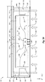
- Figs. 3A-3C are sectional views of the cooking device 104 that illustrate example thermodynamic characteristics of the cooking device 104 in accordance with at least one embodiment described herein.
- Fig. 3A is a sectional view generated using a first plane labeled 3A in Fig. 2A .
- Fig. 3B is a second sectional view generated using a second plane labeled 3B in Fig. 2A .
- Fig. 3C is a third sectional view generated using a third plane labeled 3C in Fig. 2A .
- the first, second, and third sectional views are substantially orthogonal to one another.
- Figs 3A-3C illustrate the cooking device 104 described with reference to Figs. 1A-2C .
- Figs. 3A-3C multiple components and features (e.g., 202, 204, 206, 208, 224, 228, 230, and 250) described with reference to Figs. 1A-2C are included in Figs. 3A-3C . Some details of these components and features are not repeated with reference to Figs. 3A-3C .
- thermal energy is may transferred from an external heat source to the cooking device 104.
- the thermal energy transferred from the external heat source is represented in Figs. 3A and 3B by block arrows 302.
- the thermal energy 302 is received by the refractory oven 202 and the heated volume 210.
- the thermal energy 302 received by the refractory oven 202 may be used to heat foodstuffs 304 positioned within the cooking chamber 204 and the thermal energy 302 received by the heated volume 210 may be used to reduce thermal energy transfer from the cooking chamber 204 through the refractory oven 202.
- heating the foodstuffs 304 may occur in multiple modes of thermal energy transfer.
- the multiple modes of thermal energy transfer may combine to create a high-heat environment in the cooking chamber 204 as well as combine to heat the foodstuffs 304 while positioned inside the cooking chamber 204.
- a first mode may include thermal radiation.
- the thermal radiation is represented in Figs. 3A-3C by dashed, curved, thin arrows 306.
- thermal radiation 306 may occur when the refractory oven 202 absorbs thermal energy.
- the thermal radiation 306 may be emitted by the internal surface 226 and/or the cooking surface 216 of the refractory oven 202.
- thermal energy may be transferred to the foodstuffs 304 via thermal radiation 306 that may originate throughout the refractory oven 202. Accordingly, a substantial portion of the foodstuffs 304 and/or multiple surfaces of the foodstuffs 304 may be heated by the thermal radiation 306.
- a second mode of thermal energy transfer may include thermal conduction.
- the thermal conduction is represented by solid arrows 308.
- thermal conduction 308 may occur when two objects having differing temperatures contact one another.
- the foodstuffs 304 may be positioned to contact the cooking surface 216.
- the cooking surface 216 may have been heated by the thermal energy 302 received from the external heat source. Accordingly, when the foodstuffs 304 contacts the cooking surface 216, the cooking surface 216 may transfer thermal energy to the foodstuffs 304 via thermal conduction 308.
- a third mode of thermal energy transfer may include thermal convection.
- the thermal convection is represented by dashed, curved thick arrows 310.
- thermal convection 310 may occur when a heated gas moves through the cooking chamber 204.
- the thermal energy 302 may heat air or another gas in the cooking chamber 204 or may emit a heated fluid.
- the heated gas may enter the cooking chamber 204 through the vent 224 and exit the cooking chamber 204 through the opening 250. As the heated gas passes over and/or around the foodstuffs 304, thermal energy may be transferred to the foodstuffs via thermal convection 310.
- the heated volume 210 includes a volume that partially surrounds the refractory oven 202. Specifically, the heated volume 210 includes multiple sub-volumes 318, 320, and 322. As best illustrated in Fig. 3A , the sub-volumes 318, 320, and 322 are each heated by the thermal energy 302 received from the external heat source.
- a first sub-volume 318 of the heated volume 210 may be defined between a first panel 326 of the housing 206, a first side portion 324 of the refractory oven 202, and a top cover 332 of the housing 206.
- the first sub-volume 318 may include a width substantially equal to the distance 228, a height substantially equal to a height 314 of the housing 206, and a length substantially equal to the length 230 of the housing 206.
- the height 314 of the housing 206 may vary along the length 230.
- a second sub-volume 320 may be defined between a second panel 328 of the housing 206, a second side portion 330 of the refractory oven 202, and a top cover 332 of the housing 206.
- the second sub-volume 320 may include a width substantially equal to the distance 228, a height substantially equal to the height 314 of the housing 206, and a length substantially equal to the length 230 of the housing 206.
- a third sub-volume 322 is defined between the first and second sub-volumes 318 and 320 and between a top portion 334 of the refractory oven 202 and the top cover 332 of the housing 206.
- a second distance 312 is defined as a distance between the top portion 334 and the top cover 332.
- the top cover 332 is curved in the yz-plane, thus the second distance 312 (and the height 314 of the housing 206) varies along the length 230 of the housing 206 and is constant along a width 316 of the housing 206.
- the thermal energy 302 may enter the first and second sub-volumes 318 and 320. The thermal energy 302 may then heat the third sub-volume 322.
- the heated volume 210 may reduce transfer of thermal energy from the cooking chamber 204 through the refractory oven 202.
- the heated volume 210 may be heated to reduce a thermal gradient between the cooking chamber 204 and the heated volume 210 across the top portion 334. Thus, thermal energy transfer through the top portion 334 may be reduced.
- the heated volume 210 additionally reduces a thermal gradient within the cooking chamber 204.
- thermal energy may be lost through the refractory oven 202. Consequently, the top portion 334, the first side portion 324, and the second side portion 330, other portions, or some combination thereof of the refractory oven 202 may be at a low temperature when compared to a bottom portion 336 of the refractory oven 202.
- the lower temperatures of some portion of the refractory oven 202 may create temperature gradients within the cooking chamber 204.
- the lower temperature of the top portion 334, the first side portion 324, and the second side portion 330 may reduce the transfer of thermal energy to the foodstuffs 304 via the thermal radiation 306.
- configurations of the heated volume 210 and/or the cooking chamber 204 may control one or more thermal characteristics of the cooking device 104.
- the configurations of the heated volume 210 and/or the cooking chamber 204 may determine the distance 228, the second distance 312, a variation of the distances 228 along the length 230, a variation of the second distance 312 along the width 316 and/or the length 230, or some combination thereof.
- the distances 228 and the second distance 312 may be configured such that when the cooking surface 216 is above about 315,56 degrees Celsius (600 degrees Fahrenheit), the temperature gradients within the cooking chamber 204 may be maintained between about 75% and about 100% of the temperature of the cooking surface 216.
- the heated volume 210 and/or the cooking chamber 204 may be configured to maintain the temperatures of the refractory oven 202 within about 37,78 degrees Celsius (100 degrees Fahrenheit) when the cooking surface 216 is between about 315,56 degrees Celsius (600 degrees Fahrenheit) and about 593,33 degrees Celsius (1100 degrees Fahrenheit).
- the housing 206 may be separated from the refractory oven 202 along the side portions 324 and 330 and the top portion 334, thereby creating the heated volume 210. Additionally, the housing 206 may be substantially adjacent to the refractory oven 202 along a rear portion 340 and around a perimeter of the opening 250. In these and other embodiments, the heated volume 210 may, accordingly, not include sub-volumes along the rear portion 340 and/or around the perimeter of the opening 250. However, this configuration of the heated volume 210 is not meant to be limiting. In some alternative embodiments, the heated volume 210 may include sub-volumes along the rear portion 340 and/or around the perimeter of the opening 250.
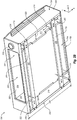
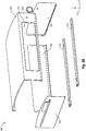
- Figs. 4A-4C illustrate an example refractory oven 400 that may be implemented in the cooking device 104 of Figs. 2A-2C in accordance with at least one embodiment described herein.
- the refractory oven 400 may be substantially similar to the refractory oven 202 discussed with reference to Figs. 2A-3C .
- the refractory oven 400 may define the cooking chamber 204, the vent 224, and the opening 250.
- the refractory oven 400 may receive thermal energy from an external heat source such as the external heat source 102 of Figs. 1A and 1B .
- Some details of the cooking chamber 204, the vent 224, and the opening 250 or the general functions of the refractory oven 400 are not repeated with reference to Figs. 4A-4C .
- the refractory oven 400 includes a refractory top piece 406, two refractory side pieces 408 and 412, a refractory rear piece 414, and a refractory bottom piece 410 (collectively, refractory pieces).
- the refractory top piece 406 may be substantially similar to and/or correspond to the top portion 334
- two refractory side pieces 408 and 412 may be substantially similar to and/or correspond to two side portions 324 and 330
- the refractory bottom piece 410 may be substantially similar to and/or correspond to the bottom portion 336
- the refractory rear piece 414 may be substantially similar to and/or correspond to the rear portion 340, or any combination thereof.
- the refractory top piece 406, the two refractory side pieces 408 and 412, the refractory rear piece 414, and the refractory bottom piece 410 are combined to define the cooking chamber 204.
- the refractory bottom piece 410 may include the cooking surface 216 described above and a heated surface 416 ( Fig. 4B only).
- the heated surface 416 may be oriented towards the external heat source.
- the vent 224 is defined between an end surface 418 ( Fig. 4C only) of the refractory bottom piece 410 and the refractory rear piece 414.
- the opening 250 is defined opposite the refractory rear piece 414. As above, the opening 250 is configured to enable introduction and removal of foodstuffs from the cooking chamber 204 and to allow thermal energy to exit the cooking chamber 204.
- the refractory bottom piece 410 is configured to absorb a first portion of the thermal energy received from the external heat source.
- the refractory bottom piece 410 is further configured to transfer the absorbed first portion of the thermal energy to foodstuffs in contact with the refractory bottom piece 410 via thermal conduction.
- the refractory top piece 406, the two refractory side pieces 408 and 412, and the refractory rear piece 414 are configured to absorb a second portion of the thermal energy received from the external heat source.
- the refractory top piece 406, the two refractory side pieces 408 and 412, and the refractory rear piece 414 are configured to transfer the absorbed thermal energy to the foodstuffs via thermal radiation.
- vent 224 is configured to receive a third portion of the thermal energy from the external heat source as it enters the cooking chamber 204.
- the thermal energy is then transferred to the foodstuffs via thermal convection.
- the thermal energy may be transferred to the refractory top piece 406, the two refractory side pieces 408 and 412, the refractory rear piece 414, and/or the refractory bottom piece 410 via thermal convection. Additionally or alternatively, the thermal energy may exit the cooking chamber 204 through the opening 250.
- one or more of the refractory pieces may be secured to one another.
- one or more of the refractory pieces may include interlocking protrusions 428 ( Fig. 4C only) and slots 430 ( Figs. 4B and 4C only) that may enable the refractory pieces to be secured with respect to one another.
- the refractory bottom piece 410 is secured to the two refractory side pieces 408 and 412
- the refractory top piece 406 is secured to the two refractory side pieces 408 and 412
- the refractory rear piece 414 is secured to the two refractory side pieces 408 and 412.
- one or more of the refractory pieces may be a single piece.
- the two refractory side pieces 408 and 412, the refractory top piece 406, and the refractory rear piece 414 may be a single piece referred to as a refractory enclosure 402 ( Fig. 4B only).
- the interlocking protrusions 428 and the slots 430 between the two refractory side pieces 408 and 412, the refractory top piece 406, and the refractory rear piece 414 may be omitted and the refractory enclosure 402 may be manufactured as a single piece.
- the refractory enclosure 402 may be positioned with respect to the refractory bottom piece 410 to define the cooking chamber 204.
- the refractory enclosure 402 may be positioned with respect to the refractory bottom piece 410 such that the internal surface 226 of the refractory enclosure 402 and a cooking surface 216 of the refractory bottom piece 410 define the cooking chamber 204.
- the refractory enclosure 402 may include another combination of the refractory pieces, without limitation.
- the refractory oven 400 is substantially rectangular. Specifically, the refractory bottom piece 410, the two refractory side pieces 408 and 412, the refractory top piece 406 and the refractory rear piece 414 are substantially rectangular. As used herein with reference to the refractory oven 400, the term "substantially rectangular" may refer to the overall or general shape of the refractory oven 400 or the refractory pieces 410, 408, 412, 406, and 414, which may include the interlocking protrusions 428 and the slots 430. However, this is not meant to be limiting. In some alternative embodiments, the refractory oven 400 may take other shapes such as a dome or pyramidal shaped.
- one or more of the refractory bottom piece 410, the two refractory side pieces 408 and 412, the refractory top piece 406 and the refractory rear piece 414 may be curved and/or non-rectangular.
- one or more of the refractory pieces may be composed of a material selected for thermal conductivity, strength, density, and thermal shock resistance properties.
- one or more of the refractory pieces may be composed of Cordierite and FibraMent.
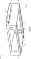
- Figs. 5A and 5B illustrate an example housing 500 that may be implemented in the cooking device 104 of Figs. 2A-2C in accordance with at least one embodiment described herein.
- Fig. 5A is a perspective view of the housing 500
- Fig. 5B is a partially exploded view of the housing 500.
- the housing 500 may be substantially similar to and/or correspond to the housing 206 of Figs. 2A-3C . Accordingly, one or more components or features (e.g., 218) of the housing 206 may be included in the housing 500. Some details of these components and features are not repeated with reference to Figs. 5A and 5B .
- the housing 500 may be configured to surround or partially surround a refractory oven such as the refractory oven 400 of Figs. 4A-4C and/or the refractory oven 202 of Figs. 2A-3C .
- the housing 500 may be composed of a metal.
- the housing 500 may be composed of a carbon steel or an aluminum.
- the housing 500 or some portion thereof may be composed of a ceramic material.
- some alternative embodiments may include a metallic housing 500 that is coated with insulation and/or includes insulative inserts that are attached or affixed to the metallic housing 500.
- the housing 500 may include one or more panels 502, 504, 506, 508, and 510 that may be attached and/or formed as a single piece.
- the housing 500 may include a front panel 504, a rear panel 508, two side panels 506 and 510, and a top cover 502.
- the top cover 502 and the front panel 504 may be formed as a single piece in this and other embodiments, and the rear panel 508 and the two side panels 506 and 510 may be attached to the top cover 502 and the front panel 504 using one or more fasteners.
- This configuration of the housing 500 is not limiting.
- two or more of the panels 502, 504, 506, 508, and 510 may be formed as a single piece and/or attached to the remaining panels 502, 504, 506, 508, and 510 without limitation. Additionally, the panels 502, 504, 506, 508, and 510 may be attached to one another through any suitable means such as welding, adhering with adhesives, end rolling, etc.
- the front panel 504 may define a front panel opening 512.
- the front panel opening 512 may be configured to correspond to an opening defined in a refractory oven.
- the front panel opening 512 may correspond to the opening 250 defined by the refractory oven 400.
- the front panel 504 may be positioned substantially adjacent to a front surface 424 of the refractory bottom piece 410, front surfaces 422 and 426 of the two refractory side pieces 408 and 412, and a front surface 420 of the refractory top piece 406.
- the rear panel 508 may be positioned substantially adjacent to the refractory rear piece 414
- the two side panels 506 and 510 may be positioned a distance (e.g., the distance 228 of Figs. 2A-3C ) from the two refractory side pieces 408 and 412
- the top cover 502 may be positioned a second distance (e.g., the second distance 312 of Figs. 3A-3C ) from the external surface 212 of the refractory top piece 406.
- the housing 500 may surround the external surface 212 of the refractory top piece 406, the two refractory side pieces 408 and 412, and the refractory rear piece 414.
- the housing 500 combined with the refractory top piece 406, the two refractory side pieces 408 and 412, and the refractory rear piece 414, may define a heated volume (discussed above) that may be configured to reduce transfer of thermal energy from the cooking chamber through the refractory top piece 406, the two refractory side pieces 408 and 412, and the refractory rear piece 414.
- the two refractory side pieces 408 and 412 and the two side panels 506 and 510 may be substantially parallel when the refractory oven 400 is positioned inside the housing 500.
- the refractory oven 400 and the housing 500 are generally rectangular. However, this is not meant to be limiting.
- the refractory oven 400 and/or the housing 500 may be circular, oval, D-shaped, etc.
- refractory side pieces of a refractory oven may be substantially parallel to the side panels of a housing.
- the support braces 218 may be attached to the two side panels 506 and 510.
- the support braces 218 may additionally or alternatively be attached to any other of the panels 502, 504, 506, 508, and 510 or may be omitted in some embodiments.
Landscapes
- Engineering & Computer Science (AREA)
- Food Science & Technology (AREA)
- Chemical & Material Sciences (AREA)
- Combustion & Propulsion (AREA)
- Mechanical Engineering (AREA)
- General Engineering & Computer Science (AREA)
- Life Sciences & Earth Sciences (AREA)
- Baking, Grill, Roasting (AREA)
- Electric Stoves And Ranges (AREA)
Claims (7)
- Garvorrichtung (104), umfassend:einen feuerfesten Ofen (202; 400), der eine Garkammer (204) definiert, die durch ein feuerfestes Oberteil (406), zwei feuerfeste Seitenteile (408; 412), ein feuerfestes Hinterteil (414) und ein feuerfestes Unterteil (410) definiert ist, wobei die Garkammer (204) für den Empfang von Wärmeenergie von einer externen Hitzequelle (102) gestaltet ist, wobei das feuerfeste Unterteil (410) an den beiden feuerfesten Seitenteilen (408, 412) gesichert ist, und wobei das feuerfeste Oberteil (406) an den beiden feuerfesten Seitenteilen (408, 412) gesichert ist, und wobei das feuerfeste Hinterteil (414) an den beiden feuerfesten Seitenteilen (408; 412) gesichert ist;eine Öffnung (250), die durch den feuerfesten Ofen (202; 400) definiert ist, wobei sie so gestaltet ist, dass sie es ermöglicht, dass Nahrungsmittel in die Garkammer (204) eingeführt werden, wobei der feuerfeste Ofen (202; 400) ferner so gestaltet ist, dass er die Nahrungsmittel im Wesentlichen umgibt, während die Nahrungsmittel in der Garkammer (204) positioniert sind, wobei die Öffnung (250) gegenüber dem feuerfesten Hinterteil (414) definiert ist, wobei die Öffnung (250) so gestaltet ist, dass sie das Einführen und Entfernen von Nahrungsmitteln in und aus der Garkammer (204) ermöglicht und dass sie aus Austreten von Wärmeenergie aus der Garkammer (204) ermöglicht;eine einzelne Lüftungsöffnung (224), die zwischen einer Stirnfläche des feuerfesten Unterteils (410) und dem feuerfesten Hinterteil (414) definiert ist, wobei sich die Lüftungsöffnung über eine Breite des feuerfesten Ofens erstreckt, und wobei die Lüftungsöffnung im Wesentlichen rechteckig ist;ein Gehäuse (206; 500), das die äußeren Oberflächen des feuerfesten Oberteils (406), der beiden feuerfesten Seitenteile (408; 412) und des feuerfesten Hinterteils (414) wenigstens teilweise umgibt; undein erhitztes Volumen (210), das definiert ist durch das Gehäuse (206; 500) und den feuerfesten Ofen (202, 400) zwischen den äußeren Oberflächen des feuerfesten Oberteils (406), den beiden feuerfesten Seitenteilen (408; 412) und dem feuerfesten Hinterteil (414) und eine innere Oberfläche (214) des Gehäuses (206; 500), wobei das erhitzte Volumen (210) ein erstes Teilvolumen (318), ein zweites Teilvolumen (320) und ein drittes Teilvolumen (322) aufweist, wobei das erhitzte Volumen (210) gestaltet ist für den Empfang von Wärmeenergie von der externen Hitzequelle (102) und für eine Reduzierung der Übertragung von Wärmeenergie von der Garkammer (204) durch das feuerfeste Oberteil (406), die beiden feuerfesten Seitenteile (408; 412) und das feuerfeste Hinterteil (414);wobei:das dritte Teilvolumen (322) zwischen dem ersten Teilvolumen (318) und dem zweiten Teilvolumen (320) definiert ist sowie zwischen einem oberen Teil (334) des feuerfesten Ofens (202) und der oberen Abdeckung (332) des Gehäuses (206);eine innere Oberfläche (214) des Gehäuses (206) und eine äußere Oberfläche (212) des feuerfesten Ofens (202) durch einen seitlichen Abstand getrennt sind, der entlang der Länge des Gehäuses (206) verläuft, und wobei sie Bereiche einer unteren Öffnung (208) erzeugen, durch die Wärmeenergie in das erste Teilvolumen (318) und das zweite Teilvolumen (320) eindringt;die Garvorrichtung (104) für den Empfang von Wärmeenergie von der externen Hitzequelle (102) gestaltet ist, so dass die Wärmeenergie von dem feuerfesten Ofen (202; 400) und dem erhitzten Volumen (210) empfangen wird; wobei das feuerfeste Unterteil (336, 410) so gestaltet ist, dass es einen ersten Teil der von der externen Hitzequelle (102) empfangenen Wärmeenergie absorbiert und den ersten Teil der Wärmeenergie auf Nahrungsmittel über Wärmekonvektion (308) überträgt, die sich in Kontakt mit dem feuerfesten Unterteil befinden;das feuerfeste Oberteil (334, 406), die beiden feuerfesten Seitenteile (324, 330, 408, 412) und das feuerfeste Hinterteil (340, 414) so gestaltet sind, dass sie einen zweiten Teil der von der externen Hitzequelle empfangenen Wärmeenergie empfangen und den zweiten Teil der Wärmeenergie über Wärmestrahlung (306) auf die Nahrungsmittel übertragen; unddie Lüftungsöffnung (224) für den Empfang eines dritten Teils der Wärmeenergie von der externen Hitzequelle in die Garkammer (204) gestaltet ist sowie für die Übertragung des dritten Teils der Wärmeenergie über Wärmekonvektion (310) auf die Nahrungsmittel oder auf das feuerfeste Oberteil, die beiden feuerfesten Seitenteile (324, 330, 408, 412), das feuerfeste Hinterteil (340, 414) und das feuerfeste Unterteil (336, 410), dadurch gekennzeichnet, dass die obere Abdeckung (332) in einer ersten Ebene gekrümmt ist, so dass ein Abstand zwischen dem oberen Teil (334) des feuerfesten Ofens (202) und der oberen Abdeckung entlang einer Länge des Gehäuses variiert und entlang einer Breite (316) des Gehäuses (206) konstant ist.
- Garvorrichtung (104) nach Anspruch 1, wobei:der feuerfeste Ofen (202, 400) eine innere Oberfläche (216, 226) aufweist, die als eine Begrenzung der Garkammer (204) gestaltet ist; undder feuerfeste Ofen (202, 400) für die Übertragung von Wärmeenergie über Wärmestrahlung (306) von der inneren Oberfläche auf die Nahrungsmittel während dem Erhitzen der Nahrungsmittel, während diese sich in der Garkammer (204) befinden, gestaltet ist.
- Garvorrichtung (104) nach Anspruch 2, wobei die Lüftungsöffnung (224) im Verhältnis zu der Öffnung (250) positioniert ist, um einen Teil der Wärmeenergie in einem erhitzten Gas in die Garkammer (204) zu empfangen, um einen Teil der Wärmeenergie in einem erhitzten Gas in die Garkammer (204) zu empfangen, und um es zu ermöglichen, dass das erhitzte Gas über die Nahrungsmittel in Richtung der Öffnung (250) strömt.
- Garvorrichtung (104) nach Anspruch 3, wobei der feuerfeste Ofen eine Garfläche aufweist, auf der die Nahrungsmittel während dem Garen positioniert sind, und die für die Übertragung von Wärmeenergie über Wärmekonvektion (308) auf die Nahrungsmittel gestaltet ist.
- Garvorrichtung (104) nach Anspruch 4, wobei das erhitzte Volumen (210) und die Garkammer (204) so gestaltet sind, dass wenn die Garfläche eine Temperatur zwischen etwa 316 Grad Celsius (600 Grad Fahrenheit) und etwa 593 Grad Celsius (1100 Grad Fahrenhiet) aufweist, ein Temperaturgradient in der Garkammer auf einem Wert zwischen etwa 75% und etwa 100% der Temperatur der Garfläche gehalten wird.
- Garvorrichtung (104) nach Anspruch 1, wobei das Gehäuse (500) folgendes aufweist:eine Vorderplatte (504), die eine Vorderplattenöffnung (512) definiert, die der Öffnung (250) entspricht;eine Rückplatte (508) angrenzend an das feuerfeste Hinterteil (414);zwei Seitenplatten (506, 510), die getrennt von den beiden feuerfesten Seitenteilen (408, 412) positioniert sind, wodurch zwei seitliche Bereiche zwischen den beiden Seitenplatten (506, 510) und den beiden feuerfesten Seitenteilen (408, 412) erzeugt werden; undeine obere Abdeckung (502), die getrennt von der äußeren Oberfläche des feuerfesten Oberteils (406) positioniert ist;wobei das erhitzte Volumen für den Empfang von Wärmeenergie von Bereichen unter den seitlichen Bereichen gestaltet ist.
- Garvorrichtung (104) nach Anspruch 1, wobei das feuerfeste Oberteil (406), die zwei feuerfesten Seitenteile (408; 412), das feuerfeste Hinterteil (414) und das feuerfeste Unterteil (410) im Wesentlichen rechteckig sind.
Priority Applications (1)
| Application Number | Priority Date | Filing Date | Title |
|---|---|---|---|
| EP20150523.7A EP3666138A1 (de) | 2012-07-14 | 2013-07-12 | Feuerfeste garvorrichtung |
Applications Claiming Priority (2)
| Application Number | Priority Date | Filing Date | Title |
|---|---|---|---|
| US201261671725P | 2012-07-14 | 2012-07-14 | |
| PCT/US2013/050350 WO2014014782A1 (en) | 2012-07-14 | 2013-07-12 | Refractory cooking devices |
Related Child Applications (1)
| Application Number | Title | Priority Date | Filing Date |
|---|---|---|---|
| EP20150523.7A Division EP3666138A1 (de) | 2012-07-14 | 2013-07-12 | Feuerfeste garvorrichtung |
Publications (3)
| Publication Number | Publication Date |
|---|---|
| EP2872832A1 EP2872832A1 (de) | 2015-05-20 |
| EP2872832A4 EP2872832A4 (de) | 2016-04-06 |
| EP2872832B1 true EP2872832B1 (de) | 2020-01-08 |
Family
ID=49912863
Family Applications (2)
| Application Number | Title | Priority Date | Filing Date |
|---|---|---|---|
| EP13819686.0A Active EP2872832B1 (de) | 2012-07-14 | 2013-07-12 | Feuerfeste garvorrichtung |
| EP20150523.7A Withdrawn EP3666138A1 (de) | 2012-07-14 | 2013-07-12 | Feuerfeste garvorrichtung |
Family Applications After (1)
| Application Number | Title | Priority Date | Filing Date |
|---|---|---|---|
| EP20150523.7A Withdrawn EP3666138A1 (de) | 2012-07-14 | 2013-07-12 | Feuerfeste garvorrichtung |
Country Status (7)
| Country | Link |
|---|---|
| US (3) | US9491951B2 (de) |
| EP (2) | EP2872832B1 (de) |
| CN (2) | CN104603543B (de) |
| AU (3) | AU2013290471B2 (de) |
| CA (1) | CA2879233C (de) |
| NZ (1) | NZ703555A (de) |
| WO (1) | WO2014014782A1 (de) |
Cited By (2)
| Publication number | Priority date | Publication date | Assignee | Title |
|---|---|---|---|---|
| DE202021106561U1 (de) | 2021-12-01 | 2021-12-17 | Enders Colsman Ag | Lebensmittelgargerät mit einem Strahlungsofen sowie Strahlungsofen für ein Lebensmittelgargerät |
| EP4191140A1 (de) | 2021-12-01 | 2023-06-07 | Enders Colsman AG | Lebensmittelgargerät mit einem strahlungsofen sowie strahlungsofen für ein lebensmittelgargerät |
Families Citing this family (30)
| Publication number | Priority date | Publication date | Assignee | Title |
|---|---|---|---|---|
| CA2879233C (en) * | 2012-07-14 | 2017-10-24 | Timothy M. Case | Refractory cooking devices |
| US9182129B2 (en) | 2013-02-20 | 2015-11-10 | Gri Capital, Llc | System, device, and method for baking a food product |
| US20150323190A1 (en) * | 2014-05-09 | 2015-11-12 | Mark Stein | Refractory cooking chambers |
| USD901228S1 (en) | 2017-07-24 | 2020-11-10 | Regale Microwave Ovens Ltd | Microwave oven cavity liner |
| USD900545S1 (en) * | 2017-07-24 | 2020-11-03 | Regale Microwave Ovens Ltd | Microwave oven cavity liner |
| DE202018006410U1 (de) | 2017-08-09 | 2020-04-23 | Sharkninja Operating Llc | Kochgerät und Komponenten davon |
| EP3460335B1 (de) * | 2017-09-25 | 2021-01-20 | Electrolux Professional S.p.A. | Mit oberschiene ausgestattetes küchengerät zum kochen/erhitzen von lebensmitteln |
| USD914447S1 (en) | 2018-06-19 | 2021-03-30 | Sharkninja Operating Llc | Air diffuser |
| USD934027S1 (en) | 2018-08-09 | 2021-10-26 | Sharkninja Operating Llc | Reversible cooking rack |
| USD883015S1 (en) | 2018-08-09 | 2020-05-05 | Sharkninja Operating Llc | Food preparation device and parts thereof |
| USD903413S1 (en) | 2018-08-09 | 2020-12-01 | Sharkninja Operating Llc | Cooking basket |
| USD883014S1 (en) | 2018-08-09 | 2020-05-05 | Sharkninja Operating Llc | Food preparation device |
| US11452404B2 (en) * | 2018-08-14 | 2022-09-27 | Mark Anderson | Pizza oven |
| WO2020176477A1 (en) | 2019-02-25 | 2020-09-03 | Sharkninja Operating Llc | Cooking system with guard |
| US20190254476A1 (en) | 2019-02-25 | 2019-08-22 | Sharkninja Operating Llc | Cooking device and components thereof |
| USD918654S1 (en) | 2019-06-06 | 2021-05-11 | Sharkninja Operating Llc | Grill plate |
| USD982375S1 (en) | 2019-06-06 | 2023-04-04 | Sharkninja Operating Llc | Food preparation device |
| GB2592290B (en) * | 2020-02-19 | 2024-07-24 | Gozney Group Ltd | Multi-functional open-flame oven |
| US11647861B2 (en) | 2020-03-30 | 2023-05-16 | Sharkninja Operating Llc | Cooking device and components thereof |
| USD992950S1 (en) * | 2020-04-14 | 2023-07-25 | Ooni Limited | Oven |
| USD996121S1 (en) * | 2020-05-22 | 2023-08-22 | Ooni Limited | Oven |
| USD977896S1 (en) * | 2020-05-22 | 2023-02-14 | Ooni Limited | Oven |
| US11344032B1 (en) * | 2021-05-22 | 2022-05-31 | Halo Products Group, Llc | Portable baking oven |
| USD1005769S1 (en) | 2021-09-08 | 2023-11-28 | Newage Products Inc. | Oven |
| US12402631B2 (en) * | 2021-09-08 | 2025-09-02 | Newage Products Inc. | Oven |
| DE102021131733B4 (de) | 2021-12-02 | 2023-06-15 | Enders Colsman Ag | Lebensmittelgargerät |
| USD1047101S1 (en) | 2022-07-28 | 2024-10-15 | Breeo, LLC | Fire pit support |
| US12601497B2 (en) | 2022-07-28 | 2026-04-14 | Breeo, LLC | Fire pit support |
| US20240099512A1 (en) * | 2022-09-27 | 2024-03-28 | Joseph Michael Phillips | Pizza Oven Insert For A Grill |
| USD1101471S1 (en) * | 2024-09-19 | 2025-11-11 | Xinyan Li | Alcohol stove |
Family Cites Families (60)
| Publication number | Priority date | Publication date | Assignee | Title |
|---|---|---|---|---|
| US385348A (en) * | 1887-11-14 | 1888-07-03 | Andbew geisel | |
| US1341299A (en) * | 1918-08-10 | 1920-05-25 | Elyria Iron And Steel Company | Furnace and lining therefor |
| US2243279A (en) * | 1940-03-16 | 1941-05-27 | Herman B Kinney | Cabinet |
| US3035568A (en) * | 1957-02-14 | 1962-05-22 | Frank J Dama | Portable baking device |
| US2920615A (en) * | 1957-06-18 | 1960-01-12 | Gen Electric | Culinary device |
| US3266483A (en) | 1964-08-11 | 1966-08-16 | Keel Adolf | Camp stove toaster |
| US3270740A (en) * | 1964-10-27 | 1966-09-06 | Arthur Tamaroff | Oven |
| CH533444A (de) | 1971-04-13 | 1973-02-15 | Fauser Hans | Vorrichtung zur Zubereitung von Speisen |
| US3777118A (en) | 1971-07-21 | 1973-12-04 | J Creus | Baking oven |
| US3786741A (en) | 1972-08-04 | 1974-01-22 | E Plumley | Smoking and cooking apparatus |
| US4108138A (en) * | 1976-07-01 | 1978-08-22 | Christian Petin | Cooking oven and method of manufacture |
| FR2468839A1 (fr) * | 1979-06-21 | 1981-05-08 | Cazeneuve Didier | Ensemble combine de cuisson d'aliments et chauffage de locaux |
| USD272977S (en) * | 1981-02-23 | 1984-03-13 | Top-Qua & Company Ltd. | Bacon grill |
| US4800865A (en) * | 1988-02-22 | 1989-01-31 | Setzer Michael W | Portable cooking device |
| USD333588S (en) * | 1990-12-03 | 1993-03-02 | Sportmens Specialties, Inc. | Fish smoker |
| GB2263764B (en) * | 1992-02-01 | 1995-09-20 | Peter Derek Howarth | A pizza oven |
| US5195425A (en) * | 1992-04-24 | 1993-03-23 | Modern Home Products Corp. | Rotisserie heat directing device |
| US5413033A (en) * | 1993-10-22 | 1995-05-09 | Riccio; Renato S. | Oven with a stone covered bottom |
| KR0147884B1 (ko) * | 1993-11-11 | 1998-08-17 | 모리시타 요이찌 | 가열조리장치 |
| US6166353A (en) * | 1997-08-22 | 2000-12-26 | White Consolidated Industries, Inc. | Free-standing warmer drawer |
| US6101930A (en) * | 1998-09-16 | 2000-08-15 | Van Over; Charles | Oven insert for improved baking |
| US20020017290A1 (en) * | 1998-12-18 | 2002-02-14 | Hines Robert S. | Cooking grill with baking oven insert |
| US6187359B1 (en) * | 1999-05-12 | 2001-02-13 | Anthony Mark Zuccarini | Method and apparatus for baking foods in a barbeque grill |
| US6041769A (en) * | 1999-07-09 | 2000-03-28 | Llodra, Jr.; Joseph A. | Portable brick oven |
| US6905332B1 (en) | 2000-08-25 | 2005-06-14 | Raypaul Industries, Inc. | Modular oven, panel assembly and method of assembling the same |
| US6307185B1 (en) * | 2000-11-27 | 2001-10-23 | Jerry Loveless | Thermally efficient portable convective oven |
| US6640695B2 (en) | 2002-02-07 | 2003-11-04 | Steven Stark | Pizza insert for barbeque grill |
| EP1534999B1 (de) | 2002-07-05 | 2017-11-01 | TurboChef Technologies, Inc. | Schnellkochofen |
| US6951214B2 (en) | 2003-02-07 | 2005-10-04 | J. W. Beech Pty Ltd | Oven top section and method of construction |
| US8035062B2 (en) * | 2003-07-07 | 2011-10-11 | Turbochef Technologies, Inc. | Combination speed cooking oven |
| US7219663B2 (en) * | 2003-09-05 | 2007-05-22 | Islander Innovations Llc | Kit, apparatus and method for use in cooking over an intense heat source |
| US7086554B2 (en) * | 2003-11-04 | 2006-08-08 | Fmc Technologies, Inc. | Environmentally-controlled food container having fracture resistant seams |
| US20060191528A1 (en) * | 2003-12-19 | 2006-08-31 | Spangrud Bruce D | Gas grill compatible pizza oven |
| JP2006102488A (ja) * | 2004-09-10 | 2006-04-20 | Buckaroo Design:Kk | 携行用調理器具 |
| US20060102167A1 (en) * | 2004-11-15 | 2006-05-18 | Driscoll James P Jr | Pizza oven for grill |
| US7267138B2 (en) * | 2005-02-10 | 2007-09-11 | Jeffrey S Paradis | Manifold cabinet |
| RU2007137495A (ru) | 2005-03-10 | 2009-04-20 | Шелл Интернэшнл Рисерч Маатсхаппий Б.В. (NL) | Система теплопередачи для сгорания топлива и нагревания технологической текучей среды и способ ее использования |
| KR20070120529A (ko) * | 2005-03-14 | 2007-12-24 | 터보쉐프 테크놀러지즈, 아이엔씨. | 공기 튀김기 |
| FR2883363B1 (fr) * | 2005-03-21 | 2007-05-18 | Gerard Melchior Immordino | Four a pizzas mobile et demontable en fonte |
| KR100697022B1 (ko) * | 2005-04-11 | 2007-03-20 | 엘지전자 주식회사 | 조리기기의 컨벡션 챔버 |
| KR100735183B1 (ko) * | 2005-12-28 | 2007-07-03 | 엘지전자 주식회사 | 전기 오븐 |
| JP4627745B2 (ja) * | 2006-06-07 | 2011-02-09 | 日立アプライアンス株式会社 | 加熱調理器 |
| US8464701B2 (en) | 2006-12-21 | 2013-06-18 | Wood Stone Corporation | Chambered flame oven |
| US8578585B2 (en) * | 2007-02-20 | 2013-11-12 | Illinois Tool Works Inc. | Method of manufacturing a modular range system |
| US8291896B1 (en) * | 2007-07-06 | 2012-10-23 | Dynamic Engineering Designs LLC | Outdoor oven and cooking system |
| US8578927B2 (en) * | 2007-09-12 | 2013-11-12 | Willard Gustavsen | High temperature bake oven and method |
| US7686010B2 (en) * | 2007-09-12 | 2010-03-30 | Willard Gustavsen | High temperature bake oven |
| EP2103878B1 (de) * | 2008-03-20 | 2015-04-15 | Candy S.p.A. | Herd mit Befeuchtungsvorrichtung |
| AU2009238211B2 (en) * | 2008-04-17 | 2014-12-04 | Breville Pty Limited | Countertop oven and accessories |
| US20090272728A1 (en) * | 2008-05-01 | 2009-11-05 | Thermoceramix Inc. | Cooking appliances using heater coatings |
| AU2008100666A4 (en) * | 2008-06-29 | 2008-08-21 | Tomic, Tom Mr | Clacker cooler |
| US20100124596A1 (en) * | 2008-11-17 | 2010-05-20 | Randall Warren Nelson | Insulated cover and method for cooking pizza and similar food items on a home gas or charcoal grill |
| US8997639B2 (en) * | 2009-02-03 | 2015-04-07 | Charcoal Companion Incorporated | Smoker box for holding food flavoring wood chips or the like |
| US9668615B2 (en) * | 2010-03-08 | 2017-06-06 | Afc Business Ventures, Llc | Apparatus for converting kettle or kamado style cooking grills for cooking pizza |
| GB2489421B (en) | 2011-03-25 | 2014-07-16 | Daniel Sebastian Chadwick | Oven for baking bread products |
| US9016191B2 (en) * | 2012-04-20 | 2015-04-28 | Robert S. Krolick | Portable baking oven |
| FR2991158B1 (fr) * | 2012-06-05 | 2014-06-20 | L Art Du Jardin | Ensemble de cuisson d'exterieur multifonction |
| US9383108B2 (en) * | 2012-06-27 | 2016-07-05 | Albert Touma | Removable oven for grill |
| CA2879233C (en) * | 2012-07-14 | 2017-10-24 | Timothy M. Case | Refractory cooking devices |
| USD724890S1 (en) * | 2013-05-06 | 2015-03-24 | Sci Direct, Llc | Infrared portable broiler |
-
2013
- 2013-07-12 CA CA2879233A patent/CA2879233C/en active Active
- 2013-07-12 CN CN201380042951.9A patent/CN104603543B/zh not_active Expired - Fee Related
- 2013-07-12 WO PCT/US2013/050350 patent/WO2014014782A1/en not_active Ceased
- 2013-07-12 NZ NZ703555A patent/NZ703555A/en unknown
- 2013-07-12 US US13/941,176 patent/US9491951B2/en active Active
- 2013-07-12 EP EP13819686.0A patent/EP2872832B1/de active Active
- 2013-07-12 EP EP20150523.7A patent/EP3666138A1/de not_active Withdrawn
- 2013-07-12 AU AU2013290471A patent/AU2013290471B2/en active Active
- 2013-07-12 CN CN201610857412.6A patent/CN106333610B/zh not_active Expired - Fee Related
-
2016
- 2016-03-24 US US29/559,153 patent/USD821810S1/en active Active
- 2016-11-14 US US15/350,815 patent/US20170055770A1/en not_active Abandoned
- 2016-12-20 AU AU2016277571A patent/AU2016277571A1/en not_active Abandoned
-
2019
- 2019-01-03 AU AU2019200027A patent/AU2019200027B2/en active Active
Non-Patent Citations (1)
| Title |
|---|
| None * |
Cited By (3)
| Publication number | Priority date | Publication date | Assignee | Title |
|---|---|---|---|---|
| DE202021106561U1 (de) | 2021-12-01 | 2021-12-17 | Enders Colsman Ag | Lebensmittelgargerät mit einem Strahlungsofen sowie Strahlungsofen für ein Lebensmittelgargerät |
| EP4191140A1 (de) | 2021-12-01 | 2023-06-07 | Enders Colsman AG | Lebensmittelgargerät mit einem strahlungsofen sowie strahlungsofen für ein lebensmittelgargerät |
| EP4707674A2 (de) | 2021-12-01 | 2026-03-11 | Enders Colsman AG | Lebensmittelgargerät |
Also Published As
| Publication number | Publication date |
|---|---|
| USD821810S1 (en) | 2018-07-03 |
| US9491951B2 (en) | 2016-11-15 |
| AU2016277571A1 (en) | 2017-01-12 |
| CA2879233A1 (en) | 2014-01-23 |
| NZ703555A (en) | 2016-05-27 |
| CA2879233C (en) | 2017-10-24 |
| AU2019200027A1 (en) | 2019-01-24 |
| CN106333610A (zh) | 2017-01-18 |
| EP2872832A1 (de) | 2015-05-20 |
| CN104603543A (zh) | 2015-05-06 |
| US20140014086A1 (en) | 2014-01-16 |
| WO2014014782A1 (en) | 2014-01-23 |
| CN106333610B (zh) | 2019-04-05 |
| EP3666138A1 (de) | 2020-06-17 |
| AU2013290471A1 (en) | 2015-02-12 |
| US20170055770A1 (en) | 2017-03-02 |
| AU2013290471B2 (en) | 2016-09-22 |
| AU2019200027B2 (en) | 2020-10-08 |
| EP2872832A4 (de) | 2016-04-06 |
| CN104603543B (zh) | 2016-10-26 |
Similar Documents
| Publication | Publication Date | Title |
|---|---|---|
| EP2872832B1 (de) | Feuerfeste garvorrichtung | |
| US20150323190A1 (en) | Refractory cooking chambers | |
| EP1776028B1 (de) | Infrarot emittierende vorrichtung | |
| DK2363645T3 (en) | Oven with radiant tube | |
| KR20170131815A (ko) | 온열 캐비닛이 달린 굽는 장치 | |
| US8291896B1 (en) | Outdoor oven and cooking system | |
| EP3373783B1 (de) | Heiz- und räucherplatten für grill und verfahren | |
| US20060102167A1 (en) | Pizza oven for grill | |
| US9383108B2 (en) | Removable oven for grill | |
| KR101183938B1 (ko) | 다목적 전기 직화 구이기 | |
| WO2006098646A1 (en) | An oven | |
| CN115886595A (zh) | 一种户外烤炉 | |
| JP2010172351A (ja) | 輻射鍋 | |
| KR100610323B1 (ko) | 조리구이판 | |
| US20080083728A1 (en) | Heating element for oven | |
| KR100704443B1 (ko) | 하향 방열식 구이 장치 | |
| US20120167780A1 (en) | Insertable cooking enclosure | |
| JP3173613U (ja) | 無煙炭火焼き器具 | |
| US12303067B2 (en) | Reversible cooking grate | |
| JP3250821U (ja) | バーベキュー用コンロ | |
| JPS589122Y2 (ja) | グリル付テ−ブルコンロ | |
| GR1009680B (el) | Πολυψησταρια | |
| JPH0137548Y2 (de) | ||
| JP3142998U (ja) | 食品用無煙焼き物プレート | |
| JP2013094471A (ja) | 加熱調理器具 |
Legal Events
| Date | Code | Title | Description |
|---|---|---|---|
| PUAI | Public reference made under article 153(3) epc to a published international application that has entered the european phase |
Free format text: ORIGINAL CODE: 0009012 |
|
| 17P | Request for examination filed |
Effective date: 20150210 |
|
| AK | Designated contracting states |
Kind code of ref document: A1 Designated state(s): AL AT BE BG CH CY CZ DE DK EE ES FI FR GB GR HR HU IE IS IT LI LT LU LV MC MK MT NL NO PL PT RO RS SE SI SK SM TR |
|
| AX | Request for extension of the european patent |
Extension state: BA ME |
|
| DAX | Request for extension of the european patent (deleted) | ||
| RA4 | Supplementary search report drawn up and despatched (corrected) |
Effective date: 20160309 |
|
| RIC1 | Information provided on ipc code assigned before grant |
Ipc: F24B 1/00 20060101ALI20160303BHEP Ipc: A47J 37/07 20060101ALI20160303BHEP Ipc: F24C 15/00 20060101AFI20160303BHEP Ipc: F24C 15/08 20060101ALI20160303BHEP Ipc: F24C 3/00 20060101ALI20160303BHEP |
|
| STAA | Information on the status of an ep patent application or granted ep patent |
Free format text: STATUS: EXAMINATION IS IN PROGRESS |
|
| 17Q | First examination report despatched |
Effective date: 20170314 |
|
| RAP1 | Party data changed (applicant data changed or rights of an application transferred) |
Owner name: BAKERSTONE INTERNATIONAL LLC |
|
| RIN1 | Information on inventor provided before grant (corrected) |
Inventor name: CASE, TIMOTHY, M. |
|
| REG | Reference to a national code |
Ref country code: DE Ref legal event code: R079 Ref document number: 602013064923 Country of ref document: DE Free format text: PREVIOUS MAIN CLASS: F24C0015000000 Ipc: F24B0001000000 |
|
| GRAP | Despatch of communication of intention to grant a patent |
Free format text: ORIGINAL CODE: EPIDOSNIGR1 |
|
| STAA | Information on the status of an ep patent application or granted ep patent |
Free format text: STATUS: GRANT OF PATENT IS INTENDED |
|
| RIC1 | Information provided on ipc code assigned before grant |
Ipc: F24B 1/00 20060101AFI20190529BHEP Ipc: A47J 37/06 20060101ALI20190529BHEP Ipc: A47J 37/07 20060101ALI20190529BHEP |
|
| INTG | Intention to grant announced |
Effective date: 20190627 |
|
| GRAS | Grant fee paid |
Free format text: ORIGINAL CODE: EPIDOSNIGR3 |
|
| GRAJ | Information related to disapproval of communication of intention to grant by the applicant or resumption of examination proceedings by the epo deleted |
Free format text: ORIGINAL CODE: EPIDOSDIGR1 |
|
| GRAL | Information related to payment of fee for publishing/printing deleted |
Free format text: ORIGINAL CODE: EPIDOSDIGR3 |
|
| STAA | Information on the status of an ep patent application or granted ep patent |
Free format text: STATUS: EXAMINATION IS IN PROGRESS |
|
| GRAR | Information related to intention to grant a patent recorded |
Free format text: ORIGINAL CODE: EPIDOSNIGR71 |
|
| STAA | Information on the status of an ep patent application or granted ep patent |
Free format text: STATUS: GRANT OF PATENT IS INTENDED |
|
| GRAA | (expected) grant |
Free format text: ORIGINAL CODE: 0009210 |
|
| STAA | Information on the status of an ep patent application or granted ep patent |
Free format text: STATUS: THE PATENT HAS BEEN GRANTED |
|
| INTC | Intention to grant announced (deleted) | ||
| INTG | Intention to grant announced |
Effective date: 20191128 |
|
| AK | Designated contracting states |
Kind code of ref document: B1 Designated state(s): AL AT BE BG CH CY CZ DE DK EE ES FI FR GB GR HR HU IE IS IT LI LT LU LV MC MK MT NL NO PL PT RO RS SE SI SK SM TR |
|
| REG | Reference to a national code |
Ref country code: GB Ref legal event code: FG4D |
|
| REG | Reference to a national code |
Ref country code: CH Ref legal event code: EP |
|
| REG | Reference to a national code |
Ref country code: DE Ref legal event code: R096 Ref document number: 602013064923 Country of ref document: DE |
|
| REG | Reference to a national code |
Ref country code: IE Ref legal event code: FG4D |
|
| REG | Reference to a national code |
Ref country code: AT Ref legal event code: REF Ref document number: 1223177 Country of ref document: AT Kind code of ref document: T Effective date: 20200215 |
|
| REG | Reference to a national code |
Ref country code: NL Ref legal event code: FP |
|
| REG | Reference to a national code |
Ref country code: LT Ref legal event code: MG4D |
|
| PG25 | Lapsed in a contracting state [announced via postgrant information from national office to epo] |
Ref country code: PT Free format text: LAPSE BECAUSE OF FAILURE TO SUBMIT A TRANSLATION OF THE DESCRIPTION OR TO PAY THE FEE WITHIN THE PRESCRIBED TIME-LIMIT Effective date: 20200531 Ref country code: RS Free format text: LAPSE BECAUSE OF FAILURE TO SUBMIT A TRANSLATION OF THE DESCRIPTION OR TO PAY THE FEE WITHIN THE PRESCRIBED TIME-LIMIT Effective date: 20200108 Ref country code: LT Free format text: LAPSE BECAUSE OF FAILURE TO SUBMIT A TRANSLATION OF THE DESCRIPTION OR TO PAY THE FEE WITHIN THE PRESCRIBED TIME-LIMIT Effective date: 20200108 Ref country code: FI Free format text: LAPSE BECAUSE OF FAILURE TO SUBMIT A TRANSLATION OF THE DESCRIPTION OR TO PAY THE FEE WITHIN THE PRESCRIBED TIME-LIMIT Effective date: 20200108 Ref country code: NO Free format text: LAPSE BECAUSE OF FAILURE TO SUBMIT A TRANSLATION OF THE DESCRIPTION OR TO PAY THE FEE WITHIN THE PRESCRIBED TIME-LIMIT Effective date: 20200408 |
|
| PG25 | Lapsed in a contracting state [announced via postgrant information from national office to epo] |
Ref country code: GR Free format text: LAPSE BECAUSE OF FAILURE TO SUBMIT A TRANSLATION OF THE DESCRIPTION OR TO PAY THE FEE WITHIN THE PRESCRIBED TIME-LIMIT Effective date: 20200409 Ref country code: BG Free format text: LAPSE BECAUSE OF FAILURE TO SUBMIT A TRANSLATION OF THE DESCRIPTION OR TO PAY THE FEE WITHIN THE PRESCRIBED TIME-LIMIT Effective date: 20200408 Ref country code: IS Free format text: LAPSE BECAUSE OF FAILURE TO SUBMIT A TRANSLATION OF THE DESCRIPTION OR TO PAY THE FEE WITHIN THE PRESCRIBED TIME-LIMIT Effective date: 20200508 Ref country code: HR Free format text: LAPSE BECAUSE OF FAILURE TO SUBMIT A TRANSLATION OF THE DESCRIPTION OR TO PAY THE FEE WITHIN THE PRESCRIBED TIME-LIMIT Effective date: 20200108 Ref country code: LV Free format text: LAPSE BECAUSE OF FAILURE TO SUBMIT A TRANSLATION OF THE DESCRIPTION OR TO PAY THE FEE WITHIN THE PRESCRIBED TIME-LIMIT Effective date: 20200108 Ref country code: SE Free format text: LAPSE BECAUSE OF FAILURE TO SUBMIT A TRANSLATION OF THE DESCRIPTION OR TO PAY THE FEE WITHIN THE PRESCRIBED TIME-LIMIT Effective date: 20200108 |
|
| REG | Reference to a national code |
Ref country code: DE Ref legal event code: R097 Ref document number: 602013064923 Country of ref document: DE |
|
| PG25 | Lapsed in a contracting state [announced via postgrant information from national office to epo] |
Ref country code: SM Free format text: LAPSE BECAUSE OF FAILURE TO SUBMIT A TRANSLATION OF THE DESCRIPTION OR TO PAY THE FEE WITHIN THE PRESCRIBED TIME-LIMIT Effective date: 20200108 Ref country code: EE Free format text: LAPSE BECAUSE OF FAILURE TO SUBMIT A TRANSLATION OF THE DESCRIPTION OR TO PAY THE FEE WITHIN THE PRESCRIBED TIME-LIMIT Effective date: 20200108 Ref country code: SK Free format text: LAPSE BECAUSE OF FAILURE TO SUBMIT A TRANSLATION OF THE DESCRIPTION OR TO PAY THE FEE WITHIN THE PRESCRIBED TIME-LIMIT Effective date: 20200108 Ref country code: DK Free format text: LAPSE BECAUSE OF FAILURE TO SUBMIT A TRANSLATION OF THE DESCRIPTION OR TO PAY THE FEE WITHIN THE PRESCRIBED TIME-LIMIT Effective date: 20200108 Ref country code: CZ Free format text: LAPSE BECAUSE OF FAILURE TO SUBMIT A TRANSLATION OF THE DESCRIPTION OR TO PAY THE FEE WITHIN THE PRESCRIBED TIME-LIMIT Effective date: 20200108 Ref country code: RO Free format text: LAPSE BECAUSE OF FAILURE TO SUBMIT A TRANSLATION OF THE DESCRIPTION OR TO PAY THE FEE WITHIN THE PRESCRIBED TIME-LIMIT Effective date: 20200108 Ref country code: ES Free format text: LAPSE BECAUSE OF FAILURE TO SUBMIT A TRANSLATION OF THE DESCRIPTION OR TO PAY THE FEE WITHIN THE PRESCRIBED TIME-LIMIT Effective date: 20200108 |
|
| PLBE | No opposition filed within time limit |
Free format text: ORIGINAL CODE: 0009261 |
|
| STAA | Information on the status of an ep patent application or granted ep patent |
Free format text: STATUS: NO OPPOSITION FILED WITHIN TIME LIMIT |
|
| REG | Reference to a national code |
Ref country code: AT Ref legal event code: MK05 Ref document number: 1223177 Country of ref document: AT Kind code of ref document: T Effective date: 20200108 |
|
| 26N | No opposition filed |
Effective date: 20201009 |
|
| PG25 | Lapsed in a contracting state [announced via postgrant information from national office to epo] |
Ref country code: IT Free format text: LAPSE BECAUSE OF FAILURE TO SUBMIT A TRANSLATION OF THE DESCRIPTION OR TO PAY THE FEE WITHIN THE PRESCRIBED TIME-LIMIT Effective date: 20200108 Ref country code: AT Free format text: LAPSE BECAUSE OF FAILURE TO SUBMIT A TRANSLATION OF THE DESCRIPTION OR TO PAY THE FEE WITHIN THE PRESCRIBED TIME-LIMIT Effective date: 20200108 |
|
| PG25 | Lapsed in a contracting state [announced via postgrant information from national office to epo] |
Ref country code: SI Free format text: LAPSE BECAUSE OF FAILURE TO SUBMIT A TRANSLATION OF THE DESCRIPTION OR TO PAY THE FEE WITHIN THE PRESCRIBED TIME-LIMIT Effective date: 20200108 Ref country code: MC Free format text: LAPSE BECAUSE OF FAILURE TO SUBMIT A TRANSLATION OF THE DESCRIPTION OR TO PAY THE FEE WITHIN THE PRESCRIBED TIME-LIMIT Effective date: 20200108 Ref country code: PL Free format text: LAPSE BECAUSE OF FAILURE TO SUBMIT A TRANSLATION OF THE DESCRIPTION OR TO PAY THE FEE WITHIN THE PRESCRIBED TIME-LIMIT Effective date: 20200108 |
|
| REG | Reference to a national code |
Ref country code: CH Ref legal event code: PL |
|
| PG25 | Lapsed in a contracting state [announced via postgrant information from national office to epo] |
Ref country code: CH Free format text: LAPSE BECAUSE OF NON-PAYMENT OF DUE FEES Effective date: 20200731 Ref country code: LI Free format text: LAPSE BECAUSE OF NON-PAYMENT OF DUE FEES Effective date: 20200731 Ref country code: LU Free format text: LAPSE BECAUSE OF NON-PAYMENT OF DUE FEES Effective date: 20200712 |
|
| PG25 | Lapsed in a contracting state [announced via postgrant information from national office to epo] |
Ref country code: IE Free format text: LAPSE BECAUSE OF NON-PAYMENT OF DUE FEES Effective date: 20200712 |
|
| PG25 | Lapsed in a contracting state [announced via postgrant information from national office to epo] |
Ref country code: TR Free format text: LAPSE BECAUSE OF FAILURE TO SUBMIT A TRANSLATION OF THE DESCRIPTION OR TO PAY THE FEE WITHIN THE PRESCRIBED TIME-LIMIT Effective date: 20200108 Ref country code: MT Free format text: LAPSE BECAUSE OF FAILURE TO SUBMIT A TRANSLATION OF THE DESCRIPTION OR TO PAY THE FEE WITHIN THE PRESCRIBED TIME-LIMIT Effective date: 20200108 Ref country code: CY Free format text: LAPSE BECAUSE OF FAILURE TO SUBMIT A TRANSLATION OF THE DESCRIPTION OR TO PAY THE FEE WITHIN THE PRESCRIBED TIME-LIMIT Effective date: 20200108 |
|
| PG25 | Lapsed in a contracting state [announced via postgrant information from national office to epo] |
Ref country code: MK Free format text: LAPSE BECAUSE OF FAILURE TO SUBMIT A TRANSLATION OF THE DESCRIPTION OR TO PAY THE FEE WITHIN THE PRESCRIBED TIME-LIMIT Effective date: 20200108 Ref country code: AL Free format text: LAPSE BECAUSE OF FAILURE TO SUBMIT A TRANSLATION OF THE DESCRIPTION OR TO PAY THE FEE WITHIN THE PRESCRIBED TIME-LIMIT Effective date: 20200108 |
|
| PGFP | Annual fee paid to national office [announced via postgrant information from national office to epo] |
Ref country code: GB Payment date: 20250626 Year of fee payment: 13 |
|
| PGFP | Annual fee paid to national office [announced via postgrant information from national office to epo] |
Ref country code: BE Payment date: 20250626 Year of fee payment: 13 Ref country code: NL Payment date: 20250627 Year of fee payment: 13 |
|
| PGFP | Annual fee paid to national office [announced via postgrant information from national office to epo] |
Ref country code: FR Payment date: 20250623 Year of fee payment: 13 |
|
| PGFP | Annual fee paid to national office [announced via postgrant information from national office to epo] |
Ref country code: DE Payment date: 20250624 Year of fee payment: 13 |