EP2872869B1 - Distribution régulée d'échantillons sur des substrats - Google Patents
Distribution régulée d'échantillons sur des substrats Download PDFInfo
- Publication number
- EP2872869B1 EP2872869B1 EP13742342.2A EP13742342A EP2872869B1 EP 2872869 B1 EP2872869 B1 EP 2872869B1 EP 13742342 A EP13742342 A EP 13742342A EP 2872869 B1 EP2872869 B1 EP 2872869B1
- Authority
- EP
- European Patent Office
- Prior art keywords
- substrate
- sample
- applicator
- fluid
- sample applicator
- Prior art date
- Legal status (The legal status is an assumption and is not a legal conclusion. Google has not performed a legal analysis and makes no representation as to the accuracy of the status listed.)
- Active
Links
Images




Classifications
-
- G—PHYSICS
- G01—MEASURING; TESTING
- G01N—INVESTIGATING OR ANALYSING MATERIALS BY DETERMINING THEIR CHEMICAL OR PHYSICAL PROPERTIES
- G01N1/00—Sampling; Preparing specimens for investigation
- G01N1/28—Preparing specimens for investigation including physical details of (bio-)chemical methods covered elsewhere, e.g. G01N33/50, C12Q
- G01N1/2813—Producing thin layers of samples on a substrate, e.g. smearing, spinning-on
-
- G—PHYSICS
- G01—MEASURING; TESTING
- G01N—INVESTIGATING OR ANALYSING MATERIALS BY DETERMINING THEIR CHEMICAL OR PHYSICAL PROPERTIES
- G01N35/00—Automatic analysis not limited to methods or materials provided for in any single one of groups G01N1/00 - G01N33/00; Handling materials therefor
- G01N35/10—Devices for transferring samples or any liquids to, in, or from, the analysis apparatus, e.g. suction devices, injection devices
- G01N35/1009—Characterised by arrangements for controlling the aspiration or dispense of liquids
-
- G—PHYSICS
- G06—COMPUTING OR CALCULATING; COUNTING
- G06T—IMAGE DATA PROCESSING OR GENERATION, IN GENERAL
- G06T7/00—Image analysis
- G06T7/0002—Inspection of images, e.g. flaw detection
- G06T7/0012—Biomedical image inspection
-
- G—PHYSICS
- G06—COMPUTING OR CALCULATING; COUNTING
- G06T—IMAGE DATA PROCESSING OR GENERATION, IN GENERAL
- G06T7/00—Image analysis
- G06T7/10—Segmentation; Edge detection
- G06T7/13—Edge detection
-
- G—PHYSICS
- G06—COMPUTING OR CALCULATING; COUNTING
- G06T—IMAGE DATA PROCESSING OR GENERATION, IN GENERAL
- G06T7/00—Image analysis
- G06T7/70—Determining position or orientation of objects or cameras
-
- G—PHYSICS
- G06—COMPUTING OR CALCULATING; COUNTING
- G06T—IMAGE DATA PROCESSING OR GENERATION, IN GENERAL
- G06T7/00—Image analysis
- G06T7/70—Determining position or orientation of objects or cameras
- G06T7/73—Determining position or orientation of objects or cameras using feature-based methods
-
- G—PHYSICS
- G06—COMPUTING OR CALCULATING; COUNTING
- G06T—IMAGE DATA PROCESSING OR GENERATION, IN GENERAL
- G06T2207/00—Indexing scheme for image analysis or image enhancement
- G06T2207/10—Image acquisition modality
- G06T2207/10056—Microscopic image
Definitions
- a portioning position specification section specifies a portioning position on an object according to an image of the object such as a membrane displayed on a monitor section
- a portioning control section performs relative positioning between the object and a portioning element so that the specified portioning position on the object is below the portioning element and controls the portioning operation.
- a portioning position information generation section can generate portioning position information on the portioning position on the object specified by the portioning position specification section and subjected to portioning and output it outside.
- the image(s) include both a direct image region that corresponds to a direct (e.g., non-reflected) image of the sample applicator above the substrate, and a first reflected image region that corresponds to an image of the sample applicator that is reflected from the substrate surface.
- the position of the applicator relative to the substrate surface can be determined based on the distance between the edges of the sample applicator in the direct image region and the first reflected image region,
- the methods and the systems that implement the methods can be extended to determine the position of the sample applicator at multiple transverse locations relative to the substrate.
- the disclosure features methods for preparing a sample on a substrate, the methods including: (a) obtaining an image of a sample applicator in proximity to the substrate, the image including a direct image region corresponding to the sample applicator and a first reflected image region corresponding to an image of the sample applicator reflected from a surface of the substrate; (b) determining a position of an edge of the sample applicator in the direct image region; (c) determining a position of a reflected edge of the sample applicator in the first reflected image region; (d) determining a distance between the edge of the sample applicator and the reflected edge of the sample applicator; (e) determining the position of the sample applicator relative to a surface of the substrate based on the distance between the edges; and (f) dispensing the sample onto the substrate using the sample applicator, where during the dispensing the position of the sample applicator relative to the substrate is maintained.
- the sample applicator can be translated relative to the substrate at a speed of between 80 mm/s and 90 mm/s during the dispensing.
- the sample can be dispensed onto the substrate at a rate of 0.05 ⁇ L/s or more.
- the sample can be dispensed onto the substrate in a pattern of adjacent rows, where a separation between adjacent rows during the dispensing is between 0,20 mm and 0.60 mm.
- the sample can include blood and the substrate can be a microscope slide.
- Embodiments of the methods can also include any other features or steps disclosed herein, in any combination, as appropriate.
- Embodiments of the methods can include any one or more of the following features.
- the first image can be located in a first image region of the sample applicator image, and the second image can be located in a second image region different from the first image region of the sample applicator image.
- the first image can be a direct image of the sample applicator, and the second image can be an image of the sample applicator reflected from a surface of the substrate.
- Determining a height of the sample applicator relative to a surface plane of the substrate can include determining a first position of an edge of the sample applicator in the first image, determining a second position of a corresponding edge of the sample applicator in the second image, and determining the height of the sample applicator based on a difference between the first and second positions.
- the substrate can have a rectangular surface formed by orthogonal long and short edges of the substrate, and the methods can include dispensing a plurality of rows of the fluid sample onto the rectangular surface by effecting a relative translation between the sample applicator and the substrate in a direction parallel to the long edges of the rectangular surface.
- the substrate can have a rectangular surface formed by orthogonal long and short edges of the substrate, and the methods can include dispensing a plurality of rows of the fluid sample onto the rectangular surface by effecting a relative translation between the sample applicator and the substrate in a direction parallel to the short edges of the rectangular surface.
- the substrate can have a rectangular surface formed by orthogonal long and short edges of the substrate, and the methods can include dispensing a plurality of rows of the fluid sample onto the rectangular surface by effecting a relative translation between the sample applicator and the substrate at an angle to both the long and short edges of the rectangular surface.
- the target height can be between 9 microns and 15 microns.
- the fluid sample can include blood.
- the methods can include obtaining an image of blood cells from the fluid sample on the substrate, and assessing at least one of a distribution of the blood cells on the substrate and a uniformity of staining of the blood cells on the substrate.
- the methods can include adjusting an operating parameter of a fluid dispensing system that includes the sample applicator based on the at least one of a distribution of the blood cells on the substrate and a uniformity of staining of the blood cells on the substrate.
- the operating parameter can include at least one of a rate at which the fluid sample is dispensed from the sample applicator, and a relative translation speed between the sample applicator and the substrate.
- the fluid sample can be dispensed onto the substrate in a plurality of successive rows, and the operating parameter can include at least one of a spacing between adjacent rows of fluid, and a length of the rows of fluid.
- the operating parameter can include at least one of a temperature of the fluid sample, and a relative humidity within the fluid dispensing system.
- the methods can include effecting a relative translation speed between the sample applicator and the substrate of between 40 mm/s and 90 mm/s to dispense the fluid sample.
- the methods can include dispensing the fluid sample from the sample applicator at a rate of between 0.035 ⁇ L/s and 0.075 ⁇ L/s.
- the methods can include dispensing the fluid sample onto the substrate in a plurality of successive rows, where a spacing between adjacent rows is between 0.20 mm and 0.60 mm.
- the methods can include, before dispensing the fluid sample onto the substrate, obtaining information about the composition of the sample, obtaining a set of pre-defined operating parameters based upon the information, and applying the pre-defined operating parameters to configure a fluid dispensing system comprising the sample applicator.
- Embodiments of the methods can also include any of the other features or steps disclosed herein, in any combination, as appropriate.
- the sample applicator can include an internal fluid transport channel having an inner diameter of between 200 microns and 650 microns.
- the sample applicator can have an outer diameter, and a ratio of the outer diameter to the inner diameter can be is 1.5 or less.
- the target height can be between 9 microns and 15 microns.
- a "direct image region” corresponds to a region in an image that includes a direct image of the sample applicator.
- a direct image is an image that has not been reflected from a surface of the substrate.
- a "first reflected image region” is a region, typically from the same image, that includes an image of the sample applicator that has been reflected from a surface of the substrate (either the upper surface or the lower surface).
- a “second reflected image region” is a region, typically from the same image, that includes an image of the sample applicator that has also been reflected from a surface of the substrate.
- the first and second reflected image regions correspond to images of the sample applicator that have been reflected from different surfaces of the substrate (e.g., the upper and lower surfaces, respectively).
- the average intensity for the subset of pixels with the lowest intensities can correspond to the average of the m smallest pixel intensities for the particular row.
- the values of n and m can be different, or the same.
- n can have a value of 10, but can range from 1 through the total number of pixels for the row.
- m can have a value of 10, but can range from 1 through the total number of pixels for the row.
- the values of n and m are selected for the set of pixels so that none of the pixels selected is common to both the first and second subsets.
- the viscosity and surface tension of blood are both relatively high, the amount of lateral spreading of the dispensed rows is smaller than would occur for rows of a fluid with smaller surface tension, such as water or a sample of blood mixed with a diluent.
- a fluid with smaller surface tension such as water or a sample of blood mixed with a diluent.
- the viscosity and surface tension can be determined and monitored to ensure that the spacing between rows of blood is suitable to achieve the desired overall coverage.
- a substrate such as microscope slides are maintained in an orientation such that the surface of the slide is planar and nominally orthogonal to a central axis of the applicator
- a substrate can be oriented such that its upper surface is angled somewhat with respect to the central axis of the applicator, further complicating the task of maintaining a constant applicator height.
- the applicator can dispense rows of blood without making any further measurements of the applicator height.
- the initial set of height measurements used to determine suitable settings for the applicator manipulator functions as calibration data for the dispensing operation.
- a known quantity of blood can be dispensed continuously (e.g., in rows) without performing applicator height measurements, while enabling a continuous, controlled height adjustment of the applicator to ensure that the blood is dispensed regularly and uniformly, and each row is allowed to dry for the same amount of time before an adjacent row is dispensed.
- This pattern of regular, uniform row dispensing helps to ensure that the resulting blood sample is as uniform as possible when it has dried.
- axis 112 corresponds to a direction along which sample applicator 102 is translated by manipulator 150.
- Manipulator 150 can also translate sample applicator 102 along a second axis orthogonal to the plane of FIG. 1B and to axis 112; substrate 102 can be untilted with respect to the second axis (e.g., as in FIG. 1A ), or substrate 102 can be tilted with respect to the second axis.
- the tilt angle with respect to the second axis can be the same as, or different from, the tilt angle with respect to axis 112.
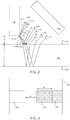
- Portions of rays 110d-f in FIG. 2 undergo refraction rather than reflection at upper surface 102a. These refracted rays propagate through substrate 102, and are reflected from lower surface 102b of substrate 102. Upon encountering upper surface 102a a second time, the rays again undergo refraction at the upper surface, emerge from substrate 102, and propagate toward detector 106 as rays 110j, 110k, and 1101. Rays 110j-1 form a second indirect (e.g., reflected) image of point 100a in a second reflected image region of the image formed on detector 106.
- the reflected image corresponding to rays 110g-i is displaced laterally from the reflected image corresponding to rays 110j-l in the image plane on detector 106 by an amount ⁇ t that is related to the thickness t of substrate 102.
- the displacement ⁇ t is also larger.
- ⁇ t is reduced.
- the height h of sample applicator above substrate 102 and the thickness t of substrate 102 can be estimated. Further, by calibrating image pixel measurements with known linear displacements, pixel-based measurements of height and thickness can be converted into length units (e.g., microns).
- each subset (e.g., column) of pixels identified in step 402 is separately analyzed by calculating an intensity gradient along the column.
- the gradient is calculated along the pixel column using an edge detection kernel (e.g., a four-pixel kernel of [1, 3, -3, -1]).
- the gradient can be calculated by determining the intensity differences between each adjacent pixel in the column.
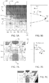
- the change in intensity is plotted along the upper (horizontal) axis against column position on the left-hand (vertical) axis.
- the uppermost plotted point 514 along the vertical axis corresponds to the change in intensity between the first pixel 516 and the second pixel 518 in column 506.
- the vertical coordinate of point 514 corresponds to the dividing line between the pixels; the horizontal coordinate of point 514 corresponds to the calculated change in intensity between the pixels.
- the intensity of second pixel 518 in column 506 is greater than the intensity of first pixel 516 (e.g., the second pixel appears brighter than the first), the change in intensity is positive.
- the largest change in intensity in column 506 occurs between fourth pixel 520 and fifth pixel 522; this change in intensity is represented by point 524 in FIG. 5B .
- step 406 the position of the maximum change in intensity is determined for each pixel column.
- the process of determining the position of the maximum change in intensity is generally accomplished by fitting a functional form to the change in intensity values calculated between adjacent pixels of the column in step 404. This process is illustrated in FIG. 5B , where curve 526 has been fitted to some of the calculated change in intensity values.
- a variety of different functional forms can be used to determine the position of the maximum change in intensity.
- a parabolic functional form was fitted to the maximum change in intensity between adjacent pixels (e.g., point 524) and to the calculated change in intensity values on either side of the maximum. As shown in FIG.
- the apex position of the sample applicator can be further refined by fitting a functional form to the positions of maximum change in intensity for each pixel column.
- a functional form e.g., a parabolic functional form
- the apex of the sample applicator can be determined as the vertex of the fitted parabolic form.
- a parabola fitted to positions 530, 532, 534, 536, 538, and 540 will have a vertex that is approximately coincident with position 540.
- the fitted functional form may not be exactly coincident with the any of the positions of maximum change in intensity for the pixel columns, due to imaging artifacts and irregularities in the shape of sample applicator 100, for example.
- the process shown in FIG. 4 terminates at step 410.
- the next step in determining the position of sample applicator 100 relative to substrate 102 is to determine an apex position for the image of sample applicator 100 that corresponds to the reflection from upper surface 102a of substrate 102.
- FIG. 6 shows a flow chart 600 that includes a series of steps for determining an apex position of a reflected image of the sample applicator.
- the first step 602 in flow chart 600 is to identify the image of the sample applicator that corresponds to the reflection from upper surface 102a of substrate 102.
- the second step 604 in flow chart 600 is to identify rows of pixels that extend in a direction perpendicular to the central axis 108 of sample applicator 100 in the reflected image region,
- the central axis 108 in the first and second reflected image regions extends in a direction parallel to the left- and right-hand edges of image 700; accordingly, suitable rows of pixels extend in a direction parallel to the top and bottom edges of image 700.
- pixel rows can also be foreshortened to speed up computational operations.
- the edge positions of the direct image of the sample applicator can be determined from the analysis of image 704.
- the edge positions of the reflected images 708 and 710 of the sample applicator can be assumed to fall in approximately the same locations as the edge positions of the direct image 704. Accordingly, pixel rows that are used to find the apex position of the reflected image of the sample applicator can be shortened by applying edge boundaries 714 and 716 in FIG. 7A .
- edge boundaries can be selected to exclude other substrate features (e.g., painted logos, specimen frames, fiducial marks) from the first reflected image region.
- the contrast level for each row of pixels is determined in step 606.
- the contrast level can be determined in a variety of ways; the following discussion presents a particular series of steps for performing this calculation, but it is to be understood that other methods can also be used for measuring the variability in intensity for each row of pixels.
- the contrast level for the pixel row is calculated as the difference between the average intensity for the subset of highest intensity pixels for the row, and the average intensity for the subset of lowest intensity pixels for the row. The foregoing process can be repeated for each row of pixels identified in step 604, so that each pixel row has an associated contrast level.
- the foregoing surface touch detection calibration procedure can be performed at initialization of an automated sample preparation system, at predetermined times during normal operation or maintenance of such system, or upon receipt of a system error message relating to the quality of a prepared sample on a substrate (e.g., a low magnification or high magnification imaging station cannot accurately identify or count one or more constituents within a sample).
- a system error message relating to the quality of a prepared sample on a substrate
- sample applicator 100 is maintained at a specific location relative to substrate 102 (e.g., at a particular x- and y-coordinate position in the coordinate system of the manipulator), and the height of sample applicator 100 above substrate 102 is varied (e.g., sample applicator 100 is translated along the z-coordinate direction in the coordinate system of manipulator 150).
- the steps disclosed above in flow charts 400 and 600 are repeated to determine the separation ⁇ h.
- target separation ⁇ h t corresponds to the desired target height h t of sample applicator 100 above substrate 102.
- a target sample applicator height h t above the surface of substrate 102 e.g., 12 microns
- target separation ⁇ h t falls in between measured separations ⁇ h3 and ⁇ h 4 , which correspond to manipulator (or stage) control settings V 3 and V 4 , respectively.
- the formation of the vortex presents a number of obstacles to uniform fluid deposition onto substrate 102.
- rows of fluid dispensed through applicator 100 can be non-uniform, as the distribution of fluid within the row is impacted by recirculation within the vortex.
- certain types of cells such as platelets can be trapped within the vortex, leading to non-uniform deposition of these cells onto substrate 102.
- different types of cells can be trapped by varying degrees within the vortex, so that the distribution of cells in the dispensed fluid on the surface of substrate 102 may no longer reflect the distribution within the bulk fluid.
- a further phenomenon that can affect the quality of the prepared samples is the extent to which the cells aggregate in the sample applicator prior to dispensing onto substrate 102.
- Red blood cells have a weak natural affinity for one another, and tend to aggregate to a higher extent in a fluid richer in red blood cells than in a fluid where they are more dilute.
- clustering and stacking of red blood cells tends to occur to a greater extent in the first few rows of fluid that are dispensed onto substrate 102 than in later rows, because the later rows are dispensed from fluid with a smaller number of cells.
- red blood cell stacking may occur with greater frequency in one portion of the prepared sample than in others, making it more difficult to obtain reliable quantitative analysis results.
- the edges of the deposited rows can appear darker than the central portions due to accumulation of cells in these regions. Further, cells near the edges of the rows can undergo hemolysis and/or lose their natural shape (e.g., the depressed central pallor), so that the shape of the dried cells is no longer representative of the cells in their unaltered state.
- the applicator is maintained within 2 microns (e.g., within 1.7 microns, within 1.5 microns, within 1.3 microns, within 1.0 micron, within 0.8 micron, within 0.6 micron, within 0.4 micron, within 0.2 micron) of the applicator's target height relative to the surface of the substrate.
- FIG. 12B is a schematic diagram showing an end view of a sample applicator 100 with an oval opening 2100 through which fluid is dispensed onto a substrate.
- the minor dimension d of the oval opening is oriented parallel to the direction of translation.
- the minor dimension d can be at least 200 microns (e.g., at least 250 microns, at least 300 microns, at least 400 microns, at least 500 microns), for example.
- the rate at which the sample applicator is translated relative to the surface of the substrate can be increased.
- the sample applicator can be translated relative to the surface of the substrate using a variety of techniques. For example, in some embodiments, stage 152 - which supports the substrate - is translated, while the sample applicator remains essentially fixed in position. In certain embodiments, manipulator 150 translates the applicator while the substrate mounted on stage 152 remains essentially fixed in position.
- both the applicator and the substrate are translated by manipulator 150 and stage 152, respectively.
- manipulator 150 and stage 152 results in translation of the sample applicator relative to the surface of the substrate.
- references to "translating" the applicator imply a relative translation of the applicator with respect to the substrate, and can be implemented by translating the applicator while the substrate remains essentially fixed in position, by translating the substrate while the applicator remains essentially fixed in position, and by translating both the applicator and the substrate.
- Adjusting the row separation can be used to compensate for several phenomena that affect the quality of prepared samples.
- the uniformity of the layer dispensed onto substrate 102 increases.
- shape distortion e.g., loss of central pallor and/or target cell formation.
- row separations of between 0.20 mm and 0.60 mm e.g., between 0.25 mm and 0.55 mm, 0.30 mm and 0.40 mm
- 0.20 mm and 0.60 mm can be used to compensate for such factors.
- Fluids differ in their viscosities, and even different samples of a particular type of fluid such as blood can have different viscosities. Adjusting the row separation can compensate for such variations between samples.
- the adjacent row separation is increased (e.g., the extent of overlap between adjacent rows is reduced) to avoid forming overlapped regions with cell concentrations that are significantly larger than in non-overlapped regions; as more viscous fluids do not flow as freely as less viscous solutions, inhomogeneous distributions of cells on substrate 102 do not disperse as readily as in less viscous solutions). It has been observed that for blood samples in general, a row separation of about 0.4 mm yields rows that flow toward each other and just touch, yielding a highly uniform sample.
- maintaining a "wet edge” refers to adjusting properties of the fluid deposition system to ensure that each row of fluid dries for only a certain length of time before a subsequent row of fluid is dispensed, to ensure that successively dispensed rows flow together to contact one another and leave a distribution of cells on the substrate surface that is relatively uniform on the substrate surface once fluid dispensing is complete and the fluid dries. Because maintaining a "wet edge” is an important aspect to ensure that the deposited cells retain their shape and are distributed homogeneously, adjustment of the row length can be used to directly influence the quality of the samples that are produced.
- row lengths are adjusted so that rows of dispensed fluid occupy a percentage of the available area on the substrate surface.
- the substrate surface is rectangular in shape, and dispensed rows of fluid extend along 60% or more (e.g., 70% or more, 80% or more, 90% or more, 95% or more, 99% or more) of the longer dimension of the rectangular surface.
- the systems disclosed herein can be configured to adjust the row length during dispensing, so that not all rows have the same length. For example, the row length can be changed to account for changes in the composition of the fluid, the temperature, and/or the humidity during fluid deposition.
- the operating parameters are adjusted subject to various constraints.
- the relative humidity and temperature of the systems disclosed herein can be adjusted within certain limits, but neither the humidity nor the temperature can be adjusted without constraint, because the operation of other components in the systems disclosed herein can also be affected by changes in humidity and/or temperature.
- system 50 can include a light source 170 for directing incident light onto sample applicator 100.
- Light source 170 can be electrically connected to control unit 160 as shown in FIG. 1A .
- Light source 170 can include, for example, one or more incandescent, fluorescent, diode-based, and/or laser sources.
- Incident light produced by light source 170 can include wavelengths in one or more of the ultraviolet, visible, and infrared regions of the electromagnetic spectrum.
- a substrate manipulator can transfer the substrate to storage sub-system 1040.
- Storage sub-system 1040 can label individual substrates, for example, with information relating to the source of the sample applied to the substrate, the time of analysis, and/or any irregularities identified during analysis.
- Storage sub-system can also store processed substrates in multi-substrate racks, which can be removed from system 1000 as they are filled with substrates.
- each of the various sub-systems of system 1000 can be linked to a common electronic processor 1050 (which can be the same as electronic processor 162, or a different electronic processor).
- Processor 1050 can be configured to control the operation of each of the sub-systems of system 1000 in automated fashion, with relatively little (or no) input from a system operator.
- Results from the analysis of samples can be displayed on system display 1060 for a supervising operator.
- Interface 1070 permits the operator to issue commands to system 1000 and to manually review the automated analysis results,
Landscapes
- Engineering & Computer Science (AREA)
- General Physics & Mathematics (AREA)
- Physics & Mathematics (AREA)
- General Health & Medical Sciences (AREA)
- Health & Medical Sciences (AREA)
- Computer Vision & Pattern Recognition (AREA)
- Theoretical Computer Science (AREA)
- Pathology (AREA)
- Analytical Chemistry (AREA)
- Biochemistry (AREA)
- Chemical & Material Sciences (AREA)
- Immunology (AREA)
- Life Sciences & Earth Sciences (AREA)
- Nuclear Medicine, Radiotherapy & Molecular Imaging (AREA)
- Medical Informatics (AREA)
- Radiology & Medical Imaging (AREA)
- Quality & Reliability (AREA)
- Sampling And Sample Adjustment (AREA)
- Investigating Or Analysing Biological Materials (AREA)
- Apparatus Associated With Microorganisms And Enzymes (AREA)
- Investigating Or Analysing Materials By Optical Means (AREA)
Claims (16)
- Procédé de distribution d'un échantillon de fluide (104) sur un substrat (102), le procédé comprenant :l'obtention d'une image d'un applicateur d'échantillon (100) à proximité du substrat (102), l'image comprenant une première image (302) de l'applicateur d'échantillon (100) et une deuxième image (304) de l'applicateur d'échantillon (100) ;la détermination d'une hauteur (h) de l'applicateur d'échantillon (100) par rapport à un plan de surface du substrat (102) sur la base d'une distance entre des parties communes des première et deuxième images (302, 304) ; etla distribution de l'échantillon de fluide (104) sur le substrat (102) au moyen de l'applicateur d'échantillon (100), la distribution comprenant :la translation de l'applicateur d'échantillon (100), la translation du substrat (102), ou la translation à la fois de l'applicateur d'échantillon (100) et du substrat (102), pour effectuer une translation relative entre l'applicateur d'échantillon (100) et le substrat (102) ; etle maintien de l'applicateur d'échantillon (100) dans les 2 micromètres d'une hauteur cible par rapport au plan de surface du substrat (102) pendant la translation.
- Procédé de la revendication 1, dans lequel la première image (302) est une image directe de l'applicateur d'échantillon (100), et dans lequel la deuxième image (304) est une image de l'applicateur d'échantillon (100) réfléchie depuis une surface du substrat (102).
- Procédé de la revendication 1, dans lequel la hauteur cible se situe entre 9 micromètres et 15 micromètres.
- Procédé de la revendication 1, dans lequel l'échantillon de fluide (104) comprend du sang.
- Procédé de la revendication 4, comprenant en outre le réglage d'un paramètre de fonctionnement d'un système de distribution de fluide comprenant l'applicateur d'échantillon (100) sur la base d'une répartition des cellules sanguines sur le substrat (102) et/ou d'une uniformité de coloration des cellules sanguines sur le substrat (102),
dans lequel l'échantillon de fluide (104) est distribué sur le substrat (102) en une pluralité de rangées successives, et dans lequel le paramètre de fonctionnement comprend un espacement entre rangées adjacentes de fluide, et/ou une longueur des rangées de fluide. - Procédé de la revendication 4, comprenant en outre le réglage d'un paramètre de fonctionnement d'un système de distribution de fluide comprenant l'applicateur d'échantillon (100) sur la base d'une répartition des cellules sanguines sur le substrat (102) et/ou d'une uniformité de coloration des cellules sanguines sur le substrat,
dans lequel le paramètre de fonctionnement comprend une température de l'échantillon de fluide (104), et/ou une humidité relative à l'intérieur du système de distribution de fluide. - Procédé de la revendication 1, comprenant en outre la distribution de l'échantillon de fluide depuis l'applicateur d'échantillon (100) à une vitesse comprise entre 0,035 µL/s et 0,075 µL/s.
- Procédé de la revendication 1, comprenant en outre la distribution de l'échantillon de fluide (104) sur le substrat (102) en une pluralité de rangées successives, un espacement entre rangées adjacentes se situant entre 0,20 mm et 0,60 mm.
- Procédé de la revendication 1, comprenant en outre, avant la distribution de l'échantillon de fluide (104) sur le substrat (102) :l'obtention d'informations sur la composition de l'échantillon ;l'obtention d'un ensemble de paramètres de fonctionnement prédéfinis sur la base des informations ; etl'application des paramètres de fonctionnement prédéfinis pour configurer un système de distribution de fluide comprenant l'applicateur d'échantillon (100), l'ensemble de paramètres de fonctionnement prédéfinis comprenant au moins un élément choisi dans le groupe constitué par la hauteur cible de l'applicateur d'échantillon (100), une vitesse à laquelle l'échantillon de fluide (104) est distribué depuis l'applicateur d'échantillon (100), une vitesse de translation relative entre l'applicateur d'échantillon (100) et le substrat (102), un espacement entre rangées adjacentes de fluide distribué par l'applicateur d'échantillon (100) sur le substrat (102), une longueur de rangées de fluide distribué par l'applicateur d'échantillon (100) sur le substrat (102), une température de l'échantillon de fluide, et une humidité relative à l'intérieur du système de distribution de fluide.
- Système destiné à distribuer un échantillon de fluide (104) sur un substrat (102), le système comprenant :un applicateur d'échantillon (100) ;un détecteur (106) configuré pour obtenir des images de l'applicateur d'échantillon (100) ; etun processeur électronique (160), le processeur électronique (160) étant configuré pour :obtenir une image de l'applicateur d'échantillon (100) à proximité du substrat (102), l'image comprenant une première image (302) de l'applicateur d'échantillon (100) et une deuxième image (304) de l'applicateur d'échantillon (100) ;déterminer une hauteur (h) de l'applicateur d'échantillon (100) par rapport à un plan de surface du substrat (102) sur la base d'une distance entre des parties communes des première et deuxième images (302, 304) ; etdistribuer l'échantillon de fluide (104) sur le substrat (102) au moyen de l'applicateur d'échantillon (100), la distribution comprenant :la translation de l'applicateur d'échantillon (100), la translation du substrat (102), ou la translation à la fois de l'applicateur d'échantillon (100) et du substrat (102), pour effectuer une translation relative entre l'applicateur d'échantillon (100) et le substrat (102) ; etle maintien de l'applicateur d'échantillon (100) dans les 2 micromètres d'une hauteur cible par rapport au plan de surface du substrat (102) pendant la translation.
- Système de la revendication 10, dans lequel l'applicateur d'échantillon (100) a un diamètre externe, et dans lequel un rapport entre le diamètre externe et le diamètre interne est de 1,5 ou moins.
- Système de la revendication 10, dans lequel l'applicateur d'échantillon (100) comprend un élément tubulaire creux souple et un revêtement rigide entourant l'élément tubulaire.
- Système de la revendication 10, dans lequel l'applicateur d'échantillon (100) comprend un canal interne de transport de fluide avec une forme de section transversale non circulaire, la forme de section transversale du canal de transport de fluide étant ovale.
- Système de la revendication 10, dans lequel l'applicateur d'échantillon (100) comprend une pluralité de canaux internes de transport de fluide positionnés en un réseau linéaire.
- Système de la revendication 10, dans lequel la hauteur cible se situe entre 9 micromètres et 15 micromètres,
dans lequel le processeur électronique (160) est configuré pour régler un paramètre de fonctionnement du système de distribution de fluide sur la base d'une répartition des cellules sanguines sur le substrat (102) et/ou d'une uniformité de coloration des cellules sanguines sur le substrat, dans lequel le paramètre de fonctionnement comprend une vitesse à laquelle l'échantillon de fluide est distribué depuis l'applicateur d'échantillon (100), et/ou une vitesse de translation relative entre l'applicateur d'échantillon (100) et le substrat (102). - Système de la revendication 10, dans lequel la hauteur cible se situe entre 9 micromètres et 15 micromètres, dans lequel le processeur électronique (160) est configuré pour régler un paramètre de fonctionnement du système de distribution de fluide sur la base d'une répartition des cellules sanguines sur le substrat et/ou d'une uniformité de coloration des cellules sanguines sur le substrat (102),
dans lequel le processeur électronique (160) est configuré pour distribuer l'échantillon de fluide sur le substrat (102) en une pluralité de rangées successives, et dans lequel le paramètre de fonctionnement comprend un espacement entre rangées adjacentes de fluide, et/ou une longueur des rangées de fluide.
Priority Applications (1)
| Application Number | Priority Date | Filing Date | Title |
|---|---|---|---|
| EP20176082.4A EP3722779B1 (fr) | 2012-07-13 | 2013-07-15 | Distribution régulée d'échantillons sur des substrats |
Applications Claiming Priority (2)
| Application Number | Priority Date | Filing Date | Title |
|---|---|---|---|
| US201261671600P | 2012-07-13 | 2012-07-13 | |
| PCT/US2013/050519 WO2014012100A1 (fr) | 2012-07-13 | 2013-07-15 | Distribution régulée d'échantillons sur des substrats |
Related Child Applications (1)
| Application Number | Title | Priority Date | Filing Date |
|---|---|---|---|
| EP20176082.4A Division EP3722779B1 (fr) | 2012-07-13 | 2013-07-15 | Distribution régulée d'échantillons sur des substrats |
Publications (2)
| Publication Number | Publication Date |
|---|---|
| EP2872869A1 EP2872869A1 (fr) | 2015-05-20 |
| EP2872869B1 true EP2872869B1 (fr) | 2020-05-27 |
Family
ID=48877556
Family Applications (2)
| Application Number | Title | Priority Date | Filing Date |
|---|---|---|---|
| EP13742342.2A Active EP2872869B1 (fr) | 2012-07-13 | 2013-07-15 | Distribution régulée d'échantillons sur des substrats |
| EP20176082.4A Active EP3722779B1 (fr) | 2012-07-13 | 2013-07-15 | Distribution régulée d'échantillons sur des substrats |
Family Applications After (1)
| Application Number | Title | Priority Date | Filing Date |
|---|---|---|---|
| EP20176082.4A Active EP3722779B1 (fr) | 2012-07-13 | 2013-07-15 | Distribution régulée d'échantillons sur des substrats |
Country Status (9)
| Country | Link |
|---|---|
| US (4) | US9269138B2 (fr) |
| EP (2) | EP2872869B1 (fr) |
| JP (2) | JP6239613B2 (fr) |
| CN (2) | CN104541146B (fr) |
| AU (1) | AU2013289898A1 (fr) |
| CA (1) | CA2878419A1 (fr) |
| ES (1) | ES2808403T3 (fr) |
| HK (1) | HK1207905A1 (fr) |
| WO (1) | WO2014012100A1 (fr) |
Families Citing this family (26)
| Publication number | Priority date | Publication date | Assignee | Title |
|---|---|---|---|---|
| US9121705B2 (en) * | 2012-04-20 | 2015-09-01 | Massachusetts Institute Of Technology | Sensor for simultaneous measurement of thickness and lateral position of a transparent object |
| EP2872869B1 (fr) * | 2012-07-13 | 2020-05-27 | Roche Diagnostics Hematology, Inc. | Distribution régulée d'échantillons sur des substrats |
| FR3005316B1 (fr) * | 2013-05-03 | 2015-04-17 | Biomerieux Sa | Dispositif et procede pour la repartition d'une suspension de microorganismes |
| DE102013105660B3 (de) | 2013-06-03 | 2014-07-24 | Amicra Microtechnologies Gmbh | Bestückungsvorrichtung und Verfahren zum Aufbringen von elektrischen und/oder optoelektrischen Bauteilen auf Substrate |
| US10082417B2 (en) * | 2013-12-30 | 2018-09-25 | Nordson Corporation | Calibration methods for a viscous fluid dispensing system |
| EP2977767B1 (fr) * | 2014-07-21 | 2021-08-25 | Siemens Healthcare Diagnostics Products GmbH | Dispositif de détermination de position d'une jauge mobile automatique |
| KR20160114992A (ko) * | 2015-03-25 | 2016-10-06 | 한국전자통신연구원 | 빈피킹 시스템 및 빈피킹 수행 방법 |
| JP2018513984A (ja) * | 2015-04-06 | 2018-05-31 | ナノサイトミクス,エルエルシー | 自動化標本堆積システム及び関連する方法 |
| EP3449234B1 (fr) * | 2016-04-27 | 2020-09-02 | Ventana Medical Systems, Inc. | Système et procédé pour commande de volume en direct sur des lames de microscope |
| US11460383B2 (en) | 2016-06-16 | 2022-10-04 | Nanocytomics, LLC | Automated staining system |
| US9990728B2 (en) * | 2016-09-09 | 2018-06-05 | Adobe Systems Incorporated | Planar region guided 3D geometry estimation from a single image |
| US10349911B2 (en) * | 2017-05-18 | 2019-07-16 | Dassault Systemes Simulia Corp. | System and method to produce corrected contrast levels in a CT scan of vasculature |
| US20210011043A1 (en) * | 2017-07-18 | 2021-01-14 | Hewlett-Packard Development Company, L.P. | Reagent deposition verification |
| CN110869746B (zh) | 2017-08-17 | 2023-08-11 | 雅培医护站股份有限公司 | 利用通用电路系统执行光学和电化学测定的技术 |
| US11067526B2 (en) | 2017-08-17 | 2021-07-20 | Abbott Point Of Care Inc. | Devices, systems, and methods for performing optical and electrochemical assays |
| US11253852B2 (en) | 2017-08-17 | 2022-02-22 | Abbott Point Of Care Inc. | Devices, systems, and methods for performing optical assays |
| JP7628945B2 (ja) * | 2018-07-02 | 2025-02-12 | オルト-クリニカル ダイアグノスティックス インコーポレイテッド | スライド媒体の画像読み取り位置を選択するための方法及び装置 |
| EP3599021B1 (fr) | 2018-07-23 | 2021-04-21 | Scienion AG | Appareil et procédé permettant d'isoler des particules uniques d'une suspension de particules |
| EP3620771A1 (fr) * | 2018-09-06 | 2020-03-11 | Siemens Healthcare Diagnostics Inc. | Dispositif de distribution du sang sur un substrat |
| WO2021127424A1 (fr) | 2019-12-19 | 2021-06-24 | Roche Diagnostics Hematology, Inc. | Compositions et procédés d'étalonnage et de contrôle de qualité |
| KR20210145010A (ko) * | 2020-05-22 | 2021-12-01 | 삼성전자주식회사 | 웨이퍼 검사 장치 |
| US11287475B2 (en) | 2020-06-03 | 2022-03-29 | Mpi Corporation | Method for compensating to distance between probe tip and device under test after temperature changes |
| WO2022008649A1 (fr) | 2020-07-08 | 2022-01-13 | F. Hoffmann-La Roche Ag | Analyse spatiale de multiples cibles dans des échantillons de tissu |
| CN112428264B (zh) * | 2020-10-26 | 2021-12-07 | 中国计量大学 | 一种机器人臂的矫正方法及系统 |
| CN117881953A (zh) * | 2021-04-13 | 2024-04-12 | 科睿思生物科技有限责任公司 | 用于清洗样品的方法、装置和装置 |
| CN113804530B (zh) * | 2021-11-19 | 2022-03-29 | 深圳市微升液路技术有限公司 | 一种梅毒血液样品环状卡片试验的样品前处理装置 |
Family Cites Families (41)
| Publication number | Priority date | Publication date | Assignee | Title |
|---|---|---|---|---|
| JPS611399Y2 (fr) * | 1979-11-13 | 1986-01-17 | ||
| JPS5983034A (ja) * | 1982-11-04 | 1984-05-14 | Toshiba Corp | 血液標本作製装置 |
| US4618261A (en) | 1984-01-16 | 1986-10-21 | Massachusetts Institute Of Technology | Optical gap measuring |
| JP2724884B2 (ja) * | 1989-09-06 | 1998-03-09 | 東亜医用電子株式会社 | 総合血液検査装置 |
| JPH04256859A (ja) * | 1991-02-08 | 1992-09-11 | Meidensha Corp | 薬液分注コントロール方法 |
| JPH04291157A (ja) * | 1991-03-20 | 1992-10-15 | Hitachi Ltd | 標本作製装置 |
| JPH05316302A (ja) * | 1992-05-13 | 1993-11-26 | Minolta Camera Co Ltd | 画像入力装置 |
| DE4231162C2 (de) | 1992-09-17 | 1996-03-14 | Wacker Siltronic Halbleitermat | Verfahren zur Regelung der Schmelzenhöhe während des Ziehens von Einkristallen |
| US5439649A (en) * | 1993-09-29 | 1995-08-08 | Biogenex Laboratories | Automated staining apparatus |
| US5953125A (en) | 1995-09-01 | 1999-09-14 | Zygo Corporation | Optical gap measuring apparatus and method |
| FR2782800B1 (fr) * | 1998-09-01 | 2000-10-20 | Abx Sa | Dispositif pour la preparation automatique d'etalements sanguins sur des lames |
| JP2001033363A (ja) * | 1999-07-23 | 2001-02-09 | Nippon Koatekku:Kk | 塗抹標本作成装置 |
| CA2419714A1 (fr) * | 1999-08-05 | 2001-02-15 | Brian William King | Dispositif d'injection et d'aspiration-reaction directes et procedes d'utilisation associes |
| JP2001272317A (ja) * | 2000-03-23 | 2001-10-05 | Sysmex Corp | 血液塗抹標本作製装置 |
| JP4221228B2 (ja) * | 2002-01-18 | 2009-02-12 | シスメックス株式会社 | 塗抹標本作製装置 |
| JP3717859B2 (ja) * | 2002-03-06 | 2005-11-16 | 株式会社日立ハイテクノロジーズ | 化学分析装置 |
| EP1548448A4 (fr) | 2002-09-27 | 2009-11-11 | Shimadzu Corp | Procede et dispositif de conditionnement de liquide |
| KR100700176B1 (ko) | 2002-12-18 | 2007-03-27 | 엘지.필립스 엘시디 주식회사 | 액정 표시패널의 디스펜서 및 이를 이용한 노즐과 기판의갭 제어방법 |
| SE0302074D0 (sv) * | 2003-07-15 | 2003-07-15 | Simon Ekstroem | Device and method for analysis of samples using a combined sample treatment and sample carrier device |
| JP4162086B2 (ja) * | 2003-08-26 | 2008-10-08 | Tdk株式会社 | 液体材料塗布方法 |
| JP3973614B2 (ja) | 2003-10-14 | 2007-09-12 | オリンパス株式会社 | マニピュレータ装置及び当該装置における操作手段の先端位置の推定方法 |
| AU2005226651A1 (en) * | 2004-03-19 | 2005-10-06 | Espir Kahatt | Device for aspirating, manipulating, mixing and dispensing nano-volumes of liquids |
| JP4748503B2 (ja) * | 2004-03-23 | 2011-08-17 | 大日本スクリーン製造株式会社 | 処理装置 |
| KR100710683B1 (ko) | 2004-05-12 | 2007-04-24 | 주식회사 탑 엔지니어링 | 씰런트 디스펜서 |
| JP2007296407A (ja) * | 2004-08-12 | 2007-11-15 | Nikkyo Technos Kk | ピペットチップ |
| EP2094174B1 (fr) | 2006-11-22 | 2010-05-19 | Health Robotics S.r.l. | Procédé et machine pour manipuler des substances toxiques |
| JP4875507B2 (ja) * | 2007-02-07 | 2012-02-15 | 国立大学法人電気通信大学 | 液滴塗布装置 |
| JP2009058437A (ja) * | 2007-08-31 | 2009-03-19 | Olympus Corp | 分注ノズル及び自動分析装置 |
| JP2012515931A (ja) * | 2008-04-25 | 2012-07-12 | ウィンケルマン、ジェイムズ | 全血球数及び白血球百分率を決定するシステム及び方法 |
| WO2010039921A2 (fr) | 2008-10-01 | 2010-04-08 | East Carolina University | Procédés et systèmes de caractérisation optique d’un matériau trouble à l’aide d’un faisceau incident structuré |
| CN102209969B (zh) * | 2008-11-12 | 2013-05-01 | 富士通株式会社 | 字符区域提取装置、具备字符区域提取功能的摄像装置以及字符区域提取程序 |
| JP5097737B2 (ja) * | 2009-03-27 | 2012-12-12 | 株式会社日立ハイテクノロジーズ | 自動分析装置及びサンプル分注ノズル |
| US20100277748A1 (en) | 2009-04-30 | 2010-11-04 | Sergey Potapenko | Method and System for Measuring Relative Positions Of A Specular Reflection Surface |
| FR2950949B1 (fr) * | 2009-10-01 | 2012-06-22 | Staubli Sa Ets | Element femelle de raccord rapide et raccord rapide incorporant un tel element |
| JP2011080952A (ja) * | 2009-10-09 | 2011-04-21 | Osaka Univ | 距離測定装置、距離測定方法、距離測定プログラム、およびコンピュータ読み取り可能な記録媒体 |
| JP2011090952A (ja) | 2009-10-23 | 2011-05-06 | Nof Corp | イオン伝導性高分子電解質及びそれを用いた二次電池 |
| JP5378271B2 (ja) * | 2010-03-11 | 2013-12-25 | シスメックス株式会社 | 塗抹標本染色装置、塗抹標本作製装置、塗抹標本処理システム、及び染色条件の決定方法 |
| US20120024416A1 (en) * | 2010-07-29 | 2012-02-02 | Helena Laboratories Corporation | System and method for dispensing fluid from a container and into a fluid receptacle |
| JP5801410B2 (ja) | 2010-11-10 | 2015-10-28 | コンスティテューション・メディカル・インコーポレイテッドConstitution Medical, Inc. | 検査用に生物試料を準備するための自動化されたシステムおよび方法 |
| CA2842685A1 (fr) * | 2011-07-22 | 2013-01-31 | Roche Diagnostics Hematology, Inc. | Detection et positionnement d'applicateur d'echantillons |
| EP2872869B1 (fr) * | 2012-07-13 | 2020-05-27 | Roche Diagnostics Hematology, Inc. | Distribution régulée d'échantillons sur des substrats |
-
2013
- 2013-07-15 EP EP13742342.2A patent/EP2872869B1/fr active Active
- 2013-07-15 AU AU2013289898A patent/AU2013289898A1/en not_active Abandoned
- 2013-07-15 US US13/942,330 patent/US9269138B2/en active Active
- 2013-07-15 CN CN201380036545.1A patent/CN104541146B/zh active Active
- 2013-07-15 JP JP2015521882A patent/JP6239613B2/ja active Active
- 2013-07-15 WO PCT/US2013/050519 patent/WO2014012100A1/fr not_active Ceased
- 2013-07-15 CA CA2878419A patent/CA2878419A1/fr not_active Abandoned
- 2013-07-15 EP EP20176082.4A patent/EP3722779B1/fr active Active
- 2013-07-15 ES ES13742342T patent/ES2808403T3/es active Active
- 2013-07-15 CN CN201710934359.XA patent/CN107687970A/zh active Pending
- 2013-07-15 HK HK15108535.8A patent/HK1207905A1/xx unknown
-
2016
- 2016-02-22 US US15/050,172 patent/US9784652B2/en active Active
-
2017
- 2017-10-06 US US15/726,743 patent/US10466146B2/en active Active
- 2017-11-01 JP JP2017212143A patent/JP6666890B2/ja active Active
-
2019
- 2019-11-04 US US16/673,064 patent/US20200064238A1/en not_active Abandoned
Non-Patent Citations (1)
| Title |
|---|
| None * |
Also Published As
| Publication number | Publication date |
|---|---|
| EP3722779B1 (fr) | 2023-04-19 |
| US9269138B2 (en) | 2016-02-23 |
| JP2015526713A (ja) | 2015-09-10 |
| JP2018031794A (ja) | 2018-03-01 |
| US9784652B2 (en) | 2017-10-10 |
| US20160245731A1 (en) | 2016-08-25 |
| JP6239613B2 (ja) | 2017-11-29 |
| AU2013289898A1 (en) | 2015-01-22 |
| CN104541146A (zh) | 2015-04-22 |
| JP6666890B2 (ja) | 2020-03-18 |
| EP3722779A1 (fr) | 2020-10-14 |
| WO2014012100A1 (fr) | 2014-01-16 |
| ES2808403T3 (es) | 2021-02-26 |
| US10466146B2 (en) | 2019-11-05 |
| CA2878419A1 (fr) | 2014-01-16 |
| US20140016841A1 (en) | 2014-01-16 |
| US20200064238A1 (en) | 2020-02-27 |
| EP2872869A1 (fr) | 2015-05-20 |
| US20180031451A1 (en) | 2018-02-01 |
| CN104541146B (zh) | 2017-12-19 |
| HK1207905A1 (en) | 2016-02-12 |
| CN107687970A (zh) | 2018-02-13 |
Similar Documents
| Publication | Publication Date | Title |
|---|---|---|
| US10466146B2 (en) | Controlled dispensing of samples onto substrates | |
| AU2012287302B2 (en) | Sample applicator sensing and positioning | |
| EP2424589B1 (fr) | Systèmes et méthodes d'analyse des liquides organiques | |
| JP6751382B2 (ja) | 検査用に生物試料を準備するための自動化されたシステムおよび方法 | |
| JP3203413U (ja) | 血液から細胞を分析するシステム | |
| US10764538B2 (en) | Systems and methods for analyzing body fluids | |
| JP2012515931A5 (fr) | ||
| HK1193469B (en) | Sample applicator sensing and positioning | |
| WO2025131829A1 (fr) | Procédé et système d'application d'un échantillon liquide sur un substrat pour analyse d'image |
Legal Events
| Date | Code | Title | Description |
|---|---|---|---|
| PUAI | Public reference made under article 153(3) epc to a published international application that has entered the european phase |
Free format text: ORIGINAL CODE: 0009012 |
|
| 17P | Request for examination filed |
Effective date: 20150113 |
|
| AK | Designated contracting states |
Kind code of ref document: A1 Designated state(s): AL AT BE BG CH CY CZ DE DK EE ES FI FR GB GR HR HU IE IS IT LI LT LU LV MC MK MT NL NO PL PT RO RS SE SI SK SM TR |
|
| AX | Request for extension of the european patent |
Extension state: BA ME |
|
| DAX | Request for extension of the european patent (deleted) | ||
| GRAP | Despatch of communication of intention to grant a patent |
Free format text: ORIGINAL CODE: EPIDOSNIGR1 |
|
| STAA | Information on the status of an ep patent application or granted ep patent |
Free format text: STATUS: GRANT OF PATENT IS INTENDED |
|
| INTG | Intention to grant announced |
Effective date: 20200116 |
|
| GRAS | Grant fee paid |
Free format text: ORIGINAL CODE: EPIDOSNIGR3 |
|
| GRAA | (expected) grant |
Free format text: ORIGINAL CODE: 0009210 |
|
| STAA | Information on the status of an ep patent application or granted ep patent |
Free format text: STATUS: THE PATENT HAS BEEN GRANTED |
|
| AK | Designated contracting states |
Kind code of ref document: B1 Designated state(s): AL AT BE BG CH CY CZ DE DK EE ES FI FR GB GR HR HU IE IS IT LI LT LU LV MC MK MT NL NO PL PT RO RS SE SI SK SM TR |
|
| RAP1 | Party data changed (applicant data changed or rights of an application transferred) |
Owner name: ROCHE DIAGNOSTICS HEMATOLOGY, INC. |
|
| REG | Reference to a national code |
Ref country code: GB Ref legal event code: FG4D |
|
| RIN1 | Information on inventor provided before grant (corrected) |
Inventor name: ZAHNISER, DAVID Inventor name: ZAHNISER, MICHAEL Inventor name: CONROY, STEPHEN Inventor name: ZAHNISER, RUSSELL |
|
| REG | Reference to a national code |
Ref country code: CH Ref legal event code: EP |
|
| REG | Reference to a national code |
Ref country code: DE Ref legal event code: R096 Ref document number: 602013069400 Country of ref document: DE |
|
| REG | Reference to a national code |
Ref country code: AT Ref legal event code: REF Ref document number: 1275039 Country of ref document: AT Kind code of ref document: T Effective date: 20200615 |
|
| REG | Reference to a national code |
Ref country code: NL Ref legal event code: FP |
|
| REG | Reference to a national code |
Ref country code: LT Ref legal event code: MG4D |
|
| PG25 | Lapsed in a contracting state [announced via postgrant information from national office to epo] |
Ref country code: SE Free format text: LAPSE BECAUSE OF FAILURE TO SUBMIT A TRANSLATION OF THE DESCRIPTION OR TO PAY THE FEE WITHIN THE PRESCRIBED TIME-LIMIT Effective date: 20200527 Ref country code: NO Free format text: LAPSE BECAUSE OF FAILURE TO SUBMIT A TRANSLATION OF THE DESCRIPTION OR TO PAY THE FEE WITHIN THE PRESCRIBED TIME-LIMIT Effective date: 20200827 Ref country code: IS Free format text: LAPSE BECAUSE OF FAILURE TO SUBMIT A TRANSLATION OF THE DESCRIPTION OR TO PAY THE FEE WITHIN THE PRESCRIBED TIME-LIMIT Effective date: 20200927 Ref country code: FI Free format text: LAPSE BECAUSE OF FAILURE TO SUBMIT A TRANSLATION OF THE DESCRIPTION OR TO PAY THE FEE WITHIN THE PRESCRIBED TIME-LIMIT Effective date: 20200527 Ref country code: GR Free format text: LAPSE BECAUSE OF FAILURE TO SUBMIT A TRANSLATION OF THE DESCRIPTION OR TO PAY THE FEE WITHIN THE PRESCRIBED TIME-LIMIT Effective date: 20200828 Ref country code: LT Free format text: LAPSE BECAUSE OF FAILURE TO SUBMIT A TRANSLATION OF THE DESCRIPTION OR TO PAY THE FEE WITHIN THE PRESCRIBED TIME-LIMIT Effective date: 20200527 Ref country code: PT Free format text: LAPSE BECAUSE OF FAILURE TO SUBMIT A TRANSLATION OF THE DESCRIPTION OR TO PAY THE FEE WITHIN THE PRESCRIBED TIME-LIMIT Effective date: 20200928 |
|
| PG25 | Lapsed in a contracting state [announced via postgrant information from national office to epo] |
Ref country code: LV Free format text: LAPSE BECAUSE OF FAILURE TO SUBMIT A TRANSLATION OF THE DESCRIPTION OR TO PAY THE FEE WITHIN THE PRESCRIBED TIME-LIMIT Effective date: 20200527 Ref country code: RS Free format text: LAPSE BECAUSE OF FAILURE TO SUBMIT A TRANSLATION OF THE DESCRIPTION OR TO PAY THE FEE WITHIN THE PRESCRIBED TIME-LIMIT Effective date: 20200527 Ref country code: HR Free format text: LAPSE BECAUSE OF FAILURE TO SUBMIT A TRANSLATION OF THE DESCRIPTION OR TO PAY THE FEE WITHIN THE PRESCRIBED TIME-LIMIT Effective date: 20200527 Ref country code: BG Free format text: LAPSE BECAUSE OF FAILURE TO SUBMIT A TRANSLATION OF THE DESCRIPTION OR TO PAY THE FEE WITHIN THE PRESCRIBED TIME-LIMIT Effective date: 20200827 |
|
| REG | Reference to a national code |
Ref country code: AT Ref legal event code: MK05 Ref document number: 1275039 Country of ref document: AT Kind code of ref document: T Effective date: 20200527 |
|
| PG25 | Lapsed in a contracting state [announced via postgrant information from national office to epo] |
Ref country code: AL Free format text: LAPSE BECAUSE OF FAILURE TO SUBMIT A TRANSLATION OF THE DESCRIPTION OR TO PAY THE FEE WITHIN THE PRESCRIBED TIME-LIMIT Effective date: 20200527 |
|
| PG25 | Lapsed in a contracting state [announced via postgrant information from national office to epo] |
Ref country code: RO Free format text: LAPSE BECAUSE OF FAILURE TO SUBMIT A TRANSLATION OF THE DESCRIPTION OR TO PAY THE FEE WITHIN THE PRESCRIBED TIME-LIMIT Effective date: 20200527 Ref country code: CZ Free format text: LAPSE BECAUSE OF FAILURE TO SUBMIT A TRANSLATION OF THE DESCRIPTION OR TO PAY THE FEE WITHIN THE PRESCRIBED TIME-LIMIT Effective date: 20200527 Ref country code: SM Free format text: LAPSE BECAUSE OF FAILURE TO SUBMIT A TRANSLATION OF THE DESCRIPTION OR TO PAY THE FEE WITHIN THE PRESCRIBED TIME-LIMIT Effective date: 20200527 Ref country code: DK Free format text: LAPSE BECAUSE OF FAILURE TO SUBMIT A TRANSLATION OF THE DESCRIPTION OR TO PAY THE FEE WITHIN THE PRESCRIBED TIME-LIMIT Effective date: 20200527 Ref country code: AT Free format text: LAPSE BECAUSE OF FAILURE TO SUBMIT A TRANSLATION OF THE DESCRIPTION OR TO PAY THE FEE WITHIN THE PRESCRIBED TIME-LIMIT Effective date: 20200527 Ref country code: EE Free format text: LAPSE BECAUSE OF FAILURE TO SUBMIT A TRANSLATION OF THE DESCRIPTION OR TO PAY THE FEE WITHIN THE PRESCRIBED TIME-LIMIT Effective date: 20200527 |
|
| PG25 | Lapsed in a contracting state [announced via postgrant information from national office to epo] |
Ref country code: SK Free format text: LAPSE BECAUSE OF FAILURE TO SUBMIT A TRANSLATION OF THE DESCRIPTION OR TO PAY THE FEE WITHIN THE PRESCRIBED TIME-LIMIT Effective date: 20200527 Ref country code: MC Free format text: LAPSE BECAUSE OF FAILURE TO SUBMIT A TRANSLATION OF THE DESCRIPTION OR TO PAY THE FEE WITHIN THE PRESCRIBED TIME-LIMIT Effective date: 20200527 Ref country code: PL Free format text: LAPSE BECAUSE OF FAILURE TO SUBMIT A TRANSLATION OF THE DESCRIPTION OR TO PAY THE FEE WITHIN THE PRESCRIBED TIME-LIMIT Effective date: 20200527 |
|
| REG | Reference to a national code |
Ref country code: ES Ref legal event code: FG2A Ref document number: 2808403 Country of ref document: ES Kind code of ref document: T3 Effective date: 20210226 |
|
| REG | Reference to a national code |
Ref country code: DE Ref legal event code: R097 Ref document number: 602013069400 Country of ref document: DE |
|
| PLBE | No opposition filed within time limit |
Free format text: ORIGINAL CODE: 0009261 |
|
| STAA | Information on the status of an ep patent application or granted ep patent |
Free format text: STATUS: NO OPPOSITION FILED WITHIN TIME LIMIT |
|
| REG | Reference to a national code |
Ref country code: BE Ref legal event code: MM Effective date: 20200731 |
|
| PG25 | Lapsed in a contracting state [announced via postgrant information from national office to epo] |
Ref country code: LU Free format text: LAPSE BECAUSE OF NON-PAYMENT OF DUE FEES Effective date: 20200715 |
|
| 26N | No opposition filed |
Effective date: 20210302 |
|
| PG25 | Lapsed in a contracting state [announced via postgrant information from national office to epo] |
Ref country code: SI Free format text: LAPSE BECAUSE OF FAILURE TO SUBMIT A TRANSLATION OF THE DESCRIPTION OR TO PAY THE FEE WITHIN THE PRESCRIBED TIME-LIMIT Effective date: 20200527 Ref country code: BE Free format text: LAPSE BECAUSE OF NON-PAYMENT OF DUE FEES Effective date: 20200731 |
|
| PG25 | Lapsed in a contracting state [announced via postgrant information from national office to epo] |
Ref country code: IE Free format text: LAPSE BECAUSE OF NON-PAYMENT OF DUE FEES Effective date: 20200715 |
|
| PG25 | Lapsed in a contracting state [announced via postgrant information from national office to epo] |
Ref country code: TR Free format text: LAPSE BECAUSE OF FAILURE TO SUBMIT A TRANSLATION OF THE DESCRIPTION OR TO PAY THE FEE WITHIN THE PRESCRIBED TIME-LIMIT Effective date: 20200527 Ref country code: MT Free format text: LAPSE BECAUSE OF FAILURE TO SUBMIT A TRANSLATION OF THE DESCRIPTION OR TO PAY THE FEE WITHIN THE PRESCRIBED TIME-LIMIT Effective date: 20200527 Ref country code: CY Free format text: LAPSE BECAUSE OF FAILURE TO SUBMIT A TRANSLATION OF THE DESCRIPTION OR TO PAY THE FEE WITHIN THE PRESCRIBED TIME-LIMIT Effective date: 20200527 |
|
| PG25 | Lapsed in a contracting state [announced via postgrant information from national office to epo] |
Ref country code: MK Free format text: LAPSE BECAUSE OF FAILURE TO SUBMIT A TRANSLATION OF THE DESCRIPTION OR TO PAY THE FEE WITHIN THE PRESCRIBED TIME-LIMIT Effective date: 20200527 |
|
| REG | Reference to a national code |
Ref country code: DE Ref legal event code: R082 Ref document number: 602013069400 Country of ref document: DE Representative=s name: KRAUS & LEDERER PARTGMBB, DE |
|
| PGFP | Annual fee paid to national office [announced via postgrant information from national office to epo] |
Ref country code: GB Payment date: 20250619 Year of fee payment: 13 |
|
| PGFP | Annual fee paid to national office [announced via postgrant information from national office to epo] |
Ref country code: NL Payment date: 20250620 Year of fee payment: 13 |
|
| PGFP | Annual fee paid to national office [announced via postgrant information from national office to epo] |
Ref country code: FR Payment date: 20250620 Year of fee payment: 13 |
|
| PGFP | Annual fee paid to national office [announced via postgrant information from national office to epo] |
Ref country code: ES Payment date: 20250801 Year of fee payment: 13 |
|
| PGFP | Annual fee paid to national office [announced via postgrant information from national office to epo] |
Ref country code: DE Payment date: 20250620 Year of fee payment: 13 |
|
| PGFP | Annual fee paid to national office [announced via postgrant information from national office to epo] |
Ref country code: IT Payment date: 20250619 Year of fee payment: 13 |
|
| PGFP | Annual fee paid to national office [announced via postgrant information from national office to epo] |
Ref country code: CH Payment date: 20250801 Year of fee payment: 13 |