EP2872884B1 - Verfahren zur verarbeitung von ultraschalltestdaten, computerprogramm und entsprechende ultraschalltestvorrichtung - Google Patents
Verfahren zur verarbeitung von ultraschalltestdaten, computerprogramm und entsprechende ultraschalltestvorrichtung Download PDFInfo
- Publication number
- EP2872884B1 EP2872884B1 EP13747440.9A EP13747440A EP2872884B1 EP 2872884 B1 EP2872884 B1 EP 2872884B1 EP 13747440 A EP13747440 A EP 13747440A EP 2872884 B1 EP2872884 B1 EP 2872884B1
- Authority
- EP
- European Patent Office
- Prior art keywords
- singular
- transducers
- singular values
- processing
- matrix
- Prior art date
- Legal status (The legal status is an assumption and is not a legal conclusion. Google has not performed a legal analysis and makes no representation as to the accuracy of the status listed.)
- Not-in-force
Links
Images


Classifications
-
- G—PHYSICS
- G01—MEASURING; TESTING
- G01S—RADIO DIRECTION-FINDING; RADIO NAVIGATION; DETERMINING DISTANCE OR VELOCITY BY USE OF RADIO WAVES; LOCATING OR PRESENCE-DETECTING BY USE OF THE REFLECTION OR RERADIATION OF RADIO WAVES; ANALOGOUS ARRANGEMENTS USING OTHER WAVES
- G01S15/00—Systems using the reflection or reradiation of acoustic waves, e.g. sonar systems
- G01S15/88—Sonar systems specially adapted for specific applications
- G01S15/89—Sonar systems specially adapted for specific applications for mapping or imaging
- G01S15/8906—Short-range imaging systems; Acoustic microscope systems using pulse-echo techniques
- G01S15/8977—Short-range imaging systems; Acoustic microscope systems using pulse-echo techniques using special techniques for image reconstruction, e.g. FFT, geometrical transformations, spatial deconvolution, time deconvolution
-
- G—PHYSICS
- G01—MEASURING; TESTING
- G01N—INVESTIGATING OR ANALYSING MATERIALS BY DETERMINING THEIR CHEMICAL OR PHYSICAL PROPERTIES
- G01N29/00—Investigating or analysing materials by the use of ultrasonic, sonic or infrasonic waves; Visualisation of the interior of objects by transmitting ultrasonic or sonic waves through the object
- G01N29/44—Processing the detected response signal, e.g. electronic circuits specially adapted therefor
-
- G—PHYSICS
- G01—MEASURING; TESTING
- G01N—INVESTIGATING OR ANALYSING MATERIALS BY DETERMINING THEIR CHEMICAL OR PHYSICAL PROPERTIES
- G01N29/00—Investigating or analysing materials by the use of ultrasonic, sonic or infrasonic waves; Visualisation of the interior of objects by transmitting ultrasonic or sonic waves through the object
- G01N29/04—Analysing solids
- G01N29/06—Visualisation of the interior, e.g. acoustic microscopy
- G01N29/0654—Imaging
- G01N29/069—Defect imaging, localisation and sizing using, e.g. time of flight diffraction [TOFD], synthetic aperture focusing technique [SAFT], Amplituden-Laufzeit-Ortskurven [ALOK] technique
-
- G—PHYSICS
- G01—MEASURING; TESTING
- G01N—INVESTIGATING OR ANALYSING MATERIALS BY DETERMINING THEIR CHEMICAL OR PHYSICAL PROPERTIES
- G01N29/00—Investigating or analysing materials by the use of ultrasonic, sonic or infrasonic waves; Visualisation of the interior of objects by transmitting ultrasonic or sonic waves through the object
- G01N29/22—Details, e.g. general constructional or apparatus details
- G01N29/24—Probes
-
- G—PHYSICS
- G01—MEASURING; TESTING
- G01N—INVESTIGATING OR ANALYSING MATERIALS BY DETERMINING THEIR CHEMICAL OR PHYSICAL PROPERTIES
- G01N29/00—Investigating or analysing materials by the use of ultrasonic, sonic or infrasonic waves; Visualisation of the interior of objects by transmitting ultrasonic or sonic waves through the object
- G01N29/22—Details, e.g. general constructional or apparatus details
- G01N29/26—Arrangements for orientation or scanning by relative movement of the head and the sensor
- G01N29/262—Arrangements for orientation or scanning by relative movement of the head and the sensor by electronic orientation or focusing, e.g. with phased arrays
-
- G—PHYSICS
- G01—MEASURING; TESTING
- G01N—INVESTIGATING OR ANALYSING MATERIALS BY DETERMINING THEIR CHEMICAL OR PHYSICAL PROPERTIES
- G01N29/00—Investigating or analysing materials by the use of ultrasonic, sonic or infrasonic waves; Visualisation of the interior of objects by transmitting ultrasonic or sonic waves through the object
- G01N29/44—Processing the detected response signal, e.g. electronic circuits specially adapted therefor
- G01N29/4472—Mathematical theories or simulation
-
- G—PHYSICS
- G01—MEASURING; TESTING
- G01N—INVESTIGATING OR ANALYSING MATERIALS BY DETERMINING THEIR CHEMICAL OR PHYSICAL PROPERTIES
- G01N29/00—Investigating or analysing materials by the use of ultrasonic, sonic or infrasonic waves; Visualisation of the interior of objects by transmitting ultrasonic or sonic waves through the object
- G01N29/44—Processing the detected response signal, e.g. electronic circuits specially adapted therefor
- G01N29/46—Processing the detected response signal, e.g. electronic circuits specially adapted therefor by spectral analysis, e.g. Fourier analysis or wavelet analysis
-
- G—PHYSICS
- G01—MEASURING; TESTING
- G01S—RADIO DIRECTION-FINDING; RADIO NAVIGATION; DETERMINING DISTANCE OR VELOCITY BY USE OF RADIO WAVES; LOCATING OR PRESENCE-DETECTING BY USE OF THE REFLECTION OR RERADIATION OF RADIO WAVES; ANALOGOUS ARRANGEMENTS USING OTHER WAVES
- G01S15/00—Systems using the reflection or reradiation of acoustic waves, e.g. sonar systems
- G01S15/88—Sonar systems specially adapted for specific applications
- G01S15/89—Sonar systems specially adapted for specific applications for mapping or imaging
- G01S15/8906—Short-range imaging systems; Acoustic microscope systems using pulse-echo techniques
- G01S15/8909—Short-range imaging systems; Acoustic microscope systems using pulse-echo techniques using a static transducer configuration
- G01S15/8915—Short-range imaging systems; Acoustic microscope systems using pulse-echo techniques using a static transducer configuration using a transducer array
- G01S15/8927—Short-range imaging systems; Acoustic microscope systems using pulse-echo techniques using a static transducer configuration using a transducer array using simultaneously or sequentially two or more subarrays or subapertures
-
- G—PHYSICS
- G01—MEASURING; TESTING
- G01S—RADIO DIRECTION-FINDING; RADIO NAVIGATION; DETERMINING DISTANCE OR VELOCITY BY USE OF RADIO WAVES; LOCATING OR PRESENCE-DETECTING BY USE OF THE REFLECTION OR RERADIATION OF RADIO WAVES; ANALOGOUS ARRANGEMENTS USING OTHER WAVES
- G01S7/00—Details of systems according to groups G01S13/00, G01S15/00, G01S17/00
- G01S7/52—Details of systems according to groups G01S13/00, G01S15/00, G01S17/00 of systems according to group G01S15/00
- G01S7/52017—Details of systems according to groups G01S13/00, G01S15/00, G01S17/00 of systems according to group G01S15/00 particularly adapted to short-range imaging
- G01S7/52077—Details of systems according to groups G01S13/00, G01S15/00, G01S17/00 of systems according to group G01S15/00 particularly adapted to short-range imaging with means for elimination of unwanted signals, e.g. noise or interference
-
- G—PHYSICS
- G01—MEASURING; TESTING
- G01N—INVESTIGATING OR ANALYSING MATERIALS BY DETERMINING THEIR CHEMICAL OR PHYSICAL PROPERTIES
- G01N2291/00—Indexing codes associated with group G01N29/00
- G01N2291/02—Indexing codes associated with the analysed material
- G01N2291/028—Material parameters
- G01N2291/0289—Internal structure, e.g. defects, grain size, texture
-
- G—PHYSICS
- G01—MEASURING; TESTING
- G01N—INVESTIGATING OR ANALYSING MATERIALS BY DETERMINING THEIR CHEMICAL OR PHYSICAL PROPERTIES
- G01N2291/00—Indexing codes associated with group G01N29/00
- G01N2291/10—Number of transducers
- G01N2291/106—Number of transducers one or more transducer arrays
-
- G—PHYSICS
- G01—MEASURING; TESTING
- G01S—RADIO DIRECTION-FINDING; RADIO NAVIGATION; DETERMINING DISTANCE OR VELOCITY BY USE OF RADIO WAVES; LOCATING OR PRESENCE-DETECTING BY USE OF THE REFLECTION OR RERADIATION OF RADIO WAVES; ANALOGOUS ARRANGEMENTS USING OTHER WAVES
- G01S15/00—Systems using the reflection or reradiation of acoustic waves, e.g. sonar systems
- G01S15/006—Theoretical aspects
-
- G—PHYSICS
- G01—MEASURING; TESTING
- G01S—RADIO DIRECTION-FINDING; RADIO NAVIGATION; DETERMINING DISTANCE OR VELOCITY BY USE OF RADIO WAVES; LOCATING OR PRESENCE-DETECTING BY USE OF THE REFLECTION OR RERADIATION OF RADIO WAVES; ANALOGOUS ARRANGEMENTS USING OTHER WAVES
- G01S7/00—Details of systems according to groups G01S13/00, G01S15/00, G01S17/00
- G01S7/52—Details of systems according to groups G01S13/00, G01S15/00, G01S17/00 of systems according to group G01S15/00
- G01S7/52017—Details of systems according to groups G01S13/00, G01S15/00, G01S17/00 of systems according to group G01S15/00 particularly adapted to short-range imaging
- G01S7/52046—Techniques for image enhancement involving transmitter or receiver
Definitions
- the present invention relates to a signal processing method resulting from ultrasonic sound acquisition, in particular to perform ultrasound imaging. It also relates to a computer program and a corresponding ultrasonic sounding device.
- the invention applies in particular to the field of ultrasonic non-destructive testing, in which the acquisition of ultrasonic signals makes it possible to visualize and detect defects in structures, but it can also be applied to any type of ultrasound imaging. ultrasound, especially in the medical field for the inspection of areas of interest in the human or animal body.
- phased array probing device in which each transducer is both transmitter and receiver, switching between these two modes can be controlled electronically.
- the sensor may be brought into contact with the object to be probed or remotely, but in the latter case it must be immersed to ensure the transmission of the ultrasonic waves in the object to be probed.
- This sensor can be linear (1D) or matrix (2D), with rigid or flexible elements.
- the temporal signal matrix obtained by this type of acquisition can then be processed, in particular for providing an image of the area of interest inspected or for the extraction of significant parameters of structural defects. in the area of interest inspected.
- this processing can be embedded in control instruments for real-time processing.
- the previously defined ultrasound acquisition generally referred to as Full Matrix Capture (FMC) acquisition, consists in emitting an ultrasound wave by exciting the first transmission transducer and receiving the echoes of this emission with the set of N receiving transducers, then electronically switch on all transmitters transducers to excite them successively.
- the transmit and receive transducers may be located on two separate sensors, but when they are the same transducers that perform the transmit and receive functions, a K (t) matrix of ultrasonic time signals of size N ⁇ N is obtained.
- this synthetic focusing consists of calculating for each point of the zone of interest the flight times T i, j corresponding to the travel times between each transmission transducer (index i) and each reception transducer (index j). passing through the point considered (LxN flight time for each point).
- the ⁇ j 1 NOT K i , j T i , j .
- Focus reconstruction at all points can be done according to various known modes of ultrasonic inspection: the direct mode where associated flight times are described above, and other more complex modes where flight times include reflections multiple on the boundaries of the structure as well as mode conversions.
- flight times include reflections multiple on the boundaries of the structure as well as mode conversions.
- the matrix K (t) of ultrasonic temporal signals obtained is of reduced size L ⁇ N, where 1 ⁇ L ⁇ N-M + 1, M being the number of transducers simultaneously biased to form the virtual source (1 ⁇ M ⁇ N).
- the number of strong singular values is equal to the number of defects in the part inspected, provided that the defects are sufficiently small and distant from each other.
- Each singular vector then provides the response of a defect (ie its Green function) that can be used to focus on the latter without the need for precise information on the geometrical and acoustic properties of the object.
- the order of the singular vectors is a function of the more or less diffusing nature of the defect.
- the first singular vector corresponds to the strongest diffuser, for example the nearest fault of the sensor, and so on.
- this method of decomposition of the time reversal operator is mainly a method of detection by extraction of significant parameters which shows its limits in the presence of a noise of important structure, or when the defects are close to a boundary of the inspected object, for example in the case of a defect near a part bottom. Indeed, in these particular cases, one does not observe real detachment of a singular value compared to the others. It is therefore difficult to match a singular value to a possible defect. Detection is therefore more difficult. Moreover, unlike the aforementioned synthetic focusing methods, this method does not provide an image, but just an indication of the presence or absence of a defect. The location and characterization of a defect requires the addition of an imaging algorithm.
- the document US 2011/0125014 describes a FMC-type ultrasonic acquisition and furthermore performs a discrete Fourier transformation of the coefficients of matrices K (T, t) to obtain, for each value of T, a matrix K (T, f).
- the criterion of distinction between singular values related to the signal and singular values related to noise is established by normalizing singular values by their root mean square and then by comparing the singular values with a predetermined threshold. It may thus be desired to provide a method for processing ultrasonic signals that makes it possible to overcome at least some of the aforementioned problems and constraints.
- the transformation and the inverse transformation are discrete Fourier transformations.
- a method for processing ultrasonic signals according to the invention may comprise, before the denoising step, a step of filtering the matrix of time signals by deleting any information at flight times excluded from the area of interest.
- a method for processing ultrasonic signals according to the invention may comprise a step of reorganization of frequency components of the singular values and singular vectors of the matrix of the frequency signals on the basis of an optimization of correlations between frequency occurrences of singular vectors so as to optimize a correspondence between singular values and defects in the area of interest and thus optimize noise filtering.
- M adjacent transmission transducers are biased and a delay law is applied to these M emission transducers so as to emit a spherical wave coming from a virtual source situated at a predetermined distance of said plurality of transmitters.
- each reception is performed by the virtual receiving transducers, each virtual receiving transducer being formed by M 'adjacent receiving transducers to which a delay law is applied.
- a method for processing ultrasonic signals according to the invention may comprise an additional step of reconstituting a digital image of the area of interest from the denoised matrix of time signals, in particular by a type of processing. synthetic focus in all points.
- a computer program downloadable from a communication network and / or recorded on a computer readable medium and / or executable by a processor, comprising instructions for performing the steps of a signal processing method ultrasound apparatus according to the invention, when said program is executed on a computer.
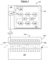
- a device 100 for probing an object 102 comprises an ultrasound probe 104 having a housing 106, that is to say a non-deformable structural element which serves as a reference attached to the probe 104, in which are arranged, for example linearly or matriciellement N transducers 108 1 , ..., 108 N fixed or mobile.
- the object 102 is, for example, a mechanical part that it is desired to examine by non-destructive testing or, in a medical context, a part of a human body that it is desired to control in a non-invasive manner.
- the object 102 is immersed in a liquid, such as water 110, and the probe 104 is kept at a distance from the object 102 so that the water 110 separates them.
- the probe 104 could be in direct contact with the object 102.
- the transducers 108 1 , ..., 108 N are designed to emit ultrasonic waves towards the object 102 in response to control signals identified under the general reference C, in principal directions parallel to each other, indicated by dashed arrows on the figure 1 , and in a main plane which is that of the figure.
- the transducers 108 1 , ..., 108 N are further designed to detect echoes of the ultrasonic waves reflected on and in the object 102 and to provide measurement signals identified under the general reference S and corresponding to these echoes.
- the transducers 108 1 ,..., 108 N fulfill both the transmission and reception functions, but different receivers of the transmitters could also be provided in different and independent boxes while remaining in conformity with the principles of the 'invention.
- the sounding device 100 further comprises an electronic circuit 112 for controlling the transducers 108 1 , ..., 108 N of the probe 104 and for processing the measurement signals S.
- This electronic circuit 112 is connected to the probe 104 in order to to transmit the control signals C to it and to receive the measurement signals S.
- the electronic circuit 112 is for example that of a computer. It presents a central processing unit 114, such as a microprocessor designed to transmit the control signals C to the probe 104 and to receive the measurement signals S from the probe 104, and a memory 116 in which a measurement program is recorded. computer 118.
- the set S of the LxN measurement signals thus transmitted by the transducers 108 1 , ..., 108 N is returned by the probe 104 to the central processing unit 114.
- the computer program 118 further comprises instructions 122 for constructing a matrix K (t) of ultrasonic temporal signals of size L ⁇ N, each coefficient K i, j (t) of this matrix representing the measurement signal received by the transducer 108. j in response to the i-th emission.
- the computer program 118 further comprises instructions 124 for temporal filtering of the matrix K (t), this filtering to remove any information at flight times excluded from the area of interest in the object 102.
- the computer program 118 further comprises instructions 126 for transforming the matrix K (t) into a matrix K ( ⁇ ) of frequency signals by Fourier transform, advantageously by discrete Fourier transform after temporal sampling of the coefficients of the matrix K (t), or, even more advantageously, by FFT (Fast Fourier Transform) if the number of samples of each coefficient of the matrix K (t) allows it.
- Fourier transform advantageously by discrete Fourier transform after temporal sampling of the coefficients of the matrix K (t), or, even more advantageously, by FFT (Fast Fourier Transform) if the number of samples of each coefficient of the matrix K (t) allows it.
- the computer program 118 further comprises instructions 128 for breaking down the matrix K ( ⁇ ) of frequency signals into singular values over a frequency band so as to diagonalize it.
- K ⁇ U . S .
- the computer program 118 further comprises instructions 130 for rearranging, as a function of frequency, the matrix K ( ⁇ ) into a matrix K ( ⁇ ) by a reorganization of the frequency components of its singular and vector values. singular.
- the same singular value of the matrix S can correspond to both the fault, the interface and the structure noise according to the frequencies considered in the spectral bandwidth of the probe.
- the computer program 118 further comprises instructions 132 for reducing the rank of the matrix K ( ⁇ ) (or that of the matrix K ( ⁇ ) if the optional instructions 130 are not executed), possibly reorganized, eliminating a part of the singular values ⁇ i .
- This elimination is done according to a criterion of distinction between singular values related to defects and singular values related to noise, the first being amplitudes higher than the seconds. Given the fact that ⁇ 1 ⁇ ... ⁇ ⁇ L ⁇ 0, it is necessary to find the value P between 1 and L such that ⁇ 1 , ..., ⁇ P can be considered as related to defects to detect in the object 102 and ⁇ P + 1 , ..., ⁇ L can be eliminated because considered as related to noise.
- the determination of P is done by studying the decay curve of the amplitudes of the singular values and more precisely by the study of their differences of successive amplitudes (ie ⁇ 2 - ⁇ 1 , ..., ⁇ N - ⁇ N-1 ) at a reference frequency, for example the center frequency of the frequency spectrum of the matrix K ( ⁇ ).
- P may be equal to the index associated with the singular value for which the curve of decay of the singular values exhibits a change of curvature, more precisely a slope break, which is indicative of a significant variation in the differences of successive amplitudes between singular values.
- Such a determination of P can be done in known manner in itself by linear regression on the assumption of a linear decay into two pieces.
- K ( ⁇ ) kf ⁇ + kb ⁇
- the matrix Kf ( ⁇ ) thus reconstituted is a denoised matrix of frequency signals, the noise subspace represented by the matrix Kb ( ⁇ ) having been eliminated.
- the computer program 118 further comprises instructions 134 for transforming the matrix Kf ( ⁇ ) into a denoised matrix Kf (t) of time signals by inverse Fourier transform, advantageously by inverse discrete Fourier transform, or even more advantageously again, by calculation of IFFT (Inverse Fast Fourier Transform) if the number of samples of each coefficient of the matrix Kf ( ⁇ ) allows it.
- IFFT Inverse Fast Fourier Transform
- the computer program 118 includes instructions 136 for achieving a synthetic focus in all points such as that defined in the aforementioned article of C. Holmes et al. On the denoised matrix Kf (t).
- a digital image of the area of interest whose quality is better is reconstructed if the synthetic focusing had been performed on the non-denoised matrix K (t).
- the SNR is improved.
- the processing unit 114 executing the instructions 120 controls the transmission and reception sequences of the transducers 108 1 ,..., 108 N for the acquisition of the matrix K (t).
- predetermined delay laws are applied to the transducers constituting the sub-opening of M transducers. They allow the focusing of the waves emitted at a point O situated at a depth of F mm below the probe 104. The emitted wavefront does not stop at the point O. A wave diverges from this point and propagates in the medium. For an observer located at a depth greater than F, everything happens as if the diverging wave came from a virtual source located in O. The created virtual source does not have a perfectly omnidirectional directivity like that of a point source but has an angular directivity of angle ⁇ wide enough.
- This directivity can be adjusted by modifying the delays applied to the transducers of the sub-opening so that the wave emitted by the virtual source is directed in a preferred direction in the object 102.
- the detection of defects in this object is thus improved. zoned.
- the figure 4 illustrates the principle of virtual sources according to two laws of delays provided by way of example.
- the processing unit 114 executing the instructions 122 constructs the matrix K (t), each coefficient K i, j (t) of this matrix representing the measurement signal received by the transducer 108 j. response to the i-th emission, this signal being digitized to facilitate its subsequent processing.
- the processing unit 114 executing the instructions 124 performs a temporal filtering of the matrix K (t), this filtering being intended to eliminate any information at flight times excluded from the zone d. 'interest.
- This step 206 is intended to facilitate then the separation of the two subspaces represented by the matrices Kf ( ⁇ ) and Kb ( ⁇ ), in particular when the defects to be imaged are close to a strongly echoic interface, such as a background of room. It makes it possible to limit the zone to be imaged to a neighborhood close to the defects by excluding in particular the disturbing echogenic interfaces. She finds all her interest in the imagery of cracks forming from the bottom of the object.
- the processing unit 114 executing the instructions 126 performs a discrete Fourier transform of the matrix K (t) to obtain the matrix K ( ⁇ ) of frequency signals.
- the processing unit 114 executing the instructions 128 diagonalizes the matrix K ( ⁇ ) by decomposing it into singular values, as detailed previously.
- the processing unit 114 executing the instructions 130 rearranges the matrix K ( ⁇ ) into a matrix K ( ⁇ ) by a reorganization of the frequency components of the singular values and singular vectors of the decomposition matrices S ( ⁇ ), U ( ⁇ ) and V ( ⁇ ) into new decomposition matrices S ( ⁇ ), U ( ⁇ ) and V ( ⁇ ).
- the reorganized matrix K ( ⁇ ) is now decomposed into singular values each presenting singular vectors optimizing their correlations at all frequencies, either with respect to a chosen constant reference frequency (first variant) or step by step (second variant ).
- first variant constant reference frequency
- second variant second variant
- a fault is associated with the same singular value for all the frequencies in the spectral band of the probe.
- An example of amplitude frequency distributions (A) of L eigenvalues is shown in FIG. figure 5 .
- the normalized amplitude decay of these eigenvalues, either on average in the frequency spectrum of the matrix K ( ⁇ ), or at a selected central frequency, is for example illustrated on FIG. figure 6 : in this example, there is a significant difference in amplitude between the first and second singular values.
- the processing unit 114 executing the instructions 134 performs a discrete inverse Fourier transform of the matrix Kf ( ⁇ ) to obtain the denoised matrix Kf (t) of time signals.
- FIG. 7 illustrates examples of reconstructed digital images, either directly after the step 204 of constructing the matrix K (t) for the figure 7 after all the steps 202 to 216 have been executed for the figure 8 .
- the computer program instructions could be replaced by electronic circuits dedicated to the functions performed during the execution of these instructions.
Landscapes
- Physics & Mathematics (AREA)
- Engineering & Computer Science (AREA)
- General Physics & Mathematics (AREA)
- Radar, Positioning & Navigation (AREA)
- Remote Sensing (AREA)
- General Health & Medical Sciences (AREA)
- Pathology (AREA)
- Health & Medical Sciences (AREA)
- Life Sciences & Earth Sciences (AREA)
- Chemical & Material Sciences (AREA)
- Analytical Chemistry (AREA)
- Biochemistry (AREA)
- Immunology (AREA)
- Acoustics & Sound (AREA)
- Signal Processing (AREA)
- Computer Networks & Wireless Communication (AREA)
- Mathematical Physics (AREA)
- Spectroscopy & Molecular Physics (AREA)
- Algebra (AREA)
- Mathematical Analysis (AREA)
- Mathematical Optimization (AREA)
- Pure & Applied Mathematics (AREA)
- Investigating Or Analyzing Materials By The Use Of Ultrasonic Waves (AREA)
- Ultra Sonic Daignosis Equipment (AREA)
Claims (11)
- Verfahren (200) zur Verarbeitung von Ultraschallsignalen (S), hervorgegangen aus einer Erfassung durch Echolotung, aufweisend die folgenden Schritte:- Steuern (202) einer Vielzahl von Sendetransducern (1081, ..., 108N) für L aufeinanderfolgende Sendungen von Ultraschallwellen in Richtung eines interessierenden Bereichs (102),- Steuern (202) von N Empfangstransducern (1081, ..., 108N) derart, dass gleichzeitig und während einer vorbestimmten Dauer für jede aufeinanderfolgende Sendung N Messsignale empfangen werden, die insbesondere Rauschechos messen, die Reflexionen der in dem interessierenden Bereich betrachteten Sendung geschuldet sind,- Erhalten (204) einer Matrix (K(t)) temporaler Ultraschallsignale der Größe LxN, wobei jeder Koeffizient Ki,j(t) dieser Matrix das von dem j-ten Empfangstransducer aufgrund der i-ten Sendung empfangene Messsignal repräsentiert,- Transformieren (208) der Matrix (K(t)) temporaler Signale in eine Matrix (K(ω)) von Frequenzsignalen,- Zerlegen der Matrix (K(ω)) von Frequenzsignalen in Einzelwerte (210),dadurch gekennzeichnet, dass es einen Rauschunterdrückungsschritt (208, 210, 212, 214, 216) der Matrix (K(t)) der temporalen Ultraschallsignale aufweist durch:- Entfernen (214) eines Teils der Einzelwerte und zugeordneten Einzelvektoren, hervorgegangen aus der Zerlegung in Einzelwerte (210), gemäß einem vorbestimmten Unterscheidungskriterium zwischen Einzelwerten, die mit Fehlern verbunden sind, und Einzelwerten, die mit Rauschen verbunden sind, wobei sich dieses Kriterium auf Differenzen aufeinanderfolgender Amplituden zwischen Einzelwerten in einer abnehmenden Amplitudenreihe der auf der Basis der Matrix (K(ω)) der Frequenzsignale bestimmten Einzelwerte bezieht,- Wiederherstellen (214) einer von Frequenzsignalen entrauschten Matrix (Kf(ω)) auf der Basis der nicht entfernten Einzelwerte und Einzelvektoren, und- inverses Transformieren (216) dieser von Frequenzsignalen entrauschten Matrix (Kf(ω)) in eine von temporalen Signalen entrauschte Matrix (Kf(t)).
- Verfahren (200) zur Verarbeitung von Ultraschallsignalen nach Anspruch 1, wobei das vorbestimmte Unterscheidungskriterium zwischen Einzelwerten, die mit Fehlern verbunden sind, und Einzelwerten, die mit Rauschen verbunden sind, ein Kurvenänderungskriterium in dieser abnehmenden Reihe der Einzelwertamplituden ist.
- Verfahren (200) zur Verarbeitung von Ultraschallsignalen nach Anspruch 1, wobei das vorbestimmte Unterscheidungskriterium zwischen Einzelwerten, die mit Fehlern verbunden sind, und Einzelwerten, die mit Rauschen verbunden sind, ein Neigungsunterbrechungskriterium, bestimmt durch lineare Regression auf der Hypothese einer linearen Abnahme in zwei Stücken in dieser abnehmenden Reihe der Einzelwertamplituden, ist.
- Verfahren (200) zur Verarbeitung von Ultraschallsignalen nach einem der Ansprüche 1 bis 3, wobei die Transformation (208) und die inverse Transformation (216) diskrete Fourier-Transformationen sind.
- Verfahren (200) zur Verarbeitung von Ultraschallsignalen nach einem der Ansprüche 1 bis 4, aufweisend, vor dem Rauschunterdrückungsschritt (208, 210, 212, 214, 216), einen Schritt des Filterns (206) der Matrix (K(t)) der temporalen Signale durch Unterdrückung aller Informationen, die sich in Flugzeiten befinden, die aus dem interessierenden Bereich (102) ausgeschlossen sind.
- Verfahren (200) zur Verarbeitung von Ultraschallsignalen nach einem der Ansprüche 1 bis 5, aufweisend einen Reorganisationsschritt (212) von Frequenzbestandteilen der Einzelwerte und Einzelvektoren der Matrix (K(ω)) der Frequenzsignale auf der Basis einer Optimierung von Korrelationen zwischen Auftrittshäufigkeiten der Einzelvektoren derart, dass eine Übereinstimmung zwischen Einzelwerten und Fehlern in dem interessierenden Bereich (102) optimiert und damit die Filterung des Rauschens optimiert wird.
- Verfahren (200) zur Verarbeitung von Ultraschallsignalen nach einem der Ansprüche 1 bis 6, wobei, bei jeder aufeinanderfolgenden Sendung, M benachbarte Sendetransducer beansprucht werden und ein Verzögerungsgesetz auf diese M Sendetransducer derart angewendet wird, dass eine sphärische Welle, hervorgegangen aus einer virtuellen Quelle (O), die sich in einem vorbestimmten Abstand (F) von der Vielzahl von Sendetransducern (1081, ..., 108N) befindet, gesendet wird.
- Verfahren (200) zur Verarbeitung von Ultraschallsignalen nach einem der Ansprüche 1 bis 7, wobei jeder Empfang von L' virtuellen Empfangstransducern durchgeführt wird, wobei jeder virtuelle Empfangstransducer von M' benachbarten Empfangstransducern gebildet ist, auf welche ein Verzögerungsgesetz angewendet wird.
- Verfahren (200) zur Verarbeitung von Ultraschallsignalen nach einem der Ansprüche 1 bis 8, aufweisend einen zusätzlichen Wiederherstellungsschritt (218) eines digitalen Bildes des interessierenden Bereichs (102) auf der Basis der von temporalen Signalen entrauschten Matrix (Kf(t)), insbesondere durch eine Verarbeitung vom Typ synthetische Total-Fokussierung.
- Rechnerprogramm (118), herunterladbar von einem Kommunikationsnetz und/oder aufgezeichnet auf einem rechnerlesbaren Träger und/oder ausführbar von einem Prozessor (114), dadurch gekennzeichnet, dass es Befehle für die Ausführung der Schritte eines Verfahrens (200) zur Verarbeitung von Ultraschallsignalen nach einem der Ansprüche 1 bis 9 umfasst, wenn das Programm auf einem Rechner (112) ausgeführt wird.
- Echolotungsvorrichtung (100), aufweisend:- eine Sonde (104), umfassend eine Vielzahl von Ultraschall-Sendetransducern (1081, ..., 108N) und eine Vielzahl von Ultraschall-Empfangstransducern (1081, ..., 108N), und- Steuer- und Verarbeitungsmittel (112) der Transducer, die für die Durchführung eines Verfahrens (200) zur Verarbeitung von Ultraschallsignalen nach einem der Ansprüche 1 bis 9 ausgebildet sind.
Applications Claiming Priority (2)
| Application Number | Priority Date | Filing Date | Title |
|---|---|---|---|
| FR1256718A FR2993362B1 (fr) | 2012-07-12 | 2012-07-12 | Procede de traitement de signaux issus d'une acquisition par sondage ultrasonore, programme d'ordinateur et dispositif de sondage a ultrasons correspondants |
| PCT/FR2013/051677 WO2014009671A1 (fr) | 2012-07-12 | 2013-07-12 | Procédé de traitement de signaux issus d'une acquisition par sondage ultrasonore, programme d'ordinateur et dispositif de sondage à ultrasons correspondants |
Publications (2)
| Publication Number | Publication Date |
|---|---|
| EP2872884A1 EP2872884A1 (de) | 2015-05-20 |
| EP2872884B1 true EP2872884B1 (de) | 2018-09-26 |
Family
ID=47191879
Family Applications (1)
| Application Number | Title | Priority Date | Filing Date |
|---|---|---|---|
| EP13747440.9A Not-in-force EP2872884B1 (de) | 2012-07-12 | 2013-07-12 | Verfahren zur verarbeitung von ultraschalltestdaten, computerprogramm und entsprechende ultraschalltestvorrichtung |
Country Status (7)
| Country | Link |
|---|---|
| US (1) | US9903842B2 (de) |
| EP (1) | EP2872884B1 (de) |
| JP (1) | JP6258314B2 (de) |
| CA (1) | CA2878545C (de) |
| ES (1) | ES2703326T3 (de) |
| FR (1) | FR2993362B1 (de) |
| WO (1) | WO2014009671A1 (de) |
Families Citing this family (19)
| Publication number | Priority date | Publication date | Assignee | Title |
|---|---|---|---|---|
| CN103743810B (zh) * | 2013-12-24 | 2016-05-25 | 华中科技大学 | 一种磁致伸缩导波检测信号处理方法及装置 |
| FR3036192B1 (fr) | 2015-05-12 | 2017-06-16 | Electricite De France | Procede et dispositif de sondage par propagation d'ondes |
| US10126272B2 (en) * | 2015-12-29 | 2018-11-13 | General Electric Company | Systems and methods for ultrasonic inspection of turbine components |
| CN106290587B (zh) * | 2016-08-22 | 2019-07-12 | 中国石油化工股份有限公司 | 基于svd分解的储罐底板超声导波检测信号降噪算法 |
| FR3060768B1 (fr) | 2016-12-15 | 2019-05-24 | Commissariat A L'energie Atomique Et Aux Energies Alternatives | Procede d'acquisition de signaux par sondage ultrasonore, programme d'ordinateur et dispositif de sondage a ultrasons correspondants |
| FR3060753B1 (fr) * | 2016-12-15 | 2019-07-26 | Commissariat A L'energie Atomique Et Aux Energies Alternatives | Procede de traitement de signaux issus d'une acquisition par sondage ultrasonore, programme d'ordinateur et dispositif de sondage a ultrasons correspondants |
| CN108645920B (zh) * | 2018-04-09 | 2020-12-22 | 华南理工大学 | 一种基于去噪和对齐的钢轨超声探伤的直达波抑制方法 |
| FR3080453B1 (fr) * | 2018-04-23 | 2020-05-01 | Safran | Procede et systeme de controle non destructif d'une piece mecanique |
| FR3085481B1 (fr) * | 2018-09-03 | 2020-11-27 | Electricite De France | Procede de detection et de caracterisation par ultrasons de defauts dans un materiau heterogene |
| CN110274957B (zh) * | 2019-07-19 | 2021-01-29 | 西安交通大学 | 一种大阻尼层合结构界面粘接质量检测方法 |
| CN111444963B (zh) * | 2020-03-27 | 2023-08-25 | 中南大学 | 一种基于ssa-svr模型的高炉铁水硅含量预测方法 |
| CN111307945B (zh) * | 2020-04-09 | 2023-07-21 | 上海工程技术大学 | 一种基于超声阵列检测无砟轨道近表面缺陷的成像方法及装置 |
| WO2022006735A1 (zh) * | 2020-07-07 | 2022-01-13 | 深圳迈瑞生物医疗电子股份有限公司 | 超声造影成像方法、超声成像装置和存储介质 |
| FR3118179B1 (fr) * | 2020-12-17 | 2025-07-04 | Electricite De France | procédé, dispositif et programme de détection par ultrasons de défauts dans un matériau |
| CN112861731B (zh) * | 2021-02-09 | 2023-04-18 | 西安科技大学 | 一种基于参数寻优的超声信号去噪方法 |
| CN113176346B (zh) * | 2021-04-27 | 2022-09-23 | 汕头市超声检测科技有限公司 | 一种基于曲线的全聚焦超声实时成像方法 |
| CN113533526B (zh) * | 2021-06-02 | 2022-10-11 | 中北大学 | 超声相控阵界面脱粘缺陷全聚焦c扫描成像方法及系统 |
| CN114324598B (zh) * | 2021-12-03 | 2023-05-26 | 江西昌河航空工业有限公司 | 一种螺栓超声检测的高质量成像方法及系统 |
| CN116482231A (zh) * | 2023-04-12 | 2023-07-25 | 中国工程物理研究院化工材料研究所 | 一种材料内部缺陷高信噪比超声成像方法 |
Family Cites Families (7)
| Publication number | Priority date | Publication date | Assignee | Title |
|---|---|---|---|---|
| JP2000316852A (ja) * | 1999-05-06 | 2000-11-21 | Sekisui Chem Co Ltd | 骨粗鬆症診断装置及び骨粗鬆症診断方法 |
| FR2849368A1 (fr) * | 2002-12-30 | 2004-07-02 | Koninkl Philips Electronics Nv | Detection de defauts de petite taille en imagerie ultrasonore medicale |
| US20050154306A1 (en) * | 2004-01-14 | 2005-07-14 | Michael Burcher | Dort process-based method and system for adaptive beamforming in estimating the aberration in a medium |
| FR2932339B1 (fr) * | 2008-06-09 | 2012-11-23 | Centre Nat Rech Scient | Procede et dispositif de sondage par propagation d'ondes |
| JP5539218B2 (ja) * | 2008-11-10 | 2014-07-02 | キヤノン株式会社 | 超音波診断システムおよび超音波診断装置 |
| FR2946753B1 (fr) * | 2009-06-11 | 2011-07-22 | Centre Nat Rech Scient | Procede et dispositif ultrasonores pour caracteriser un milieu |
| FR2963443B1 (fr) * | 2010-07-28 | 2012-08-17 | Commissariat Energie Atomique | Procede de commande de transducteurs d'une sonde a ultrasons, programme d'ordinateur correspondant et dispositif de sondage a ultrasons |
-
2012
- 2012-07-12 FR FR1256718A patent/FR2993362B1/fr not_active Expired - Fee Related
-
2013
- 2013-07-12 ES ES13747440T patent/ES2703326T3/es active Active
- 2013-07-12 JP JP2015521053A patent/JP6258314B2/ja not_active Expired - Fee Related
- 2013-07-12 CA CA2878545A patent/CA2878545C/fr not_active Expired - Fee Related
- 2013-07-12 EP EP13747440.9A patent/EP2872884B1/de not_active Not-in-force
- 2013-07-12 WO PCT/FR2013/051677 patent/WO2014009671A1/fr not_active Ceased
- 2013-07-12 US US14/414,263 patent/US9903842B2/en not_active Expired - Fee Related
Non-Patent Citations (1)
| Title |
|---|
| None * |
Also Published As
| Publication number | Publication date |
|---|---|
| WO2014009671A1 (fr) | 2014-01-16 |
| FR2993362A1 (fr) | 2014-01-17 |
| US20150212051A1 (en) | 2015-07-30 |
| CA2878545C (fr) | 2021-07-20 |
| JP2015522175A (ja) | 2015-08-03 |
| FR2993362B1 (fr) | 2016-07-01 |
| US9903842B2 (en) | 2018-02-27 |
| JP6258314B2 (ja) | 2018-01-10 |
| ES2703326T3 (es) | 2019-03-08 |
| EP2872884A1 (de) | 2015-05-20 |
| CA2878545A1 (fr) | 2014-01-16 |
Similar Documents
| Publication | Publication Date | Title |
|---|---|---|
| EP2872884B1 (de) | Verfahren zur verarbeitung von ultraschalltestdaten, computerprogramm und entsprechende ultraschalltestvorrichtung | |
| EP2294452B1 (de) | Messverfahren und -Vorrichtung unter Verwendung von Wellenausbreitung | |
| EP3824280B1 (de) | Verfahren und systeme zur nichtinvasiven charakterisierung eines heterogenen mediums mittels ultraschall | |
| FR3060753B1 (fr) | Procede de traitement de signaux issus d'une acquisition par sondage ultrasonore, programme d'ordinateur et dispositif de sondage a ultrasons correspondants | |
| EP0751743A1 (de) | Verfahren und gerät zur auswertung und charakterisierung von knocheneigenschaften | |
| FR2971342A1 (fr) | Dispositif d'imagerie avec optimisation de cadence | |
| EP3555659B1 (de) | Verfahren zur erfassung von ultraschallprüfsignalen sowie entsprechendes computerprogramm und ultraschallprüfvorrichtung | |
| WO2015092250A1 (fr) | Procédé de traitement de signaux issus d'une acquisition par sondage ultrasonore, programme d'ordinateur et dispositif de sondage à ultrasons correspondants | |
| WO2020128344A1 (fr) | Procédé d'imagerie ultrasonore par transformée de fourier bidimensionnelle, programme d'ordinateur et dispositif de sondage à ultrasons correspondants | |
| EP3295212B1 (de) | Verfahren und vorrichtung für sondierung mittels wellenausbreitung | |
| FR3065079B1 (fr) | Procede et dispositif de sondage ultrasonore pour l'obtention de courbes de dispersion d'un milieu sonde | |
| FR3140439A1 (fr) | Procédé d’imagerie ultrasonore par transformée de Fourier multidimensionnelle à l’aide de deux transducteurs multiéléments distincts | |
| EP4574056A1 (de) | Verfahren zur charakterisierung eines zielobjekts in einem medium | |
| EP2929343B1 (de) | Vorrichtung und verfahren zur ultraschalllbildgebeung mit filterung von artefakten aufgrund von interferenzen zwischen rekonstruktionsmoden | |
| CA3046106C (fr) | Procede de traitement de signaux issus d'une acquisition par sondage ultrasonore, programme d'ordinateur et dispositif de sondage a ultrasons correspondants | |
| FR3085096A1 (fr) | Procede et dispositif d'imagerie ameliore pour imager un objet | |
| WO2004104632A1 (fr) | Procede pour l'exploration et l'analyse d'une structure volumique |
Legal Events
| Date | Code | Title | Description |
|---|---|---|---|
| PUAI | Public reference made under article 153(3) epc to a published international application that has entered the european phase |
Free format text: ORIGINAL CODE: 0009012 |
|
| 17P | Request for examination filed |
Effective date: 20141229 |
|
| AK | Designated contracting states |
Kind code of ref document: A1 Designated state(s): AL AT BE BG CH CY CZ DE DK EE ES FI FR GB GR HR HU IE IS IT LI LT LU LV MC MK MT NL NO PL PT RO RS SE SI SK SM TR |
|
| AX | Request for extension of the european patent |
Extension state: BA ME |
|
| RIN1 | Information on inventor provided before grant (corrected) |
Inventor name: CASULA, OLIVIER Inventor name: BANNOUF, SOUAD Inventor name: PRADA JULIA, CLAIRE Inventor name: ROBERT, SEBASTIEN |
|
| DAX | Request for extension of the european patent (deleted) | ||
| GRAP | Despatch of communication of intention to grant a patent |
Free format text: ORIGINAL CODE: EPIDOSNIGR1 |
|
| STAA | Information on the status of an ep patent application or granted ep patent |
Free format text: STATUS: GRANT OF PATENT IS INTENDED |
|
| INTG | Intention to grant announced |
Effective date: 20180507 |
|
| GRAS | Grant fee paid |
Free format text: ORIGINAL CODE: EPIDOSNIGR3 |
|
| GRAA | (expected) grant |
Free format text: ORIGINAL CODE: 0009210 |
|
| STAA | Information on the status of an ep patent application or granted ep patent |
Free format text: STATUS: THE PATENT HAS BEEN GRANTED |
|
| AK | Designated contracting states |
Kind code of ref document: B1 Designated state(s): AL AT BE BG CH CY CZ DE DK EE ES FI FR GB GR HR HU IE IS IT LI LT LU LV MC MK MT NL NO PL PT RO RS SE SI SK SM TR |
|
| REG | Reference to a national code |
Ref country code: GB Ref legal event code: FG4D Free format text: NOT ENGLISH |
|
| REG | Reference to a national code |
Ref country code: CH Ref legal event code: EP |
|
| REG | Reference to a national code |
Ref country code: AT Ref legal event code: REF Ref document number: 1046617 Country of ref document: AT Kind code of ref document: T Effective date: 20181015 |
|
| REG | Reference to a national code |
Ref country code: IE Ref legal event code: FG4D Free format text: LANGUAGE OF EP DOCUMENT: FRENCH |
|
| REG | Reference to a national code |
Ref country code: DE Ref legal event code: R096 Ref document number: 602013044195 Country of ref document: DE |
|
| REG | Reference to a national code |
Ref country code: NL Ref legal event code: MP Effective date: 20180926 |
|
| PG25 | Lapsed in a contracting state [announced via postgrant information from national office to epo] |
Ref country code: RS Free format text: LAPSE BECAUSE OF FAILURE TO SUBMIT A TRANSLATION OF THE DESCRIPTION OR TO PAY THE FEE WITHIN THE PRESCRIBED TIME-LIMIT Effective date: 20180926 Ref country code: LT Free format text: LAPSE BECAUSE OF FAILURE TO SUBMIT A TRANSLATION OF THE DESCRIPTION OR TO PAY THE FEE WITHIN THE PRESCRIBED TIME-LIMIT Effective date: 20180926 Ref country code: BG Free format text: LAPSE BECAUSE OF FAILURE TO SUBMIT A TRANSLATION OF THE DESCRIPTION OR TO PAY THE FEE WITHIN THE PRESCRIBED TIME-LIMIT Effective date: 20181226 Ref country code: SE Free format text: LAPSE BECAUSE OF FAILURE TO SUBMIT A TRANSLATION OF THE DESCRIPTION OR TO PAY THE FEE WITHIN THE PRESCRIBED TIME-LIMIT Effective date: 20180926 Ref country code: FI Free format text: LAPSE BECAUSE OF FAILURE TO SUBMIT A TRANSLATION OF THE DESCRIPTION OR TO PAY THE FEE WITHIN THE PRESCRIBED TIME-LIMIT Effective date: 20180926 Ref country code: GR Free format text: LAPSE BECAUSE OF FAILURE TO SUBMIT A TRANSLATION OF THE DESCRIPTION OR TO PAY THE FEE WITHIN THE PRESCRIBED TIME-LIMIT Effective date: 20181227 Ref country code: NO Free format text: LAPSE BECAUSE OF FAILURE TO SUBMIT A TRANSLATION OF THE DESCRIPTION OR TO PAY THE FEE WITHIN THE PRESCRIBED TIME-LIMIT Effective date: 20181226 |
|
| REG | Reference to a national code |
Ref country code: LT Ref legal event code: MG4D |
|
| PG25 | Lapsed in a contracting state [announced via postgrant information from national office to epo] |
Ref country code: HR Free format text: LAPSE BECAUSE OF FAILURE TO SUBMIT A TRANSLATION OF THE DESCRIPTION OR TO PAY THE FEE WITHIN THE PRESCRIBED TIME-LIMIT Effective date: 20180926 Ref country code: AL Free format text: LAPSE BECAUSE OF FAILURE TO SUBMIT A TRANSLATION OF THE DESCRIPTION OR TO PAY THE FEE WITHIN THE PRESCRIBED TIME-LIMIT Effective date: 20180926 Ref country code: LV Free format text: LAPSE BECAUSE OF FAILURE TO SUBMIT A TRANSLATION OF THE DESCRIPTION OR TO PAY THE FEE WITHIN THE PRESCRIBED TIME-LIMIT Effective date: 20180926 |
|
| REG | Reference to a national code |
Ref country code: ES Ref legal event code: FG2A Ref document number: 2703326 Country of ref document: ES Kind code of ref document: T3 Effective date: 20190308 |
|
| REG | Reference to a national code |
Ref country code: AT Ref legal event code: MK05 Ref document number: 1046617 Country of ref document: AT Kind code of ref document: T Effective date: 20180926 |
|
| PG25 | Lapsed in a contracting state [announced via postgrant information from national office to epo] |
Ref country code: IS Free format text: LAPSE BECAUSE OF FAILURE TO SUBMIT A TRANSLATION OF THE DESCRIPTION OR TO PAY THE FEE WITHIN THE PRESCRIBED TIME-LIMIT Effective date: 20190126 Ref country code: NL Free format text: LAPSE BECAUSE OF FAILURE TO SUBMIT A TRANSLATION OF THE DESCRIPTION OR TO PAY THE FEE WITHIN THE PRESCRIBED TIME-LIMIT Effective date: 20180926 Ref country code: EE Free format text: LAPSE BECAUSE OF FAILURE TO SUBMIT A TRANSLATION OF THE DESCRIPTION OR TO PAY THE FEE WITHIN THE PRESCRIBED TIME-LIMIT Effective date: 20180926 Ref country code: AT Free format text: LAPSE BECAUSE OF FAILURE TO SUBMIT A TRANSLATION OF THE DESCRIPTION OR TO PAY THE FEE WITHIN THE PRESCRIBED TIME-LIMIT Effective date: 20180926 Ref country code: IT Free format text: LAPSE BECAUSE OF FAILURE TO SUBMIT A TRANSLATION OF THE DESCRIPTION OR TO PAY THE FEE WITHIN THE PRESCRIBED TIME-LIMIT Effective date: 20180926 Ref country code: RO Free format text: LAPSE BECAUSE OF FAILURE TO SUBMIT A TRANSLATION OF THE DESCRIPTION OR TO PAY THE FEE WITHIN THE PRESCRIBED TIME-LIMIT Effective date: 20180926 Ref country code: CZ Free format text: LAPSE BECAUSE OF FAILURE TO SUBMIT A TRANSLATION OF THE DESCRIPTION OR TO PAY THE FEE WITHIN THE PRESCRIBED TIME-LIMIT Effective date: 20180926 Ref country code: PL Free format text: LAPSE BECAUSE OF FAILURE TO SUBMIT A TRANSLATION OF THE DESCRIPTION OR TO PAY THE FEE WITHIN THE PRESCRIBED TIME-LIMIT Effective date: 20180926 |
|
| PG25 | Lapsed in a contracting state [announced via postgrant information from national office to epo] |
Ref country code: SM Free format text: LAPSE BECAUSE OF FAILURE TO SUBMIT A TRANSLATION OF THE DESCRIPTION OR TO PAY THE FEE WITHIN THE PRESCRIBED TIME-LIMIT Effective date: 20180926 Ref country code: SK Free format text: LAPSE BECAUSE OF FAILURE TO SUBMIT A TRANSLATION OF THE DESCRIPTION OR TO PAY THE FEE WITHIN THE PRESCRIBED TIME-LIMIT Effective date: 20180926 Ref country code: PT Free format text: LAPSE BECAUSE OF FAILURE TO SUBMIT A TRANSLATION OF THE DESCRIPTION OR TO PAY THE FEE WITHIN THE PRESCRIBED TIME-LIMIT Effective date: 20190126 |
|
| REG | Reference to a national code |
Ref country code: DE Ref legal event code: R097 Ref document number: 602013044195 Country of ref document: DE |
|
| PG25 | Lapsed in a contracting state [announced via postgrant information from national office to epo] |
Ref country code: DK Free format text: LAPSE BECAUSE OF FAILURE TO SUBMIT A TRANSLATION OF THE DESCRIPTION OR TO PAY THE FEE WITHIN THE PRESCRIBED TIME-LIMIT Effective date: 20180926 |
|
| PLBE | No opposition filed within time limit |
Free format text: ORIGINAL CODE: 0009261 |
|
| STAA | Information on the status of an ep patent application or granted ep patent |
Free format text: STATUS: NO OPPOSITION FILED WITHIN TIME LIMIT |
|
| 26N | No opposition filed |
Effective date: 20190627 |
|
| PG25 | Lapsed in a contracting state [announced via postgrant information from national office to epo] |
Ref country code: SI Free format text: LAPSE BECAUSE OF FAILURE TO SUBMIT A TRANSLATION OF THE DESCRIPTION OR TO PAY THE FEE WITHIN THE PRESCRIBED TIME-LIMIT Effective date: 20180926 |
|
| PG25 | Lapsed in a contracting state [announced via postgrant information from national office to epo] |
Ref country code: MC Free format text: LAPSE BECAUSE OF FAILURE TO SUBMIT A TRANSLATION OF THE DESCRIPTION OR TO PAY THE FEE WITHIN THE PRESCRIBED TIME-LIMIT Effective date: 20180926 |
|
| REG | Reference to a national code |
Ref country code: CH Ref legal event code: PL |
|
| PG25 | Lapsed in a contracting state [announced via postgrant information from national office to epo] |
Ref country code: TR Free format text: LAPSE BECAUSE OF FAILURE TO SUBMIT A TRANSLATION OF THE DESCRIPTION OR TO PAY THE FEE WITHIN THE PRESCRIBED TIME-LIMIT Effective date: 20180926 |
|
| REG | Reference to a national code |
Ref country code: BE Ref legal event code: MM Effective date: 20190731 |
|
| PG25 | Lapsed in a contracting state [announced via postgrant information from national office to epo] |
Ref country code: LI Free format text: LAPSE BECAUSE OF NON-PAYMENT OF DUE FEES Effective date: 20190731 Ref country code: CH Free format text: LAPSE BECAUSE OF NON-PAYMENT OF DUE FEES Effective date: 20190731 Ref country code: BE Free format text: LAPSE BECAUSE OF NON-PAYMENT OF DUE FEES Effective date: 20190731 Ref country code: LU Free format text: LAPSE BECAUSE OF NON-PAYMENT OF DUE FEES Effective date: 20190712 |
|
| PG25 | Lapsed in a contracting state [announced via postgrant information from national office to epo] |
Ref country code: IE Free format text: LAPSE BECAUSE OF NON-PAYMENT OF DUE FEES Effective date: 20190712 |
|
| PG25 | Lapsed in a contracting state [announced via postgrant information from national office to epo] |
Ref country code: CY Free format text: LAPSE BECAUSE OF FAILURE TO SUBMIT A TRANSLATION OF THE DESCRIPTION OR TO PAY THE FEE WITHIN THE PRESCRIBED TIME-LIMIT Effective date: 20180926 |
|
| PG25 | Lapsed in a contracting state [announced via postgrant information from national office to epo] |
Ref country code: MT Free format text: LAPSE BECAUSE OF FAILURE TO SUBMIT A TRANSLATION OF THE DESCRIPTION OR TO PAY THE FEE WITHIN THE PRESCRIBED TIME-LIMIT Effective date: 20180926 Ref country code: HU Free format text: LAPSE BECAUSE OF FAILURE TO SUBMIT A TRANSLATION OF THE DESCRIPTION OR TO PAY THE FEE WITHIN THE PRESCRIBED TIME-LIMIT; INVALID AB INITIO Effective date: 20130712 |
|
| PGFP | Annual fee paid to national office [announced via postgrant information from national office to epo] |
Ref country code: FR Payment date: 20210708 Year of fee payment: 9 |
|
| PGFP | Annual fee paid to national office [announced via postgrant information from national office to epo] |
Ref country code: DE Payment date: 20210721 Year of fee payment: 9 Ref country code: ES Payment date: 20210819 Year of fee payment: 9 Ref country code: GB Payment date: 20210722 Year of fee payment: 9 |
|
| PG25 | Lapsed in a contracting state [announced via postgrant information from national office to epo] |
Ref country code: MK Free format text: LAPSE BECAUSE OF FAILURE TO SUBMIT A TRANSLATION OF THE DESCRIPTION OR TO PAY THE FEE WITHIN THE PRESCRIBED TIME-LIMIT Effective date: 20180926 |
|
| REG | Reference to a national code |
Ref country code: DE Ref legal event code: R119 Ref document number: 602013044195 Country of ref document: DE |
|
| GBPC | Gb: european patent ceased through non-payment of renewal fee |
Effective date: 20220712 |
|
| PG25 | Lapsed in a contracting state [announced via postgrant information from national office to epo] |
Ref country code: FR Free format text: LAPSE BECAUSE OF NON-PAYMENT OF DUE FEES Effective date: 20220731 |
|
| PG25 | Lapsed in a contracting state [announced via postgrant information from national office to epo] |
Ref country code: GB Free format text: LAPSE BECAUSE OF NON-PAYMENT OF DUE FEES Effective date: 20220712 Ref country code: DE Free format text: LAPSE BECAUSE OF NON-PAYMENT OF DUE FEES Effective date: 20230201 |
|
| REG | Reference to a national code |
Ref country code: ES Ref legal event code: FD2A Effective date: 20230830 |
|
| PG25 | Lapsed in a contracting state [announced via postgrant information from national office to epo] |
Ref country code: ES Free format text: LAPSE BECAUSE OF NON-PAYMENT OF DUE FEES Effective date: 20220713 |