EP2872905B1 - Kapazitiver körpernäherungssensorsystem - Google Patents
Kapazitiver körpernäherungssensorsystem Download PDFInfo
- Publication number
- EP2872905B1 EP2872905B1 EP13817134.3A EP13817134A EP2872905B1 EP 2872905 B1 EP2872905 B1 EP 2872905B1 EP 13817134 A EP13817134 A EP 13817134A EP 2872905 B1 EP2872905 B1 EP 2872905B1
- Authority
- EP
- European Patent Office
- Prior art keywords
- capacitance
- sensor
- perimeter
- human body
- area
- Prior art date
- Legal status (The legal status is an assumption and is not a legal conclusion. Google has not performed a legal analysis and makes no representation as to the accuracy of the status listed.)
- Active
Links
Images


Classifications
-
- H—ELECTRICITY
- H03—ELECTRONIC CIRCUITRY
- H03K—PULSE TECHNIQUE
- H03K17/00—Electronic switching or gating, i.e. not by contact-making and –breaking
- H03K17/94—Electronic switching or gating, i.e. not by contact-making and –breaking characterised by the way in which the control signals are generated
- H03K17/945—Proximity switches
- H03K17/955—Proximity switches using a capacitive detector
-
- H—ELECTRICITY
- H04—ELECTRIC COMMUNICATION TECHNIQUE
- H04B—TRANSMISSION
- H04B1/00—Details of transmission systems, not covered by a single one of groups H04B3/00 - H04B13/00; Details of transmission systems not characterised by the medium used for transmission
- H04B1/38—Transceivers, i.e. devices in which transmitter and receiver form a structural unit and in which at least one part is used for functions of transmitting and receiving
- H04B1/3827—Portable transceivers
- H04B1/3833—Hand-held transceivers
- H04B1/3838—Arrangements for reducing RF exposure to the user, e.g. by changing the shape of the transceiver while in use
-
- H—ELECTRICITY
- H03—ELECTRONIC CIRCUITRY
- H03K—PULSE TECHNIQUE
- H03K2217/00—Indexing scheme related to electronic switching or gating, i.e. not by contact-making or -breaking covered by H03K17/00
- H03K2217/94—Indexing scheme related to electronic switching or gating, i.e. not by contact-making or -breaking covered by H03K17/00 characterised by the way in which the control signal is generated
- H03K2217/96—Touch switches
- H03K2217/9607—Capacitive touch switches
- H03K2217/960705—Safety of capacitive touch and proximity switches, e.g. increasing reliability, fail-safe
-
- H—ELECTRICITY
- H03—ELECTRONIC CIRCUITRY
- H03K—PULSE TECHNIQUE
- H03K2217/00—Indexing scheme related to electronic switching or gating, i.e. not by contact-making or -breaking covered by H03K17/00
- H03K2217/94—Indexing scheme related to electronic switching or gating, i.e. not by contact-making or -breaking covered by H03K17/00 characterised by the way in which the control signal is generated
- H03K2217/96—Touch switches
- H03K2217/9607—Capacitive touch switches
- H03K2217/96071—Capacitive touch switches characterised by the detection principle
- H03K2217/96073—Amplitude comparison
-
- H—ELECTRICITY
- H03—ELECTRONIC CIRCUITRY
- H03K—PULSE TECHNIQUE
- H03K2217/00—Indexing scheme related to electronic switching or gating, i.e. not by contact-making or -breaking covered by H03K17/00
- H03K2217/94—Indexing scheme related to electronic switching or gating, i.e. not by contact-making or -breaking covered by H03K17/00 characterised by the way in which the control signal is generated
- H03K2217/96—Touch switches
- H03K2217/9607—Capacitive touch switches
- H03K2217/960735—Capacitive touch switches characterised by circuit details
- H03K2217/960745—Capacitive differential; e.g. comparison with reference capacitance
-
- H—ELECTRICITY
- H04—ELECTRIC COMMUNICATION TECHNIQUE
- H04M—TELEPHONIC COMMUNICATION
- H04M2250/00—Details of telephonic subscriber devices
- H04M2250/12—Details of telephonic subscriber devices including a sensor for measuring a physical value, e.g. temperature or motion
Definitions
- This disclosure generally relates generally to a body proximity sensor, and more specifically to a body proximity sensor that employs capacitive sensors of different sizes and/or configurations to facilitate the determination of whether an object in proximity to an electronic device is a human body or a non-human object.
- RF radio-frequency
- EMF electromagnetic field
- Examples of such electronic devices include mobile communication devices, tablet computing devices, laptop computing devices, and the like. Human exposure to these RF EMF emissions is harmful if the radiation power is high, at close range, and/or over a prolonged time.
- DE 10 2007 048402 A1 discloses a system comprising a first sensor and a second sensor, each detecting a respective capacitance related to an object. The shapes of the sensors can be different. An electronic component is used to determine whether the interface system is correctly operated with an object or finger or incorrectly operated.
- US 2010/317302 A1 discloses a system and controller to adjust power of an RF signal source based on a detected parameter.
- a system that can be used as a body proximity sensor.
- the system includes a first sensor and a second sensor.
- the first sensor has a first shape and detects a first capacitance related to an object.
- the second sensor has a second shape different from the first shape and detects a second capacitance related to the object, wherein the first and second sensors are surrounded by a shield coupled to an active bias driver.
- the system also includes an electronic component that processes the first capacitance and the second capacitance to facilitate discrimination of whether the object is a human body or a non-human object.
- the system also includes a radiation source adapted to modify an emission of radiation in response to determining that the object is a human body.
- the embodiment of the system is as described in independent claim 1.
- a method in another non-limiting embodiment, can be used to determine whether an object is a human body or a non-human object.
- the method includes processing a first capacitance from a first sensor with a first shape and a second capacitance from a second sensor with a second shape different from the first sensor.
- the method also includes determining a type of object in proximity of the first sensor and the second sensor based on the first capacitance and the second capacitance.
- the first and second sensors are surrounded by a shield coupled to an active bias driver.
- the method also includes a radiation source adapted to modify an emission of radiation in response to determining that the object is a human body.
- the embodiment of the method is as described in independent claim 11.
- an apparatus in a further non-limiting example, can be used as a body proximity sensor.
- the apparatus includes a first sensor and a second sensor.
- the first sensor has a first shape and detects a first capacitance.
- the second sensor has a second shape different from the first shape and detects a second capacitance.
- the apparatus also includes an electronic component that processes the first capacitance and the second capacitance to facilitate determination of whether the object is a human body or a non-human object.
- Described herein are systems, apparatuses and methods that can facilitate detection of an object within the proximity of an electronic device and differentiate between a human body and a non-human object.
- the detection and differentiation are facilitated by a first capacitive sensor of a first shape and a second capacitive sensor of a second shape.
- the detection and determination can be made based on a comparison between a first capacitance from the first sensor and a second capacitance from the second sensor.
- RF EMF emissions of the electronic device can be reduced.
- FIG. 1 A schematic illustration of an example body detection system 100, according to an embodiment of the subject disclosure, is shown in FIG. 1 .
- the body detection system 100 can, for example, be miniaturized and included in an electronic device or apparatus, such as a mobile communications device, a tablet computing device, a laptop computing device, or other portable electronic device, to facilitate reduction in RF EMF emissions when a human body is in proximity to the electronic device.
- the system 100 can be included in the electronic device at a low cost.
- the body detection system 100 includes a first sensor (sensor 1) 108 and a second sensor (sensor 2) 110. It will be understood that the system 100 can include any number of sensors greater than or equal to 2. Two sensors 108, 110 are shown merely for simplicity of illustration and description.
- the sensors 108, 110 are located near to each other, as shown, for example, in FIGs. 2-5 .
- the sensors 108, 110 are of different shapes (in other words, the first sensor 108 has a first shape and the second sensor 110 has a second shape).
- shape generally refers to area, perimeter, circumference, or the like. Examples of different sensor designs are shown in FIGs. 2-5 . It will also be understood that “shape'can refer to "configuration.”
- FIG. 2 shows a design 200 where sensors 108, 110 are located near to each other, where the two sensors 108, 110 have different shapes ( e.g., area, perimeter, circumference, etc. ) .
- FIGs. 3 and 4 show designs 300, 400 where the sensors 108, 110 are additionally two-dimensionally symmetrical sensors.
- FIG. 5 shows a design 500 where the sensors are additionally fully-symmetrical.
- the use of designs 300, 400, 500 can improve object 102 type discrimination (e.g ., human body or inanimate object) compared to design 300.
- object 102 type discrimination e.g ., human body or inanimate object
- use of a fully-symetrical sensor pair 108, 110 as shown in FIG. 5 can reduce directionality issues.
- the first sensor 108 and the second sensor 110 are capacitive sensors.
- the first sensor 108 detects a first capacitance 104 related to an object 102 and the second sensor 110 detects a second capacitance 106 related to the object 102 when the object 102 is in proximity of the sensors 108, 110.
- the object 102 can be either a human body or an inanimate object.
- the first sensor 108 has a first area and the second sensor 110 has a second area the same as or different from the first area. In another embodiment, the first sensor 108 has a first perimeter and the second sensor 110 has a second perimeter different from the first perimeter. In a further embodiment, the first sensor 108 has a first circumferene and the second sensor 110 has a second circumference different from the first circumference. In a further embodiment, the first sensor 108 has a first configuration and the second sensor 110 has a second configuration dirrerent from the first configuration, but the sensors 108, 110 have the same area.
- the first sensor 108 and the second sensor 110 are made of a conductive material.
- the first sensor 108 and the second sensor 110 can be made of printed-circuit board (PCB) copper areas. Sizes of the sensors 108, 110 can be adaped based on detection needs, such as: size of an object 102 to be detected, distance detection needs, or the like.
- Sensors 108, 110 can be placed close to an RF EMF emitter (radiation source) within an electronic device so the RF EMF emitter can be signalled to shut down radiation quickly when a human body is detected in proximity. Further, sensors 108, 110 can be surrounded by a common guard or shield to improve noise immunity and/or provide sensing directionality.
- the first sensor 108 and the second sensor 110 can send signals 112, 114 to an electronic component 116 in response to detection of capacitances 104, 106 caused by object 102.
- the electronic component 116 can include a memory and a processor to facilitate processing the first capacitance (or capacitive signal 112 from first sensor 108) and the second capacitance (or capacitive signal 114 from second sensor 110) to facilitate discrimination of whether the object 102 in proximity of the sensors 108, 110 is a human body or a non-human object based on the first capacitance and the second capacitance.
- the electronic component 116 uses values of the first capacitance and the second capacitance to facilitate the discrimination. In another embodiment, the electronic component 116 uses a difference between the first capacitance and the second capacitance to facilitate the discrimination. In a further embodiment, the electronic component 116 uses a ratio of the first capacitance and the second capacitance to facilitate the discrimination.
- the electronic component 116 in another embodiment, can employ a proximity detection algorithm (stored in the memory and executed by the processor) that utilizes the first capacitance, the second capacitance, the difference between the first capacitance and the second capacitance, and the ratio between the first capacitance and the second capacitance to sense proximity of the object 102 and/or to facilitate determination of whether the object 102 is a human body or an inanimate object.
- a proximity detection algorithm stored in the memory and executed by the processor
- the total equivalent capacitance between an approaching object 102 and the two sensors 108, 110 is the sum of parallel plate (area) and fringe (perimeter or circumference) capacitances.
- the EMF lines between the object and each sensor will vary differently over time.
- the capacitance profiles over time also depend on the size and dielectric nature of the material of the object 102 approaching. It is, therefore, possible to discriminate between objects with different properties, such as a human body and an inanimate object, such as: a table, a seat, a bag, or the like.
- the proximity detection algorithm processes signals 112 and 114 that contain capacitance information profiles over time using the absolute values (C1 and C2) as well as their difference (C2 - C1) and ratio (C2 / C1), which vary differently depending of the type of object 102 that the sensors 108, 110 are facing. This allows for detection of body proximity (or discrimination of the object 102 between a human body and an inanimate object).
- the electronic component 116 of system 600 can include an analog-to-digital converter (ADC) 602 and a digital processing unit 608.
- the front end e.g ., sensors 108, 110
- the ADC 602 of the electronic component 116 converts the analog signals 112, 114 to digital signals 604, 606 for further processing by the digital processing unit 608.
- the ADC 602 in an embodiment, is a single time-multiplexed capacitance-to-digital converter, which can also measure capacitance values (C1 and C2).
- the electronic component 116 can also include a shield, such as an active bias driver, that tracks the voltage on the sensors 108, 110.
- a shield such as an active bias driver
- the active shield technique increases immunity to noise and parasitic capacitances and can increase the accuracy of the system 600 in detecting body proximity. It may also provide sensing directionality
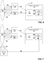
- system 700 that reduces emissions when a human body is detected, according to an embodiment of the subject disclosure.
- system 700 can be implemented within a portable electronic device, such as a mobile communications device, a tablet computing device, a laptop computing device, or the like.
- RF EMF emissions EMF radiation power control in electronic RF devices
- System 700 provides a way to detect proximity of a person to an EMF radiation source, which can provide safer usage conditions for the electronic device by reducing RF EMF emissions (EMF power) in the presence of a human body, while providing optimal RF transmissions ( e.g. , wireless transmissions).
- System 700 in an embodiment, is a low-cost and miniaturized electronic body detection system that can discriminate between a human body and an inanimate object. If a human body is detected in proximity, system 700 can facilitate reduction in RF EMF emissions. System 700 can provide significant advantages for manufacturers of electronic devices with RF EMF radiation sources to meet stringent criteria for emission regulations and specific absorption rate (SAR) standards.
- SAR specific absorption rate
- System 700 utilizes sensors 108, 110 of different sizes and electronic component 116 to facilitate the detection of a human body in proximity (detecting that an object 102 is a human body rather than an inanimate object).
- the electronic component 116 can employ a proximity detection algorithm that can processes signals 604 and 606 from ADC 602 that contain capacitance values C1 and C2.
- the proximity detection algorithm can also utilize the difference (C2 - C1) and a ratio (C2 / C1), which vary differently depending of the type of object 102 that the sensors 108, 112 are facing to facilitate discrimination of the object 102 between a human body and an inanimate object.
- the electronic component 116 can send a signal 702 (e.g., a feedback signal) to an emission control device 704 of the electronic device.
- the emission control device 704 can limit RF EMF emissions 706 (in other words limit RF output power). Therefore, RF EMF radiation exposure is limited for the detected human body in proximity to the electronic device.
- the electromagnetic radiation power or the exposure time from a radiation source can be limited.
- FIGs. 8-10 show methods illustrated as flow diagrams.
- the methods are depicted and described as series of acts.
- the methods are not limited by the acts illustrated and by the order of acts.
- acts can occur in various orders and/or concurrently, and with other acts not presented and described herein.
- not all illustrated acts may be required to implement the methods.
- the methods can be implemented on an article of manufacture (e.g ., within a portable electronic device) to facilitate transporting and transferring the methods.
- a first capacitance from a first sensor with a first shape (area, perimeter, circumference, or the like) and a second capacitance from a second sensor with a second shape different shape are processed.
- the first sensor and the second sensor can be capacitive sensors.
- the first sensor and the second sensor can be made of a conductive material.
- the first sensor and the second sensor have different shapes (e.g., one or more of different areas, different perimeters, or different circumferences) or configurations.
- the first sensor and the second sensor can be located near to each other ( FIG. 2 ), in a two-dimensionally symmetrical arrangement ( FIGs. 3 and 4 ), or in a fully-symmetrical arrangement ( FIG. 5 ).
- the first capacitance and the second capacitance are caused by an object in proximity to the first sensor and the second sensor.
- a type of object in proximity of the first sensor and the second sensor can be determined (e.g. , by electronic component 116) based on the first capacitance and the second capacitance. Additionally, the determination can also utilize a difference between the first capacitance and the second capacitance and/or a ratio between the first capacitance and the second capacitance.
- the determination can be accomplished according to a proximity detection algorithm (stored in the memory and executed by the processor) that utilizes the first capacitance, the second capacitance, the difference between the first capacitance and the second capacitance, and the ratio between the first capacitance and the second capacitance to sense proximity of the object and/or to facilitate determination of whether the object is a human body or an inanimate object.
- a proximity detection algorithm stored in the memory and executed by the processor
- the total equivalent capacitance between an approaching object and the two sensors is the sum of parallel plate (area) and fringe (perimeter or circumference) capacitances.
- the EMF lines between the object and each sensor will vary differently over time.
- the capacitance profiles over time also depend on the size and dielectric nature of the material of the object approaching. It is, therefore, possible to discriminate between objects with different properties, such as a human body and an inanimate object.
- the proximity detection algorithm processes signals that contain capacitance information profiles over time using the absolute values (C1 and C2) as well as their difference (C2 - C1) and ratio (C2 / C1), which vary differently depending of the type of object that the sensors are facing. This allows for discrimination of the object between a human body and an inanimate object.
- FIG. 9 illustrated is a process flow diagram of a method 900 for discriminating between a human body and an inanimate object based on digital signals, according to an embodiment of the subject disclosure.
- the sensors are capacitive sensors of two different shapes.
- the sensors sense capacitances caused by an object in proximity (e.g ., to an electronic device or to a radiation/emissions source).
- the sensors send analog signals of the capacitances for further processing.
- the analog capacitance signals from the two sensors of different sizes are converted to digital signals.
- the conversion can be accomplished by an analog-to-digital converter.
- the conversion can be accomplished by a time-multiplexed capacitance-to-digital converter, which can measure capacitance values (C1 and C2).
- the digital signals can be processed ( e.g., by a digital signal processor) to determine the type of object (human body or inanimate object) that caused the capacitances.
- the digital signals can be processed according to a proximity detection algorithm (stored in the memory and executed by the processor) that utilizes the first capacitance (C1), the second capacitance (C2), the difference between the first capacitance and the second capacitance (C2 - C1), and the ratio between the first capacitance and the second capacitance (C2 / C1) to sense proximity of the object and/or to facilitate determination of whether the object is a human body or an inanimate object.
- a proximity detection algorithm stored in the memory and executed by the processor
- the total equivalent capacitance between an approaching object and the two sensors is the sum of parallel plate (area) and fringe (perimeter or circumference) capacitances.
- the EMF lines between the object and each sensor will vary differently over time.
- the capacitance profiles over time also depend on the size and dielectric nature of the material of the object approaching. It is, therefore, possible to discriminate between objects with different properties, such as a human body and an inanimate object, such as: a table, a seat, a bag, or the like.
- the proximity detection algorithm processes signals that contain capacitance information profiles over time using the absolute values (C1 and C2) as well as their difference (C2 - C1) and ratio (C2 / C1), which vary differently depending of the type of object that the sensors are facing. This allows for discrimination of the object between a human body and an inanimate object.
- a human body is sensed in proximity to a radiation source.
- Sensors of different sizes sense capacitances caused by an object in proximity to the sensors.
- the capacitances can be used ( e.g ., according to a proximity detection algorithm) to determine if the object is a human body or an inanimate object.
- radiation emissions are reduced when a human body is sensed in proximity to the sensors and/or the radiation emitter.
- a signal e.g., a feedback signal
- the emission control device can limit RF EMF emissions (in other words limit RF output power). Therefore, RF EMF radiation exposure is limited for the detected human body in proximity to the electronic device.
- the electromagnetic radiation power or the exposure time from a radiation source can be limited.
- Method 1000 can provide significant advantages for manufacturers of electronic devices with RF EMF radiation sources to meet stringent criteria for emission regulations and specific absorption rate (SAR) standards by reducing radiation when a human body is in proximity to the electronic device.
- SAR specific absorption rate
- the word "example” is used herein to mean serving as an example, instance, or illustration.
- the subject matter described herein is not limited by such examples.
- any aspect or design described herein as an “example” is not necessarily to be construed as preferred or advantageous over other aspects or designs, nor is it meant to preclude equivalent structures and techniques known to those of ordinary skill in the art.
- the terms “includes,” “has,” “contains,” and other similar words are used in either the detailed description or the claims, such terms are intended to be inclusive - in a manner similar to the term “comprising” as an open transition word - without precluding any additional or other elements.
Landscapes
- Engineering & Computer Science (AREA)
- Computer Networks & Wireless Communication (AREA)
- Signal Processing (AREA)
- Measurement Of Length, Angles, Or The Like Using Electric Or Magnetic Means (AREA)
- Electronic Switches (AREA)
- Geophysics And Detection Of Objects (AREA)
- Physics & Mathematics (AREA)
- General Physics & Mathematics (AREA)
Claims (14)
- System, umfassend:einen ersten Sensor (108) mit einer ersten Form, worin der erst Sensor angepasst ist, um eine erste auf ein Objekt (102) bezogene Kapazität zu erkennen;einen zweiten Sensor (110) mit einer zweiten Form, welche sich von der ersten Form unterscheidet, worin der zweite Sensor angepasst ist, um eine zweite objekt-bezogene Kapazität zu erkennen; undeine elektronische Komponente (116), welche angepasst ist, um die erste Kapazität und die zweite Kapazität zu verarbeiten, um einen Ausgangswert zu liefern, worin der Ausgangswert die Unterscheidung erleichtert, ob das Objekt ein menschlicher Körper oder ein nicht-menschliches Objekt ist, auf Grundlage von Kapazitätsprofildaten, die mit den verschiedenen dielektrischen Eigenschaften des menschlichen Körpers oder des nicht-menschliches Objekts verbunden sind, undworin der erste Sensor und der zweite Sensor von einer Abschirmung umgeben sind,gekennzeichnet durch die Abschirmung, gekoppelt mit einem aktiven Vorspannungstreiber, angepasst, um eine dem ersten Sensor und dem zweiten Sensor entsprechende Spannung zu verfolgen,und eine Strahlungsquelle (704), welche angepasst ist, um ein Emittieren der Strahlung (706) als Reaktion auf eine auf der ersten Kapazität und der zweiten Kapazität basierende Bestimmung, dass das Objekt (102) ein menschlicher Körper ist, zu ändern.
- System gemäss Anspruch 1, worin der erste Sensor (108) eine erste Fläche und einen ersten Umfang aufweist, worin der zweite Sensor (110) eine zweite Fläche und einen zweiten Umfang aufweist; und worin die erste Fläche sich von der zweiten Fläche unterscheidet.
- System gemäss Anspruch 1 oder 2, worin der erste Sensor (108) eine erste Fläche und einen ersten Umfang aufweist, worin der zweite Sensor (110) eine zweite Fläche und einen zweiten Umfang aufweist; und worin der erste Umfang sich vom zweiten Umfang unterscheidet.
- System gemäss irgendeinem der Ansprüche 1 bis 3, worin die elektronische Komponente (116) die Unterscheidung auf der Grundlage einer Summe von Kapazitäten einschliesslich der ersten Kapazität und der zweiten Kapazität erleichtert.
- System gemäss irgendeinem der Ansprüche 1 bis 4, worin die elektronische Komponente (116) angepasst ist, die Unterscheidung auf der Grundlage eines Unterschieds zwischen der ersten Kapazität und der zweiten Kapazität zu erleichtern.
- System gemäss irgendeinem der Ansprüche 1 bis 6, worin die elektronische Komponente (116) angepasst ist, um auf der Grundlage des Verhältnisses der ersten Kapazität und der zweiten Kapazität zu bestimmen, ob das Objekt (102) der menschliche Körper oder das nicht-menschliche Objekt ist.
- System gemäss irgendeinem der Ansprüche 1 bis 6, worin die elektronische Komponente (116) umfasst:einen Analog-Digital-Wandler (602), welcher angepasst ist, um die erste Kapazität und die zweite Kapazität in ein erstes digitales Signal (606) und ein zweites digitales Signal (604) umzuwandeln; undeine digitale Verarbeitungseinheit (608), welche angepasst ist, um auf der Grundlage des ersten digitalen Signals und des zweiten digitalen Signals zu bestimmen, ob das Objekt (102) der menschliche Körper oder das nicht-menschliche Objekt ist.
- System gemäss irgendeinem der Ansprüche 1 bis 6, zudem umfassend eine Strahlungsquelle (706), welche angepasst ist, um die elektromagnetische Strahlungsleistung als Reaktion auf eine auf der ersten Kapazität und der zweiten Kapazität basierende Bestimmung, dass das Objekt (102) ein menschlicher Körper ist, zu begrenzen.
- System gemäss irgendeinem der Ansprüche 1 bis 8, worin der erste Sensor (108) und der zweite Sensor (110) ein leitfähiges Material aufweisen.
- System gemäss irgendeinem der Ansprüche 1 bis 9, worin die elektronische Komponente (116) einen zeitlich gemultiplexten Kapazitäts-Digital-Wandler umfasst.
- Verfahren, umfassend:Bestimmen einer ersten Kapazität unter Verwendung eines ersten Sensors (108) entsprechend einer ersten Form;Bestimmen einer zweiten Kapazität unter Verwendung eines ersten Sensors (110) entsprechend einer zweiten Form, welche sich von der ersten Form unterscheidet; undBestimmen eines Typs eines Objekts (102) aus einem Satz von Objekten mit verschiedenen dielektrischen Eigenschaften, welches sich in der Nähe des ersten Sensors und des zweiten Sensors befindet, auf Grundlage der Kapazitätsprofildaten, die mit den verschiedenen dielektrischen Eigenschaften des Satzes von Objekten verbunden sind,worin der erste Sensor und der zweite Sensor von einer Abschirmung umgeben sind,gekennzeichnet durch die Abschirmung, gekoppelt mit einem aktiven Vorspannungstreiber, angepasst, um eine dem ersten Sensor und dem zweiten Sensor entsprechende Spannung zu verfolgen, undÄndern des Emittierens einer Strahlungsquelle (704) als Reaktion auf eine auf der ersten Kapazität und der zweiten Kapazität basierende Bestimmung, dass das Objekt (102) ein menschlicher Körper ist.
- Verfahren gemäss Anspruch 11, worin der erste Sensor (108) eine erste Fläche und einen ersten Umfang aufweist, worin der zweite Sensor (110) eine zweite Fläche und einen zweiten Umfang aufweist; und worin die erste Fläche sich von der zweiten Fläche unterscheidet; oder
worin der erste Sensor (108) eine erste Fläche und einen ersten Umfang aufweist, worin der zweite Sensor (110) eine zweite Fläche und einen zweiten Umfang aufweist; und worin der erste Umfang sich vom zweiten Umfang unterscheidet. - Verfahren gemäss Anspruch 11 oder 12, worin das Bestimmen umfasst: das Berechnen einer Differenz zwischen der ersten Kapazität und der zweiten Kapazität; und das Bestimmen des Objekttyps auf Grundlage der Differenz.
- Verfahren gemäss Anspruch 11 oder 12, worin das Bestimmen umfasst: das Berechnen eines Verhältnisses zwischen der ersten Kapazität und der zweiten Kapazität; und das Bestimmen des Objekttyps auf Grundlage der Differenz.
Applications Claiming Priority (2)
| Application Number | Priority Date | Filing Date | Title |
|---|---|---|---|
| US13/549,017 US9979389B2 (en) | 2012-07-13 | 2012-07-13 | Capacitive body proximity sensor system |
| PCT/US2013/048961 WO2014011436A1 (en) | 2012-07-13 | 2013-07-01 | Capacitive body proximity sensor system |
Publications (3)
| Publication Number | Publication Date |
|---|---|
| EP2872905A1 EP2872905A1 (de) | 2015-05-20 |
| EP2872905A4 EP2872905A4 (de) | 2016-03-09 |
| EP2872905B1 true EP2872905B1 (de) | 2019-03-06 |
Family
ID=49913486
Family Applications (1)
| Application Number | Title | Priority Date | Filing Date |
|---|---|---|---|
| EP13817134.3A Active EP2872905B1 (de) | 2012-07-13 | 2013-07-01 | Kapazitiver körpernäherungssensorsystem |
Country Status (5)
| Country | Link |
|---|---|
| US (1) | US9979389B2 (de) |
| EP (1) | EP2872905B1 (de) |
| KR (1) | KR102079413B1 (de) |
| CN (1) | CN104769446B (de) |
| WO (1) | WO2014011436A1 (de) |
Cited By (1)
| Publication number | Priority date | Publication date | Assignee | Title |
|---|---|---|---|---|
| EP4210227A1 (de) * | 2022-01-06 | 2023-07-12 | Semtech Corporation | Näherungssensor für eine tragbare drahtlose vorrichtung |
Families Citing this family (45)
| Publication number | Priority date | Publication date | Assignee | Title |
|---|---|---|---|---|
| US9176597B2 (en) * | 2012-07-02 | 2015-11-03 | Stmicroelectronics Asia Pacific Pte Ltd | Directional capacitive proximity sensor with bootstrapping |
| US9236861B2 (en) | 2012-07-02 | 2016-01-12 | Stmicroelectronics Asia Pacific Pte Ltd | Capacitive proximity sensor with enabled touch detection |
| US9164629B2 (en) | 2012-08-06 | 2015-10-20 | Stmicroelectronics Asia Pacific Pte Ltd | Touch screen panel with slide feature |
| CN104122974B (zh) * | 2013-04-24 | 2017-07-18 | 华硕电脑股份有限公司 | 具有识别人体功能的移动通信装置 |
| US9871544B2 (en) | 2013-05-29 | 2018-01-16 | Microsoft Technology Licensing, Llc | Specific absorption rate mitigation |
| US10893488B2 (en) | 2013-06-14 | 2021-01-12 | Microsoft Technology Licensing, Llc | Radio frequency (RF) power back-off optimization for specific absorption rate (SAR) compliance |
| US9813997B2 (en) | 2014-01-10 | 2017-11-07 | Microsoft Technology Licensing, Llc | Antenna coupling for sensing and dynamic transmission |
| US10044095B2 (en) | 2014-01-10 | 2018-08-07 | Microsoft Technology Licensing, Llc | Radiating structure with integrated proximity sensing |
| US9454272B2 (en) | 2014-05-22 | 2016-09-27 | Stmicroelectronics Asia Pacific Pte Ltd | Touch screen for stylus emitting wireless signals |
| US9769769B2 (en) | 2014-06-30 | 2017-09-19 | Microsoft Technology Licensing, Llc | Detecting proximity using antenna feedback |
| US9785174B2 (en) | 2014-10-03 | 2017-10-10 | Microsoft Technology Licensing, Llc | Predictive transmission power control for back-off |
| JP2016100099A (ja) * | 2014-11-19 | 2016-05-30 | アイシン精機株式会社 | 車両用操作検出装置 |
| US9871545B2 (en) | 2014-12-05 | 2018-01-16 | Microsoft Technology Licensing, Llc | Selective specific absorption rate adjustment |
| US11078652B2 (en) | 2014-12-18 | 2021-08-03 | Delta Faucet Company | Faucet including capacitive sensors for hands free fluid flow control |
| US10301801B2 (en) | 2014-12-18 | 2019-05-28 | Delta Faucet Company | Faucet including capacitive sensors for hands free fluid flow control |
| GB2536475B (en) * | 2015-03-18 | 2018-02-14 | Jaguar Land Rover Ltd | Reducing erroneous detection of input command gestures |
| JP2017069651A (ja) * | 2015-09-28 | 2017-04-06 | 京セラ株式会社 | 電子機器、制御方法、及び制御プログラム |
| US10013038B2 (en) | 2016-01-05 | 2018-07-03 | Microsoft Technology Licensing, Llc | Dynamic antenna power control for multi-context device |
| US10114968B2 (en) | 2016-02-19 | 2018-10-30 | International Business Machines Corporation | Proximity based content security |
| CN107402319A (zh) * | 2016-05-19 | 2017-11-28 | 苏州明皜传感科技有限公司 | 量测微电容的探针卡 |
| US9838061B1 (en) | 2016-11-11 | 2017-12-05 | Lenovo (Singapore) Pte. Ltd. | Portable electronic communications device with human tissue contact detection |
| US10461406B2 (en) | 2017-01-23 | 2019-10-29 | Microsoft Technology Licensing, Llc | Loop antenna with integrated proximity sensing |
| US10795196B2 (en) * | 2017-02-02 | 2020-10-06 | Sharp Kabushiki Kaisha | Display device |
| CN107172268B (zh) * | 2017-03-24 | 2021-01-15 | 联想(北京)有限公司 | 一种功率控制方法及电子设备 |
| US10224974B2 (en) | 2017-03-31 | 2019-03-05 | Microsoft Technology Licensing, Llc | Proximity-independent SAR mitigation |
| CN111414013B (zh) * | 2017-04-19 | 2023-02-10 | 金钱猫科技股份有限公司 | 一种目标物预警监测的方法和装置 |
| EP3402074B1 (de) * | 2017-05-12 | 2022-04-06 | Semtech Corporation | Näherungssensor mit nichtlinearem filter und verfahren |
| EP3404835B1 (de) | 2017-05-16 | 2020-09-09 | Semtech Corporation | Einzelsensornäherungsdetektor |
| US11128298B2 (en) * | 2017-06-27 | 2021-09-21 | Semtech Corporation | Advanced capacitive proximity sensor |
| DE102017215333A1 (de) | 2017-09-01 | 2019-03-07 | Witte Automotive Gmbh | Kapazitive Sensoranordnung und Fahrzeugaußengriff |
| WO2019055956A1 (en) | 2017-09-18 | 2019-03-21 | Semtech Corporation | SYSTEM AND METHOD FOR POWER TRANSMISSION AND WIRELESS COMMUNICATION |
| JP6876815B2 (ja) * | 2017-09-29 | 2021-05-26 | アルプスアルパイン株式会社 | 操作入力装置及びドアハンドル |
| DE102018005248B4 (de) * | 2018-06-30 | 2024-07-18 | Kostal Automobil Elektrik Gmbh & Co. Kg | Kapazitives Sensorsystem zur Berührungserkennung |
| US11082550B2 (en) * | 2018-07-09 | 2021-08-03 | Semtech Corporation | Proximity sensor and mobile wireless device |
| DE102019007410A1 (de) * | 2018-10-30 | 2020-04-30 | Marquardt Gmbh | Schaltelement |
| US10996736B2 (en) | 2019-03-07 | 2021-05-04 | International Business Machines Corporation | Wireless capacitive presence detection |
| CN111511006B (zh) * | 2020-04-21 | 2023-03-24 | Oppo广东移动通信有限公司 | 天线发射功率的调节方法、装置及移动终端 |
| CN211180797U (zh) * | 2020-06-23 | 2020-08-04 | 深圳市汇顶科技股份有限公司 | 电容检测装置和电子设备 |
| CN111998764A (zh) * | 2020-08-25 | 2020-11-27 | 上海艾为电子技术股份有限公司 | 一种接近感应检测方法及装置、电子设备 |
| KR20220033045A (ko) * | 2020-09-07 | 2022-03-15 | 선전 구딕스 테크놀로지 컴퍼니, 리미티드 | 접근 검출 장치 및 전자장치 |
| CN112520522A (zh) * | 2020-10-28 | 2021-03-19 | 康拓科技太仓有限公司 | 电梯控制器和电梯控制方法 |
| CN113784268A (zh) * | 2021-08-09 | 2021-12-10 | 深圳曦华科技有限公司 | 入耳检测方法及相关装置 |
| CN115732897B (zh) * | 2021-09-01 | 2026-05-08 | Oppo广东移动通信有限公司 | 电子设备及控制电子设备sar的方法 |
| JP7592053B2 (ja) | 2021-09-29 | 2024-11-29 | セムテック コーポレイション | 環境センサ回路を備えた携帯型接続無線装置 |
| CN115854846B (zh) * | 2022-11-23 | 2026-06-19 | 珠海格力电器股份有限公司 | 距离确定方法和状态控制方法 |
Citations (1)
| Publication number | Priority date | Publication date | Assignee | Title |
|---|---|---|---|---|
| US20120074961A1 (en) * | 2010-09-29 | 2012-03-29 | Kopin Corporation | Capacitive sensor with active shield electrode |
Family Cites Families (27)
| Publication number | Priority date | Publication date | Assignee | Title |
|---|---|---|---|---|
| US6750624B2 (en) * | 2001-10-17 | 2004-06-15 | Delphi Technologies, Inc. | Non-contact obstacle detection system utilizing ultra sensitive capacitive sensing |
| US6657595B1 (en) | 2002-05-09 | 2003-12-02 | Motorola, Inc. | Sensor-driven adaptive counterpoise antenna system |
| EP1593988A4 (de) | 2002-12-25 | 2009-01-14 | Act Elsi Inc | Näherungssensor zur bestimmung der elektrostatischen kapazität |
| CN100544195C (zh) * | 2004-08-16 | 2009-09-23 | 李应流 | 线性电容测量和非接触开关 |
| US8077032B1 (en) | 2006-05-05 | 2011-12-13 | Motion Computing, Inc. | System and method for selectively providing security to and transmission power from a portable electronic device depending on a distance between the device and a user |
| EP1860776A3 (de) * | 2006-05-26 | 2010-08-11 | Fujikura Ltd. | Näherungssensor und Verfahren zur Näherungsdetektion |
| GB2456937B (en) | 2006-10-24 | 2011-07-13 | Bradley Fixtures Corp | Capacitive sensing for washroom fixture |
| US8547114B2 (en) | 2006-11-14 | 2013-10-01 | Cypress Semiconductor Corporation | Capacitance to code converter with sigma-delta modulator |
| DE102006058873A1 (de) * | 2006-12-06 | 2008-06-12 | E.G.O. Elektro-Gerätebau GmbH | Bedienungseinrichtung für ein Elektrogerät mit Berührungsschaltern und Verfahren zum Zuschalten einer Zusatz-Heizeinrichtung |
| EP2187241B1 (de) | 2007-10-04 | 2018-09-19 | Fujikura Ltd. | Kapazitiver nährungssensor und vefahren zur näherungsdetektion |
| DE102007048402A1 (de) | 2007-10-09 | 2009-04-16 | Gerd Reime | Bedieneinheit und Verfahren zur Auslösung einer Funktion |
| US8417296B2 (en) | 2008-06-05 | 2013-04-09 | Apple Inc. | Electronic device with proximity-based radio power control |
| WO2010026845A1 (ja) * | 2008-09-03 | 2010-03-11 | Mizushima Masanori | 入力装置 |
| JP5267932B2 (ja) | 2008-11-11 | 2013-08-21 | 株式会社フジクラ | 位置検出装置 |
| US20100317302A1 (en) | 2009-06-12 | 2010-12-16 | Novatel Wireless | System and method for controlling rf explosure levels |
| US8466839B2 (en) * | 2009-07-17 | 2013-06-18 | Apple Inc. | Electronic devices with parasitic antenna resonating elements that reduce near field radiation |
| US8432322B2 (en) | 2009-07-17 | 2013-04-30 | Apple Inc. | Electronic devices with capacitive proximity sensors for proximity-based radio-frequency power control |
| WO2011024306A1 (ja) | 2009-08-31 | 2011-03-03 | Nonogaki Keiichi | 静電容量型近接センサ |
| US8294601B2 (en) * | 2009-11-13 | 2012-10-23 | Research In Motion Limited | Detection of intended key activation on a mobile device |
| US8669772B2 (en) * | 2010-03-04 | 2014-03-11 | Franklin Sensors, Inc. | Obscured feature detector housing |
| WO2011149750A2 (en) * | 2010-05-25 | 2011-12-01 | 3M Innovative Properties Company | High speed low power multi-touch touch device and controller therefor |
| US9459736B2 (en) * | 2010-10-12 | 2016-10-04 | Parade Technologies, Ltd. | Flexible capacitive sensor array |
| JP5316527B2 (ja) * | 2010-12-14 | 2013-10-16 | 株式会社日本自動車部品総合研究所 | 静電容量式乗員検知装置 |
| US9026059B2 (en) * | 2011-02-17 | 2015-05-05 | Futurewei Technologies, Inc. | Adaptive maximum power limiting using capacitive sensing in a wireless device |
| CN202206357U (zh) * | 2011-08-17 | 2012-04-25 | 张正儒 | 自给式设备的非接触感应装置 |
| JP5382080B2 (ja) * | 2011-09-10 | 2014-01-08 | 株式会社デンソー | 燃料性状検出装置 |
| US20130098941A1 (en) * | 2011-10-25 | 2013-04-25 | Gojo Industries, Inc. | Proprietary dispensing container system |
-
2012
- 2012-07-13 US US13/549,017 patent/US9979389B2/en active Active
-
2013
- 2013-07-01 KR KR1020157003860A patent/KR102079413B1/ko active Active
- 2013-07-01 WO PCT/US2013/048961 patent/WO2014011436A1/en not_active Ceased
- 2013-07-01 CN CN201380046321.9A patent/CN104769446B/zh active Active
- 2013-07-01 EP EP13817134.3A patent/EP2872905B1/de active Active
Patent Citations (1)
| Publication number | Priority date | Publication date | Assignee | Title |
|---|---|---|---|---|
| US20120074961A1 (en) * | 2010-09-29 | 2012-03-29 | Kopin Corporation | Capacitive sensor with active shield electrode |
Cited By (2)
| Publication number | Priority date | Publication date | Assignee | Title |
|---|---|---|---|---|
| EP4210227A1 (de) * | 2022-01-06 | 2023-07-12 | Semtech Corporation | Näherungssensor für eine tragbare drahtlose vorrichtung |
| US12278628B2 (en) | 2022-01-06 | 2025-04-15 | Semtech Corporation | Proximity sensor for portable wireless device |
Also Published As
| Publication number | Publication date |
|---|---|
| EP2872905A4 (de) | 2016-03-09 |
| EP2872905A1 (de) | 2015-05-20 |
| KR20150047486A (ko) | 2015-05-04 |
| KR102079413B1 (ko) | 2020-04-02 |
| US20140015595A1 (en) | 2014-01-16 |
| US9979389B2 (en) | 2018-05-22 |
| CN104769446A (zh) | 2015-07-08 |
| WO2014011436A1 (en) | 2014-01-16 |
| CN104769446B (zh) | 2019-06-21 |
| WO2014011436A4 (en) | 2014-06-26 |
Similar Documents
| Publication | Publication Date | Title |
|---|---|---|
| US9979389B2 (en) | Capacitive body proximity sensor system | |
| US9258026B2 (en) | Mobile communication device with human body recognition function | |
| TWI599188B (zh) | 用於wi-fi保護之電容性/電感性鄰近偵測 | |
| CN108873080B (zh) | 单个传感器接近度检测器 | |
| TWI463386B (zh) | A method and an apparatus for improving noise interference of a capacitive touch device | |
| US9632644B2 (en) | Multi-channel contact sensing apparatus | |
| CN108917797B (zh) | 具有非线性滤波器的接近度传感器和方法 | |
| US9442598B2 (en) | Detecting interference in an input device having electrodes | |
| EP1592953A4 (de) | Berührungsdetektion für einen digitalisierer | |
| US11507230B2 (en) | Hybrid sensor for detecting touch and touch force and method of operating same | |
| CN107172268B (zh) | 一种功率控制方法及电子设备 | |
| CN117590376A (zh) | 用于目标运动检测的装置、电子设备和方法 | |
| CN110554801B (zh) | 干扰检测 | |
| CN210006022U (zh) | 一种电容感应型手势检测装置及其电容感应型触控阵列 | |
| CN103646007A (zh) | 数据处理方法、装置及系统 | |
| CN103414456B (zh) | 具近接感测的侦测电路 | |
| WO2017152852A1 (en) | System and method of detection of object made with electrically poorly conductive material | |
| KR101977949B1 (ko) | 다중전극의 근접 센서를 이용한 장애물 회피 시스템 | |
| JP5730232B2 (ja) | 容量結合型センサ、センサを提供する方法、及び、そのためのコンピュータプログラム | |
| CN112099677A (zh) | 一种用电器及其电容感应型输入检测装置 | |
| WO2017079912A1 (en) | Fingerprint recognition system | |
| CN106200859B (zh) | 电容式指标装置的省电装置 | |
| TWI542989B (zh) | 電容式指標裝置之省電裝置 | |
| CN109542261A (zh) | 物体追踪方法以及物体追踪系统 | |
| JP2012173271A (ja) | 受動型人感装置 |
Legal Events
| Date | Code | Title | Description |
|---|---|---|---|
| PUAI | Public reference made under article 153(3) epc to a published international application that has entered the european phase |
Free format text: ORIGINAL CODE: 0009012 |
|
| 17P | Request for examination filed |
Effective date: 20150113 |
|
| AK | Designated contracting states |
Kind code of ref document: A1 Designated state(s): AL AT BE BG CH CY CZ DE DK EE ES FI FR GB GR HR HU IE IS IT LI LT LU LV MC MK MT NL NO PL PT RO RS SE SI SK SM TR |
|
| AX | Request for extension of the european patent |
Extension state: BA ME |
|
| DAX | Request for extension of the european patent (deleted) | ||
| RA4 | Supplementary search report drawn up and despatched (corrected) |
Effective date: 20160208 |
|
| RIC1 | Information provided on ipc code assigned before grant |
Ipc: H04B 1/3827 20150101ALN20160202BHEP Ipc: G01R 27/26 20060101AFI20160202BHEP Ipc: H03K 17/955 20060101ALI20160202BHEP |
|
| STAA | Information on the status of an ep patent application or granted ep patent |
Free format text: STATUS: EXAMINATION IS IN PROGRESS |
|
| 17Q | First examination report despatched |
Effective date: 20180611 |
|
| GRAP | Despatch of communication of intention to grant a patent |
Free format text: ORIGINAL CODE: EPIDOSNIGR1 |
|
| STAA | Information on the status of an ep patent application or granted ep patent |
Free format text: STATUS: GRANT OF PATENT IS INTENDED |
|
| RIC1 | Information provided on ipc code assigned before grant |
Ipc: H04B 1/3827 20150101ALN20180927BHEP Ipc: H03K 17/955 20060101ALI20180927BHEP Ipc: G01R 27/26 20060101AFI20180927BHEP |
|
| RIC1 | Information provided on ipc code assigned before grant |
Ipc: H04B 1/3827 20150101ALN20181001BHEP Ipc: H03K 17/955 20060101ALI20181001BHEP Ipc: G01R 27/26 20060101AFI20181001BHEP |
|
| INTG | Intention to grant announced |
Effective date: 20181030 |
|
| RIN1 | Information on inventor provided before grant (corrected) |
Inventor name: HOFFMANN, MATHIEU Inventor name: MONNEY, PASCAL Inventor name: VAN AUSDALL, TERRENCE LEES |
|
| GRAS | Grant fee paid |
Free format text: ORIGINAL CODE: EPIDOSNIGR3 |
|
| GRAA | (expected) grant |
Free format text: ORIGINAL CODE: 0009210 |
|
| STAA | Information on the status of an ep patent application or granted ep patent |
Free format text: STATUS: THE PATENT HAS BEEN GRANTED |
|
| AK | Designated contracting states |
Kind code of ref document: B1 Designated state(s): AL AT BE BG CH CY CZ DE DK EE ES FI FR GB GR HR HU IE IS IT LI LT LU LV MC MK MT NL NO PL PT RO RS SE SI SK SM TR |
|
| REG | Reference to a national code |
Ref country code: GB Ref legal event code: FG4D |
|
| REG | Reference to a national code |
Ref country code: CH Ref legal event code: EP Ref country code: AT Ref legal event code: REF Ref document number: 1105266 Country of ref document: AT Kind code of ref document: T Effective date: 20190315 |
|
| REG | Reference to a national code |
Ref country code: DE Ref legal event code: R096 Ref document number: 602013051962 Country of ref document: DE |
|
| REG | Reference to a national code |
Ref country code: IE Ref legal event code: FG4D |
|
| REG | Reference to a national code |
Ref country code: NL Ref legal event code: MP Effective date: 20190306 |
|
| REG | Reference to a national code |
Ref country code: LT Ref legal event code: MG4D |
|
| PG25 | Lapsed in a contracting state [announced via postgrant information from national office to epo] |
Ref country code: SE Free format text: LAPSE BECAUSE OF FAILURE TO SUBMIT A TRANSLATION OF THE DESCRIPTION OR TO PAY THE FEE WITHIN THE PRESCRIBED TIME-LIMIT Effective date: 20190306 Ref country code: NO Free format text: LAPSE BECAUSE OF FAILURE TO SUBMIT A TRANSLATION OF THE DESCRIPTION OR TO PAY THE FEE WITHIN THE PRESCRIBED TIME-LIMIT Effective date: 20190606 Ref country code: FI Free format text: LAPSE BECAUSE OF FAILURE TO SUBMIT A TRANSLATION OF THE DESCRIPTION OR TO PAY THE FEE WITHIN THE PRESCRIBED TIME-LIMIT Effective date: 20190306 Ref country code: LT Free format text: LAPSE BECAUSE OF FAILURE TO SUBMIT A TRANSLATION OF THE DESCRIPTION OR TO PAY THE FEE WITHIN THE PRESCRIBED TIME-LIMIT Effective date: 20190306 |
|
| PG25 | Lapsed in a contracting state [announced via postgrant information from national office to epo] |
Ref country code: GR Free format text: LAPSE BECAUSE OF FAILURE TO SUBMIT A TRANSLATION OF THE DESCRIPTION OR TO PAY THE FEE WITHIN THE PRESCRIBED TIME-LIMIT Effective date: 20190607 Ref country code: BG Free format text: LAPSE BECAUSE OF FAILURE TO SUBMIT A TRANSLATION OF THE DESCRIPTION OR TO PAY THE FEE WITHIN THE PRESCRIBED TIME-LIMIT Effective date: 20190606 Ref country code: RS Free format text: LAPSE BECAUSE OF FAILURE TO SUBMIT A TRANSLATION OF THE DESCRIPTION OR TO PAY THE FEE WITHIN THE PRESCRIBED TIME-LIMIT Effective date: 20190306 Ref country code: NL Free format text: LAPSE BECAUSE OF FAILURE TO SUBMIT A TRANSLATION OF THE DESCRIPTION OR TO PAY THE FEE WITHIN THE PRESCRIBED TIME-LIMIT Effective date: 20190306 Ref country code: HR Free format text: LAPSE BECAUSE OF FAILURE TO SUBMIT A TRANSLATION OF THE DESCRIPTION OR TO PAY THE FEE WITHIN THE PRESCRIBED TIME-LIMIT Effective date: 20190306 Ref country code: LV Free format text: LAPSE BECAUSE OF FAILURE TO SUBMIT A TRANSLATION OF THE DESCRIPTION OR TO PAY THE FEE WITHIN THE PRESCRIBED TIME-LIMIT Effective date: 20190306 |
|
| REG | Reference to a national code |
Ref country code: AT Ref legal event code: MK05 Ref document number: 1105266 Country of ref document: AT Kind code of ref document: T Effective date: 20190306 |
|
| PG25 | Lapsed in a contracting state [announced via postgrant information from national office to epo] |
Ref country code: SK Free format text: LAPSE BECAUSE OF FAILURE TO SUBMIT A TRANSLATION OF THE DESCRIPTION OR TO PAY THE FEE WITHIN THE PRESCRIBED TIME-LIMIT Effective date: 20190306 Ref country code: RO Free format text: LAPSE BECAUSE OF FAILURE TO SUBMIT A TRANSLATION OF THE DESCRIPTION OR TO PAY THE FEE WITHIN THE PRESCRIBED TIME-LIMIT Effective date: 20190306 Ref country code: IT Free format text: LAPSE BECAUSE OF FAILURE TO SUBMIT A TRANSLATION OF THE DESCRIPTION OR TO PAY THE FEE WITHIN THE PRESCRIBED TIME-LIMIT Effective date: 20190306 Ref country code: EE Free format text: LAPSE BECAUSE OF FAILURE TO SUBMIT A TRANSLATION OF THE DESCRIPTION OR TO PAY THE FEE WITHIN THE PRESCRIBED TIME-LIMIT Effective date: 20190306 Ref country code: AL Free format text: LAPSE BECAUSE OF FAILURE TO SUBMIT A TRANSLATION OF THE DESCRIPTION OR TO PAY THE FEE WITHIN THE PRESCRIBED TIME-LIMIT Effective date: 20190306 Ref country code: PT Free format text: LAPSE BECAUSE OF FAILURE TO SUBMIT A TRANSLATION OF THE DESCRIPTION OR TO PAY THE FEE WITHIN THE PRESCRIBED TIME-LIMIT Effective date: 20190706 Ref country code: CZ Free format text: LAPSE BECAUSE OF FAILURE TO SUBMIT A TRANSLATION OF THE DESCRIPTION OR TO PAY THE FEE WITHIN THE PRESCRIBED TIME-LIMIT Effective date: 20190306 Ref country code: ES Free format text: LAPSE BECAUSE OF FAILURE TO SUBMIT A TRANSLATION OF THE DESCRIPTION OR TO PAY THE FEE WITHIN THE PRESCRIBED TIME-LIMIT Effective date: 20190306 |
|
| PG25 | Lapsed in a contracting state [announced via postgrant information from national office to epo] |
Ref country code: PL Free format text: LAPSE BECAUSE OF FAILURE TO SUBMIT A TRANSLATION OF THE DESCRIPTION OR TO PAY THE FEE WITHIN THE PRESCRIBED TIME-LIMIT Effective date: 20190306 Ref country code: SM Free format text: LAPSE BECAUSE OF FAILURE TO SUBMIT A TRANSLATION OF THE DESCRIPTION OR TO PAY THE FEE WITHIN THE PRESCRIBED TIME-LIMIT Effective date: 20190306 |
|
| REG | Reference to a national code |
Ref country code: DE Ref legal event code: R097 Ref document number: 602013051962 Country of ref document: DE |
|
| PG25 | Lapsed in a contracting state [announced via postgrant information from national office to epo] |
Ref country code: AT Free format text: LAPSE BECAUSE OF FAILURE TO SUBMIT A TRANSLATION OF THE DESCRIPTION OR TO PAY THE FEE WITHIN THE PRESCRIBED TIME-LIMIT Effective date: 20190306 Ref country code: IS Free format text: LAPSE BECAUSE OF FAILURE TO SUBMIT A TRANSLATION OF THE DESCRIPTION OR TO PAY THE FEE WITHIN THE PRESCRIBED TIME-LIMIT Effective date: 20190706 |
|
| PLBE | No opposition filed within time limit |
Free format text: ORIGINAL CODE: 0009261 |
|
| STAA | Information on the status of an ep patent application or granted ep patent |
Free format text: STATUS: NO OPPOSITION FILED WITHIN TIME LIMIT |
|
| PG25 | Lapsed in a contracting state [announced via postgrant information from national office to epo] |
Ref country code: DK Free format text: LAPSE BECAUSE OF FAILURE TO SUBMIT A TRANSLATION OF THE DESCRIPTION OR TO PAY THE FEE WITHIN THE PRESCRIBED TIME-LIMIT Effective date: 20190306 |
|
| 26N | No opposition filed |
Effective date: 20191209 |
|
| PG25 | Lapsed in a contracting state [announced via postgrant information from national office to epo] |
Ref country code: MC Free format text: LAPSE BECAUSE OF FAILURE TO SUBMIT A TRANSLATION OF THE DESCRIPTION OR TO PAY THE FEE WITHIN THE PRESCRIBED TIME-LIMIT Effective date: 20190306 Ref country code: SI Free format text: LAPSE BECAUSE OF FAILURE TO SUBMIT A TRANSLATION OF THE DESCRIPTION OR TO PAY THE FEE WITHIN THE PRESCRIBED TIME-LIMIT Effective date: 20190306 |
|
| REG | Reference to a national code |
Ref country code: CH Ref legal event code: PL |
|
| REG | Reference to a national code |
Ref country code: DE Ref legal event code: R082 Ref document number: 602013051962 Country of ref document: DE Representative=s name: BECK & ROESSIG EUROPEAN PATENT ATTORNEYS, DE Ref country code: DE Ref legal event code: R082 Ref document number: 602013051962 Country of ref document: DE Representative=s name: BECK & ROESSIG - EUROPEAN PATENT ATTORNEYS, DE |
|
| PG25 | Lapsed in a contracting state [announced via postgrant information from national office to epo] |
Ref country code: TR Free format text: LAPSE BECAUSE OF FAILURE TO SUBMIT A TRANSLATION OF THE DESCRIPTION OR TO PAY THE FEE WITHIN THE PRESCRIBED TIME-LIMIT Effective date: 20190306 |
|
| REG | Reference to a national code |
Ref country code: BE Ref legal event code: MM Effective date: 20190731 |
|
| PG25 | Lapsed in a contracting state [announced via postgrant information from national office to epo] |
Ref country code: LI Free format text: LAPSE BECAUSE OF NON-PAYMENT OF DUE FEES Effective date: 20190731 Ref country code: BE Free format text: LAPSE BECAUSE OF NON-PAYMENT OF DUE FEES Effective date: 20190731 Ref country code: LU Free format text: LAPSE BECAUSE OF NON-PAYMENT OF DUE FEES Effective date: 20190701 Ref country code: CH Free format text: LAPSE BECAUSE OF NON-PAYMENT OF DUE FEES Effective date: 20190731 |
|
| PG25 | Lapsed in a contracting state [announced via postgrant information from national office to epo] |
Ref country code: IE Free format text: LAPSE BECAUSE OF NON-PAYMENT OF DUE FEES Effective date: 20190701 |
|
| PG25 | Lapsed in a contracting state [announced via postgrant information from national office to epo] |
Ref country code: CY Free format text: LAPSE BECAUSE OF FAILURE TO SUBMIT A TRANSLATION OF THE DESCRIPTION OR TO PAY THE FEE WITHIN THE PRESCRIBED TIME-LIMIT Effective date: 20190306 |
|
| PG25 | Lapsed in a contracting state [announced via postgrant information from national office to epo] |
Ref country code: HU Free format text: LAPSE BECAUSE OF FAILURE TO SUBMIT A TRANSLATION OF THE DESCRIPTION OR TO PAY THE FEE WITHIN THE PRESCRIBED TIME-LIMIT; INVALID AB INITIO Effective date: 20130701 Ref country code: MT Free format text: LAPSE BECAUSE OF FAILURE TO SUBMIT A TRANSLATION OF THE DESCRIPTION OR TO PAY THE FEE WITHIN THE PRESCRIBED TIME-LIMIT Effective date: 20190306 |
|
| PG25 | Lapsed in a contracting state [announced via postgrant information from national office to epo] |
Ref country code: MK Free format text: LAPSE BECAUSE OF FAILURE TO SUBMIT A TRANSLATION OF THE DESCRIPTION OR TO PAY THE FEE WITHIN THE PRESCRIBED TIME-LIMIT Effective date: 20190306 |
|
| P01 | Opt-out of the competence of the unified patent court (upc) registered |
Effective date: 20230530 |
|
| PGFP | Annual fee paid to national office [announced via postgrant information from national office to epo] |
Ref country code: DE Payment date: 20250729 Year of fee payment: 13 |
|
| PGFP | Annual fee paid to national office [announced via postgrant information from national office to epo] |
Ref country code: GB Payment date: 20250728 Year of fee payment: 13 |
|
| PGFP | Annual fee paid to national office [announced via postgrant information from national office to epo] |
Ref country code: FR Payment date: 20250725 Year of fee payment: 13 |