EP2873286B1 - Appareil et procédé pour configurer une liaison terrestre sans fil dans un système de communication sans fil - Google Patents
Appareil et procédé pour configurer une liaison terrestre sans fil dans un système de communication sans fil Download PDFInfo
- Publication number
- EP2873286B1 EP2873286B1 EP13816498.3A EP13816498A EP2873286B1 EP 2873286 B1 EP2873286 B1 EP 2873286B1 EP 13816498 A EP13816498 A EP 13816498A EP 2873286 B1 EP2873286 B1 EP 2873286B1
- Authority
- EP
- European Patent Office
- Prior art keywords
- code
- communication system
- link
- new
- old
- Prior art date
- Legal status (The legal status is an assumption and is not a legal conclusion. Google has not performed a legal analysis and makes no representation as to the accuracy of the status listed.)
- Active
Links
Images




Classifications
-
- H—ELECTRICITY
- H04—ELECTRIC COMMUNICATION TECHNIQUE
- H04W—WIRELESS COMMUNICATION NETWORKS
- H04W48/00—Access restriction; Network selection; Access point selection
- H04W48/08—Access restriction or access information delivery, e.g. discovery data delivery
-
- H—ELECTRICITY
- H04—ELECTRIC COMMUNICATION TECHNIQUE
- H04W—WIRELESS COMMUNICATION NETWORKS
- H04W24/00—Supervisory, monitoring or testing arrangements
- H04W24/02—Arrangements for optimising operational condition
-
- H—ELECTRICITY
- H04—ELECTRIC COMMUNICATION TECHNIQUE
- H04W—WIRELESS COMMUNICATION NETWORKS
- H04W72/00—Local resource management
- H04W72/20—Control channels or signalling for resource management
- H04W72/21—Control channels or signalling for resource management in the uplink direction of a wireless link, i.e. towards the network
-
- H—ELECTRICITY
- H04—ELECTRIC COMMUNICATION TECHNIQUE
- H04W—WIRELESS COMMUNICATION NETWORKS
- H04W88/00—Devices specially adapted for wireless communication networks, e.g. terminals, base stations or access point devices
- H04W88/02—Terminal devices
-
- H—ELECTRICITY
- H04—ELECTRIC COMMUNICATION TECHNIQUE
- H04W—WIRELESS COMMUNICATION NETWORKS
- H04W88/00—Devices specially adapted for wireless communication networks, e.g. terminals, base stations or access point devices
- H04W88/08—Access point devices
-
- H—ELECTRICITY
- H04—ELECTRIC COMMUNICATION TECHNIQUE
- H04W—WIRELESS COMMUNICATION NETWORKS
- H04W84/00—Network topologies
- H04W84/02—Hierarchically pre-organised networks, e.g. paging networks, cellular networks, WLAN [Wireless Local Area Network] or WLL [Wireless Local Loop]
- H04W84/04—Large scale networks; Deep hierarchical networks
- H04W84/042—Public Land Mobile systems, e.g. cellular systems
- H04W84/045—Public Land Mobile systems, e.g. cellular systems using private Base Stations, e.g. femto Base Stations, home Node B
-
- H—ELECTRICITY
- H04—ELECTRIC COMMUNICATION TECHNIQUE
- H04W—WIRELESS COMMUNICATION NETWORKS
- H04W92/00—Interfaces specially adapted for wireless communication networks
- H04W92/04—Interfaces between hierarchically different network devices
- H04W92/12—Interfaces between hierarchically different network devices between access points and access point controllers
-
- H—ELECTRICITY
- H04—ELECTRIC COMMUNICATION TECHNIQUE
- H04W—WIRELESS COMMUNICATION NETWORKS
- H04W92/00—Interfaces specially adapted for wireless communication networks
- H04W92/16—Interfaces between hierarchically similar devices
- H04W92/20—Interfaces between hierarchically similar devices between access points
Definitions
- the present disclosure relates to configuring a wireless back haul link in a wireless communication system.
- a wireless communication system has evolved to provide various high-speed large-capacity services to Mobile Stations (MSs).
- Examples of the wireless communication system include a High Speed Downlink Packet Access (HSDPA) mobile communication system, a High Speed Uplink Packet Access (HSUPA) mobile communication system, a Long-Term Evolution (LTE) mobile communication system, a LTE-Advanced (LTE-A) mobile communication system, a High Rate Packet Data (HRPD) mobile communication system proposed in a 3rd Generation Project Partnership 2 (3GPP2), and an Institute of Electrical and Electronics Engineers (IEEE) 802.16m mobile communication system.
- HSDPA High Speed Downlink Packet Access
- HSUPA High Speed Uplink Packet Access
- LTE Long-Term Evolution
- LTE-A LTE-Advanced
- HRPD High Rate Packet Data
- the wireless communication system has evolved to increase data rate for satisfying a data traffic need, so the wireless communication system actively considers using a super high frequency-ultra wideband scheme in which a super high frequency is used at an ultra wide band in order to increase the data rate.
- the super high frequency-ultra wideband scheme increases propagation loss, the propagation loss results in decreasing a propagation distance, so a service coverage of a Base Station (BS) is decreased.
- BS Base Station
- a beam forming scheme is a typical scheme in which the wireless communication system decreases propagation loss, so the wireless communication system uses the super high frequency-ultra wideband scheme and the beam forming scheme to increase a service coverage of a BS. Even if the wireless communication system uses the super high frequency-ultra wideband scheme and the beam forming scheme, data traffic increase in the wireless communication system results in an additional BS deployment. Recently, even if a service coverage is decreased according to the data traffic increase and system request, a need for a BS of which a size is small increases, so an additional BS deployment is resulted.
- a BS is additionally deployed in a wireless communication system, a link between a new BS and an old BS should be configured, a method for configuring the link between the new BS and the old BS in the wireless communication system will be described with reference to FIGs. 1 to 3 .
- FIG. 1 schematically illustrates a process for configuring a link between an old BS and a femto BS in a case that the femto BS is newly deployed as a new BS in a conventional wireless communication system.
- the wireless communication system includes an old BS 110 and a femto BS 120. If the femto BS 120 is newly deployed as a new BS in a situation in which the old BS 110 has been deployed in the wireless communication system, a Mobile Station (MS) may recognize that the femto BS 120 is newly deployed. After recognizing the newly deployed femto BS 120, the MS notifies the old BS 110 that the femto BS 120 is deployed, so the old BS 110 may recognize that the femto BS 120 is newly deployed.
- MS Mobile Station
- FIG. 2 schematically illustrates a process for configuring a link between an old BS and a relay BS in a case that the relay BS is newly deployed as a new BS in a conventional wireless communication system.
- the wireless communication system includes an old BS 210 and a relay BS 220. If the relay BS 220 is newly deployed as a new BS in a situation in which the old BS 210 has been deployed in the wireless communication system, the relay BS 220 configures a link with the old BS 210 by performing an initial network entry procedure like an MS (not shown in FIG. 2 ).
- FIG. 3 schematically illustrates a process for configuring a link between an old BS and a new BS in a case that the new BS is deployed in a conventional wireless communication system.
- the wireless communication system includes an old BS 310 and a new BS 320. If the new BS 320 is newly deployed in a situation in which the old BS 310 has been deployed, the wireless communication system configures a link between the old BS 310 and the new BS 320 by allocating a dedicated resource between the old BS 310 and the new BS 320. That is, the old BS 310 performs a signaling using a dedicated resource for configuring a back haul link between the old BS 310 and the new BS 320 as well as a signaling provided through an air link.
- the link configuration method among BSs described in FIGs. 1 to 3 has following problems.
- the femto BS 120 is newly deployed in a wireless communication system, there is a limitation in which the femto BS 120 should be connected to the old BS 110 through a wired back haul link.
- the relay BS 220 should be deployed within a service coverage of the old BS 210. So, a link coverage between the old BS 210 and the relay BS 220 may not exceed a link coverage between the old BS 210 and an MS.
- a signaling should be always performed for configuring a back haul link among BSs using a dedicated resource, so severe waste for power, frequencies, etc. is resulted and a service quality is severely decreased.
- EP 2083595 relates to a method and apparatuses for selecting a cell identifier in a cellular network, wherein a predetermined information indicating a search phase for the cell identifier is broadcast from a cell. At least one cell identifier of respective neighbouring cells is determined and reported to the cell in response to a receipt of the predetermined information. The cell identifier is then set for the cell based on the reported at least one cell identifier Thereby, cell identity setting and neighbour relations establishment can be automated at low signaling load and the need of manual planning can be reduced.
- an aspect of the present invention is to provide a method by a mobile station, a method by a first base station, a method by a second base station and corresponding mobile station, first base station and second base station for configuring a wireless back haul link in a wireless communication system.
- Another aspect of the present disclosure is to provide a method by a mobile station, a method by a first base station, a method by a second base station and corresponding mobile station, first base station and second base station for configuring a wireless back haul link in a region in which a wired back haul link may not be provided in a wireless communication system.
- Another aspect of the present disclosure is to provide a method by a mobile station, a method by a first base station, a method by a second base station and corresponding mobile station, first base station and second base station for configuring a wireless back haul link without limiting link coverage among Base Stations (BSs) in a wireless communication system.
- BSs Base Stations
- Another aspect of the present disclosure is to provide a method by a mobile station, a method by a first base station, a method by a second base station and corresponding mobile station, first base station and second base station for configuring a wireless back haul link using a dedicated resource as necessary in a wireless communication system.
- a method for configuring a wireless backhaul link by a Mobile Station (MS) in a wireless communication system comprising: acquiring System Information (SI) for each of an old Base Station (BS) which transmits a first code and a new BS which transmits a second code; transmitting a message which reports the SI for the new BS to the old BS; and receiving a message indicating that the new BS discards the second code and uses the first code from the old BS, wherein the first code is a code indicating that a related BS is a BS which has been already deployed, and wherein the second code is a code indicating that a related BS is a BS which is newly deployed.
- SI System Information
- BS Base Station
- a method for configuring a wireless backhaul link by a new Base Station (BS) in a wireless communication system comprising: performing a Front-Haul Link Configuration Procedure (FLCP) with an old BS; after completing the FLCP with the old BS, receiving a first code from the old BS; and discarding a second code which the new BS has already used and using the first code, wherein the first code is a code indicating that a related BS is a BS which has been already deployed, and wherein the second code is a code indicating that a related BS is a BS which is newly deployed.
- FLCP Front-Haul Link Configuration Procedure
- a Mobile Station in a wireless communication system, the MS comprising: a transmitter; a receiver; and a controller, wherein the controller is configured to acquire System Information (SI) for each of an old Base Station (BS) which transmits a first code and a new BS which transmits a second code, wherein the transmitter is configured to transmit a message which reports the SI for the new BS to the old BS, wherein the receiver is configured to receive a message indicating that the new BS discards the second code and uses the first code from the old BS, wherein the first code is a code indicating that a related BS is a BS which has been already deployed, and wherein the second code is a code indicating that a related BS is a BS which is newly deployed.
- SI System Information
- an old Base Station (BS) in a wireless communication system comprising: a receiver; a transmitter; and a controller, wherein the receiver is configured to receive System Information (SI) for a new BS which transmits a second code from a Mobile Station (MS), wherein the controller is configured to perform a Front-Haul Link Configuration Procedure (FLCP) with the new BS, wherein the transmitter is configured to transmit a first code to the new BS after completing the FLCP, and transmits a message indicating that the new BS discards the second code and uses the first code, wherein the first code is a code indicating that a related BS is a BS which has been already deployed, and wherein the second code is a code indicating that a related BS is a BS which is newly deployed.
- SI System Information
- MS Mobile Station
- FLCP Front-Haul Link Configuration Procedure
- a new Base Station (BS) in a wireless communication system comprising: a transmitter; a receiver; and a controller, wherein the controller is configured to perform a Front-Haul Link Configuration Procedure (FLCP) with an old BS, wherein the receiver is configured to receive a first code from the old BS after the FLCP with the old BS is completed, wherein the controller is configured to discard a second code which the new BS has already used and uses the first code, wherein the first code is a code indicating that a related BS is a BS which has been already deployed, and wherein the second code is a code indicating that a related BS is a BS which is newly deployed.
- FLCP Front-Haul Link Configuration Procedure
- the present disclosure enables to automatically configure a wireless back haul link between an old BS and a new BS in a wireless communication system.
- the present disclosure enables to configure a wireless back haul link between an old BS and a new BS in a region in which a wired back haul link may not be provided in a wireless communication system.
- the present disclosure enables to configure a wireless back haul link between an old BS and a new BS without limiting link coverage among Base Stations (BSs) in a wireless communication system.
- BSs Base Stations
- the present disclosure enables to configure a wireless back haul link between an old BS and a new BS using a dedicated resource as necessary in a wireless communication system.
- FIGURES 1 through 11 discussed below, and the various embodiments used to describe the principles of the present disclosure in this patent document are by way of illustration only and should not be construed in any way to limit the scope of the disclosure. Those skilled in the art will understand that the principles of the present disclosure may be implemented in any suitably arranged BS or MS.
- the present disclosure provides an apparatus and method for configuring a wireless back haul link in a wireless communication system.
- the present disclosure provides an apparatus and method for configuring a wireless back haul link in a region in which a wired back haul link may not be provided in a wireless communication system.
- the present disclosure provides an apparatus and method for configuring a wireless back haul link without limiting link coverage among Base Stations (BSs) in a wireless communication system.
- BSs Base Stations
- the present disclosure provides an apparatus and method for configuring a wireless back haul link using a dedicated resource as necessary in a wireless communication system.
- An apparatus and method for configuring a wireless back haul link may be applied to various mobile communication systems such as a High Speed Downlink Packet Access (HSDPA) mobile communication system, a High Speed Uplink Packet Access (HSUPA) mobile communication system, a Long-Term Evolution (LTE) mobile communication system, a LTE-Advanced (LTE-A) mobile communication system, a High Rate Packet Data (HRPD) mobile communication system proposed in a 3rd Generation Project Partnership 2 (3GPP2), and an Institute of Electrical and Electronics Engineers (IEEE) 802.16m mobile communication system.
- HSDPA High Speed Downlink Packet Access
- HSUPA High Speed Uplink Packet Access
- LTE Long-Term Evolution
- LTE-A LTE-Advanced
- HRPD High Rate Packet Data
- 3GPP2 3rd Generation Project Partnership 2
- IEEE Institute of Electrical and Electronics Engineers
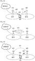
- FIGs. 4a to 4d schematically illustrate a process for configuring a wireless back haul link between an old BS and a new BS in a case that the new BS is newly deployed in a wireless communication system according to embodiments of the present disclosure.
- the wireless communication system includes a BS # 1 410, a BS # 2 420, and a Mobile Station (MS) 430.
- MS Mobile Station
- the MS 430 performs a scan operation for neighbor BSs. Upon detecting a preset Temporary code (Tcode), the MS 430 receives System Information (SI) from a BS which transmits the Tcode and stores the received SI (step 411). The Tcode is transmitted from only a newly deployed BS not a BS which has already been deployed. The MS 430 does not perform a random access operation with the BS which transmits the Tcode.
- Tcode System Information
- the SI includes location associated information of a related BS, and the location associated information includes a latitude, a longitude, an altitude, etc.
- the BS # 1 410 is an old BS
- the BS # 2 420 is a new BS that is newly deployed
- the MS 430 maintains a connection with the BS # 1 410.
- the MS 430 transmits a new BS information report message including the SI received from the BS # 2 420 to the BS # 1 410 (step 413).
- the BS # 1 410 After receiving the new BS information report message from the MS 430, the BS # 1 410 detects that there is the new BS using the Tcode around the BS # 1 410, so the BS # 1 410 should perform a Front-Haul Link Configuration Procedure (FLCP) with the new BS, e.g., the BS # 2 420.
- the BS # 1 410 starts the FLCP with the BS # 2 420.
- the BS # 1 410 transmits an FLCP start code transmission request message requesting to transmit an FLCP start request code indicating an FLCP start command to the BS # 2 420 (step 415).
- FLCP Front-Haul Link Configuration Procedure
- the BS # 1 410 may transmit the FLCP start code transmission request message to only the MS 430, and the number of MSs which transmit the FLCP start code transmission request message is determined without limitation according to a need of the BS # 1 410.
- the MS 430 After receiving the FLCP start code transmission request message, the MS 430 transmits the FLCP start code to the BS # 2 420 in order that the BS # 2 420 starts performing the FLCP with the BS # 1 410 (step 417).
- Steps 415 to 417 may be omitted, and the BS # 1 410 immediately starts performing the FLCP with the BS # 2 420 if the steps 415 to 417 are omitted.
- the BS # 1 410 and the BS # 2 420 perform an FLCP during a preset time at a preset timing point (step 419).
- the FLCP may include a procedure in which the BS # 1 410 transmits a reference symbol for a front haul link to the BS # 2 420 and receives the reference symbol from the BS # 2 420.
- the BS # 2 420 configures a wireless back haul with the BS # 1 410, updates a system operating parameter used for an air link, discards a Tcode which the BS # 2 420 has used, and uses a code for a normal air operation, i.e., a Normal code (Ncode) (step 421). If the BS # 2 420 uses the Ncode, the MS 430 may perform a normal operation with the BS 2 # 420 according to a need of the BS # 2 420 (step 423).
- Ncode Normal code
- FIG. 5 schematically illustrates a process for configuring a wireless back haul link between an old BS and a new BS illustrated in FIGs. 4a to 4d .
- a wireless communication system includes a BS # 1 410, a BS # 2 420, and an MS 430.
- the MS 430 performs a scan operation for neighbor BSs (step 511).
- the BS # 1 410 transmits an Ncode (step 513).
- the BS # 2 420 is newly deployed and powered on (step 515) and transmits a Tcode (step 517).
- the MS 430 detects an Ncode and a Tcode after performing the scan operation for the neighbor BSs (step 519) and SI for BSs which transmit the Ncode and the Tcode (step 521).
- the MS 430 detects SI for the BS # 1 410 which transmits the Ncode and SI for the BS # 2 420 which transmits the Tcode.
- the MS 430 transmits a random access code to the BS # 1 410 through a random access channel (RACH) (step 523), and performs a network entry procedure with the BS # 1 410 (step 525). After performing the network entry procedure with the BS # 1 410, the MS 430 transmits a new BS information report message to the BS # 1 410 (step 527). In FIG. 5 , after performing the network entry procedure, the MS 430 transmits the new BS information report message to the BS # 1 410, however, it will be understood by those of ordinary skill in the art that the new BS information report message may be transmitted to the BS # 1 410 during the network entry procedure.
- RACH random access channel
- the BS # 1 410 After receiving the new BS information report message from the MS 430, the BS # 1 410 detects that there is a new BS which is newly deployed around the BS # 1 410, so the BS # 1 410 determines to perform an FLCP with the new BS, i.e., the BS # 2 420 (step 529). After determining to perform the FLCP with the BS # 2 420, the BS # 1 410 transmits an FLCP start code transmission request message to the MS 430 and MSs which are connected to the BS # 1 410 (step 531). After receiving the FLCP start code transmission request message, the MS 430 transmits an FLCP start code to the BS # 2 420 (step 533).
- Steps 531 to 533 may be omitted, and the BS # 1 410 immediately starts performing the FLCP with the BS # 2 420 if the steps 531 to 533 are omitted.
- the BS # 1 410 and the BS # 2 420 perform an FLCP during a preset time at a preset timing point (step 535).
- the FLCP may include a procedure in which the BS # 1 410 transmits a reference symbol for a front haul link to the BS # 2 420 and receives the reference symbol from the BS # 2 420.
- a wireless back haul link is configured between the BS # 1 410 and the BS # 2 420 (step 537).
- the BS # 2 420 receives an Ncode from the BS # 1 410 through the wireless back haul link.
- the BS # 1 410 notifies the MS 430 that a Tcode used in the BS # 2 420 is discarded and an Ncode is used (step 539).
- the BS # 2 420 updates a system operating parameter used in an air link, discards the Tcode which the BS # 2 420 has used, and uses a code for a normal air operation, i.e., an Ncode (step 541).
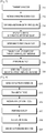
- FIG. 6 schematically illustrates an operation process of an MS 430 illustrated in FIG. 5 .
- the MS 430 performs a scan operation for neighbor BSs in step 611.
- the MS 430 detects an Ncode and a Tcode after performing the scan operation in step 613.
- the MS 430 detects SI for the BS # 1 410 which transmits the Ncode and SI for the BS # 2 420 which transmits the Tcode in step 615.
- the MS 430 transmits a random access code to the BS # 1 410 through a RACH in step 617.
- the MS 430 performs a network entry procedure with the BS # 1 410 in step 619.
- the MS 430 transmits a new BS information report message to the BS # 1 410 in step 621.
- the MS 430 receives an FLCP start code transmission request message from the BS # 1 410 in step 623.
- the MS 430 transmits an FLCP start code to the BS # 2 420 in step 625.
- the MS 430 is notified that the BS # 2 420 discards the Tcode and uses the Ncode by the BS # 1 410 in step 627.
- FIG. 7 schematically illustrates an operation process of a BS # 1 410 illustrated in FIG. 5 .
- the BS # 1 410 transmits an Ncode in step 711 and receives a random access code from an MS 430 in step 713.
- the BS # 1 410 performs a network entry procedure with the MS 430 in step 715.
- the BS # 1 410 receives a new BS information report message from the MS 430 in step 717.
- the BS # 1 410 determines to perform an FLCP with a BS # 2 420 in step 719.
- the BS # 1 410 transmits an FLCP start code transmission request message to the MS 430 and MSs which are connected to the BS # 1 410 in step 721.
- the BS # 1 410 performs an FLCP with the BS # 2 420 during a preset time at a preset timing point in step 723.
- the BS # 1 410 notifies the MS 430 that the Tcode used in the BS # 2 420 is discarded and an Ncode is used to in step 725.
- FIG. 8 schematically illustrates an operation process of a BS # 2 420 illustrated in FIG. 5 .
- the BS # 2 420 is newly deployed and powered on in step 811 and transmits a Tcode in step 813.
- the BS # 2 420 receives an FLCP start code from an MS 430 in step 815.
- the BS # 2 420 performs an FLCP with a BS # 1 410 in step 817.
- the BS # 2 420 receives an Ncode from the BS # 1 410 through a wireless back haul link in step 819.
- the BS # 2 420 discards the Tcode and uses the Ncode in step 821.
- FIG. 9 schematically illustrates an internal structure of an MS in a wireless communication system according to embodiments of the present disclosure.
- an MS (900) includes a transmitter 911, a controller 913, a receiver 915, and a storage unit 917.
- the controller 913 controls the overall operation of the MS 900.
- the controller 913 controls the MS 900 to perform an operation related to a wireless back haul link configuration operation between an old BS and a new BS.
- the operation related to the wireless back haul link configuration operation between the old BS and the new BS is performed in the manner described before with reference to FIGs. 4A to 6 .
- the storage unit 917 stores a program and data related to the operation of the MS 900.
- the transmitter 911 transmits signals and messages to the old BS and the new BS under a control of the controller 913.
- the transmitter 911 transmits the signals and the messages to the old BS and the new BS in the manner described before with reference to FIGs. 4a to 6 .
- the receiver 915 receives signals and messages from the old BS and the new BS under a control of the controller 913.
- the receiver 915 receives the signals and messages from the old BS and the new BS in the manner described before with reference to FIGs. 4a to 6 .
- transmitter 911 the controller 913, the receiver 915, and the storage unit 917 are shown in FIG. 9 as separate units for convenience of description. In other words, two or more of the transmitter 911, the controller 913, the receiver 915, and the storage unit 917 may be incorporated into a single unit.
- FIG. 10 schematically illustrates an internal structure of an old BS in a wireless communication system according to embodiments of the present disclosure.
- an old BS (1000) includes a transmitter 1011, a controller 1013, a receiver 1015, and a storage unit 1017.
- the controller 1013 controls the overall operation of the old BS 1000.
- the controller 1013 controls the old BS 1000 to perform an operation related to a wireless back haul link configuration operation between the old BS and a new BS.
- the operation related to the wireless back haul link configuration operation between the old BS and the new BS is performed in the manner described before with reference to FIGs. 4a to 4d , FIG. 5 , and FIG. 7 .
- the storage unit 1017 stores a program and data related to the operation of the old BS 1000.
- the transmitter 1011 transmits signals and messages to an MS and the new BS under a control of the controller 1013.
- the transmitter 1011 transmits the signals and the messages to the MS and the new BS in the manner described before with reference to FIGs. 4a to 4d , FIG. 5 , and FIG. 7 .
- the receiver 1015 receives signals and messages from the MS and the new BS under a control of the controller 1013.
- the receiver 1015 receives the signals and messages from the MS and the new BS in the manner described before with reference to FIGs. 4a to 4d , FIG. 5 , and FIG. 7 .
- transmitter 1011, the controller 1013, the receiver 1015, and the storage unit 1017 are shown in FIG. 10 as separate units for convenience of description. In other words, two or more of the transmitter 1011, the controller 1013, the receiver 1015, and the storage unit 1017 may be incorporated into a single unit.
- FIG. 11 schematically illustrates an internal structure of a new BS in a wireless communication system according to embodiments of the present disclosure.
- a new BS (1100) includes a transmitter 1111, a controller 1113, a receiver 1115, and a storage unit 1117.
- the controller 1113 controls the overall operation of the new BS 1100.
- the controller 1113 controls the new BS 1100 to perform an operation related to a wireless back haul link configuration operation between an old BS and the new BS.
- the operation related to the wireless back haul link configuration operation between the old BS and the new BS is performed in the manner described before with reference to FIGs. 4a to 4d , FIG. 5 , and FIG. 8 .
- the storage unit 1117 stores a program and data related to the operation of the new BS 1100.
- the transmitter 1111 transmits signals and messages to an MS and the old BS under a control of the controller 1113.
- the transmitter 1111 transmits the signals and the messages to the MS and the old BS in the manner described before with reference to FIGs. 4a to 4d , FIG. 5 , and FIG. 8 .
- the receiver 1115 receives signals and messages from the MS and the old BS under a control of the controller 1113.
- the receiver 1115 receives the signals and messages from the MS and the old BS in the manner described before with reference to FIGs. 4a to 4d , FIG. 5 , and FIG. 8 .
- transmitter 1111, the controller 1113, the receiver 1115, and the storage unit 1117 are shown in FIG. 11 as separate units for convenience of description. In other words, two or more of the transmitter 1111, the controller 1113, the receiver 1115, and the storage unit 1117 may be incorporated into a single unit.
Landscapes
- Engineering & Computer Science (AREA)
- Computer Networks & Wireless Communication (AREA)
- Signal Processing (AREA)
- Computer Security & Cryptography (AREA)
- Mobile Radio Communication Systems (AREA)
Claims (17)
- Procédé par une station mobile, MS, pour configurer une liaison terrestre sans fil entre des stations de base, BS, dans un système de communication sans fil, le procédé comprenant :recevoir (511) des informations de système, SI, pour chacune d'une première BS étant une BS déjà déployée qui transmet un premier code et une deuxième BS étant une BS récemment déployée qui transmet un deuxième code ;transmettre (527), à la première BS, un message incluant les SI pour la deuxième BS ;après avoir transmis le message, recevoir (531), à partir de la première BS, un message de demande pour transmettre un troisième code à la deuxième BS ; eten réponse au message de demande, transmettre (533), à la deuxième BS, le troisième code, le troisième code commandant à la deuxième BS de commencer à effectuer une procédure de configuration de liaison avec la première BS afin de configurer une liaison terrestre sans fil entre la première BS et la deuxième BS,où le premier code est un code transmis à partir d'une BS qui est déjà déployée, etoù le deuxième code est un code transmis à partir d'une BS qui est récemment déployée.
- Procédé de fonctionnement selon la revendication 1, où la procédure de configuration de liaison comprend une procédure où un symbole de référence pour une liaison est transmis à partir de la première BS à la deuxième BS et le symbole de référence est reçu par la première BS en provenance de la deuxième BS.
- Procédé selon la revendication 1, comprenant en outre :
détecter le premier code et le deuxième code en effectuant une opération de balayage pour des BS voisines. - Procédé selon la revendication 1, comprenant en outre :
effectuer une procédure d'entrée de réseau avec la première BS. - Procédé selon la revendication 1, où les SI du message comprennent des informations de localisation associées de la deuxième BS.
- Procédé selon la revendication 1, où le premier code est un code normal, Ncode, et le deuxième code est un code temporaire, Tcode.
- Procédé par une première station de base, BS, étant déjà déployée, pour configurer une liaison terrestre sans fil entre des stations de base, BS, dans un système de communication sans fil, le procédé comprenant :transmettre (513) un premier code;recevoir (527), à partir d'une station mobile, MS, un message incluant des informations de système, SI, pour une deuxième BS étant récemment déployée qui transmet un deuxième code ;après avoir reçu le message, transmettre (531), à la MS, un message de demande pour transmettre un troisième code à la deuxième BS, le troisième code commandant à la deuxième BS de commencer à effectuer une procédure de configuration de liaison avec la première BS afin de configurer une liaison terrestre sans fil entre la première BS et la deuxième BS ; eteffectuer (535) la procédure de configuration de liaison avec la deuxième BS,où le premier code est un code transmis à partir d'une BS qui est déjà déployée, etoù le deuxième code est un code transmis à partir d'une BS qui est récemment déployée.
- Procédé selon la revendication 7, où la procédure de configuration de liaison comprend une procédure où un symbole de référence pour une liaison est transmis à partir de la première BS à la deuxième BS et le symbole de référence est reçu par la première BS en provenance de la deuxième BS.
- Procédé selon la revendication 7, comprenant en outre :
effectuer une procédure d'entrée de réseau avec la MS. - Procédé selon la revendication 7, où les SI du message comprennent des informations associées à la localisation de la deuxième BS.
- Procédé selon la revendication 7, où le premier code est un code normal, Ncode, et le deuxième code est un code temporaire, Tcode.
- Procédé par une deuxième station de base, BS, étant récemment déployée pour configurer une liaison terrestre sans fil entre des stations de base, BS, dans un système de communication sans fil, le procédé comprenant :transmettre (517) un deuxième code;recevoir (533), à partir d'une station mobile, MS, un troisième code commandant à la deuxième BS de commencer à effectuer une procédure de configuration de liaison avec une première BS afin de configurer une liaison terrestre sans fil entre la première BS et la deuxième BS ; eteffectuer (535) la procédure de configuration de liaison avec la première BS qui transmet un premier code,où le premier code est un code transmis à partir d'une BS qui est déjà déployée, etoù le deuxième code est un code transmis à partir d'une BS qui est récemment déployée.
- Procédé selon la revendication 12, où la procédure de configuration de liaison comprend une procédure où un symbole de référence pour une liaison est transmis à partir de la première BS à la deuxième BS et le symbole de référence est reçu par la première BS en provenance de la deuxième BS.
- Procédé selon la revendication 12, où le premier code est un code normal, Ncode, et le deuxième code est un code temporaire, Tcode.
- Station mobile, MS, adaptée pour mettre en œuvre le procédé de fonctionnement de l'une des revendications 1 à 6.
- Première station de base, BS, adaptée pour mettre en œuvre le procédé de fonctionnement de l'une des revendications 7 à 11.
- Deuxième station de base, BS, adaptée pour mettre en œuvre le procédé de fonctionnement de l'une des revendications 12 à 14.
Applications Claiming Priority (2)
| Application Number | Priority Date | Filing Date | Title |
|---|---|---|---|
| KR1020120075330A KR102000567B1 (ko) | 2012-07-11 | 2012-07-11 | 무선 통신 시스템에서 무선 백홀 링크 형성 장치 및 방법 |
| PCT/KR2013/005989 WO2014010881A1 (fr) | 2012-07-11 | 2013-07-05 | Appareil et procédé pour configurer une liaison terrestre sans fil dans un système de communication sans fil |
Publications (3)
| Publication Number | Publication Date |
|---|---|
| EP2873286A1 EP2873286A1 (fr) | 2015-05-20 |
| EP2873286A4 EP2873286A4 (fr) | 2016-07-27 |
| EP2873286B1 true EP2873286B1 (fr) | 2020-12-30 |
Family
ID=49913951
Family Applications (1)
| Application Number | Title | Priority Date | Filing Date |
|---|---|---|---|
| EP13816498.3A Active EP2873286B1 (fr) | 2012-07-11 | 2013-07-05 | Appareil et procédé pour configurer une liaison terrestre sans fil dans un système de communication sans fil |
Country Status (4)
| Country | Link |
|---|---|
| US (1) | US9462577B2 (fr) |
| EP (1) | EP2873286B1 (fr) |
| KR (1) | KR102000567B1 (fr) |
| WO (1) | WO2014010881A1 (fr) |
Families Citing this family (1)
| Publication number | Priority date | Publication date | Assignee | Title |
|---|---|---|---|---|
| US10313168B2 (en) * | 2015-12-11 | 2019-06-04 | Lg Electronics Inc. | Method and user equipment for receiving downlink channel, and method and base station for transmitting downlink channel |
Family Cites Families (18)
| Publication number | Priority date | Publication date | Assignee | Title |
|---|---|---|---|---|
| EP1943777B1 (fr) * | 2005-10-31 | 2016-07-20 | LG Electronics Inc. | Procede de traitement d'informations de commande dans un systeme de communications mobile sans fil |
| EP2083595A1 (fr) * | 2008-01-23 | 2009-07-29 | Nokia Siemens Networks Oy | Procédé, dispositifs et système pour la configuration automatique et l'optimisation d'un réseau avec une signalisation réduite |
| EP2091298B1 (fr) | 2008-02-18 | 2012-05-16 | Alcatel Lucent | Transport de retour FDD intrabande |
| CN101568196B (zh) * | 2008-09-26 | 2011-11-02 | 华为技术有限公司 | 分配物理小区标识的方法和装置 |
| US8838090B2 (en) * | 2009-01-15 | 2014-09-16 | Telefonaktiebolaget Lm Ericsson (Publ) | Automatic detection and correction of physical cell identity conflicts |
| CN101848420B (zh) * | 2009-03-23 | 2014-01-01 | 中兴通讯股份有限公司 | 长期演进系统中回程链路的配置方法与装置 |
| US8825053B2 (en) * | 2009-05-11 | 2014-09-02 | Telefonaktiebolaget L M Ericsson (Publ) | Technique for instructing mobile stations communicating with cooperating access nodes |
| US20100291934A1 (en) * | 2009-05-14 | 2010-11-18 | Motorola, Inc. | Physical-layer cell identity assignment in a communication system |
| US20100291929A1 (en) * | 2009-05-14 | 2010-11-18 | Motorola, Inc. | Physical-layer cell identification in a communication system |
| US8200232B2 (en) * | 2009-08-12 | 2012-06-12 | Lg Electronics Inc. | Apparatus and method of cell reselection in wireless communication system |
| KR101577289B1 (ko) * | 2009-10-09 | 2015-12-14 | 삼성전자주식회사 | 무선통신시스템에서 물리적 셀 식별자를 할당하는 방법 및 장치 |
| KR101573940B1 (ko) * | 2009-11-06 | 2015-12-02 | 삼성전자주식회사 | 매크로 셀들과 소형 셀들을 포함하는 오버레이 네트워크에서 셀 운영 방법 및 시스템. |
| KR101724371B1 (ko) * | 2010-05-28 | 2017-04-10 | 삼성전자주식회사 | 셀들이 중첩되는 무선통신 시스템에서 이동성을 지원하기 위한 장치 및 방법 |
| WO2011161536A1 (fr) * | 2010-06-25 | 2011-12-29 | Nokia Corporation | Réaffectations d'identifiants de cellules réduites dans une zone localisée à bandes multiples |
| JP5516164B2 (ja) * | 2010-07-09 | 2014-06-11 | 富士通株式会社 | セル識別子の決定方法、無線基地局及び無線通信システム |
| WO2012042311A1 (fr) * | 2010-10-01 | 2012-04-05 | Nokia Corporation | Appareil et procédé de notification de relations de voisinage |
| WO2014054991A1 (fr) * | 2012-10-05 | 2014-04-10 | Telefonaktiebolaget L M Ericsson (Publ) | Procédé, appareil et programme informatique pour la gestion de liaisons terrestres |
| KR20150097457A (ko) * | 2012-12-12 | 2015-08-26 | 엘지전자 주식회사 | 백홀(backhaul) 링크 정보 전송 방법 및 장치 |
-
2012
- 2012-07-11 KR KR1020120075330A patent/KR102000567B1/ko active Active
-
2013
- 2013-07-05 WO PCT/KR2013/005989 patent/WO2014010881A1/fr not_active Ceased
- 2013-07-05 EP EP13816498.3A patent/EP2873286B1/fr active Active
- 2013-07-11 US US13/940,113 patent/US9462577B2/en active Active
Non-Patent Citations (1)
| Title |
|---|
| None * |
Also Published As
| Publication number | Publication date |
|---|---|
| KR102000567B1 (ko) | 2019-10-01 |
| EP2873286A1 (fr) | 2015-05-20 |
| US9462577B2 (en) | 2016-10-04 |
| WO2014010881A1 (fr) | 2014-01-16 |
| KR20140008138A (ko) | 2014-01-21 |
| EP2873286A4 (fr) | 2016-07-27 |
| US20140016584A1 (en) | 2014-01-16 |
Similar Documents
| Publication | Publication Date | Title |
|---|---|---|
| US20230142356A1 (en) | Radio communication system, base station and communication terminal | |
| EP3861812B1 (fr) | Communications en liaison latérale à rat multiples | |
| US10674380B2 (en) | On-demand system information for wireless terminal in connected state | |
| US10299180B2 (en) | Methods for controlling mobility of user equipment for performing V2X communication and apparatuses for performing the same | |
| US11184813B2 (en) | Method for performing cell reselection and device supporting the same | |
| CN107360561B (zh) | 改变连接状态的方法及其设备 | |
| EP3022971B1 (fr) | Procédé de prise en charge de la mobilité d'équipements d'utilisateur prenant en charge/utilisant des communications de dispositif à dispositif dans un système de communication mobile sans fil | |
| JP2022141780A (ja) | 移動体通信システム、通信端末および基地局 | |
| US11057832B2 (en) | Method and apparatus for transmitting and receiving a wake-up signal in a wireless communication system | |
| US20140126545A1 (en) | Handover control method, wireless communication terminal, and wireless communication device | |
| US20120309419A1 (en) | Method and apparatus for updating location information for a terminal | |
| CN108307543B (zh) | 用于改变ue连接状态的方法和装置 | |
| JP2017508406A (ja) | 無線通信システムでマシンタイプコミュニケーション端末のネットワーク選択、及びランダムアクセス方法及び装置 | |
| JP2016525850A (ja) | 移動通信システムでシステム情報とページングを受信する方法及び装置 | |
| CN106851614A (zh) | 在无线通信系统中执行成员资格验证或者接入控制的方法和装置 | |
| EP3292718B1 (fr) | Procédé et appareil permettant de transmettre des signaux de synchronisation dispositif à dispositif (d2d) | |
| CN112040523B (zh) | 信道测量方法、装置、终端及存储介质 | |
| EP2410809B1 (fr) | Procédé, dispositif et système conçus pour paramétrer une porteuse radio | |
| WO2019194727A1 (fr) | Systèmes et procédés pour ajuster des paramètres sur la base de l'état d'un réseau de bord | |
| CN110574429A (zh) | 切换控制方法和设备 | |
| US11109328B2 (en) | Method and apparatus for measuring downlink synchronization in wireless communication system | |
| CN104969600B (zh) | 省电方法、用户设备及基站 | |
| US9479921B2 (en) | Method and apparatus for performing closed subscriber group grouping in wireless communication system | |
| US10278101B2 (en) | Cell discovery method and apparatus | |
| US9462577B2 (en) | Apparatus and method for configuring wireless back haul link in wireless communication system |
Legal Events
| Date | Code | Title | Description |
|---|---|---|---|
| PUAI | Public reference made under article 153(3) epc to a published international application that has entered the european phase |
Free format text: ORIGINAL CODE: 0009012 |
|
| 17P | Request for examination filed |
Effective date: 20150112 |
|
| AK | Designated contracting states |
Kind code of ref document: A1 Designated state(s): AL AT BE BG CH CY CZ DE DK EE ES FI FR GB GR HR HU IE IS IT LI LT LU LV MC MK MT NL NO PL PT RO RS SE SI SK SM TR |
|
| AX | Request for extension of the european patent |
Extension state: BA ME |
|
| DAX | Request for extension of the european patent (deleted) | ||
| RIC1 | Information provided on ipc code assigned before grant |
Ipc: H04W 92/20 20090101ALN20160303BHEP Ipc: H04W 24/02 20090101AFI20160303BHEP |
|
| RA4 | Supplementary search report drawn up and despatched (corrected) |
Effective date: 20160628 |
|
| RIC1 | Information provided on ipc code assigned before grant |
Ipc: H04W 24/02 20090101AFI20160622BHEP Ipc: H04W 92/20 20090101ALN20160622BHEP |
|
| STAA | Information on the status of an ep patent application or granted ep patent |
Free format text: STATUS: EXAMINATION IS IN PROGRESS |
|
| 17Q | First examination report despatched |
Effective date: 20190228 |
|
| RIC1 | Information provided on ipc code assigned before grant |
Ipc: H04W 92/20 20090101ALN20191210BHEP Ipc: H04W 92/12 20090101ALN20191210BHEP Ipc: H04W 24/02 20090101AFI20191210BHEP Ipc: H04W 84/04 20090101ALN20191210BHEP |
|
| GRAP | Despatch of communication of intention to grant a patent |
Free format text: ORIGINAL CODE: EPIDOSNIGR1 |
|
| STAA | Information on the status of an ep patent application or granted ep patent |
Free format text: STATUS: GRANT OF PATENT IS INTENDED |
|
| RIC1 | Information provided on ipc code assigned before grant |
Ipc: H04W 92/12 20090101ALN20200107BHEP Ipc: H04W 84/04 20090101ALN20200107BHEP Ipc: H04W 24/02 20090101AFI20200107BHEP Ipc: H04W 92/20 20090101ALN20200107BHEP |
|
| INTG | Intention to grant announced |
Effective date: 20200127 |
|
| GRAJ | Information related to disapproval of communication of intention to grant by the applicant or resumption of examination proceedings by the epo deleted |
Free format text: ORIGINAL CODE: EPIDOSDIGR1 |
|
| STAA | Information on the status of an ep patent application or granted ep patent |
Free format text: STATUS: EXAMINATION IS IN PROGRESS |
|
| INTC | Intention to grant announced (deleted) | ||
| GRAP | Despatch of communication of intention to grant a patent |
Free format text: ORIGINAL CODE: EPIDOSNIGR1 |
|
| STAA | Information on the status of an ep patent application or granted ep patent |
Free format text: STATUS: GRANT OF PATENT IS INTENDED |
|
| RIC1 | Information provided on ipc code assigned before grant |
Ipc: H04W 92/12 20090101ALN20200604BHEP Ipc: H04W 24/02 20090101AFI20200604BHEP Ipc: H04W 84/04 20090101ALN20200604BHEP Ipc: H04W 92/20 20090101ALN20200604BHEP |
|
| INTG | Intention to grant announced |
Effective date: 20200706 |
|
| GRAJ | Information related to disapproval of communication of intention to grant by the applicant or resumption of examination proceedings by the epo deleted |
Free format text: ORIGINAL CODE: EPIDOSDIGR1 |
|
| REG | Reference to a national code |
Ref country code: DE Ref legal event code: R079 Ref document number: 602013075041 Country of ref document: DE Free format text: PREVIOUS MAIN CLASS: H04W0076020000 Ipc: H04W0024020000 |
|
| STAA | Information on the status of an ep patent application or granted ep patent |
Free format text: STATUS: EXAMINATION IS IN PROGRESS |
|
| GRAP | Despatch of communication of intention to grant a patent |
Free format text: ORIGINAL CODE: EPIDOSNIGR1 |
|
| STAA | Information on the status of an ep patent application or granted ep patent |
Free format text: STATUS: GRANT OF PATENT IS INTENDED |
|
| INTC | Intention to grant announced (deleted) | ||
| INTG | Intention to grant announced |
Effective date: 20201014 |
|
| RIC1 | Information provided on ipc code assigned before grant |
Ipc: H04W 92/20 20090101ALN20201002BHEP Ipc: H04W 84/04 20090101ALN20201002BHEP Ipc: H04W 92/12 20090101ALN20201002BHEP Ipc: H04W 24/02 20090101AFI20201002BHEP |
|
| GRAS | Grant fee paid |
Free format text: ORIGINAL CODE: EPIDOSNIGR3 |
|
| GRAA | (expected) grant |
Free format text: ORIGINAL CODE: 0009210 |
|
| STAA | Information on the status of an ep patent application or granted ep patent |
Free format text: STATUS: THE PATENT HAS BEEN GRANTED |
|
| AK | Designated contracting states |
Kind code of ref document: B1 Designated state(s): AL AT BE BG CH CY CZ DE DK EE ES FI FR GB GR HR HU IE IS IT LI LT LU LV MC MK MT NL NO PL PT RO RS SE SI SK SM TR |
|
| REG | Reference to a national code |
Ref country code: GB Ref legal event code: FG4D |
|
| REG | Reference to a national code |
Ref country code: AT Ref legal event code: REF Ref document number: 1351185 Country of ref document: AT Kind code of ref document: T Effective date: 20210115 |
|
| REG | Reference to a national code |
Ref country code: DE Ref legal event code: R096 Ref document number: 602013075041 Country of ref document: DE |
|
| REG | Reference to a national code |
Ref country code: IE Ref legal event code: FG4D |
|
| PG25 | Lapsed in a contracting state [announced via postgrant information from national office to epo] |
Ref country code: GR Free format text: LAPSE BECAUSE OF FAILURE TO SUBMIT A TRANSLATION OF THE DESCRIPTION OR TO PAY THE FEE WITHIN THE PRESCRIBED TIME-LIMIT Effective date: 20210331 Ref country code: RS Free format text: LAPSE BECAUSE OF FAILURE TO SUBMIT A TRANSLATION OF THE DESCRIPTION OR TO PAY THE FEE WITHIN THE PRESCRIBED TIME-LIMIT Effective date: 20201230 Ref country code: FI Free format text: LAPSE BECAUSE OF FAILURE TO SUBMIT A TRANSLATION OF THE DESCRIPTION OR TO PAY THE FEE WITHIN THE PRESCRIBED TIME-LIMIT Effective date: 20201230 Ref country code: NO Free format text: LAPSE BECAUSE OF FAILURE TO SUBMIT A TRANSLATION OF THE DESCRIPTION OR TO PAY THE FEE WITHIN THE PRESCRIBED TIME-LIMIT Effective date: 20210330 |
|
| REG | Reference to a national code |
Ref country code: AT Ref legal event code: MK05 Ref document number: 1351185 Country of ref document: AT Kind code of ref document: T Effective date: 20201230 |
|
| PG25 | Lapsed in a contracting state [announced via postgrant information from national office to epo] |
Ref country code: LV Free format text: LAPSE BECAUSE OF FAILURE TO SUBMIT A TRANSLATION OF THE DESCRIPTION OR TO PAY THE FEE WITHIN THE PRESCRIBED TIME-LIMIT Effective date: 20201230 Ref country code: SE Free format text: LAPSE BECAUSE OF FAILURE TO SUBMIT A TRANSLATION OF THE DESCRIPTION OR TO PAY THE FEE WITHIN THE PRESCRIBED TIME-LIMIT Effective date: 20201230 Ref country code: BG Free format text: LAPSE BECAUSE OF FAILURE TO SUBMIT A TRANSLATION OF THE DESCRIPTION OR TO PAY THE FEE WITHIN THE PRESCRIBED TIME-LIMIT Effective date: 20210330 |
|
| REG | Reference to a national code |
Ref country code: NL Ref legal event code: MP Effective date: 20201230 |
|
| PG25 | Lapsed in a contracting state [announced via postgrant information from national office to epo] |
Ref country code: HR Free format text: LAPSE BECAUSE OF FAILURE TO SUBMIT A TRANSLATION OF THE DESCRIPTION OR TO PAY THE FEE WITHIN THE PRESCRIBED TIME-LIMIT Effective date: 20201230 |
|
| REG | Reference to a national code |
Ref country code: LT Ref legal event code: MG9D |
|
| PG25 | Lapsed in a contracting state [announced via postgrant information from national office to epo] |
Ref country code: PT Free format text: LAPSE BECAUSE OF FAILURE TO SUBMIT A TRANSLATION OF THE DESCRIPTION OR TO PAY THE FEE WITHIN THE PRESCRIBED TIME-LIMIT Effective date: 20210430 Ref country code: RO Free format text: LAPSE BECAUSE OF FAILURE TO SUBMIT A TRANSLATION OF THE DESCRIPTION OR TO PAY THE FEE WITHIN THE PRESCRIBED TIME-LIMIT Effective date: 20201230 Ref country code: SK Free format text: LAPSE BECAUSE OF FAILURE TO SUBMIT A TRANSLATION OF THE DESCRIPTION OR TO PAY THE FEE WITHIN THE PRESCRIBED TIME-LIMIT Effective date: 20201230 Ref country code: LT Free format text: LAPSE BECAUSE OF FAILURE TO SUBMIT A TRANSLATION OF THE DESCRIPTION OR TO PAY THE FEE WITHIN THE PRESCRIBED TIME-LIMIT Effective date: 20201230 Ref country code: CZ Free format text: LAPSE BECAUSE OF FAILURE TO SUBMIT A TRANSLATION OF THE DESCRIPTION OR TO PAY THE FEE WITHIN THE PRESCRIBED TIME-LIMIT Effective date: 20201230 Ref country code: EE Free format text: LAPSE BECAUSE OF FAILURE TO SUBMIT A TRANSLATION OF THE DESCRIPTION OR TO PAY THE FEE WITHIN THE PRESCRIBED TIME-LIMIT Effective date: 20201230 Ref country code: NL Free format text: LAPSE BECAUSE OF FAILURE TO SUBMIT A TRANSLATION OF THE DESCRIPTION OR TO PAY THE FEE WITHIN THE PRESCRIBED TIME-LIMIT Effective date: 20201230 |
|
| PG25 | Lapsed in a contracting state [announced via postgrant information from national office to epo] |
Ref country code: AT Free format text: LAPSE BECAUSE OF FAILURE TO SUBMIT A TRANSLATION OF THE DESCRIPTION OR TO PAY THE FEE WITHIN THE PRESCRIBED TIME-LIMIT Effective date: 20201230 Ref country code: PL Free format text: LAPSE BECAUSE OF FAILURE TO SUBMIT A TRANSLATION OF THE DESCRIPTION OR TO PAY THE FEE WITHIN THE PRESCRIBED TIME-LIMIT Effective date: 20201230 |
|
| PG25 | Lapsed in a contracting state [announced via postgrant information from national office to epo] |
Ref country code: IS Free format text: LAPSE BECAUSE OF FAILURE TO SUBMIT A TRANSLATION OF THE DESCRIPTION OR TO PAY THE FEE WITHIN THE PRESCRIBED TIME-LIMIT Effective date: 20210430 |
|
| REG | Reference to a national code |
Ref country code: DE Ref legal event code: R097 Ref document number: 602013075041 Country of ref document: DE |
|
| PG25 | Lapsed in a contracting state [announced via postgrant information from national office to epo] |
Ref country code: AL Free format text: LAPSE BECAUSE OF FAILURE TO SUBMIT A TRANSLATION OF THE DESCRIPTION OR TO PAY THE FEE WITHIN THE PRESCRIBED TIME-LIMIT Effective date: 20201230 Ref country code: IT Free format text: LAPSE BECAUSE OF FAILURE TO SUBMIT A TRANSLATION OF THE DESCRIPTION OR TO PAY THE FEE WITHIN THE PRESCRIBED TIME-LIMIT Effective date: 20201230 |
|
| PLBE | No opposition filed within time limit |
Free format text: ORIGINAL CODE: 0009261 |
|
| STAA | Information on the status of an ep patent application or granted ep patent |
Free format text: STATUS: NO OPPOSITION FILED WITHIN TIME LIMIT |
|
| PG25 | Lapsed in a contracting state [announced via postgrant information from national office to epo] |
Ref country code: ES Free format text: LAPSE BECAUSE OF FAILURE TO SUBMIT A TRANSLATION OF THE DESCRIPTION OR TO PAY THE FEE WITHIN THE PRESCRIBED TIME-LIMIT Effective date: 20201230 Ref country code: DK Free format text: LAPSE BECAUSE OF FAILURE TO SUBMIT A TRANSLATION OF THE DESCRIPTION OR TO PAY THE FEE WITHIN THE PRESCRIBED TIME-LIMIT Effective date: 20201230 |
|
| 26N | No opposition filed |
Effective date: 20211001 |
|
| PG25 | Lapsed in a contracting state [announced via postgrant information from national office to epo] |
Ref country code: SI Free format text: LAPSE BECAUSE OF FAILURE TO SUBMIT A TRANSLATION OF THE DESCRIPTION OR TO PAY THE FEE WITHIN THE PRESCRIBED TIME-LIMIT Effective date: 20201230 |
|
| REG | Reference to a national code |
Ref country code: CH Ref legal event code: PL |
|
| PG25 | Lapsed in a contracting state [announced via postgrant information from national office to epo] |
Ref country code: MC Free format text: LAPSE BECAUSE OF FAILURE TO SUBMIT A TRANSLATION OF THE DESCRIPTION OR TO PAY THE FEE WITHIN THE PRESCRIBED TIME-LIMIT Effective date: 20201230 |
|
| REG | Reference to a national code |
Ref country code: BE Ref legal event code: MM Effective date: 20210731 |
|
| PG25 | Lapsed in a contracting state [announced via postgrant information from national office to epo] |
Ref country code: LI Free format text: LAPSE BECAUSE OF NON-PAYMENT OF DUE FEES Effective date: 20210731 Ref country code: CH Free format text: LAPSE BECAUSE OF NON-PAYMENT OF DUE FEES Effective date: 20210731 |
|
| PG25 | Lapsed in a contracting state [announced via postgrant information from national office to epo] |
Ref country code: IS Free format text: LAPSE BECAUSE OF FAILURE TO SUBMIT A TRANSLATION OF THE DESCRIPTION OR TO PAY THE FEE WITHIN THE PRESCRIBED TIME-LIMIT Effective date: 20210430 Ref country code: LU Free format text: LAPSE BECAUSE OF NON-PAYMENT OF DUE FEES Effective date: 20210705 |
|
| PG25 | Lapsed in a contracting state [announced via postgrant information from national office to epo] |
Ref country code: IE Free format text: LAPSE BECAUSE OF NON-PAYMENT OF DUE FEES Effective date: 20210705 Ref country code: BE Free format text: LAPSE BECAUSE OF NON-PAYMENT OF DUE FEES Effective date: 20210731 |
|
| PG25 | Lapsed in a contracting state [announced via postgrant information from national office to epo] |
Ref country code: HU Free format text: LAPSE BECAUSE OF FAILURE TO SUBMIT A TRANSLATION OF THE DESCRIPTION OR TO PAY THE FEE WITHIN THE PRESCRIBED TIME-LIMIT; INVALID AB INITIO Effective date: 20130705 |
|
| PG25 | Lapsed in a contracting state [announced via postgrant information from national office to epo] |
Ref country code: CY Free format text: LAPSE BECAUSE OF FAILURE TO SUBMIT A TRANSLATION OF THE DESCRIPTION OR TO PAY THE FEE WITHIN THE PRESCRIBED TIME-LIMIT Effective date: 20201230 |
|
| PG25 | Lapsed in a contracting state [announced via postgrant information from national office to epo] |
Ref country code: SM Free format text: LAPSE BECAUSE OF FAILURE TO SUBMIT A TRANSLATION OF THE DESCRIPTION OR TO PAY THE FEE WITHIN THE PRESCRIBED TIME-LIMIT Effective date: 20201230 |
|
| PG25 | Lapsed in a contracting state [announced via postgrant information from national office to epo] |
Ref country code: MK Free format text: LAPSE BECAUSE OF FAILURE TO SUBMIT A TRANSLATION OF THE DESCRIPTION OR TO PAY THE FEE WITHIN THE PRESCRIBED TIME-LIMIT Effective date: 20201230 |
|
| PG25 | Lapsed in a contracting state [announced via postgrant information from national office to epo] |
Ref country code: TR Free format text: LAPSE BECAUSE OF FAILURE TO SUBMIT A TRANSLATION OF THE DESCRIPTION OR TO PAY THE FEE WITHIN THE PRESCRIBED TIME-LIMIT Effective date: 20201230 |
|
| PG25 | Lapsed in a contracting state [announced via postgrant information from national office to epo] |
Ref country code: MT Free format text: LAPSE BECAUSE OF FAILURE TO SUBMIT A TRANSLATION OF THE DESCRIPTION OR TO PAY THE FEE WITHIN THE PRESCRIBED TIME-LIMIT Effective date: 20201230 |
|
| PGFP | Annual fee paid to national office [announced via postgrant information from national office to epo] |
Ref country code: GB Payment date: 20250624 Year of fee payment: 13 |
|
| PGFP | Annual fee paid to national office [announced via postgrant information from national office to epo] |
Ref country code: FR Payment date: 20250624 Year of fee payment: 13 |
|
| PGFP | Annual fee paid to national office [announced via postgrant information from national office to epo] |
Ref country code: DE Payment date: 20250624 Year of fee payment: 13 |