EP2873509A2 - Machine à plateaux tournants à entraînement direct - Google Patents
Machine à plateaux tournants à entraînement direct Download PDFInfo
- Publication number
- EP2873509A2 EP2873509A2 EP20140177774 EP14177774A EP2873509A2 EP 2873509 A2 EP2873509 A2 EP 2873509A2 EP 20140177774 EP20140177774 EP 20140177774 EP 14177774 A EP14177774 A EP 14177774A EP 2873509 A2 EP2873509 A2 EP 2873509A2
- Authority
- EP
- European Patent Office
- Prior art keywords
- rotary machine
- bearing
- stator
- machine
- rotating part
- Prior art date
- Legal status (The legal status is an assumption and is not a legal conclusion. Google has not performed a legal analysis and makes no representation as to the accuracy of the status listed.)
- Withdrawn
Links
- 238000001816 cooling Methods 0.000 claims description 29
- 239000000314 lubricant Substances 0.000 claims description 9
- 239000007788 liquid Substances 0.000 claims description 7
- 239000002826 coolant Substances 0.000 claims description 6
- 238000010017 direct printing Methods 0.000 claims description 6
- 238000002372 labelling Methods 0.000 claims description 6
- 238000000071 blow moulding Methods 0.000 claims description 4
- 239000000945 filler Substances 0.000 claims description 3
- 238000007689 inspection Methods 0.000 claims description 2
- 238000010276 construction Methods 0.000 description 6
- 238000013461 design Methods 0.000 description 6
- 230000008901 benefit Effects 0.000 description 5
- 230000007613 environmental effect Effects 0.000 description 5
- 238000005259 measurement Methods 0.000 description 5
- 230000033001 locomotion Effects 0.000 description 4
- 238000012423 maintenance Methods 0.000 description 4
- 230000007257 malfunction Effects 0.000 description 4
- 238000007639 printing Methods 0.000 description 4
- 239000003570 air Substances 0.000 description 3
- 230000005540 biological transmission Effects 0.000 description 3
- 238000003860 storage Methods 0.000 description 3
- 230000000712 assembly Effects 0.000 description 2
- 238000000429 assembly Methods 0.000 description 2
- 230000006378 damage Effects 0.000 description 2
- 238000011161 development Methods 0.000 description 2
- 230000018109 developmental process Effects 0.000 description 2
- 230000000694 effects Effects 0.000 description 2
- 230000005611 electricity Effects 0.000 description 2
- 230000005672 electromagnetic field Effects 0.000 description 2
- 230000004907 flux Effects 0.000 description 2
- 238000004519 manufacturing process Methods 0.000 description 2
- 238000000034 method Methods 0.000 description 2
- 230000008439 repair process Effects 0.000 description 2
- 238000005299 abrasion Methods 0.000 description 1
- XAGFODPZIPBFFR-UHFFFAOYSA-N aluminium Chemical compound [Al] XAGFODPZIPBFFR-UHFFFAOYSA-N 0.000 description 1
- 229910052782 aluminium Inorganic materials 0.000 description 1
- 239000012080 ambient air Substances 0.000 description 1
- 235000013361 beverage Nutrition 0.000 description 1
- 230000008859 change Effects 0.000 description 1
- 238000006243 chemical reaction Methods 0.000 description 1
- 238000004140 cleaning Methods 0.000 description 1
- 239000004020 conductor Substances 0.000 description 1
- 230000007423 decrease Effects 0.000 description 1
- 230000001419 dependent effect Effects 0.000 description 1
- 238000001746 injection moulding Methods 0.000 description 1
- 230000003993 interaction Effects 0.000 description 1
- 230000001050 lubricating effect Effects 0.000 description 1
- 238000005461 lubrication Methods 0.000 description 1
- 239000000463 material Substances 0.000 description 1
- 230000008569 process Effects 0.000 description 1
- 238000012545 processing Methods 0.000 description 1
- 230000005855 radiation Effects 0.000 description 1
- 230000009467 reduction Effects 0.000 description 1
- 238000005096 rolling process Methods 0.000 description 1
- 239000000243 solution Substances 0.000 description 1
- 238000005507 spraying Methods 0.000 description 1
- 238000013519 translation Methods 0.000 description 1
- 230000014616 translation Effects 0.000 description 1
- XLYOFNOQVPJJNP-UHFFFAOYSA-N water Substances O XLYOFNOQVPJJNP-UHFFFAOYSA-N 0.000 description 1
Images


Classifications
-
- B—PERFORMING OPERATIONS; TRANSPORTING
- B67—OPENING, CLOSING OR CLEANING BOTTLES, JARS OR SIMILAR CONTAINERS; LIQUID HANDLING
- B67B—APPLYING CLOSURE MEMBERS TO BOTTLES JARS, OR SIMILAR CONTAINERS; OPENING CLOSED CONTAINERS
- B67B1/00—Closing bottles, jars or similar containers by applying stoppers
- B67B1/08—Securing stoppers, e.g. swing stoppers, which are held in position by associated pressure-applying means coacting with the bottle neck
-
- H—ELECTRICITY
- H02—GENERATION; CONVERSION OR DISTRIBUTION OF ELECTRIC POWER
- H02K—DYNAMO-ELECTRIC MACHINES
- H02K7/00—Arrangements for handling mechanical energy structurally associated with dynamo-electric machines, e.g. structural association with mechanical driving motors or auxiliary dynamo-electric machines
- H02K7/10—Structural association with clutches, brakes, gears, pulleys or mechanical starters
- H02K7/1004—Structural association with clutches, brakes, gears, pulleys or mechanical starters with pulleys
- H02K7/1012—Machine arranged inside the pulley
- H02K7/1016—Machine of the outer rotor type
-
- H—ELECTRICITY
- H02—GENERATION; CONVERSION OR DISTRIBUTION OF ELECTRIC POWER
- H02K—DYNAMO-ELECTRIC MACHINES
- H02K7/00—Arrangements for handling mechanical energy structurally associated with dynamo-electric machines, e.g. structural association with mechanical driving motors or auxiliary dynamo-electric machines
- H02K7/14—Structural association with mechanical loads, e.g. with hand-held machine tools or fans
-
- B—PERFORMING OPERATIONS; TRANSPORTING
- B65—CONVEYING; PACKING; STORING; HANDLING THIN OR FILAMENTARY MATERIAL
- B65G—TRANSPORT OR STORAGE DEVICES, e.g. CONVEYORS FOR LOADING OR TIPPING, SHOP CONVEYOR SYSTEMS OR PNEUMATIC TUBE CONVEYORS
- B65G23/00—Driving gear for endless conveyors; Belt- or chain-tensioning arrangements
-
- H—ELECTRICITY
- H02—GENERATION; CONVERSION OR DISTRIBUTION OF ELECTRIC POWER
- H02K—DYNAMO-ELECTRIC MACHINES
- H02K11/00—Structural association of dynamo-electric machines with electric components or with devices for shielding, monitoring or protection
- H02K11/20—Structural association of dynamo-electric machines with electric components or with devices for shielding, monitoring or protection for measuring, monitoring, testing, protecting or switching
- H02K11/21—Devices for sensing speed or position, or actuated thereby
-
- H—ELECTRICITY
- H02—GENERATION; CONVERSION OR DISTRIBUTION OF ELECTRIC POWER
- H02K—DYNAMO-ELECTRIC MACHINES
- H02K26/00—Machines adapted to function as torque motors, i.e. to exert a torque when stalled
-
- H—ELECTRICITY
- H02—GENERATION; CONVERSION OR DISTRIBUTION OF ELECTRIC POWER
- H02K—DYNAMO-ELECTRIC MACHINES
- H02K3/00—Details of windings
- H02K3/04—Windings characterised by the conductor shape, form or construction, e.g. with bar conductors
-
- H—ELECTRICITY
- H02—GENERATION; CONVERSION OR DISTRIBUTION OF ELECTRIC POWER
- H02K—DYNAMO-ELECTRIC MACHINES
- H02K7/00—Arrangements for handling mechanical energy structurally associated with dynamo-electric machines, e.g. structural association with mechanical driving motors or auxiliary dynamo-electric machines
- H02K7/08—Structural association with bearings
-
- H—ELECTRICITY
- H02—GENERATION; CONVERSION OR DISTRIBUTION OF ELECTRIC POWER
- H02K—DYNAMO-ELECTRIC MACHINES
- H02K9/00—Arrangements for cooling or ventilating
- H02K9/08—Arrangements for cooling or ventilating by gaseous cooling medium circulating wholly within the machine casing
-
- B—PERFORMING OPERATIONS; TRANSPORTING
- B29—WORKING OF PLASTICS; WORKING OF SUBSTANCES IN A PLASTIC STATE IN GENERAL
- B29C—SHAPING OR JOINING OF PLASTICS; SHAPING OF MATERIAL IN A PLASTIC STATE, NOT OTHERWISE PROVIDED FOR; AFTER-TREATMENT OF THE SHAPED PRODUCTS, e.g. REPAIRING
- B29C49/00—Blow-moulding, i.e. blowing a preform or parison to a desired shape within a mould; Apparatus therefor
- B29C49/28—Blow-moulding apparatus
- B29C49/30—Blow-moulding apparatus having movable moulds or mould parts
- B29C49/36—Blow-moulding apparatus having movable moulds or mould parts rotatable about one axis
Definitions
- the present invention relates to a rotary machine, in particular the drive of the rotary machine.
- Rotary machines for example in the beverage processing industry, are well known.
- stretch blow molding machines or labeling machines and direct printing machines for treating containers which are designed as rotary machines and can thus work continuously and / or clockingly.
- the connection between rotary and the rotating part of these rotary machines are often realized via ball slewing. These have teeth, so that a connection, for example via a pinion can be made with a servo motor, which then drives the corresponding carousel.
- a connection for example via a pinion can be made with a servo motor, which then drives the corresponding carousel.
- a servo motor which then drives the corresponding carousel.
- it can lead to misalignments, especially due to gear play. This makes it difficult to meet the high accuracy requirements, especially in the labeling and printing of containers.
- the lubrication of the bearings in which the carousel is performed, and the gears proves to be very expensive and it is a very large space required to accommodate the entire drive system.
- the rotary machine according to the invention is characterized in that the rotating part and the fixed part are formed so that they together form the drive of the machine, wherein the rotating part forms the rotor and the fixed part forms the stator of an electric motor.
- a drive of the rotating part of the container treatment machine or rotary machine can be done in a technically simple manner and on maintenance-intensive gearboxes are dispensed with.
- the rotation can be set much more precise, which significantly improves the treatment results achieved.
- the stator is part of the machine supporting structure. According to a further embodiment, it can therefore be provided that the stator is formed further inwards, towards the central axis of the rotary machine and thus provided separately from the machine supporting structure.
- the supporting structure in this embodiment is then preferably radially outward, i. so arranged radially away from the center axis of the rotary machine as the stator.
- This construction supporting the machine can likewise be designed as a hollow cylinder or else designed as individual segments / supports arranged around the central axis of the rotary machine. Since the stator no longer assumes any supporting function here, a lighter removal, for example, can take place from above through the rotor and, in particular, the entire construction of the stator can be made lighter. It is particularly advantageous here if the stator is formed in several pieces, so that removal of the individual parts of the stator can be accomplished without much effort.
- the machine supporting structure is formed farther inwards towards the center axis of the rotary machine and thus provided separately from the stator.
- the stator is then preferably arranged in an unchanged position in this embodiment.
- the stator in this embodiment is then preferably radially outward, i. so arranged radially away from the center axis of the rotary machine as the machine supporting structure.
- the machine supporting structure may also be formed as a hollow cylinder or be designed as arranged around the center axis of the rotary machine individual segments / supports. Since the stator no longer assumes any supporting function here, a lighter removal, for example, can take place from above through the rotor and, in particular, the entire construction of the stator can be made lighter. It is particularly advantageous here if the stator is formed in several pieces, so that removal of the individual parts of the stator can be accomplished without much effort.
- the fixed part and the rotating part each comprise a cylindrically shaped area, wherein the cylindrical areas are formed so that they engage, and wherein the fixed part in the cylindrical area comprises at least one electromagnet and the rotating part in the cylindrical area at least one Magnet includes.
- the rotating part may be connected to the fixed part via a bearing, wherein the bearing is or comprises either a thin-ring bearing, a wire bearing, a preferably backlash-biased bearing, a bearing ring-free four-point torque bearing element.
- the bearing is or comprises either a thin-ring bearing, a wire bearing, a preferably backlash-biased bearing, a bearing ring-free four-point torque bearing element.
- the power supply to supply the electromagnet in the fixed part is guided to the electromagnet.
- the power supply protected against environmental influences, such as moisture, are guided by the rotary machine.
- the electromagnet is designed as a coil extending around the entire circumference of the stator.
- the coil is possibly a very large component, the replacement in the event of a malfunction proves to be relatively simple since the entire coil can be removed as one component.
- the electromagnet consists of at least one sub-segment, wherein a plurality of individual sub-segments can be formed over the entire circumference of the stator.
- the electrical connection of the individual segments can be realized for example by means of plug connector. Replacement in the event of a malfunction is relatively simple, since individual segments can be removed radially outwards.
- the rotary machine is characterized in that the rotating member comprises a cover extending at least over the magnet and at least partially insulating the cylindrical portions from the environment. This ensures that both the bearing and the electrical components are protected against environmental influences and that maintenance and cleaning work has to be carried out less frequently.
- a rotary encoder is provided, which is suitable for measuring the rotational speed and / or rotational speed and / or rotational position on the rotating part of the rotary machine. Because this encoder is the speed or rotational speed of the rotating Part can measure directly results in a more accurate speed determination and position determination, compared with known from the prior art measuring methods.
- a lubricating line is provided, which is connected to the bearing and is suitable for supplying lubricant to the bearing. So it can be ensured that the wear of the bearing is minimized.
- the cylindrical areas are formed as hollow cylinder jackets. In this way, an economical and significantly lighter construction of the rotary machines can be realized.
- a cooling unit is provided which is suitable for cooling the bearing and / or the electromagnet and / or the magnet by heat exchange with a cooling medium. If both the stator and the rotor are permanently cooled and the bearing is also cooled, unwanted malfunctions or wear or destruction of the individual components due to the constant temperature can be avoided.
- the cooling medium is a gas or a liquid.
- gas cooling is inexpensive and less susceptible to interference
- liquid cooling offers the advantage that more effective cooling can be realized due to the high heat capacity of the liquid and the better heat exchange.
- Cooling fins / webs so geometries with a large surface and the most thermally conductive material, which is cooled by convection and / or radiation.
- the rotary machine may be characterized in that the cylindrical portion of the rotating part comprises a circular disc on which at least one magnet is arranged.
- the entire size of the cylindrical portion of the rotating portion can be reduced, and the rotating portion can be fitted, for example, on the standing portion.
- the necessary rotatable mounting of the rotor can be realized via a corresponding bearing.
- the rotating part is designed as engaging in the fixed part or the fixed part is designed as engaging in the rotating part.
- the rotary machine may be a labeling machine, a stretch blow molding machine, a direct printing machine or a filler. These can be machines that both produce containers (preform spraying machine) and handle containers.
- the design of the rotary machine as one of these machines allows the utilization of the above-described advantages in the corresponding manufacturing and treatment steps for containers.
- Fig. 1a 1 shows a rotary machine 100 according to the invention.
- This comprises a stationary part 101 and a rotating part 102.
- container treatment stations or container clamping stations or elements for fixing the containers or container transport elements are arranged on the rotating part 102.
- the rotating part comprises a plurality of container treatment stations or container clamping stations. These can include, for example, individual turntables and printing modules assigned to them.
- On the fixed part 101 of the rotary machine other components may be arranged, such as ink reservoir, labeling or printing units or the like, depending on the design of the rotary machine.
- a wide variety of embodiments are already known, which may depend on the type of container treatment machine.
- the fixed part 101 and the rotating part 102 are connected to each other via a bearing, so that the rotating part 102 rests on the fixed part 101.
- a corresponding drive unit then the rotating part 102 can be rotated relative to the fixed part 101 in rotation.
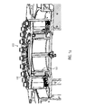
- Fig. 1b shows an inventive embodiment of the fixed part 101 and the rotating part 102.
- the fixed part of the rotary machine the stator and the rotating part 102 of the rotary machine form the rotor of an electric motor.
- 101 electromagnets are arranged in the stator, which can generate by appropriate control electromagnetic alternating fields.
- Magnets are provided in the rotating part 102. Due to the electromagnetic interaction between the electromagnets and the magnets in the stator or rotor 102, the rotor 102 is then rotated relative to the stator 101 in rotation.
- the electromagnets or magnets in the stator and rotor can in principle be arbitrarily arranged. Accordingly, they do not have to be arranged directly adjacent to each other.
- the bearing 103 may be formed manifold. It is advantageous if the bearing is designed as a thin-ring bearing.
- a wire bearing or a preferably backlash-free preloaded bearing can be used.
- a bearing ring-free four-point torque bearing element is particularly advantageous.
- the inner ring and the outer ring of the bearing are separated by rolling bodies, in particular balls.
- rolling bodies in particular balls.
- four separate rails are provided in which they can be performed. Due to the ball bearing, the use of such a four-point-moment bearing element is particularly preferred because it comes to less wear here.
- both the stator 101 and the rotor 102 are formed as at least partially cylindrical components or as components which comprise a cylindrical portion. These summarize in one embodiment directly into each other, as in Fig. 1b is shown. Thus, an additional fixation takes place beyond the bearing 103, since the outer surface of the stator 101 and the inner surface of the rotor 102 (the corresponding lateral surfaces) here ensure a limitation of the range of motion. This embodiment can furthermore be advantageously used to protect the sensitive components of this direct drive (in particular the electromagnets) from harmful environmental influences, such as moisture.
- the rotor 102 of the in Fig. 1 illustrated embodiment the stator 101 engages, acts here as a corresponding shield. It can also be provided that the rotor 102 is formed as engaging in the stator 101.
- a rotary encoder 104 is arranged, which may be connected to the rotor 102 or at least formed so that it can measure the rotational movement of the rotor 102.
- the rotational speed and / or the rotational position of the rotor 102 can be measured directly at any time by the rotary encoder 104, without an indirect measurement via the rotational speed measurement of an additionally connected motor or via a speed measurement of a transmission.
- the direct measurement with the rotary encoder 104 therefore allows a very precise measurement of the movement parameters of the rotor 102.
- the lubricant supply 105 and / or the power supply 107 are also guided through the inner region of the stator 101 and so can supply the electromagnets of the stator 101 with electricity and the bearing can be supplied with lubricant.
- the stator 101 is formed as a hollow cylinder or as a hollow cylinder jacket and is as thin-walled, but without significantly affecting the carrying capacity of the stator 101. The larger the free space of the stator 101, the more sensitive components can be accommodated here. Since this area is protected by the rotor 102 from environmental influences, so a space-saving storage of sensitive components can be guaranteed.
- the stator 101 is part of the machine supporting structure. Problems on the stator, such as malfunctions of the electromagnets thus require a complete conversion of the machine to change or repair corresponding components. According to one embodiment, it can therefore be provided that the stator 101 is formed farther inwards, towards the rotary encoder 104 or the center axis of the rotary machine, and thus provided separately from the machine supporting structure.
- the supporting structure in this embodiment is then preferably at an unchanged location (that is, where in Fig. 1a and Fig. 1b the stator is shown).
- the construction supporting the machine is formed further inwards towards the rotary encoder 104 or the center axis of the rotary machine and thus provided separately from the stator 101.
- the stator 101 is then in this embodiment preferably at an unchanged location (see. Fig. 1a and 1b ) arranged. Since the stator 101 then assumes no supporting function in both variants, a lighter removal, for example, can take place from above through the rotor 102 and, in particular, the entire construction of the stator can be made lighter. It is particularly advantageous here, if the stator 101 is formed in several pieces, so that a removal of the individual parts of the stator 101 can be accomplished without much effort.
- the stator 101 can also be realized outside the rotor 102 by the electromagnets are installed, for example, in the stator 102 surrounding pylons, which are connected to the fixed part of the rotary machine (in particular a stand table).
- the rotor 102 is then disposed within this stator, whereby the individual components of the stator are easier to reach.
- This embodiment also allows a simple adjustment of the performance of the device, since possibly more pylons can be grown with electromagnets.
- 4 pylons may be provided, which are arranged symmetrically in a concentric region around the rotor 102.
- 8, 12 or 16 pylons may be provided here or any other number of pylons.
- the rotating part 102 is identified here as a whole with the rotor and the fixed part 101 is identified with the stator, a two-part or multi-part design can also be realized.
- the rotating part 102 may include a rotor portion 102a and a bearing portion 102b in which, for example, a part of the guide for the bearing 103 is disposed. These may be formed as separate but interconnected components.
- the rotor 102a may be provided as a ring, which is connected to the bearing portion 102b and the remaining part of the rotating part 102, for example by screwing.
- the fixed part 101 can also be designed in two parts or in several parts, wherein the stator 101a can be provided as a separate component, which can be connected to the bearing region 101b of the stationary part 101 corresponding to the bearing region 102b.
- the two-part design of the fixed area further has the advantage that the power supply 107 and the lubricant supply 105 can be guided into the respective areas. For example, during maintenance work to remove the bearing, it is not necessary to remove the entire power supply to the solenoids and vice versa. It is then sufficient to replace the lubricant supply 105, if necessary, with an exchange of the bearing or corresponding maintenance work.
- the stator 101 is associated with a cooling system 106, which can initiate a cooling medium in the stator 101 or at least a cooling effect such that the electromagnets of the stator 101, the magnets of the rotor 102 and the bearing 103 cooled become.
- the cooling system is designed so that a cooling of these three modules can be done simultaneously.
- the Magnets and electromagnets are arranged as close to the camp.
- the cooling system can also consist of 3 individual cooling systems (solenoid cooling, magnetic cooling, storage cooling), which are then preferably formed separately and can be controlled.
- the cooling system can in principle be of any desired design, but gas cooling or liquid cooling, for example with water, is suitable.
- appropriate pipes and channels can be pulled through the stator 101, which distribute the cooling medium in this.
- liquid cooling must meet special requirements when used to cool electronic components, it can be provided that, when liquid cooling is used, only indirect heat exchange occurs across a dividing wall (eg a thin wall of aluminum or similar material).
- a heat exchange between the electromagnet and the cooling unit 106 can be accomplished while reducing the risk of damage and short circuits, preferably avoided.
- a further cooling unit or the same cooling unit can be provided to also cool the interior of the stator 101, in which, as already mentioned, sensitive assemblies, such as control units or electronics, can be arranged.
- lubricant can be permanently supplied to the bearing 103 via a correspondingly provided line, so that the resulting abrasion and friction effects are minimized as much as possible, which increases the energy efficiency of the rotary machine.
- the stator 101 comprises one or more electromagnets 210, for example, along the periphery of the in Fig. 1 illustrated cylindrical portion of the stator 101 are arranged.
- a large number of individual and individually activatable electromagnets 210 can be distributed over the entire circumference of the stator 101.
- a coil is used which extends around the entire circumference or a region of the stator.
- the magnets 220 of the rotor 102 are directly adjacent to the electromagnet 210. Since the field strength of electromagnetic fields decreases with increasing distance, this arrangement of the magnets and electromagnets is particularly preferred since hardly any losses occur when the distance between the electromagnet and magnet is only a few millimeters.
- the Fig. 2 illustrated embodiment is also characterized in that the electromagnet 210 of the stator 101 and the magnets 220 of the rotor 102 of the bearing 103 are directly adjacent. Furthermore, the power supply 230 is shown, the the electromagnet 210 is powered. If only one continuous coil is provided, which is fastened to the stator 101, then a single current supply 230 is sufficient.
- the region 221 between the magnets 220 and the electromagnet 210 is preferably filled with air. Since the individual components stator 101 and rotor 102 need not be hermetically separated from the environment, this air may be the normal ambient air. However, it may also be advantageous if, when using gas cooling, the cooling device is suitable for introducing air into this intermediate region for cooling. Thus, the surface of the magnets and electromagnets can be cooled on this side.
- Fig. 3 shows a further embodiment in which the stator 101 is not completely covered by the rotor 102 and in which the rotor 102 is formed as a circular disk.
- the electromagnets 310 of the stator 101 are not arranged laterally but on the upper edge of the stator 101.
- the magnets 320 of the rotor 102 are arranged on the stator 101 facing side.
- an annular seal 350 can be provided to the outside, which shields the inner region of the stator 101 from the environment.
- a cylinder jacket-shaped extension of the rotor 102 may be provided, which engages around the stator 101 from the outside. Such a contactless shielding is generally preferred.
- the electromagnets in the stator 101 form alternating fields with a maximum flux density of 1T, so that the Rotor 102 can be rotated.
- a plurality of assemblies are arranged on the stator or a fixed table or additional component, so that the rotor 102 can be performed as easily as possible, which reduces the amount of energy required to drive.
- the drive for rotary machines presented here can in principle be used for all container treatment machines, in particular also for preform injection molding machines, with which plastic preforms can be produced for the production of containers, and stretch blow molding machines, which are e.g. can process these preforms into bottles. Furthermore, a corresponding drive in fillers, cappers, rinsers and inspection machines for empty and / or full bottles can be used. Particularly advantageous is the use of these drives for labeling and Be perspectiveserverteil- and / or alignment and direct printing machines, since the direct drive used allows a very precise control of the movement of the rotor. This is particularly advantageous in direct printing of containers, since a very precise alignment of the container in relation to the individual printing modules is necessary here. With the direct drive according to the invention, a corresponding positioning to a few millimeters to a few hundredths or tenths of a millimeter can be done accurately, which greatly improves the quality of the printed images applied.
Landscapes
- Engineering & Computer Science (AREA)
- Power Engineering (AREA)
- Microelectronics & Electronic Packaging (AREA)
- Mechanical Engineering (AREA)
- Connection Of Motors, Electrical Generators, Mechanical Devices, And The Like (AREA)
- Food-Manufacturing Devices (AREA)
- Crushing And Pulverization Processes (AREA)
Applications Claiming Priority (1)
| Application Number | Priority Date | Filing Date | Title |
|---|---|---|---|
| DE201310218438 DE102013218438A1 (de) | 2013-09-13 | 2013-09-13 | Rundläufermaschine mit Direktantrieb |
Publications (2)
| Publication Number | Publication Date |
|---|---|
| EP2873509A2 true EP2873509A2 (fr) | 2015-05-20 |
| EP2873509A3 EP2873509A3 (fr) | 2016-07-27 |
Family
ID=51220419
Family Applications (1)
| Application Number | Title | Priority Date | Filing Date |
|---|---|---|---|
| EP14177774.8A Withdrawn EP2873509A3 (fr) | 2013-09-13 | 2014-07-21 | Machine à plateaux tournants à entraînement direct |
Country Status (4)
| Country | Link |
|---|---|
| US (1) | US20150076939A1 (fr) |
| EP (1) | EP2873509A3 (fr) |
| CN (1) | CN104444981A (fr) |
| DE (1) | DE102013218438A1 (fr) |
Cited By (1)
| Publication number | Priority date | Publication date | Assignee | Title |
|---|---|---|---|---|
| WO2024184023A1 (fr) * | 2023-03-08 | 2024-09-12 | Khs Gmbh | Dispositif de transport pour le transport de récipients |
Families Citing this family (5)
| Publication number | Priority date | Publication date | Assignee | Title |
|---|---|---|---|---|
| DE102014109957A1 (de) * | 2014-07-16 | 2016-01-21 | Krones Aktiengesellschaft | Vorrichtung zum Behandeln von Behältnissen mit mehrreihigem Lager |
| CN106899161B (zh) * | 2015-12-21 | 2023-06-02 | 贵阳航空电机有限公司 | 力矩马达改进结构 |
| JP6645593B2 (ja) * | 2017-01-31 | 2020-02-14 | 三菱電機株式会社 | 熱媒体循環システム |
| CN107191473A (zh) * | 2017-07-06 | 2017-09-22 | 波尔亚太(佛山)金属容器有限公司 | 一种芯轴盘总成 |
| DE102017215443A1 (de) | 2017-09-04 | 2019-03-07 | Krones Ag | Rundläufermaschine zur Behandlung von Behältern |
Citations (1)
| Publication number | Priority date | Publication date | Assignee | Title |
|---|---|---|---|---|
| US20130136384A1 (en) * | 2011-11-24 | 2013-05-30 | Alex-Tech Machinery Industrial Co., Ltd. | Rotary table for a machine tool |
Family Cites Families (14)
| Publication number | Priority date | Publication date | Assignee | Title |
|---|---|---|---|---|
| US3767949A (en) * | 1972-06-28 | 1973-10-23 | Gen Motors Corp | Bearing lubricating system |
| US5780953A (en) * | 1993-12-07 | 1998-07-14 | Nippondenso Co., Ltd. | Alternator |
| US6244427B1 (en) * | 1997-09-16 | 2001-06-12 | Motion Systems, L.C. | Modular gearless motorized conveyor roller |
| DE50214101D1 (de) * | 2001-08-01 | 2010-01-28 | Sumitomo Shi Demag Plastics Ma | Elekromechanischer linearantrieb |
| DE10210071A1 (de) * | 2002-03-08 | 2003-10-09 | Lat Suhl Ag | Drehmomentmotor in Segmentbauweise |
| JPWO2004044465A1 (ja) * | 2002-11-13 | 2006-03-16 | 株式会社東芝 | 回転電機 |
| JP2005318745A (ja) * | 2004-04-28 | 2005-11-10 | Nsk Ltd | 電動モータ及び電動パワーステアリング装置 |
| DE102004054974B4 (de) * | 2004-11-13 | 2015-04-02 | Schaeffler Technologies AG & Co. KG | Drehverbindung |
| DE102006036051A1 (de) * | 2006-08-02 | 2008-02-07 | Schaeffler Kg | Rundtischlagerungs- und Antriebsvorrichtung |
| DE102006039090A1 (de) * | 2006-08-19 | 2008-02-21 | Khs Ag | Antrieb für Rotationsmaschinen |
| DE102007025522A1 (de) * | 2007-05-31 | 2008-12-04 | Ina-Drives & Mechatronics Gmbh & Co Ohg | Maschine mit Direktantrieb zur Behandlung von Behältern |
| DE102011085387A1 (de) * | 2011-10-28 | 2013-04-11 | Schaeffler Technologies AG & Co. KG | Elektrischer Antrieb für ein Blasmodul einer PET-Streckblasmaschine |
| DE102012204721A1 (de) * | 2012-03-23 | 2013-09-26 | Schaeffler Technologies AG & Co. KG | Direktantrieb für eine Rotationsmaschine, insbesondere für eine Behälterbehandlungsmaschine |
| DE102013104082B4 (de) * | 2013-04-23 | 2017-02-02 | Khs Gmbh | Transportvorrichtung für Behälter |
-
2013
- 2013-09-13 DE DE201310218438 patent/DE102013218438A1/de not_active Withdrawn
-
2014
- 2014-07-21 EP EP14177774.8A patent/EP2873509A3/fr not_active Withdrawn
- 2014-08-21 US US14/465,607 patent/US20150076939A1/en not_active Abandoned
- 2014-09-12 CN CN201410465412.2A patent/CN104444981A/zh active Pending
Patent Citations (1)
| Publication number | Priority date | Publication date | Assignee | Title |
|---|---|---|---|---|
| US20130136384A1 (en) * | 2011-11-24 | 2013-05-30 | Alex-Tech Machinery Industrial Co., Ltd. | Rotary table for a machine tool |
Cited By (1)
| Publication number | Priority date | Publication date | Assignee | Title |
|---|---|---|---|---|
| WO2024184023A1 (fr) * | 2023-03-08 | 2024-09-12 | Khs Gmbh | Dispositif de transport pour le transport de récipients |
Also Published As
| Publication number | Publication date |
|---|---|
| CN104444981A (zh) | 2015-03-25 |
| EP2873509A3 (fr) | 2016-07-27 |
| US20150076939A1 (en) | 2015-03-19 |
| DE102013218438A1 (de) | 2015-03-19 |
Similar Documents
| Publication | Publication Date | Title |
|---|---|---|
| EP2873509A2 (fr) | Machine à plateaux tournants à entraînement direct | |
| EP2315648B1 (fr) | Unité d'entraînement comprenant un premier et un deuxième moteurs | |
| EP2346148B1 (fr) | Entraînement linéaire | |
| EP2828961B1 (fr) | Entraînement direct pour une machine tournante, en particulier, une machine de traitement de récipients | |
| EP2973954B1 (fr) | Unité d'entraînement d'un dispositif de transport, ensemble d'unités d'entraînement, et procédé d'entraînement d'un dispositif de transport | |
| DE112009002412T5 (de) | Linear-und-Dreh-Stellglied | |
| EP2792603B1 (fr) | Module de traitement de récipients pour machines de traitement de récipients | |
| EP2925649B1 (fr) | Dispositif de réception d'une pièce pour un système rotatif de porte-pièce appartenant à une machine de production | |
| DE2644380A1 (de) | Werkzeugspannspindelvorrichtung, insbesondere fuer schleifmaschinen | |
| DE102010028255A1 (de) | Streckblasmaschine | |
| EP2174874A1 (fr) | Machine d'alignement rotatif d'un élément d'adaptateur contre un élément de machine fixe | |
| EP2927521B1 (fr) | Palier magnétique et logement d'arbre | |
| WO2008055917A2 (fr) | Système support, notamment pour machine-outil | |
| EP2449277A1 (fr) | Palier à unité de production d'énergie | |
| DE102006039090A1 (de) | Antrieb für Rotationsmaschinen | |
| DE102019207325A1 (de) | Kühlanordnung für eine elektrische Maschine und elektrische Maschine | |
| EP2116104B1 (fr) | Dispositif de retrait de champ transversal comprenant des moyens permettant de limiter les pertes de flux magnétique | |
| DE102012107361A1 (de) | Abdichteinrichtung mit Kompensationsmöglichkeit für mehrere Bewegungsrichtungen | |
| EP2792604B1 (fr) | Machine de traitement de récipient | |
| DE102012223759A1 (de) | Drehwertgeber für Direktdruck | |
| EP4573035A1 (fr) | Ensemble rouleau de thermorégulation | |
| DE102010050707A1 (de) | Wälzlager mit einem Direktantrieb | |
| EP4511948A1 (fr) | Module linéaire, module linéaire comprenant un aimant et dispositif codeur pour déterminer la position angulaire et/ou la position d'un chariot | |
| DE102021130503B4 (de) | Motoranordnung für eine Formgebungsvorrichtung, Motor für eine Formgebungsvorrichtung, Haltekörper, Formgebungsvorrichtung, Verwendungen eines Motors und eines Haltekörpers sowie Verfahren zur Kühlung eines Motors | |
| WO2020200629A1 (fr) | Unité d'entraînement pourvue d'une unité ventilateur |
Legal Events
| Date | Code | Title | Description |
|---|---|---|---|
| PUAI | Public reference made under article 153(3) epc to a published international application that has entered the european phase |
Free format text: ORIGINAL CODE: 0009012 |
|
| 17P | Request for examination filed |
Effective date: 20140721 |
|
| AK | Designated contracting states |
Kind code of ref document: A2 Designated state(s): AL AT BE BG CH CY CZ DE DK EE ES FI FR GB GR HR HU IE IS IT LI LT LU LV MC MK MT NL NO PL PT RO RS SE SI SK SM TR |
|
| AX | Request for extension of the european patent |
Extension state: BA ME |
|
| PUAL | Search report despatched |
Free format text: ORIGINAL CODE: 0009013 |
|
| AK | Designated contracting states |
Kind code of ref document: A3 Designated state(s): AL AT BE BG CH CY CZ DE DK EE ES FI FR GB GR HR HU IE IS IT LI LT LU LV MC MK MT NL NO PL PT RO RS SE SI SK SM TR |
|
| AX | Request for extension of the european patent |
Extension state: BA ME |
|
| RIC1 | Information provided on ipc code assigned before grant |
Ipc: H02K 26/00 20060101ALI20160622BHEP Ipc: H02K 7/14 20060101ALI20160622BHEP Ipc: B29C 49/36 20060101AFI20160622BHEP |
|
| R17P | Request for examination filed (corrected) |
Effective date: 20161110 |
|
| RBV | Designated contracting states (corrected) |
Designated state(s): AL AT BE BG CH CY CZ DE DK EE ES FI FR GB GR HR HU IE IS IT LI LT LU LV MC MK MT NL NO PL PT RO RS SE SI SK SM TR |
|
| 17Q | First examination report despatched |
Effective date: 20170830 |
|
| STAA | Information on the status of an ep patent application or granted ep patent |
Free format text: STATUS: THE APPLICATION IS DEEMED TO BE WITHDRAWN |
|
| 18D | Application deemed to be withdrawn |
Effective date: 20180110 |