EP2873566A1 - Hochspannungsdraht-Verdrahtungsstruktur in Fahrzeugen - Google Patents
Hochspannungsdraht-Verdrahtungsstruktur in Fahrzeugen Download PDFInfo
- Publication number
- EP2873566A1 EP2873566A1 EP20140192946 EP14192946A EP2873566A1 EP 2873566 A1 EP2873566 A1 EP 2873566A1 EP 20140192946 EP20140192946 EP 20140192946 EP 14192946 A EP14192946 A EP 14192946A EP 2873566 A1 EP2873566 A1 EP 2873566A1
- Authority
- EP
- European Patent Office
- Prior art keywords
- voltage wire
- vehicle
- extending
- bulkheads
- pipe
- Prior art date
- Legal status (The legal status is an assumption and is not a legal conclusion. Google has not performed a legal analysis and makes no representation as to the accuracy of the status listed.)
- Granted
Links
Images


Classifications
-
- B—PERFORMING OPERATIONS; TRANSPORTING
- B60—VEHICLES IN GENERAL
- B60R—VEHICLES, VEHICLE FITTINGS, OR VEHICLE PARTS, NOT OTHERWISE PROVIDED FOR
- B60R16/00—Electric or fluid circuits specially adapted for vehicles and not otherwise provided for; Arrangement of elements of electric or fluid circuits specially adapted for vehicles and not otherwise provided for
- B60R16/02—Electric or fluid circuits specially adapted for vehicles and not otherwise provided for; Arrangement of elements of electric or fluid circuits specially adapted for vehicles and not otherwise provided for electric constitutive elements
- B60R16/0207—Wire harnesses
- B60R16/0215—Protecting, fastening and routing means therefor
-
- H—ELECTRICITY
- H01—ELECTRIC ELEMENTS
- H01B—CABLES; CONDUCTORS; INSULATORS; SELECTION OF MATERIALS FOR THEIR CONDUCTIVE, INSULATING OR DIELECTRIC PROPERTIES
- H01B7/00—Insulated conductors or cables characterised by their form
- H01B7/17—Protection against damage caused by external factors, e.g. sheaths or armouring
- H01B7/18—Protection against damage caused by wear, mechanical force or pressure; Sheaths; Armouring
- H01B7/20—Metal tubes, e.g. lead sheaths
-
- H—ELECTRICITY
- H01—ELECTRIC ELEMENTS
- H01B—CABLES; CONDUCTORS; INSULATORS; SELECTION OF MATERIALS FOR THEIR CONDUCTIVE, INSULATING OR DIELECTRIC PROPERTIES
- H01B9/00—Power cables
-
- H—ELECTRICITY
- H02—GENERATION; CONVERSION OR DISTRIBUTION OF ELECTRIC POWER
- H02G—INSTALLATION OF ELECTRIC CABLES OR LINES, OR OF COMBINED OPTICAL AND ELECTRIC CABLES OR LINES
- H02G3/00—Installations of electric cables or lines or protective tubing therefor in or on buildings, equivalent structures or vehicles
- H02G3/02—Details
- H02G3/04—Protective tubing or conduits, e.g. cable ladders or cable troughs
- H02G3/0406—Details thereof
-
- Y—GENERAL TAGGING OF NEW TECHNOLOGICAL DEVELOPMENTS; GENERAL TAGGING OF CROSS-SECTIONAL TECHNOLOGIES SPANNING OVER SEVERAL SECTIONS OF THE IPC; TECHNICAL SUBJECTS COVERED BY FORMER USPC CROSS-REFERENCE ART COLLECTIONS [XRACs] AND DIGESTS
- Y10—TECHNICAL SUBJECTS COVERED BY FORMER USPC
- Y10S—TECHNICAL SUBJECTS COVERED BY FORMER USPC CROSS-REFERENCE ART COLLECTIONS [XRACs] AND DIGESTS
- Y10S903/00—Hybrid electric vehicles, HEVS
- Y10S903/902—Prime movers comprising electrical and internal combustion motors
- Y10S903/903—Prime movers comprising electrical and internal combustion motors having energy storing means, e.g. battery, capacitor
- Y10S903/904—Component specially adapted for hev
Definitions
- the invention relates to a wiring structure of a high-voltage wire in a vehicle.
- a battery for driving the vehicle serving as a power supply for a traveling motor has a relatively large volume.
- the battery is disposed below a floor or below a baggage room in the rear portion of the vehicle, and an inverter and a traveling motor are disposed in the front or rear space of the vehicle body (see the patent document 1).
- a high-voltage wire for supplying high-voltage power from the battery to the inverter is wired into the front or rear space of the vehicle body from below of the floor.
- an exclusive protection member (protector) is attached to the high-voltage wire, or there is used a high-voltage wire having such high strength as can prevent itself from being cut in collision.
- a high-voltage wire wiring structure in a vehicle which can protect a high-voltage wire in vehicle collision and can secure the freedom of the layout of the vehicle, thereby allowing the cost reduction of the high-voltage wire advantageously.
- a high-voltage wiring structure in a vehicle comprising:
- the extending member may be formed with an insertion opening through which the pipe is inserted out from a space surrounded by the extending member.
- the insertion opening may be situated at rear side than a front end of a strut house of the vehicle.
- the insertion opening may be situated at front side than the dash panel of the vehicle.
- the bulkheads may extend along the extending direction of the extending member.
- the bulkhead may extend in a direction perpendicular to the extending direction of the extending member so as to partition a space between the pipe and extending member.
- the high-voltage wire cannot be protected sufficiently in vehicle collision and also, in order to secure the space for wiring the high-voltage wire, the freedom of the layout of the vehicle is limited. Also, in the case of a high-strength high-voltage wire, in order to secure the high-voltage wire wiring space, the freedom of the vehicle layout is limited and the cost of the high-voltage wire is increased.
- the invention provides a high-voltage wire wiring structure for use in a vehicle which, while protecting a high-voltage wire in vehicle collision, can secure the freedom of the vehicle layout and can advantageously reduce the cost of the high-voltage wire.
- the vehicle 10 of the embodiment is a plug-in hybrid vehicle using both of an engine and a traveling motor as its drive source.
- the invention can be widely applied, besides the plug-in hybrid vehicle, to an electrically-operated vehicle such as an electric vehicle using a motor as its drive source and a hybrid vehicle using both of an engine and a motor as its drive source.
- a reference numeral 12 designates a vehicle body
- a reference numeral 14 designates front wheels
- a reference numeral 16 designates rear wheels
- a reference numeral 18 designates a front seat
- a reference numeral 20 designates a rear seat
- a reference numeral 22 designates a steering wheel, respectively.
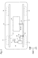
- the vehicle body 12 includes a pair of side members 24 extending in the longitudinal direction of the vehicle 10 with a clearance in the vehicle width direction between them.
- the side member 24 is an extending member extending in the longitudinal direction of the vehicle 10.
- the side member 24 includes a lower part 24A formed opened upward and having two flange portions respectively on either side in its width direction and an upper part 24B to be welded to the two-side flange portions 2402 of the lower part 24A, while the side member has a closed section structure.
- the side member 24 may also have an open section structure, while the invention can be applied to both of the closed and open section structures of the side member 24.
- the bulkhead means a reinforcing part for reinforcing the strength of a closed or open section structure against compression force or tensile force.
- the bulkhead 26 functions as a reinforcing part for reinforcing the strength of the side member 24 against compression force or tensile force applied thereto from a direction perpendicular to the longitudinal direction thereof.
- the bulkheads 26 are formed to extend along the extending direction of the side member 24 and are fixed by welding to the mutually longitudinally spaced multiple portions of the inside surfaces of the lower part 24A.
- the lower part 24A has a bottom wall 2410 and two side walls 2412, 2414 respectively rising from the two sides of the bottom wall 2410 and connectable to two side flanges 2402.
- the bulkheads 26 are welded to the bottom wall 2410 of the side member 24 and to one-side side wall 2414 at the multiple longitudinally-spaced portions of the side member 24.
- reference numerals 2610 and 2612 designate the welded portions respectively.
- the bulkheads 26 function as reinforcing parts for reinforcing the strength of the side member 24 against compression force or tensile force respectively designated by reference signs F1 and F2.
- dash panels 28 for separating the front space Sf of the vehicle body 12 from the vehicle compartment are provided in the near-to-front portions of the paired side members 24and, floor panels 30 are provided backwardly of the rear ends of the dash panels 28.
- the steering system In the front space Sf of the vehicle body 12, there are provided parts constituting the steering system, braking system, power transmission system and air conditioning system of the vehicle 10 including an engine, a traveling motor 2 and an inverter 4.
- the inverter 4 corresponds to a power receiving part for receiving the power of a battery 34.
- the battery 34 is provided below the floor panel 30 between the paired side members 24.
- the battery 34 has a flat rectangular parallelpiped shape and is mounted between the paired side members 24 through a mounting part (not shown).
- the battery 34 has a high-voltage wire 36 extended from one side in the vehicle-width direction and supplies high-voltage dc power through the high-voltage wire 36 to the inverter 4.
- the high-voltage dc power is converted to three-phase ac power by the inverter 4 and is supplied to the traveling motor 2, thereby driving the traveling motor 2.
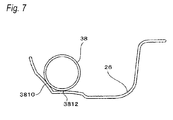
- the high-voltage wire 36 is inserted into a metal pipe (pipe) 38, while the metal pipe 38 with the high-voltage wire 36 inserted therein is wired using the side members 24 and bulkheads 26.
- the side member 24 includes an intermediate part 2410, a front part 2414 and a rear part 2418.
- the intermediate part 2410 is situated below the compartment midway in the longitudinal direction of the vehicle 10.
- the front part 2414 is connected to the front end of the intermediate part 2410 through a bent part 2412 and extends in the longitudinal direction at a higher position than the intermediate part 2410.
- the rear part 2418 is connected to the rear end of the intermediate part 2410 through a bent part 2416 and extends in the longitudinal direction at a higher position than the intermediate part 2410.
- the high-voltage wire 36 is inserted into the metal pipe 38, and the multiple longitudinally-spaced portions of the metal pipe 38 having the high-voltage wire 36 are welded to the bulkheads 26; and, the metal pipe 38 is surrounded by the side members 24 and is disposed with its longitudinal direction extending along the longitudinal direction of the side members 24.
- reference numerals 3810 and 3812 respectively designate welded portions between the metal pipe 38 and bulkheads 26.
- the metal pipe 38 having the high-voltage wire 36 is wired such that it passes through the bent part 2412 of the side member 24 and extends from the rear end of the front part 2414 to the near-to-front portion of the intermediate part 2410.
- the side member 24 has a first insertion opening 40 and a second insertion opening 42 through which the metal pipe 38 having the high-voltage wire 36 can be inserted from outside a space (internal space) surrounded by the side member 24 to inside this space, or, from inside the space to outside the space.
- first and second insertion openings 40 and 42 can advantageously facilitate the wiring of the metal pipe 38 having the high-voltage wire 36 on the side member 24.
- the high-voltage wire 36 together with the side member 24 can be guided from the space surrounded by the side member 24 to outside the space, thereby allowing the protection of the high-voltage wire 36 advantageously.
- the high-voltage wire 36, together with the metal pile 38 can be protruded from the first and second insertion openings 40 and 42 outwardly of the side members 24. Such protrusion of the metal pipe 38 can advantageously protect the high-voltage wire 36 situated outside the side members 24.
- the first insertion opening 40 is formed to penetrate through such portion of the lower member 24A as is opposed to the side portion of the battery 34 from which the high-voltage wire 36 is extended.
- One end 3802 of the metal pipe 38 in the longitudinal direction is protruded laterally of the side member 24 from the first insertion opening 40 and is inserted into the cover of the battery 34, while the end of the high-voltage wire 36 protruded from one end 3802 is electrically connected to the battery 34.
- the second insertion opening 42 is formed to penetrate through such portion of the upper part 24B as is situated near the inverter 4.
- the other end 3804 of the metal pipe 38 in the longitudinal direction is protruded upwardly of the side member 24 from the second insertion opening 42, while the end of the high-voltage wire 36 protruded from the other end 3804 is electrically connected to the inverter 4.
- the second insertion opening 42 is situated more backward than the front end 32A of the strut house 32.
- the strut house 32 is shifted backwardly of the energy absorbing area and, in order to support the suspension device, it is enhanced in rigidity. And, such portion of the vehicle body 12 as is situated behind the strut house 32, in order to protect an occupant in the compartment, is higher in rigidity than the energy absorbing area.
- the second insertion opening 42 situated behind the front end portion 32A of the strut house 32 is protected by the high rigidity portion of the vehicle body 12 hard to crush in collision, thereby allowing the protection of the high-voltage wire 36 in the collision of the vehicle 10 advantageously.
- the second insertion opening 42 is situated before the dash panel 28 of the vehicle 10.
- the portion of the high-voltage wire 36 exposed from the end 3804 of the metal pipe 38 can be shortened, thereby allowing the protection of the high-voltage wire 36 in the collision of the vehicle 10 advantageously.
- the metal pipe 38 having the high-voltage wire 36 intervenes between the battery 34 and inverter 4.
- the multiple portions of at least a part of the metal pipe 38 in the longitudinal direction are welded to the bulkheads 26, while the metal pipe 38 is surrounded by the side members 24 and its longitudinal direction is set along the longitudinal direction of the side members 24.
- the high-voltage wire 36 In wiring the high-voltage wire 36, it may be previously inserted into the metal pipe 38 and the metal pipe 38 having the high-voltage wire 36 may be mounted onto the side members 24 through the bulkheads 26.
- the high-voltage wire 36 may be inserted into the metal pipe 38.
- the metal pipe 38 forms the wiring space for the high-voltage wire 36. Therefore, by a simple operation to insert the high-voltage wire 36 into the metal pipe 38, the high-voltage wire 36 can be wired or replaced, thereby being able to advantageously enhance the efficiency of such wiring or replacing operation.
- the metal pipe 38 has the ends 3802 and 3804 respectively protruding from the first and second insertion openings 40 and 42. This can enhance the efficiency of the wiring or replacing operation of the high-voltage wire 36 more advantageously.
- the longitudinal-direction multiple portions of the metal pipe 38 having the high-voltage wire 36 are welded to the bulkheads 26, whereby the metal pipe 38 is surrounded by the side members 24.
- the high-voltage wire 36 is protected by the metal pipe 38 and also by both the bulkheads 26 and side members 24.
- This embodiment is thus far more advantageous in protecting the high-voltage wire 36 when compared with a case where, as in the prior art, a protection member is attached to the high-voltage wire 36 simply or a high-strength high-voltage wire 36 is used.
- the high-voltage wire 36 is wired using a dead space, that is, the interior of the side member 24. This can reduce the wiring space of the high-voltage wire 36, which provides an advantage in securing the freedom of the layout of the vehicle 10.
- the high-voltage wire 36 is protected by the metal pipe 38 and also by both the bulkheads 26 and side members 24. This can eliminate the use of an expensive high-strength high-voltage wire 36 as the high-voltage wire 36, which provides an advantage in reducing the cost of the high-voltage wire 36.
- the second embodiment is different from the first embodiment in the shape and arrangement of bulkheads but is similar to the first embodiment in remaining structures.
- the same portions and members as in the first embodiment are given the same designations and the description thereof is omitted, while description is given mainly of the different portions.
- Fig. 9 is a perspective view of main portions of a high-voltage wire wiring structure of the second embodiment, wherein, of a side member 24, only a lower part 24A is shown while the illustration of an upper part 24B is omitted.
- Bulkheads 44 are fixed by welding to the multiple longitudinally-spaced portions of the side member 24 and function as parts for reinforcing the side members 24, thereby enhancing the rigidity of the side members 24.
- Each bulkhead 44 is made of a steel-made plate material.
- the bulkhead 44 extends in a direction perpendicular to the extending direction of the side member 24 so as to partition a space between the metal pipe 38 and side member 24.
- the bulkhead 44 constitutes a partition wall to partition the space of the side member 24 surrounding the metal pipe 38.
- each bulkhead 44 has a contour following the section shape of the inner surfaces of the lower and upper parts 24A and 24B, and its outer peripheral edge 4402 is welded to the bottom wall 2410 and side walls 2412 and 2414 of the lower part 24A.
- reference numerals 4410, 4412 and 4414 designate the welded portions respectively.
- the bulkhead 44 with its outer peripheral edge 4402 welded to the inner surfaces of the lower part 24A, functions as a part for reinforcing the strength of the side member 24 against compression force or tensile force shown by designations F1 and F2.
- Each bulkhead 44 has an insertion hole 4404 through which the metal pipe 38 having the high-voltage wire 36 can be inserted.
- the outer peripheral surface of the metal pipe 38 inserted through the insertion holes 4404 and the edges of the insertion holes 4404 are welded together, whereby the multiple portions of the metal pipe 38 are welded to the bulkheads 44.
- the extending member is not limited to the side member 24 but it may also be, for example, a side sill extending in the longitudinal direction of the vehicle 10 and including bulkheads 26 respectively provided in the extending-direction multiple portions thereof, or a cross member extending in the right-and-left direction of the vehicle 10 and including bulkheads 26 respectively provided in the extending-direction multiple portions thereof.
- the extending member is a member to form the skeleton member of the vehicle body 12 such as a side member 24 or cross member
- the high-voltage wire 36 can be more advantageously protected in the collision of the vehicle 10.
- the power receiving part to be connected to the battery 34 through the high-voltage wire need only be capable of receiving the power of the battery 34 and thus it is not limited to the inverter 4.
- the material of the pipe is not limited to the metal but any other material can be used so long as it has a specific strength and can be welded to the bulkhead 26.
- the high-voltage wire since, in vehicle collision, the high-voltage wire is protected by the pipe and also by both the bulkheads and extending members, the high-voltage wire can be protected advantageously.
- the high-voltage wire is wired using a dead space, that is, the interior of the extending member, the wiring space of the high-voltage wire can be reduced and thus the freedom of vehicle layout can be secured advantageously.
- the high-voltage wire can be guided together with the pipe from within a space surrounded by the extending members to outside such space, thereby allowing the protection of the high-voltage wire more advantageously.
- the high-voltage wire can be protected advantageously.
- the distance between the power receiving part and insertion opening can be shortened. This can shorten the portion of the high-voltage wire exposed from the end of the pipe, thereby allowing the protection of the high-voltage wire advantageously.
- the high-voltage wire can be protected advantageously.
Landscapes
- Engineering & Computer Science (AREA)
- Mechanical Engineering (AREA)
- Architecture (AREA)
- Civil Engineering (AREA)
- Structural Engineering (AREA)
- Body Structure For Vehicles (AREA)
- Arrangement Or Mounting Of Propulsion Units For Vehicles (AREA)
- Electric Propulsion And Braking For Vehicles (AREA)
Applications Claiming Priority (2)
| Application Number | Priority Date | Filing Date | Title |
|---|---|---|---|
| JP2013234584 | 2013-11-13 | ||
| JP2014028338A JP6307919B2 (ja) | 2013-11-13 | 2014-02-18 | 車両における高圧電線の配設構造 |
Publications (2)
| Publication Number | Publication Date |
|---|---|
| EP2873566A1 true EP2873566A1 (de) | 2015-05-20 |
| EP2873566B1 EP2873566B1 (de) | 2016-10-26 |
Family
ID=51893908
Family Applications (1)
| Application Number | Title | Priority Date | Filing Date |
|---|---|---|---|
| EP14192946.3A Not-in-force EP2873566B1 (de) | 2013-11-13 | 2014-11-13 | Hochspannungsdraht-Verdrahtungsstruktur in Fahrzeugen |
Country Status (4)
| Country | Link |
|---|---|
| US (1) | US9576701B2 (de) |
| EP (1) | EP2873566B1 (de) |
| JP (1) | JP6307919B2 (de) |
| CN (1) | CN104627096B (de) |
Families Citing this family (11)
| Publication number | Priority date | Publication date | Assignee | Title |
|---|---|---|---|---|
| CN105109426B (zh) * | 2015-09-15 | 2018-03-13 | 北京新能源汽车股份有限公司 | 电动车辆 |
| DE102016117903A1 (de) * | 2016-09-22 | 2018-03-22 | Dr. Ing. H.C. F. Porsche Aktiengesellschaft | Karosserieteilanordnung für ein Kraftfahrzeug und Verfahren zur Herstellung einer derartigen Karosserieteilanordnung |
| JP6642409B2 (ja) * | 2016-12-19 | 2020-02-05 | 住友電装株式会社 | ワイヤハーネスにおける保護部材の保持構造 |
| JP6702203B2 (ja) * | 2017-01-19 | 2020-05-27 | 住友電装株式会社 | 電線保護部材 |
| DE102018213518A1 (de) * | 2018-08-10 | 2020-02-13 | Bayerische Motoren Werke Aktiengesellschaft | Leitungsanordnung, Bauteilanordnung und Arbeitsvorrichtung |
| DE102019109177A1 (de) * | 2019-04-08 | 2020-10-08 | Man Truck & Bus Se | Achslenker für eine Radaufhängung |
| CN111755156B (zh) * | 2020-07-09 | 2021-08-27 | 安徽凌宇电缆科技有限公司 | 一种抗冲击型光伏电缆 |
| NL2026912B1 (en) * | 2020-11-17 | 2022-07-01 | Daf Trucks Nv | Guiding cable with ribbed insulation cover |
| US11848546B2 (en) * | 2021-02-01 | 2023-12-19 | Magna Powertrain Of America, Inc. | High voltage wire protection system for electric vehicles |
| WO2023031950A1 (en) * | 2021-09-06 | 2023-03-09 | Tvs Motor Company Limited | A vehicle |
| DE102023121508A1 (de) | 2023-08-11 | 2025-02-13 | Audi Aktiengesellschaft | Unterbodenverkleidung, Kraftfahrzeug mit einer Unterbodenverkleidung sowie Verfahren zur Herstellung einer Unterbodenverkleidung |
Citations (5)
| Publication number | Priority date | Publication date | Assignee | Title |
|---|---|---|---|---|
| EP0900675A2 (de) * | 1997-09-02 | 1999-03-10 | Daimler-Benz Aktiengesellschaft | Kraftfahrzeugachse |
| JP2008296600A (ja) * | 2007-05-29 | 2008-12-11 | Toyota Auto Body Co Ltd | 自動車のロッカー補強構造 |
| JP2013047029A (ja) | 2011-08-29 | 2013-03-07 | Mitsubishi Motors Corp | 車両における高圧電線の配設構造 |
| WO2013065808A1 (en) * | 2011-10-31 | 2013-05-10 | Yazaki Corporation | Wire harness with protective member |
| WO2013125063A1 (ja) * | 2012-02-23 | 2013-08-29 | 住友電装株式会社 | ワイヤハーネスの配索構造および該配索構造の形成方法 |
Family Cites Families (9)
| Publication number | Priority date | Publication date | Assignee | Title |
|---|---|---|---|---|
| JPS6418784A (en) * | 1987-07-14 | 1989-01-23 | Mazda Motor | Side sill structure of automobile |
| US5668351A (en) * | 1996-02-09 | 1997-09-16 | General Motors Corporation | Conduit housing for vehicle engine compartment having a flexible lip that extends into airflow sealing engagement with the radiation |
| JP4151181B2 (ja) * | 1999-12-10 | 2008-09-17 | 株式会社デンソー | 車両用計器盤内電気配線構造 |
| JP2004224156A (ja) * | 2003-01-22 | 2004-08-12 | Honda Motor Co Ltd | 車両用電力ケーブル保持構造 |
| JP4877400B2 (ja) | 2009-08-05 | 2012-02-15 | 株式会社デンソー | 構築物への配線方法 |
| JP2011097692A (ja) * | 2009-10-28 | 2011-05-12 | Yazaki Corp | ワイヤハーネス |
| JP5434748B2 (ja) | 2009-12-24 | 2014-03-05 | 日立金属株式会社 | 車両用導電路 |
| JP5917806B2 (ja) * | 2011-01-21 | 2016-05-18 | 矢崎総業株式会社 | プロテクタの製造方法及びワイヤハーネスの製造方法 |
| JP5957783B2 (ja) * | 2012-09-03 | 2016-07-27 | 矢崎総業株式会社 | ワイヤハーネス |
-
2014
- 2014-02-18 JP JP2014028338A patent/JP6307919B2/ja not_active Expired - Fee Related
- 2014-11-12 CN CN201410645635.7A patent/CN104627096B/zh not_active Expired - Fee Related
- 2014-11-12 US US14/539,870 patent/US9576701B2/en not_active Expired - Fee Related
- 2014-11-13 EP EP14192946.3A patent/EP2873566B1/de not_active Not-in-force
Patent Citations (5)
| Publication number | Priority date | Publication date | Assignee | Title |
|---|---|---|---|---|
| EP0900675A2 (de) * | 1997-09-02 | 1999-03-10 | Daimler-Benz Aktiengesellschaft | Kraftfahrzeugachse |
| JP2008296600A (ja) * | 2007-05-29 | 2008-12-11 | Toyota Auto Body Co Ltd | 自動車のロッカー補強構造 |
| JP2013047029A (ja) | 2011-08-29 | 2013-03-07 | Mitsubishi Motors Corp | 車両における高圧電線の配設構造 |
| WO2013065808A1 (en) * | 2011-10-31 | 2013-05-10 | Yazaki Corporation | Wire harness with protective member |
| WO2013125063A1 (ja) * | 2012-02-23 | 2013-08-29 | 住友電装株式会社 | ワイヤハーネスの配索構造および該配索構造の形成方法 |
Also Published As
| Publication number | Publication date |
|---|---|
| US9576701B2 (en) | 2017-02-21 |
| EP2873566B1 (de) | 2016-10-26 |
| CN104627096A (zh) | 2015-05-20 |
| US20150129275A1 (en) | 2015-05-14 |
| JP6307919B2 (ja) | 2018-04-11 |
| CN104627096B (zh) | 2017-04-12 |
| JP2015117004A (ja) | 2015-06-25 |
Similar Documents
| Publication | Publication Date | Title |
|---|---|---|
| EP2873566B1 (de) | Hochspannungsdraht-Verdrahtungsstruktur in Fahrzeugen | |
| EP3228527B1 (de) | Mit beweglichem motor ausgestattetes fahrzeug | |
| EP3789273B1 (de) | Fahrzeugfrontstruktur und fahrzeug | |
| JP6396960B2 (ja) | 電池パック | |
| CN108367660B (zh) | 高电压控制设备单元的搭载构造 | |
| US11919382B2 (en) | Electrically driven vehicle | |
| JP5597681B2 (ja) | 車体後部構造 | |
| US8813888B2 (en) | Vehicle body rear structure | |
| US10093249B2 (en) | Electric device mounting structure | |
| JP2017226353A (ja) | 車体の下部構造 | |
| KR102842792B1 (ko) | 하이브리드 차량의 배터리 및 연료탱크 배치구조 | |
| CN113212563B (zh) | 车辆构造 | |
| KR102586934B1 (ko) | 자동차의 전방 차체 구조 | |
| CN114590326A (zh) | 用于电池电动车辆的车身底板 | |
| JP2011020625A (ja) | 電気自動車の搭載構造 | |
| JP2013014276A (ja) | 電気自動車のバッテリ支持構造 | |
| JP6627330B2 (ja) | 車両リアフロア構造 | |
| JP6788438B2 (ja) | 電池パック | |
| JP2014051172A (ja) | 車両の接続部配置構造 | |
| JP2013014275A (ja) | 電気自動車のバッテリ支持構造 | |
| JP2016084023A (ja) | 車両 | |
| JP2016159637A (ja) | ハイブリッド車両 | |
| JP2016181481A (ja) | 車載用バッテリー | |
| JP2013014277A (ja) | 電気自動車の車両用補機支持構造 | |
| JP2010215196A (ja) | 自動車の車体構造 |
Legal Events
| Date | Code | Title | Description |
|---|---|---|---|
| PUAI | Public reference made under article 153(3) epc to a published international application that has entered the european phase |
Free format text: ORIGINAL CODE: 0009012 |
|
| 17P | Request for examination filed |
Effective date: 20141113 |
|
| AK | Designated contracting states |
Kind code of ref document: A1 Designated state(s): AL AT BE BG CH CY CZ DE DK EE ES FI FR GB GR HR HU IE IS IT LI LT LU LV MC MK MT NL NO PL PT RO RS SE SI SK SM TR |
|
| AX | Request for extension of the european patent |
Extension state: BA ME |
|
| 17Q | First examination report despatched |
Effective date: 20151104 |
|
| GRAP | Despatch of communication of intention to grant a patent |
Free format text: ORIGINAL CODE: EPIDOSNIGR1 |
|
| INTG | Intention to grant announced |
Effective date: 20160609 |
|
| GRAS | Grant fee paid |
Free format text: ORIGINAL CODE: EPIDOSNIGR3 |
|
| GRAA | (expected) grant |
Free format text: ORIGINAL CODE: 0009210 |
|
| AK | Designated contracting states |
Kind code of ref document: B1 Designated state(s): AL AT BE BG CH CY CZ DE DK EE ES FI FR GB GR HR HU IE IS IT LI LT LU LV MC MK MT NL NO PL PT RO RS SE SI SK SM TR |
|
| REG | Reference to a national code |
Ref country code: GB Ref legal event code: FG4D |
|
| REG | Reference to a national code |
Ref country code: CH Ref legal event code: EP |
|
| REG | Reference to a national code |
Ref country code: AT Ref legal event code: REF Ref document number: 839763 Country of ref document: AT Kind code of ref document: T Effective date: 20161115 |
|
| REG | Reference to a national code |
Ref country code: IE Ref legal event code: FG4D |
|
| REG | Reference to a national code |
Ref country code: FR Ref legal event code: PLFP Year of fee payment: 3 |
|
| REG | Reference to a national code |
Ref country code: DE Ref legal event code: R096 Ref document number: 602014004464 Country of ref document: DE |
|
| REG | Reference to a national code |
Ref country code: LT Ref legal event code: MG4D |
|
| PG25 | Lapsed in a contracting state [announced via postgrant information from national office to epo] |
Ref country code: BE Free format text: LAPSE BECAUSE OF NON-PAYMENT OF DUE FEES Effective date: 20161130 Ref country code: LV Free format text: LAPSE BECAUSE OF FAILURE TO SUBMIT A TRANSLATION OF THE DESCRIPTION OR TO PAY THE FEE WITHIN THE PRESCRIBED TIME-LIMIT Effective date: 20161026 |
|
| REG | Reference to a national code |
Ref country code: NL Ref legal event code: MP Effective date: 20161026 |
|
| REG | Reference to a national code |
Ref country code: AT Ref legal event code: MK05 Ref document number: 839763 Country of ref document: AT Kind code of ref document: T Effective date: 20161026 |
|
| PG25 | Lapsed in a contracting state [announced via postgrant information from national office to epo] |
Ref country code: LT Free format text: LAPSE BECAUSE OF FAILURE TO SUBMIT A TRANSLATION OF THE DESCRIPTION OR TO PAY THE FEE WITHIN THE PRESCRIBED TIME-LIMIT Effective date: 20161026 Ref country code: SE Free format text: LAPSE BECAUSE OF FAILURE TO SUBMIT A TRANSLATION OF THE DESCRIPTION OR TO PAY THE FEE WITHIN THE PRESCRIBED TIME-LIMIT Effective date: 20161026 Ref country code: NO Free format text: LAPSE BECAUSE OF FAILURE TO SUBMIT A TRANSLATION OF THE DESCRIPTION OR TO PAY THE FEE WITHIN THE PRESCRIBED TIME-LIMIT Effective date: 20170126 Ref country code: GR Free format text: LAPSE BECAUSE OF FAILURE TO SUBMIT A TRANSLATION OF THE DESCRIPTION OR TO PAY THE FEE WITHIN THE PRESCRIBED TIME-LIMIT Effective date: 20170127 |
|
| PG25 | Lapsed in a contracting state [announced via postgrant information from national office to epo] |
Ref country code: NL Free format text: LAPSE BECAUSE OF FAILURE TO SUBMIT A TRANSLATION OF THE DESCRIPTION OR TO PAY THE FEE WITHIN THE PRESCRIBED TIME-LIMIT Effective date: 20161026 Ref country code: PT Free format text: LAPSE BECAUSE OF FAILURE TO SUBMIT A TRANSLATION OF THE DESCRIPTION OR TO PAY THE FEE WITHIN THE PRESCRIBED TIME-LIMIT Effective date: 20170227 Ref country code: PL Free format text: LAPSE BECAUSE OF FAILURE TO SUBMIT A TRANSLATION OF THE DESCRIPTION OR TO PAY THE FEE WITHIN THE PRESCRIBED TIME-LIMIT Effective date: 20161026 Ref country code: FI Free format text: LAPSE BECAUSE OF FAILURE TO SUBMIT A TRANSLATION OF THE DESCRIPTION OR TO PAY THE FEE WITHIN THE PRESCRIBED TIME-LIMIT Effective date: 20161026 Ref country code: RS Free format text: LAPSE BECAUSE OF FAILURE TO SUBMIT A TRANSLATION OF THE DESCRIPTION OR TO PAY THE FEE WITHIN THE PRESCRIBED TIME-LIMIT Effective date: 20161026 Ref country code: HR Free format text: LAPSE BECAUSE OF FAILURE TO SUBMIT A TRANSLATION OF THE DESCRIPTION OR TO PAY THE FEE WITHIN THE PRESCRIBED TIME-LIMIT Effective date: 20161026 Ref country code: IS Free format text: LAPSE BECAUSE OF FAILURE TO SUBMIT A TRANSLATION OF THE DESCRIPTION OR TO PAY THE FEE WITHIN THE PRESCRIBED TIME-LIMIT Effective date: 20170226 Ref country code: BE Free format text: LAPSE BECAUSE OF FAILURE TO SUBMIT A TRANSLATION OF THE DESCRIPTION OR TO PAY THE FEE WITHIN THE PRESCRIBED TIME-LIMIT Effective date: 20161026 Ref country code: AT Free format text: LAPSE BECAUSE OF FAILURE TO SUBMIT A TRANSLATION OF THE DESCRIPTION OR TO PAY THE FEE WITHIN THE PRESCRIBED TIME-LIMIT Effective date: 20161026 Ref country code: ES Free format text: LAPSE BECAUSE OF FAILURE TO SUBMIT A TRANSLATION OF THE DESCRIPTION OR TO PAY THE FEE WITHIN THE PRESCRIBED TIME-LIMIT Effective date: 20161026 |
|
| REG | Reference to a national code |
Ref country code: DE Ref legal event code: R097 Ref document number: 602014004464 Country of ref document: DE |
|
| PG25 | Lapsed in a contracting state [announced via postgrant information from national office to epo] |
Ref country code: DK Free format text: LAPSE BECAUSE OF FAILURE TO SUBMIT A TRANSLATION OF THE DESCRIPTION OR TO PAY THE FEE WITHIN THE PRESCRIBED TIME-LIMIT Effective date: 20161026 Ref country code: SK Free format text: LAPSE BECAUSE OF FAILURE TO SUBMIT A TRANSLATION OF THE DESCRIPTION OR TO PAY THE FEE WITHIN THE PRESCRIBED TIME-LIMIT Effective date: 20161026 Ref country code: EE Free format text: LAPSE BECAUSE OF FAILURE TO SUBMIT A TRANSLATION OF THE DESCRIPTION OR TO PAY THE FEE WITHIN THE PRESCRIBED TIME-LIMIT Effective date: 20161026 Ref country code: MC Free format text: LAPSE BECAUSE OF FAILURE TO SUBMIT A TRANSLATION OF THE DESCRIPTION OR TO PAY THE FEE WITHIN THE PRESCRIBED TIME-LIMIT Effective date: 20161026 Ref country code: CZ Free format text: LAPSE BECAUSE OF FAILURE TO SUBMIT A TRANSLATION OF THE DESCRIPTION OR TO PAY THE FEE WITHIN THE PRESCRIBED TIME-LIMIT Effective date: 20161026 Ref country code: RO Free format text: LAPSE BECAUSE OF FAILURE TO SUBMIT A TRANSLATION OF THE DESCRIPTION OR TO PAY THE FEE WITHIN THE PRESCRIBED TIME-LIMIT Effective date: 20161026 |
|
| REG | Reference to a national code |
Ref country code: IE Ref legal event code: MM4A |
|
| PG25 | Lapsed in a contracting state [announced via postgrant information from national office to epo] |
Ref country code: IT Free format text: LAPSE BECAUSE OF FAILURE TO SUBMIT A TRANSLATION OF THE DESCRIPTION OR TO PAY THE FEE WITHIN THE PRESCRIBED TIME-LIMIT Effective date: 20161026 Ref country code: BG Free format text: LAPSE BECAUSE OF FAILURE TO SUBMIT A TRANSLATION OF THE DESCRIPTION OR TO PAY THE FEE WITHIN THE PRESCRIBED TIME-LIMIT Effective date: 20170126 Ref country code: SM Free format text: LAPSE BECAUSE OF FAILURE TO SUBMIT A TRANSLATION OF THE DESCRIPTION OR TO PAY THE FEE WITHIN THE PRESCRIBED TIME-LIMIT Effective date: 20161026 |
|
| PLBE | No opposition filed within time limit |
Free format text: ORIGINAL CODE: 0009261 |
|
| STAA | Information on the status of an ep patent application or granted ep patent |
Free format text: STATUS: NO OPPOSITION FILED WITHIN TIME LIMIT |
|
| PG25 | Lapsed in a contracting state [announced via postgrant information from national office to epo] |
Ref country code: LU Free format text: LAPSE BECAUSE OF NON-PAYMENT OF DUE FEES Effective date: 20161130 |
|
| 26N | No opposition filed |
Effective date: 20170727 |
|
| REG | Reference to a national code |
Ref country code: FR Ref legal event code: PLFP Year of fee payment: 4 |
|
| PG25 | Lapsed in a contracting state [announced via postgrant information from national office to epo] |
Ref country code: IE Free format text: LAPSE BECAUSE OF NON-PAYMENT OF DUE FEES Effective date: 20161113 Ref country code: SI Free format text: LAPSE BECAUSE OF FAILURE TO SUBMIT A TRANSLATION OF THE DESCRIPTION OR TO PAY THE FEE WITHIN THE PRESCRIBED TIME-LIMIT Effective date: 20161026 |
|
| PG25 | Lapsed in a contracting state [announced via postgrant information from national office to epo] |
Ref country code: HU Free format text: LAPSE BECAUSE OF FAILURE TO SUBMIT A TRANSLATION OF THE DESCRIPTION OR TO PAY THE FEE WITHIN THE PRESCRIBED TIME-LIMIT; INVALID AB INITIO Effective date: 20141113 |
|
| PG25 | Lapsed in a contracting state [announced via postgrant information from national office to epo] |
Ref country code: CY Free format text: LAPSE BECAUSE OF FAILURE TO SUBMIT A TRANSLATION OF THE DESCRIPTION OR TO PAY THE FEE WITHIN THE PRESCRIBED TIME-LIMIT Effective date: 20161026 Ref country code: MK Free format text: LAPSE BECAUSE OF FAILURE TO SUBMIT A TRANSLATION OF THE DESCRIPTION OR TO PAY THE FEE WITHIN THE PRESCRIBED TIME-LIMIT Effective date: 20161026 |
|
| PG25 | Lapsed in a contracting state [announced via postgrant information from national office to epo] |
Ref country code: CH Free format text: LAPSE BECAUSE OF NON-PAYMENT OF DUE FEES Effective date: 20171130 Ref country code: LI Free format text: LAPSE BECAUSE OF NON-PAYMENT OF DUE FEES Effective date: 20171130 |
|
| PG25 | Lapsed in a contracting state [announced via postgrant information from national office to epo] |
Ref country code: MT Free format text: LAPSE BECAUSE OF NON-PAYMENT OF DUE FEES Effective date: 20161113 |
|
| REG | Reference to a national code |
Ref country code: FR Ref legal event code: PLFP Year of fee payment: 5 |
|
| PG25 | Lapsed in a contracting state [announced via postgrant information from national office to epo] |
Ref country code: TR Free format text: LAPSE BECAUSE OF FAILURE TO SUBMIT A TRANSLATION OF THE DESCRIPTION OR TO PAY THE FEE WITHIN THE PRESCRIBED TIME-LIMIT Effective date: 20161026 |
|
| GBPC | Gb: european patent ceased through non-payment of renewal fee |
Effective date: 20181113 |
|
| PG25 | Lapsed in a contracting state [announced via postgrant information from national office to epo] |
Ref country code: GB Free format text: LAPSE BECAUSE OF NON-PAYMENT OF DUE FEES Effective date: 20181113 |
|
| PG25 | Lapsed in a contracting state [announced via postgrant information from national office to epo] |
Ref country code: AL Free format text: LAPSE BECAUSE OF FAILURE TO SUBMIT A TRANSLATION OF THE DESCRIPTION OR TO PAY THE FEE WITHIN THE PRESCRIBED TIME-LIMIT Effective date: 20161026 |
|
| PGFP | Annual fee paid to national office [announced via postgrant information from national office to epo] |
Ref country code: FR Payment date: 20221010 Year of fee payment: 9 |
|
| PGFP | Annual fee paid to national office [announced via postgrant information from national office to epo] |
Ref country code: DE Payment date: 20220621 Year of fee payment: 9 |
|
| REG | Reference to a national code |
Ref country code: DE Ref legal event code: R119 Ref document number: 602014004464 Country of ref document: DE |
|
| PG25 | Lapsed in a contracting state [announced via postgrant information from national office to epo] |
Ref country code: DE Free format text: LAPSE BECAUSE OF NON-PAYMENT OF DUE FEES Effective date: 20240601 |
|
| PG25 | Lapsed in a contracting state [announced via postgrant information from national office to epo] |
Ref country code: FR Free format text: LAPSE BECAUSE OF NON-PAYMENT OF DUE FEES Effective date: 20231130 |
|
| PG25 | Lapsed in a contracting state [announced via postgrant information from national office to epo] |
Ref country code: FR Free format text: LAPSE BECAUSE OF NON-PAYMENT OF DUE FEES Effective date: 20231130 Ref country code: DE Free format text: LAPSE BECAUSE OF NON-PAYMENT OF DUE FEES Effective date: 20240601 |