EP2873855A1 - Procédé et dispositif pour empêcher l'usure excessive dans les engrenages - Google Patents
Procédé et dispositif pour empêcher l'usure excessive dans les engrenages Download PDFInfo
- Publication number
- EP2873855A1 EP2873855A1 EP20130817420 EP13817420A EP2873855A1 EP 2873855 A1 EP2873855 A1 EP 2873855A1 EP 20130817420 EP20130817420 EP 20130817420 EP 13817420 A EP13817420 A EP 13817420A EP 2873855 A1 EP2873855 A1 EP 2873855A1
- Authority
- EP
- European Patent Office
- Prior art keywords
- parts
- gears
- excessive wear
- lubricant
- gear
- Prior art date
- Legal status (The legal status is an assumption and is not a legal conclusion. Google has not performed a legal analysis and makes no representation as to the accuracy of the status listed.)
- Withdrawn
Links
- 238000000034 method Methods 0.000 title claims abstract description 13
- 230000000712 assembly Effects 0.000 title 1
- 238000000429 assembly Methods 0.000 title 1
- 239000002699 waste material Substances 0.000 title 1
- 239000000314 lubricant Substances 0.000 claims abstract description 20
- 230000001050 lubricating effect Effects 0.000 claims abstract description 5
- 238000009826 distribution Methods 0.000 claims description 10
- 238000002347 injection Methods 0.000 claims description 4
- 239000007924 injection Substances 0.000 claims description 4
- 229920000642 polymer Polymers 0.000 claims description 3
- 239000007779 soft material Substances 0.000 claims description 3
- 238000005461 lubrication Methods 0.000 description 14
- 239000004519 grease Substances 0.000 description 7
- 238000013461 design Methods 0.000 description 6
- 238000004519 manufacturing process Methods 0.000 description 4
- 238000005516 engineering process Methods 0.000 description 3
- 208000004188 Tooth Wear Diseases 0.000 description 2
- 230000005611 electricity Effects 0.000 description 2
- 238000010348 incorporation Methods 0.000 description 2
- 238000005096 rolling process Methods 0.000 description 2
- 230000003068 static effect Effects 0.000 description 2
- 230000005540 biological transmission Effects 0.000 description 1
- 230000005465 channeling Effects 0.000 description 1
- 230000000295 complement effect Effects 0.000 description 1
- 230000006835 compression Effects 0.000 description 1
- 238000007906 compression Methods 0.000 description 1
- 238000011161 development Methods 0.000 description 1
- 238000010586 diagram Methods 0.000 description 1
- 238000004870 electrical engineering Methods 0.000 description 1
- 230000010354 integration Effects 0.000 description 1
- 238000005304 joining Methods 0.000 description 1
- 238000003754 machining Methods 0.000 description 1
- 238000012423 maintenance Methods 0.000 description 1
- 239000000463 material Substances 0.000 description 1
- 239000002184 metal Substances 0.000 description 1
- 239000000243 solution Substances 0.000 description 1
- 238000007514 turning Methods 0.000 description 1
Images
Classifications
-
- F—MECHANICAL ENGINEERING; LIGHTING; HEATING; WEAPONS; BLASTING
- F16—ENGINEERING ELEMENTS AND UNITS; GENERAL MEASURES FOR PRODUCING AND MAINTAINING EFFECTIVE FUNCTIONING OF MACHINES OR INSTALLATIONS; THERMAL INSULATION IN GENERAL
- F16H—GEARING
- F16H57/00—General details of gearing
- F16H57/04—Features relating to lubrication or cooling or heating
- F16H57/0456—Lubrication by injection; Injection nozzles or tubes therefor
-
- F—MECHANICAL ENGINEERING; LIGHTING; HEATING; WEAPONS; BLASTING
- F16—ENGINEERING ELEMENTS AND UNITS; GENERAL MEASURES FOR PRODUCING AND MAINTAINING EFFECTIVE FUNCTIONING OF MACHINES OR INSTALLATIONS; THERMAL INSULATION IN GENERAL
- F16H—GEARING
- F16H55/00—Elements with teeth or friction surfaces for conveying motion; Worms, pulleys or sheaves for gearing mechanisms
- F16H55/02—Toothed members; Worms
- F16H55/17—Toothed wheels
-
- F—MECHANICAL ENGINEERING; LIGHTING; HEATING; WEAPONS; BLASTING
- F16—ENGINEERING ELEMENTS AND UNITS; GENERAL MEASURES FOR PRODUCING AND MAINTAINING EFFECTIVE FUNCTIONING OF MACHINES OR INSTALLATIONS; THERMAL INSULATION IN GENERAL
- F16H—GEARING
- F16H57/00—General details of gearing
- F16H57/04—Features relating to lubrication or cooling or heating
- F16H57/042—Guidance of lubricant
- F16H57/043—Guidance of lubricant within rotary parts, e.g. axial channels or radial openings in shafts
- F16H57/0431—Means for guiding lubricant directly onto a tooth surface or to foot areas of a gear, e.g. by holes or grooves in a tooth flank
-
- F—MECHANICAL ENGINEERING; LIGHTING; HEATING; WEAPONS; BLASTING
- F16—ENGINEERING ELEMENTS AND UNITS; GENERAL MEASURES FOR PRODUCING AND MAINTAINING EFFECTIVE FUNCTIONING OF MACHINES OR INSTALLATIONS; THERMAL INSULATION IN GENERAL
- F16H—GEARING
- F16H57/00—General details of gearing
- F16H57/04—Features relating to lubrication or cooling or heating
- F16H57/048—Type of gearings to be lubricated, cooled or heated
- F16H57/0493—Gearings with spur or bevel gears
-
- F—MECHANICAL ENGINEERING; LIGHTING; HEATING; WEAPONS; BLASTING
- F05—INDEXING SCHEMES RELATING TO ENGINES OR PUMPS IN VARIOUS SUBCLASSES OF CLASSES F01-F04
- F05B—INDEXING SCHEME RELATING TO WIND, SPRING, WEIGHT, INERTIA OR LIKE MOTORS, TO MACHINES OR ENGINES FOR LIQUIDS COVERED BY SUBCLASSES F03B, F03D AND F03G
- F05B2260/00—Function
- F05B2260/98—Lubrication
Definitions
- the invention relates to a method and a device to prevent excessive wear in gears.
- the object of the invention is a method and a device for its implementation, which aims to improve gear performance and prevent excessive wear present in machinery gears working under heavy loads, particularly intended to be applied in wind turbines gears, where the method is based on the application of micro-fluidic technology comprising the development of a grease distribution system through parts of soft material (for example polymers) which are arranged in the contact point between the teeth and the notches of the gear.
- soft material for example polymers
- the application field of the present invention falls within the field of industry devoted to the manufacture of wind turbines, focusing on the field of systems intended to improve gears wear.
- the bearings of the variable change of pitch system are subjected to alternating traction and compression stress.
- the yaw system is affected by the same stress cycle, but in this case due to the different wind speed and the small wind direction changes.
- Mashue, A; 2011 [2] proposes a marks system to measure the excessive tooth wear and thus predict the repair before failure occurs.
- a new lubrication system for lubricating the contact point between the two gears that provides the possibility to exactly lubricate the contact area with a control of the amount of grease required, which, moreover, is compatible with both the new wind turbine models and also the currently ongoing wind turbine models in which it allows lubrication of the contact tooth (5) simultaneously with the generation of electricity, thus avoiding generation losses.
- the method proposed by the present invention is based on the application of the micro-fluidic technology and thus the micro manufacturing of a grease distribution system that can be adapted to the dedendum of the gear to be lubricated.
- said part consists of a strip adapted to fit to the gap of the dedendum or tooth root, considering, of course, the incorporation of one of these parts in each of the dedendum determining two ridges or teeth in, at least, those teeth that suffer excessive wear.
- the lubricant distribution strips are preferably made of soft materials (such as polymer) to avoid damage to the gear in case of accidental contact.
- These strips also are provided, each with a plurality of perforations which are lubricant distribution micro-fluidic channels.
- module 12 and 15 pinion teeth similar to those used in Pitch and Yaw gears in wind turbines, we obtain values of width and thickness for the part of 13.4mm and 3mm respectively, values easy to manufacture using micro-technology.
- the lubricant injection through the same will be carried out by integrating them to the own automatic lubrication system usually available in the gears, especially in those of the type to which the invention is primarily intended, that those of wind turbines.
- An example of that integration to said lubrication system consists in connecting the grease pump to a distributor with the corresponding return piping to supply the bearing rolling elements, the toothed crown and to supply the strip for lubrication the wear point.
- a control valve is provided that can be driven mechanically by the engine itself or by the control of the wind turbine when the latter is located in the working position.
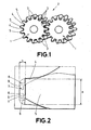
- the method of the invention comprises the lubrication of the contact point between the two wheels (1) of a gear (2) by microfluidics technique, to which end, as seen in Figure 1 , in at least one of said two wheels (1) is provided the incorporation of a microfabrication part (3) housed in each of the notches (4) determining the spaces between the teeth (5) of said wheel (1), where said part (3) is a part having a planar and approximately rectangular configuration and which fits snugly to the dedendum (6) of each of said notches (4).
- each of the parts (3) on the dedendum space (6) of each notch (4) is achieved in each case by dimensioning the part so that the width (a) of the same matches the width of the dedendum (6) in which is housed, and so that the thickness (b) thereof be less or equal than the space between the surface of the crest (7) of the tooth (5) of the engaging wheel and the surface of the dedendum (6) into which the part (3) is housed.
- Each of said parts (3) is also provided with means for channeling lubricant in the area in which they are incorporated, preferably but not limited to, using the own lubrication system of the gear assembly (2).
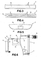
- each of said parts (3) has a plurality of through holes (8) passing through the part from its top surface (3a) to its bottom surface (3b), being, at said bottom surface, connected with longitudinal grooves (9) that in one end of the part (3) converge into a notch (10) open laterally, so that, together, constitute a system of distribution channels for the lubricant, where the latter will be injected into the longitudinal grooves (9) through said lateral opening forming said notch (10).
- the design of the strip is adapted both in dimensions, width (a) and thickness (b), as in the lubricant distribution system.
- FIG. 6 it shows the scheme of operation of the device that, once the parts (3) are assembled, uses for its lubrication the same lubrication system that lubricates the rest of the gear, where the grease pump (11) is shown connected to a distributor (12) with the corresponding return pipe (13), existing a first feed tube (14) supplying grease to the rolling elements of the bearing of the gear (2), a second feed tube (15) grease feeding one of the wheels (1), specifically the toothed crown, and a third feed tube (16) which feeds via the side notches (10) the parts (3) of the device lubricating exactly the wear point. Furthermore, to control the action of the lubrication of said point, in said third feed tube (16) a control valve (17) is arranged which can be mechanically driven by the engine (18) itself or by the control of the wind turbine when located at the working position.
- the device described can be applied to any type of machine, but advantageously, in wind turbines in the change of pitch gear and in the yaw gear.
- the device allows an independent supply of lubricant to each gear of the system, enabling lubricate the tooth (5) in contact while supporting loads.
- the width (a) and thickness (b) of the strips can be adapted to the geometric characteristics of any gear to allow its mounting thereon, and also the geometry and positions of the holes that constitute the lubricant distribution channels system of the strips are also variable.
Landscapes
- Engineering & Computer Science (AREA)
- General Engineering & Computer Science (AREA)
- Mechanical Engineering (AREA)
- General Details Of Gearings (AREA)
Applications Claiming Priority (2)
| Application Number | Priority Date | Filing Date | Title |
|---|---|---|---|
| ES201231081A ES2442451B2 (es) | 2012-07-10 | 2012-07-10 | Procedimiento y dispositivo para prevenir el desgaste excesivo en engranajes |
| PCT/ES2013/070494 WO2014009588A1 (fr) | 2012-07-10 | 2013-07-09 | Procédé et dispositif pour empêcher l'usure excessive dans les engrenages |
Publications (2)
| Publication Number | Publication Date |
|---|---|
| EP2873855A1 true EP2873855A1 (fr) | 2015-05-20 |
| EP2873855A4 EP2873855A4 (fr) | 2016-04-13 |
Family
ID=49915452
Family Applications (1)
| Application Number | Title | Priority Date | Filing Date |
|---|---|---|---|
| EP13817420.6A Withdrawn EP2873855A4 (fr) | 2012-07-10 | 2013-07-09 | Procédé et dispositif pour empêcher l'usure excessive dans les engrenages |
Country Status (4)
| Country | Link |
|---|---|
| US (1) | US20150114758A1 (fr) |
| EP (1) | EP2873855A4 (fr) |
| ES (1) | ES2442451B2 (fr) |
| WO (1) | WO2014009588A1 (fr) |
Families Citing this family (6)
| Publication number | Priority date | Publication date | Assignee | Title |
|---|---|---|---|---|
| EP2784308B1 (fr) * | 2013-03-25 | 2016-10-05 | Alstom Renovables España, S.L. | Une commande de pale avec un disque latéral à lubrifier |
| CN203809218U (zh) * | 2013-10-30 | 2014-09-03 | 通用电气公司 | 用于对齿轮进行润滑的系统 |
| ES2479365B1 (es) * | 2014-03-14 | 2015-04-30 | Laulagun Bearings, S.A. | Sistema de lubricación de engranajes |
| EP3604803B1 (fr) * | 2018-08-03 | 2023-07-12 | Universität Stuttgart | Procédé de fonctionnement d'une chaîne cinématique et produit de programme |
| US10640299B1 (en) | 2019-04-17 | 2020-05-05 | Flexicon Corporation | Wear indicator for sprocket tip |
| CN113090737B (zh) * | 2021-04-30 | 2022-02-11 | 郑州轻工业大学 | 一种带有齿轮磨损程度检测组件的齿轮箱及其工作方法 |
Family Cites Families (27)
| Publication number | Priority date | Publication date | Assignee | Title |
|---|---|---|---|---|
| US3424022A (en) * | 1967-01-23 | 1969-01-28 | Babcock & Wilcox Co | Hydrostatic gearing |
| NO129163B (fr) * | 1971-07-15 | 1974-03-04 | N Tharaldsen | |
| JPS5614657A (en) * | 1979-07-11 | 1981-02-12 | Japanese National Railways<Jnr> | Lubricant liquid feed system for reduction gear for railway train |
| FR2550599B1 (fr) * | 1983-08-11 | 1986-11-14 | Foueillassar Jean Marie | Dispositif pour ameliorer la lubrification des engrenages |
| US5242033A (en) * | 1991-09-13 | 1993-09-07 | General Electric Company | High power gear cooling system |
| US5622239A (en) * | 1995-07-14 | 1997-04-22 | A.T.S. Electro-Lube Holdings Ltd. | Gear wheel lubricator |
| FR2799254B1 (fr) * | 1999-09-30 | 2003-05-30 | Defontaine | Systeme de liaison d'une couronne dentee de demarreur sur un support lie a l'arbre de sortie d'un moteur thermique |
| JP4182408B2 (ja) * | 2003-01-21 | 2008-11-19 | 株式会社ジェイテクト | 減速機およびこれを備える電動式動力舵取装置 |
| DE10321535B3 (de) * | 2003-05-14 | 2004-10-28 | Repower Systems Ag | Vorrichtung zur Verstellung des Anstellwinkels eines Rotorblatts einer Windkraftanlage |
| DE202005014699U1 (de) | 2005-09-16 | 2005-12-08 | Baier & Köppel GmbH & Co | Pitcheinstellvorrichtung für eine Windkraftanlage |
| DE202005015774U1 (de) | 2005-10-07 | 2007-02-15 | Liebherr-Werk Biberach Gmbh | Stellantrieb zur Einstellung des Anstellwinkels eines Rotorblatts |
| US20070175706A1 (en) * | 2006-01-30 | 2007-08-02 | Honeywell International, Inc. | Positive lubrication of a meshing gear |
| DE202006011330U1 (de) * | 2006-05-16 | 2006-09-28 | Lincoln Gmbh & Co. Kg | Schmiereinrichtung mit Schmierritzel |
| WO2008074320A1 (fr) | 2006-12-18 | 2008-06-26 | Vestas Wind Systems A/S | Système d'engrenage pour une commande de lacet ou une commande de pas pour une éolienne |
| DE202007004103U1 (de) * | 2007-03-16 | 2007-06-06 | Lincoln Gmbh | Schmierritzel und Schmiereinrichtung |
| US8047332B2 (en) * | 2007-05-08 | 2011-11-01 | Raytheon Company | Direct grease injection for large open gearing |
| US8287238B2 (en) | 2008-02-29 | 2012-10-16 | General Electric Company | Hub pitch gear repair method |
| ES2442176T3 (es) * | 2009-10-23 | 2014-02-10 | Vestas Wind Systems A/S | Sistema de lubricación para un sistema de engranaje de una turbina eólica que proporciona lubricación de emergencia |
| US9086055B2 (en) * | 2010-01-11 | 2015-07-21 | General Electric Company | Lubrication of fluid turbine gearbox during idling or loss of electric grid |
| US8696314B2 (en) | 2010-06-15 | 2014-04-15 | General Electric Company | Gear set, wind turbine incorporating such a gear set and method of servicing a wind turbine |
| US20110138951A1 (en) | 2010-09-28 | 2011-06-16 | General Electric Company | Wind turbine with gear indicating wear |
| WO2012048711A1 (fr) * | 2010-10-14 | 2012-04-19 | Vestas Wind Systems A/S | Pignon de lubrification |
| JP5422547B2 (ja) * | 2010-12-20 | 2014-02-19 | 三菱重工業株式会社 | 風力発電装置の軸受部給油構造 |
| EP2751467A4 (fr) * | 2011-08-30 | 2015-05-13 | Stephania Holdings Inc | Procédés de commande d'un dispositif de lubrification, procédés de communication et dispositifs et systèmes |
| US9033109B2 (en) * | 2012-01-31 | 2015-05-19 | General Electric Company | System and method for lubricating gears in a wind turbine |
| EP2784308B1 (fr) * | 2013-03-25 | 2016-10-05 | Alstom Renovables España, S.L. | Une commande de pale avec un disque latéral à lubrifier |
| CN203809218U (zh) * | 2013-10-30 | 2014-09-03 | 通用电气公司 | 用于对齿轮进行润滑的系统 |
-
2012
- 2012-07-10 ES ES201231081A patent/ES2442451B2/es active Active
-
2013
- 2013-07-09 US US14/406,846 patent/US20150114758A1/en not_active Abandoned
- 2013-07-09 WO PCT/ES2013/070494 patent/WO2014009588A1/fr not_active Ceased
- 2013-07-09 EP EP13817420.6A patent/EP2873855A4/fr not_active Withdrawn
Also Published As
| Publication number | Publication date |
|---|---|
| ES2442451B2 (es) | 2014-05-23 |
| EP2873855A4 (fr) | 2016-04-13 |
| WO2014009588A1 (fr) | 2014-01-16 |
| US20150114758A1 (en) | 2015-04-30 |
| ES2442451A1 (es) | 2014-02-11 |
Similar Documents
| Publication | Publication Date | Title |
|---|---|---|
| EP2873855A1 (fr) | Procédé et dispositif pour empêcher l'usure excessive dans les engrenages | |
| Smolders et al. | Reliability analysis and prediction of wind turbine gearboxes | |
| CN101878382A (zh) | 用于齿轮的纹理表面 | |
| EP3589839B1 (fr) | Unité de réglage pour régler l'azimut et/ou le pas d'une éolienne et procédé | |
| EP2486276B1 (fr) | Chaîne cinématique et éolienne | |
| CN102979857A (zh) | 轴承脂润滑风电双摆线变桨减速器 | |
| WO2012004067A1 (fr) | Transmission | |
| CN201326521Y (zh) | 风力发电机组滑动式偏航轴承装置 | |
| CN103423087B (zh) | 一种兆瓦级风电机组变桨自动润滑系统的控制方法 | |
| CN103791034A (zh) | 轴承用脂润滑两级行星风电增速箱 | |
| Terrell et al. | Wind turbine tribology | |
| CN103791033A (zh) | 轴承用脂润滑双联双臂式风电增速箱 | |
| Nam et al. | Dynamic life prediction of pitch and yaw bearings for wind turbine | |
| Arafa et al. | Manufacturability and viability of different c-gear types: a comparative study | |
| WO2020239280A1 (fr) | Transmission présentant une régulation améliorée de lubrifiant | |
| Wasilczuk et al. | Analysis of failures of high speed shaft bearing system in a wind turbine | |
| CN203892471U (zh) | 运行平稳的高载荷齿轮装置 | |
| WO2011042084A2 (fr) | Chaîne cinématique et éolienne | |
| Park et al. | Optimal design of wind turbine gearbox using helix modification | |
| ES2442390A1 (es) | Sistema y procedimiento sustentador, propulsor y estabilizador para aeronaves de despegue y aterrizaje vertical, mejorado | |
| Farré-Lladós et al. | New lubrication device to minimize wear at the pitch gear | |
| CN103089929A (zh) | 轴承用脂润滑兆瓦级准行星半直驱风电增速箱 | |
| CN102979887A (zh) | 轴承脂润滑风电摆线变桨减速器 | |
| CN119384570A (zh) | 行星齿轮箱和风电设备 | |
| EP4571147A1 (fr) | Système d'huile lubrifiante pour la lubrification d'un couplage d'une transmission |
Legal Events
| Date | Code | Title | Description |
|---|---|---|---|
| PUAI | Public reference made under article 153(3) epc to a published international application that has entered the european phase |
Free format text: ORIGINAL CODE: 0009012 |
|
| 17P | Request for examination filed |
Effective date: 20150114 |
|
| AK | Designated contracting states |
Kind code of ref document: A1 Designated state(s): AL AT BE BG CH CY CZ DE DK EE ES FI FR GB GR HR HU IE IS IT LI LT LU LV MC MK MT NL NO PL PT RO RS SE SI SK SM TR |
|
| AX | Request for extension of the european patent |
Extension state: BA ME |
|
| DAX | Request for extension of the european patent (deleted) | ||
| RA4 | Supplementary search report drawn up and despatched (corrected) |
Effective date: 20160316 |
|
| RIC1 | Information provided on ipc code assigned before grant |
Ipc: F16H 57/04 20060101AFI20160316BHEP |
|
| GRAP | Despatch of communication of intention to grant a patent |
Free format text: ORIGINAL CODE: EPIDOSNIGR1 |
|
| STAA | Information on the status of an ep patent application or granted ep patent |
Free format text: STATUS: GRANT OF PATENT IS INTENDED |
|
| INTG | Intention to grant announced |
Effective date: 20200107 |
|
| GRAJ | Information related to disapproval of communication of intention to grant by the applicant or resumption of examination proceedings by the epo deleted |
Free format text: ORIGINAL CODE: EPIDOSDIGR1 |
|
| STAA | Information on the status of an ep patent application or granted ep patent |
Free format text: STATUS: REQUEST FOR EXAMINATION WAS MADE |
|
| INTC | Intention to grant announced (deleted) | ||
| GRAP | Despatch of communication of intention to grant a patent |
Free format text: ORIGINAL CODE: EPIDOSNIGR1 |
|
| STAA | Information on the status of an ep patent application or granted ep patent |
Free format text: STATUS: GRANT OF PATENT IS INTENDED |
|
| INTG | Intention to grant announced |
Effective date: 20201217 |
|
| STAA | Information on the status of an ep patent application or granted ep patent |
Free format text: STATUS: THE APPLICATION IS DEEMED TO BE WITHDRAWN |
|
| 18D | Application deemed to be withdrawn |
Effective date: 20210202 |