EP2873877A1 - Fixation de dilatation autotaraudeuse et son procédé de fabrication - Google Patents
Fixation de dilatation autotaraudeuse et son procédé de fabrication Download PDFInfo
- Publication number
- EP2873877A1 EP2873877A1 EP20130193389 EP13193389A EP2873877A1 EP 2873877 A1 EP2873877 A1 EP 2873877A1 EP 20130193389 EP20130193389 EP 20130193389 EP 13193389 A EP13193389 A EP 13193389A EP 2873877 A1 EP2873877 A1 EP 2873877A1
- Authority
- EP
- European Patent Office
- Prior art keywords
- self
- expansion
- drilling
- zone
- drill
- Prior art date
- Legal status (The legal status is an assumption and is not a legal conclusion. Google has not performed a legal analysis and makes no representation as to the accuracy of the status listed.)
- Granted
Links
Images


Classifications
-
- F—MECHANICAL ENGINEERING; LIGHTING; HEATING; WEAPONS; BLASTING
- F16—ENGINEERING ELEMENTS AND UNITS; GENERAL MEASURES FOR PRODUCING AND MAINTAINING EFFECTIVE FUNCTIONING OF MACHINES OR INSTALLATIONS; THERMAL INSULATION IN GENERAL
- F16B—DEVICES FOR FASTENING OR SECURING CONSTRUCTIONAL ELEMENTS OR MACHINE PARTS TOGETHER, e.g. NAILS, BOLTS, CIRCLIPS, CLAMPS, CLIPS OR WEDGES; JOINTS OR JOINTING
- F16B13/00—Dowels or other devices fastened in walls or the like by inserting them in holes made therein for that purpose
- F16B13/04—Dowels or other devices fastened in walls or the like by inserting them in holes made therein for that purpose with parts gripping in the hole or behind the reverse side of the wall after inserting from the front
- F16B13/06—Dowels or other devices fastened in walls or the like by inserting them in holes made therein for that purpose with parts gripping in the hole or behind the reverse side of the wall after inserting from the front combined with expanding sleeve
- F16B13/061—Dowels or other devices fastened in walls or the like by inserting them in holes made therein for that purpose with parts gripping in the hole or behind the reverse side of the wall after inserting from the front combined with expanding sleeve of the buckling type
-
- F—MECHANICAL ENGINEERING; LIGHTING; HEATING; WEAPONS; BLASTING
- F16—ENGINEERING ELEMENTS AND UNITS; GENERAL MEASURES FOR PRODUCING AND MAINTAINING EFFECTIVE FUNCTIONING OF MACHINES OR INSTALLATIONS; THERMAL INSULATION IN GENERAL
- F16B—DEVICES FOR FASTENING OR SECURING CONSTRUCTIONAL ELEMENTS OR MACHINE PARTS TOGETHER, e.g. NAILS, BOLTS, CIRCLIPS, CLAMPS, CLIPS OR WEDGES; JOINTS OR JOINTING
- F16B13/00—Dowels or other devices fastened in walls or the like by inserting them in holes made therein for that purpose
- F16B13/002—Dowels or other devices fastened in walls or the like by inserting them in holes made therein for that purpose self-cutting
Definitions
- the present invention relates to an expansion fastener integrally formed of a sheet metal material, and more particularly to an expansion fastener capable of self-drilling a hole.
- An expansion fastening device is usually used to fixedly connect multiple sheet workpieces, such as building panels, to one another, and includes a bolt and an expansion fastener.
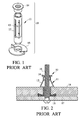
- Fig. 1 shows a typical conventional expansion fastener 10, which includes a barrel body 11 having a plurality of longitudinally extended elongated slots 12 formed thereon to define a plurality of laterally spaced middle bars 13; a nut 14 connected to a head of the barrel body 11; and a bottom cover 15 connected to a bottom of the barrel body 11.
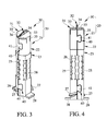
- a bolt 16 can be extended through the bottom cover 15 and the barrel body 11 of the expansion fastener 10 to mesh with the nut 14.
- the middle bars 13 are brought to expand outward and become deformed.
- the deformed middle bars 13 and the bolt 16 together lock an attached object 17 to a supporting object 18.
- the conventional expansion fastener 10 is disadvantageous in terms of assembling and installation thereof.
- First, the nut 14 and the bottom cover 15 are connected to the barrel body 11 by welding, which is time and labor consuming to result in high manufacturing cost of the expansion fastener 10.
- the above installation is apparently troublesome and consumes a lot of time and labor. It is therefore desirable to overcome these disadvantages.
- a primary object of the present invention is to provide a self-drilling expansion fastener, with which a user can lock two or more sheet workpieces together with only one installation step to largely simplify the working procedure and upgrade the working efficiency.
- Another object of the present invention is to provide a method of integrally forming a self-drilling expansion fastener from a sheet metal material through a series of punching and stamping procedures, so that the self-drilling expansion fastener can be easily manufactured with upgraded production efficiency.
- the self-drilling expansion fastener is integrally formed of a sheet metal material for locking two or more sheet workpieces together, and includes an expansion structure and a drill structure located at a head of the expansion structure.
- the expansion structure has a plurality of internal threads and a plurality of force-distributing bars.
- the drill structure has a chip guard for covering the head of the expansion structure, and a drill forward projected from the chip guard for self-drilling a hole on the sheet workpieces, so that the expansion structure can be extended through the sheet workpieces and tightly received in the drilled hole with the force-distributing bars fully located behind the sheet workpieces.
- the method according to the present invention for integrally forming a self-drilling expansion fastener includes the following steps:
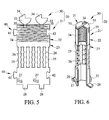
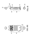
- a self-drilling expansion fastener 20 is integrally formed of a sheet metal material, and includes an expansion structure 21 and a drill structure 30 located at a head of the expansion structure 21.
- the expansion structure 21 has a front portion formed into an internally threaded body portion 22 and a rear portion formed into a barrel body portion 23.
- the internally threaded body portion 22 is a cylindrical hollow body and defines a plurality of internal threads 24.
- the barrel body portion 23 is a hexagonal hollow body and internally defines a hex bore.
- the barrel body portion 23 includes a plurality of laterally spaced force-distributing bars 25. Once the barrel body portion 23 is subjected to an axial pull, stress occurs at the force-distributing bars 25. In other words, the force-distributing bars 25 together form a weakening zone.
- there are six axially extended force-distributing bars 25 being laterally equally spaced on the barrel body portion 23, such that a spacing slot 26 is formed between any two adjacent force-distributing bars 25.
- the barrel body portion 23 includes at least one retaining wing 27. In the illustrated preferred embodiment, as shown in Fig.
- the barrel body portion 23 there are two retaining wings 27 formed on the barrel body portion 23 by stamping, so that these retaining wings 27 are outward protruded from a wall surface of the barrel body portion 23 and are slant at a fixed angle relative to a horizontal rear end of the barrel body portion 23.
- the barrel body portion 23 includes at least one stopper 28 formed on the rear end thereof.
- the illustrated preferred embodiment of the present invention has two diametrically opposite stoppers 28, which are respectively upward bent from the rear end of the barrel body portion 23 to a sidewardly projected position.
- the drill structure 30 includes a chip guard 31 and a drill 32.
- the chip guard 31 includes two side covers 33, which are extended from the internally threaded body portion 22 and bent toward each other to together cover a front end of the internally threaded body portion 22. It is noted two slits 35 are formed at two lateral sides of the joint of each side cover 33 and the internally threaded body portion 22.
- the drill 32 consists of two drill bits 34, which are forward projected from top surfaces of the two side covers 33.
- the expansion structure 21 further includes at least one coupling device 40, which consists of a lug portion 41 and a notch portion 42 correspondingly located opposite to the lug portion 41, such that the lug portion 41 and the notch portion 42 can be engaged with and locked to each other.
- at least one coupling device 40 which consists of a lug portion 41 and a notch portion 42 correspondingly located opposite to the lug portion 41, such that the lug portion 41 and the notch portion 42 can be engaged with and locked to each other.
- Figs. 7A to 7C illustrate the steps of installing the self-drilling expansion fastener 20 on sheet workpieces.
- more than two layers may be fastened by the fastener of the invention. At this point, as shown in Fig.
- the force-distributing bars 25 are located behind the supporting object 51 and the retaining wings 27 are embedded in a peripheral wall of the drilled hole on the attached object 50, bringing the self-drilling expansion fastener 20 to firmly associate with the attached object 50 and the supporting object 51.
- a matching hexagonal tool 54 can be inserted into the barrel body portion 23 to facilitate the rotation of the self-drilling expansion fastener 20, allowing the drill 32 to drill a hole on the attached object 50 and the supporting object 51.
- the chip guard 31 functions to prevent any chips of the workpieces 50, 51 from getting into the expansion structure 21. Thereafter, as shown in Fig.
- the self-drilling expansion fastener 20 is integrally formed and has the ability of self-drilling a hole, and can therefore be manufactured with fewer components to reduce the production and installation costs thereof.
- the self-drilling expansion fastener 20 is formed of a sheet metal material through a series of punching and stamping procedures.
- Figs. 8A to 8I sequentially illustrate the steps included in a method of the present invention for forming the self-drilling expansion fastener 20.
- unnecessary portions are removed from a sheet metal raw material to obtain the sheet metal material having dimensions for forming the self-drilling expansion fastener 20;
- a reference line "a" is defined to determine an expansion structure zone 60 and a drill structure zone 70 on the obtained sheet metal material; and the expansion structure zone 60 is punched at a specified location to obtain at least one coupling device 61 and at a rear portion to obtain required stoppers 62.
- the expansion structure zone 60 is stamped at a specified location, which is defined as a thread forming zone 64, to obtain required threads 63.
- the expansion structure zone 60 is punched at a predetermined location, which is defined as a barrel body forming zone 66, to obtain a plurality of required force-distributing bars 65; and the drill structure zone 70 is punched at predetermined locations to obtain required side covers 71 and drill bits 72. Thereafter, as can be seen in Fig.
- the barrel body forming zone 66 is stamped at predetermined locations to obtain required retaining wings 67, and the thread forming zone 64 is punched at predetermined locations to obtain slits 73 at joints of the side covers 71 and the thread forming zone 64.
- the stoppers 62, the side covers 71 and drill bits 72 are bent, so that the side covers 71 together form a required chip guard 74 and the drill bits 72 together form a required drill 75.
- the thread forming zone 64 and the barrel body forming zone 66 are subjected to a series of stamping to respectively obtain a required configuration.
- the thread forming zone 64 is formed into a near-cylindrical hollow body and the barrel body forming zone 66 is formed into a hexagonal hollow body internally defining a hexagonal bore.
- the coupling devices 61 are closed to complete the self-drilling expansion fastener 20 of the present invention.
- the self-drilling expansion fastener 20 can be easily and quickly completed with largely simplified procedures, shortened working time and lowered manufacturing cost.
Landscapes
- Engineering & Computer Science (AREA)
- General Engineering & Computer Science (AREA)
- Mechanical Engineering (AREA)
- Dowels (AREA)
Priority Applications (4)
| Application Number | Priority Date | Filing Date | Title |
|---|---|---|---|
| PL13193389T PL2873877T3 (pl) | 2013-11-18 | 2013-11-18 | Samonawiercająca kotwa rozporowa oraz metoda jej formowania |
| EP13193389.7A EP2873877B1 (fr) | 2013-11-18 | 2013-11-18 | Fixation de dilatation autotaraudeuse et son procédé de fabrication |
| PT131933897T PT2873877T (pt) | 2013-11-18 | 2013-11-18 | Fixador de expansão auto-perfurante e método para formar o mesmo |
| ES13193389.7T ES2620003T3 (es) | 2013-11-18 | 2013-11-18 | Cierre de expansión autoperforante y método de formación del mismo |
Applications Claiming Priority (1)
| Application Number | Priority Date | Filing Date | Title |
|---|---|---|---|
| EP13193389.7A EP2873877B1 (fr) | 2013-11-18 | 2013-11-18 | Fixation de dilatation autotaraudeuse et son procédé de fabrication |
Publications (2)
| Publication Number | Publication Date |
|---|---|
| EP2873877A1 true EP2873877A1 (fr) | 2015-05-20 |
| EP2873877B1 EP2873877B1 (fr) | 2017-01-04 |
Family
ID=49596142
Family Applications (1)
| Application Number | Title | Priority Date | Filing Date |
|---|---|---|---|
| EP13193389.7A Active EP2873877B1 (fr) | 2013-11-18 | 2013-11-18 | Fixation de dilatation autotaraudeuse et son procédé de fabrication |
Country Status (4)
| Country | Link |
|---|---|
| EP (1) | EP2873877B1 (fr) |
| ES (1) | ES2620003T3 (fr) |
| PL (1) | PL2873877T3 (fr) |
| PT (1) | PT2873877T (fr) |
Cited By (1)
| Publication number | Priority date | Publication date | Assignee | Title |
|---|---|---|---|---|
| CN115451002A (zh) * | 2021-06-09 | 2022-12-09 | 广东东箭汽车科技股份有限公司 | 一种膨胀安装结构及其使用方法 |
Citations (5)
| Publication number | Priority date | Publication date | Assignee | Title |
|---|---|---|---|---|
| FR2546989A1 (fr) * | 1983-06-03 | 1984-12-07 | Manuf Fse Oeillets Metalli | Cheville d'ancrage de vis pour pose en aveugle |
| EP0378907A1 (fr) * | 1988-12-21 | 1990-07-25 | Emhart Inc. | Chevilles d'ancrage aveugles pour des vis à fixation |
| EP1471265A2 (fr) * | 2003-04-24 | 2004-10-27 | BLACK & DECKER INC. | Ancre de mur pour une vis, et assemblage constituée par une telle ancre de mur et une vis |
| WO2009107018A2 (fr) * | 2008-02-13 | 2009-09-03 | Société De Prospection Et D'inventions Techniques - Spit | Goujon auto-perçeur |
| JP2010164180A (ja) * | 2009-01-19 | 2010-07-29 | Wakai & Co Ltd | 拡開アンカー |
-
2013
- 2013-11-18 PL PL13193389T patent/PL2873877T3/pl unknown
- 2013-11-18 PT PT131933897T patent/PT2873877T/pt unknown
- 2013-11-18 ES ES13193389.7T patent/ES2620003T3/es active Active
- 2013-11-18 EP EP13193389.7A patent/EP2873877B1/fr active Active
Patent Citations (5)
| Publication number | Priority date | Publication date | Assignee | Title |
|---|---|---|---|---|
| FR2546989A1 (fr) * | 1983-06-03 | 1984-12-07 | Manuf Fse Oeillets Metalli | Cheville d'ancrage de vis pour pose en aveugle |
| EP0378907A1 (fr) * | 1988-12-21 | 1990-07-25 | Emhart Inc. | Chevilles d'ancrage aveugles pour des vis à fixation |
| EP1471265A2 (fr) * | 2003-04-24 | 2004-10-27 | BLACK & DECKER INC. | Ancre de mur pour une vis, et assemblage constituée par une telle ancre de mur et une vis |
| WO2009107018A2 (fr) * | 2008-02-13 | 2009-09-03 | Société De Prospection Et D'inventions Techniques - Spit | Goujon auto-perçeur |
| JP2010164180A (ja) * | 2009-01-19 | 2010-07-29 | Wakai & Co Ltd | 拡開アンカー |
Cited By (1)
| Publication number | Priority date | Publication date | Assignee | Title |
|---|---|---|---|---|
| CN115451002A (zh) * | 2021-06-09 | 2022-12-09 | 广东东箭汽车科技股份有限公司 | 一种膨胀安装结构及其使用方法 |
Also Published As
| Publication number | Publication date |
|---|---|
| EP2873877B1 (fr) | 2017-01-04 |
| ES2620003T3 (es) | 2017-06-27 |
| PL2873877T3 (pl) | 2017-09-29 |
| PT2873877T (pt) | 2017-02-22 |
Similar Documents
| Publication | Publication Date | Title |
|---|---|---|
| US9309906B2 (en) | Self-drilling expansion fastener and method of forming same | |
| US9714731B2 (en) | Threaded connector locking device | |
| EP1472465B1 (fr) | Element de fixation cisaillable | |
| US20150219136A1 (en) | Push Fastener | |
| US20100129174A1 (en) | Piercing standoff | |
| WO2014014699A1 (fr) | Punaise | |
| TWI742301B (zh) | 具有壓縮套之插入式緊固件、包含此緊固件的組合件以及將插件安裝至板中之方法 | |
| WO2009107018A2 (fr) | Goujon auto-perçeur | |
| EP2873877B1 (fr) | Fixation de dilatation autotaraudeuse et son procédé de fabrication | |
| KR101404938B1 (ko) | 펀칭작업이 필요없는 개선된 세트 앵커볼트 | |
| AU2013267040B2 (en) | Self-drilling expansion fastener and method of forming same | |
| CA2833811C (fr) | Attache a expansion a forage autonome et procede de formation de celle-ci | |
| TWI553235B (zh) | Self - drilling and Pulling Fastener and Its Forming Method | |
| JP2020020372A (ja) | ブラインドボルト | |
| JP6709049B2 (ja) | 締結具及び締結構造 | |
| RU2563412C2 (ru) | Самосверлящее расширительное крепежное средство и способ его изготовления | |
| EP4352334B1 (fr) | Connexion de tubulaires dans un puits de forage | |
| WO2016089299A1 (fr) | Rivet | |
| US20180156259A1 (en) | Micro-Standoff for Blind Holes | |
| KR101404949B1 (ko) | 더블 캡 앵커볼트 | |
| EP4491889B1 (fr) | Dispositif de fixation aveugle pour fixer une pièce à une pièce de base | |
| US11739780B2 (en) | Functional element | |
| CN104564962B (zh) | 自钻式拉爆扣件及其成型方法 | |
| KR20150057571A (ko) | 자체 천공형 앵커 클램프 및 그 성형 방법 | |
| EP3622185B1 (fr) | Dispositif de fixation |
Legal Events
| Date | Code | Title | Description |
|---|---|---|---|
| PUAI | Public reference made under article 153(3) epc to a published international application that has entered the european phase |
Free format text: ORIGINAL CODE: 0009012 |
|
| 17P | Request for examination filed |
Effective date: 20131118 |
|
| AK | Designated contracting states |
Kind code of ref document: A1 Designated state(s): AL AT BE BG CH CY CZ DE DK EE ES FI FR GB GR HR HU IE IS IT LI LT LU LV MC MK MT NL NO PL PT RO RS SE SI SK SM TR |
|
| AX | Request for extension of the european patent |
Extension state: BA ME |
|
| R17P | Request for examination filed (corrected) |
Effective date: 20151120 |
|
| RBV | Designated contracting states (corrected) |
Designated state(s): AL AT BE BG CH CY CZ DE DK EE ES FI FR GB GR HR HU IE IS IT LI LT LU LV MC MK MT NL NO PL PT RO RS SE SI SK SM TR |
|
| GRAP | Despatch of communication of intention to grant a patent |
Free format text: ORIGINAL CODE: EPIDOSNIGR1 |
|
| RIC1 | Information provided on ipc code assigned before grant |
Ipc: F16B 13/06 20060101AFI20160222BHEP |
|
| INTG | Intention to grant announced |
Effective date: 20160316 |
|
| GRAS | Grant fee paid |
Free format text: ORIGINAL CODE: EPIDOSNIGR3 |
|
| GRAA | (expected) grant |
Free format text: ORIGINAL CODE: 0009210 |
|
| AK | Designated contracting states |
Kind code of ref document: B1 Designated state(s): AL AT BE BG CH CY CZ DE DK EE ES FI FR GB GR HR HU IE IS IT LI LT LU LV MC MK MT NL NO PL PT RO RS SE SI SK SM TR |
|
| REG | Reference to a national code |
Ref country code: GB Ref legal event code: FG4D |
|
| REG | Reference to a national code |
Ref country code: CH Ref legal event code: EP |
|
| REG | Reference to a national code |
Ref country code: AT Ref legal event code: REF Ref document number: 859534 Country of ref document: AT Kind code of ref document: T Effective date: 20170115 |
|
| REG | Reference to a national code |
Ref country code: IE Ref legal event code: FG4D |
|
| REG | Reference to a national code |
Ref country code: PT Ref legal event code: SC4A Ref document number: 2873877 Country of ref document: PT Date of ref document: 20170222 Kind code of ref document: T Free format text: AVAILABILITY OF NATIONAL TRANSLATION Effective date: 20170216 |
|
| REG | Reference to a national code |
Ref country code: DE Ref legal event code: R096 Ref document number: 602013016115 Country of ref document: DE |
|
| REG | Reference to a national code |
Ref country code: NL Ref legal event code: FP |
|
| REG | Reference to a national code |
Ref country code: LT Ref legal event code: MG4D |
|
| REG | Reference to a national code |
Ref country code: AT Ref legal event code: MK05 Ref document number: 859534 Country of ref document: AT Kind code of ref document: T Effective date: 20170104 |
|
| REG | Reference to a national code |
Ref country code: ES Ref legal event code: FG2A Ref document number: 2620003 Country of ref document: ES Kind code of ref document: T3 Effective date: 20170627 |
|
| PG25 | Lapsed in a contracting state [announced via postgrant information from national office to epo] |
Ref country code: IS Free format text: LAPSE BECAUSE OF FAILURE TO SUBMIT A TRANSLATION OF THE DESCRIPTION OR TO PAY THE FEE WITHIN THE PRESCRIBED TIME-LIMIT Effective date: 20170504 Ref country code: LT Free format text: LAPSE BECAUSE OF FAILURE TO SUBMIT A TRANSLATION OF THE DESCRIPTION OR TO PAY THE FEE WITHIN THE PRESCRIBED TIME-LIMIT Effective date: 20170104 Ref country code: NO Free format text: LAPSE BECAUSE OF FAILURE TO SUBMIT A TRANSLATION OF THE DESCRIPTION OR TO PAY THE FEE WITHIN THE PRESCRIBED TIME-LIMIT Effective date: 20170404 Ref country code: HR Free format text: LAPSE BECAUSE OF FAILURE TO SUBMIT A TRANSLATION OF THE DESCRIPTION OR TO PAY THE FEE WITHIN THE PRESCRIBED TIME-LIMIT Effective date: 20170104 Ref country code: FI Free format text: LAPSE BECAUSE OF FAILURE TO SUBMIT A TRANSLATION OF THE DESCRIPTION OR TO PAY THE FEE WITHIN THE PRESCRIBED TIME-LIMIT Effective date: 20170104 Ref country code: GR Free format text: LAPSE BECAUSE OF FAILURE TO SUBMIT A TRANSLATION OF THE DESCRIPTION OR TO PAY THE FEE WITHIN THE PRESCRIBED TIME-LIMIT Effective date: 20170405 |
|
| PG25 | Lapsed in a contracting state [announced via postgrant information from national office to epo] |
Ref country code: LV Free format text: LAPSE BECAUSE OF FAILURE TO SUBMIT A TRANSLATION OF THE DESCRIPTION OR TO PAY THE FEE WITHIN THE PRESCRIBED TIME-LIMIT Effective date: 20170104 Ref country code: BG Free format text: LAPSE BECAUSE OF FAILURE TO SUBMIT A TRANSLATION OF THE DESCRIPTION OR TO PAY THE FEE WITHIN THE PRESCRIBED TIME-LIMIT Effective date: 20170404 Ref country code: SE Free format text: LAPSE BECAUSE OF FAILURE TO SUBMIT A TRANSLATION OF THE DESCRIPTION OR TO PAY THE FEE WITHIN THE PRESCRIBED TIME-LIMIT Effective date: 20170104 Ref country code: RS Free format text: LAPSE BECAUSE OF FAILURE TO SUBMIT A TRANSLATION OF THE DESCRIPTION OR TO PAY THE FEE WITHIN THE PRESCRIBED TIME-LIMIT Effective date: 20170104 Ref country code: AT Free format text: LAPSE BECAUSE OF FAILURE TO SUBMIT A TRANSLATION OF THE DESCRIPTION OR TO PAY THE FEE WITHIN THE PRESCRIBED TIME-LIMIT Effective date: 20170104 |
|
| REG | Reference to a national code |
Ref country code: DE Ref legal event code: R097 Ref document number: 602013016115 Country of ref document: DE |
|
| PG25 | Lapsed in a contracting state [announced via postgrant information from national office to epo] |
Ref country code: RO Free format text: LAPSE BECAUSE OF FAILURE TO SUBMIT A TRANSLATION OF THE DESCRIPTION OR TO PAY THE FEE WITHIN THE PRESCRIBED TIME-LIMIT Effective date: 20170104 Ref country code: CZ Free format text: LAPSE BECAUSE OF FAILURE TO SUBMIT A TRANSLATION OF THE DESCRIPTION OR TO PAY THE FEE WITHIN THE PRESCRIBED TIME-LIMIT Effective date: 20170104 Ref country code: SK Free format text: LAPSE BECAUSE OF FAILURE TO SUBMIT A TRANSLATION OF THE DESCRIPTION OR TO PAY THE FEE WITHIN THE PRESCRIBED TIME-LIMIT Effective date: 20170104 Ref country code: EE Free format text: LAPSE BECAUSE OF FAILURE TO SUBMIT A TRANSLATION OF THE DESCRIPTION OR TO PAY THE FEE WITHIN THE PRESCRIBED TIME-LIMIT Effective date: 20170104 |
|
| PLBE | No opposition filed within time limit |
Free format text: ORIGINAL CODE: 0009261 |
|
| STAA | Information on the status of an ep patent application or granted ep patent |
Free format text: STATUS: NO OPPOSITION FILED WITHIN TIME LIMIT |
|
| REG | Reference to a national code |
Ref country code: FR Ref legal event code: PLFP Year of fee payment: 5 |
|
| PG25 | Lapsed in a contracting state [announced via postgrant information from national office to epo] |
Ref country code: SM Free format text: LAPSE BECAUSE OF FAILURE TO SUBMIT A TRANSLATION OF THE DESCRIPTION OR TO PAY THE FEE WITHIN THE PRESCRIBED TIME-LIMIT Effective date: 20170104 Ref country code: DK Free format text: LAPSE BECAUSE OF FAILURE TO SUBMIT A TRANSLATION OF THE DESCRIPTION OR TO PAY THE FEE WITHIN THE PRESCRIBED TIME-LIMIT Effective date: 20170104 |
|
| 26N | No opposition filed |
Effective date: 20171005 |
|
| REG | Reference to a national code |
Ref country code: HU Ref legal event code: AG4A Ref document number: E033813 Country of ref document: HU |
|
| PG25 | Lapsed in a contracting state [announced via postgrant information from national office to epo] |
Ref country code: SI Free format text: LAPSE BECAUSE OF FAILURE TO SUBMIT A TRANSLATION OF THE DESCRIPTION OR TO PAY THE FEE WITHIN THE PRESCRIBED TIME-LIMIT Effective date: 20170104 |
|
| PG25 | Lapsed in a contracting state [announced via postgrant information from national office to epo] |
Ref country code: MC Free format text: LAPSE BECAUSE OF FAILURE TO SUBMIT A TRANSLATION OF THE DESCRIPTION OR TO PAY THE FEE WITHIN THE PRESCRIBED TIME-LIMIT Effective date: 20170104 |
|
| PG25 | Lapsed in a contracting state [announced via postgrant information from national office to epo] |
Ref country code: CH Free format text: LAPSE BECAUSE OF NON-PAYMENT OF DUE FEES Effective date: 20171130 Ref country code: LI Free format text: LAPSE BECAUSE OF NON-PAYMENT OF DUE FEES Effective date: 20171130 |
|
| PG25 | Lapsed in a contracting state [announced via postgrant information from national office to epo] |
Ref country code: LU Free format text: LAPSE BECAUSE OF NON-PAYMENT OF DUE FEES Effective date: 20171118 |
|
| REG | Reference to a national code |
Ref country code: BE Ref legal event code: MM Effective date: 20171130 |
|
| REG | Reference to a national code |
Ref country code: IE Ref legal event code: MM4A |
|
| PG25 | Lapsed in a contracting state [announced via postgrant information from national office to epo] |
Ref country code: MT Free format text: LAPSE BECAUSE OF NON-PAYMENT OF DUE FEES Effective date: 20171118 |
|
| PG25 | Lapsed in a contracting state [announced via postgrant information from national office to epo] |
Ref country code: IE Free format text: LAPSE BECAUSE OF NON-PAYMENT OF DUE FEES Effective date: 20171118 |
|
| PG25 | Lapsed in a contracting state [announced via postgrant information from national office to epo] |
Ref country code: BE Free format text: LAPSE BECAUSE OF NON-PAYMENT OF DUE FEES Effective date: 20171130 |
|
| PG25 | Lapsed in a contracting state [announced via postgrant information from national office to epo] |
Ref country code: CY Free format text: LAPSE BECAUSE OF FAILURE TO SUBMIT A TRANSLATION OF THE DESCRIPTION OR TO PAY THE FEE WITHIN THE PRESCRIBED TIME-LIMIT Effective date: 20170104 |
|
| PG25 | Lapsed in a contracting state [announced via postgrant information from national office to epo] |
Ref country code: MK Free format text: LAPSE BECAUSE OF FAILURE TO SUBMIT A TRANSLATION OF THE DESCRIPTION OR TO PAY THE FEE WITHIN THE PRESCRIBED TIME-LIMIT Effective date: 20170104 |
|
| PG25 | Lapsed in a contracting state [announced via postgrant information from national office to epo] |
Ref country code: AL Free format text: LAPSE BECAUSE OF FAILURE TO SUBMIT A TRANSLATION OF THE DESCRIPTION OR TO PAY THE FEE WITHIN THE PRESCRIBED TIME-LIMIT Effective date: 20170104 |
|
| PGFP | Annual fee paid to national office [announced via postgrant information from national office to epo] |
Ref country code: TR Payment date: 20221114 Year of fee payment: 10 Ref country code: PT Payment date: 20221110 Year of fee payment: 10 Ref country code: NL Payment date: 20221118 Year of fee payment: 10 Ref country code: IT Payment date: 20221130 Year of fee payment: 10 Ref country code: GB Payment date: 20221123 Year of fee payment: 10 Ref country code: FR Payment date: 20221118 Year of fee payment: 10 Ref country code: ES Payment date: 20221216 Year of fee payment: 10 Ref country code: DE Payment date: 20221107 Year of fee payment: 10 |
|
| PGFP | Annual fee paid to national office [announced via postgrant information from national office to epo] |
Ref country code: PL Payment date: 20221011 Year of fee payment: 10 Ref country code: HU Payment date: 20221108 Year of fee payment: 10 |
|
| REG | Reference to a national code |
Ref country code: DE Ref legal event code: R119 Ref document number: 602013016115 Country of ref document: DE |
|
| REG | Reference to a national code |
Ref country code: NL Ref legal event code: MM Effective date: 20231201 |
|
| GBPC | Gb: european patent ceased through non-payment of renewal fee |
Effective date: 20231118 |
|
| PG25 | Lapsed in a contracting state [announced via postgrant information from national office to epo] |
Ref country code: PT Free format text: LAPSE BECAUSE OF NON-PAYMENT OF DUE FEES Effective date: 20240520 |
|
| PG25 | Lapsed in a contracting state [announced via postgrant information from national office to epo] |
Ref country code: PT Free format text: LAPSE BECAUSE OF NON-PAYMENT OF DUE FEES Effective date: 20240520 Ref country code: HU Free format text: LAPSE BECAUSE OF NON-PAYMENT OF DUE FEES Effective date: 20231119 |
|
| PG25 | Lapsed in a contracting state [announced via postgrant information from national office to epo] |
Ref country code: NL Free format text: LAPSE BECAUSE OF NON-PAYMENT OF DUE FEES Effective date: 20231201 |
|
| PG25 | Lapsed in a contracting state [announced via postgrant information from national office to epo] |
Ref country code: NL Free format text: LAPSE BECAUSE OF NON-PAYMENT OF DUE FEES Effective date: 20231201 |
|
| PG25 | Lapsed in a contracting state [announced via postgrant information from national office to epo] |
Ref country code: DE Free format text: LAPSE BECAUSE OF NON-PAYMENT OF DUE FEES Effective date: 20240601 |
|
| PG25 | Lapsed in a contracting state [announced via postgrant information from national office to epo] |
Ref country code: GB Free format text: LAPSE BECAUSE OF NON-PAYMENT OF DUE FEES Effective date: 20231118 |
|
| PG25 | Lapsed in a contracting state [announced via postgrant information from national office to epo] |
Ref country code: FR Free format text: LAPSE BECAUSE OF NON-PAYMENT OF DUE FEES Effective date: 20231130 |
|
| PG25 | Lapsed in a contracting state [announced via postgrant information from national office to epo] |
Ref country code: GB Free format text: LAPSE BECAUSE OF NON-PAYMENT OF DUE FEES Effective date: 20231118 Ref country code: FR Free format text: LAPSE BECAUSE OF NON-PAYMENT OF DUE FEES Effective date: 20231130 Ref country code: DE Free format text: LAPSE BECAUSE OF NON-PAYMENT OF DUE FEES Effective date: 20240601 |
|
| PG25 | Lapsed in a contracting state [announced via postgrant information from national office to epo] |
Ref country code: IT Free format text: LAPSE BECAUSE OF NON-PAYMENT OF DUE FEES Effective date: 20231118 |
|
| PG25 | Lapsed in a contracting state [announced via postgrant information from national office to epo] |
Ref country code: IT Free format text: LAPSE BECAUSE OF NON-PAYMENT OF DUE FEES Effective date: 20231118 |
|
| REG | Reference to a national code |
Ref country code: ES Ref legal event code: FD2A Effective date: 20250103 |
|
| PG25 | Lapsed in a contracting state [announced via postgrant information from national office to epo] |
Ref country code: ES Free format text: LAPSE BECAUSE OF NON-PAYMENT OF DUE FEES Effective date: 20231119 |
|
| PG25 | Lapsed in a contracting state [announced via postgrant information from national office to epo] |
Ref country code: ES Free format text: LAPSE BECAUSE OF NON-PAYMENT OF DUE FEES Effective date: 20231119 |
|
| PG25 | Lapsed in a contracting state [announced via postgrant information from national office to epo] |
Ref country code: PL Free format text: LAPSE BECAUSE OF NON-PAYMENT OF DUE FEES Effective date: 20231118 |